EP2064023B1 - Dispositif et procédé de raboutage par soudure de bandes de tôles - Google Patents
Dispositif et procédé de raboutage par soudure de bandes de tôles Download PDFInfo
- Publication number
- EP2064023B1 EP2064023B1 EP07823407.7A EP07823407A EP2064023B1 EP 2064023 B1 EP2064023 B1 EP 2064023B1 EP 07823407 A EP07823407 A EP 07823407A EP 2064023 B1 EP2064023 B1 EP 2064023B1
- Authority
- EP
- European Patent Office
- Prior art keywords
- blades
- sheet metal
- shearing
- welding
- unit
- Prior art date
- Legal status (The legal status is an assumption and is not a legal conclusion. Google has not performed a legal analysis and makes no representation as to the accuracy of the status listed.)
- Not-in-force
Links
- 239000002184 metal Substances 0.000 title claims description 63
- 238000000034 method Methods 0.000 title claims description 20
- 238000005304 joining Methods 0.000 title claims description 9
- 230000008569 process Effects 0.000 title description 10
- 238000003466 welding Methods 0.000 claims description 91
- 238000010008 shearing Methods 0.000 claims description 78
- 238000012545 processing Methods 0.000 claims description 4
- 238000013480 data collection Methods 0.000 claims description 2
- 238000009401 outcrossing Methods 0.000 claims 1
- 244000261422 Lysimachia clethroides Species 0.000 description 16
- 229910000831 Steel Inorganic materials 0.000 description 10
- 239000010959 steel Substances 0.000 description 10
- 238000005520 cutting process Methods 0.000 description 9
- 238000006073 displacement reaction Methods 0.000 description 7
- 230000008901 benefit Effects 0.000 description 4
- 241000272517 Anseriformes Species 0.000 description 3
- 238000010438 heat treatment Methods 0.000 description 3
- 230000006872 improvement Effects 0.000 description 3
- 238000003860 storage Methods 0.000 description 3
- 238000011282 treatment Methods 0.000 description 3
- 238000011144 upstream manufacturing Methods 0.000 description 3
- 241000196324 Embryophyta Species 0.000 description 2
- 238000009825 accumulation Methods 0.000 description 2
- 230000009471 action Effects 0.000 description 2
- 230000006835 compression Effects 0.000 description 2
- 238000007906 compression Methods 0.000 description 2
- 238000009434 installation Methods 0.000 description 2
- 238000004519 manufacturing process Methods 0.000 description 2
- 238000000926 separation method Methods 0.000 description 2
- 238000000137 annealing Methods 0.000 description 1
- 238000012550 audit Methods 0.000 description 1
- 239000011324 bead Substances 0.000 description 1
- 239000011248 coating agent Substances 0.000 description 1
- 238000000576 coating method Methods 0.000 description 1
- 230000000295 complement effect Effects 0.000 description 1
- 238000010586 diagram Methods 0.000 description 1
- 239000006185 dispersion Substances 0.000 description 1
- 230000003100 immobilizing effect Effects 0.000 description 1
- 238000007726 management method Methods 0.000 description 1
- 238000004021 metal welding Methods 0.000 description 1
- 230000003287 optical effect Effects 0.000 description 1
- 238000011084 recovery Methods 0.000 description 1
- 230000009467 reduction Effects 0.000 description 1
- 230000003252 repetitive effect Effects 0.000 description 1
- 229910000679 solder Inorganic materials 0.000 description 1
- 230000009466 transformation Effects 0.000 description 1
Images


Classifications
-
- B—PERFORMING OPERATIONS; TRANSPORTING
- B23—MACHINE TOOLS; METAL-WORKING NOT OTHERWISE PROVIDED FOR
- B23K—SOLDERING OR UNSOLDERING; WELDING; CLADDING OR PLATING BY SOLDERING OR WELDING; CUTTING BY APPLYING HEAT LOCALLY, e.g. FLAME CUTTING; WORKING BY LASER BEAM
- B23K26/00—Working by laser beam, e.g. welding, cutting or boring
- B23K26/20—Bonding
- B23K26/21—Bonding by welding
- B23K26/24—Seam welding
- B23K26/26—Seam welding of rectilinear seams
-
- B—PERFORMING OPERATIONS; TRANSPORTING
- B23—MACHINE TOOLS; METAL-WORKING NOT OTHERWISE PROVIDED FOR
- B23K—SOLDERING OR UNSOLDERING; WELDING; CLADDING OR PLATING BY SOLDERING OR WELDING; CUTTING BY APPLYING HEAT LOCALLY, e.g. FLAME CUTTING; WORKING BY LASER BEAM
- B23K26/00—Working by laser beam, e.g. welding, cutting or boring
- B23K26/20—Bonding
- B23K26/21—Bonding by welding
- B23K26/24—Seam welding
- B23K26/244—Overlap seam welding
-
- B—PERFORMING OPERATIONS; TRANSPORTING
- B23—MACHINE TOOLS; METAL-WORKING NOT OTHERWISE PROVIDED FOR
- B23D—PLANING; SLOTTING; SHEARING; BROACHING; SAWING; FILING; SCRAPING; LIKE OPERATIONS FOR WORKING METAL BY REMOVING MATERIAL, NOT OTHERWISE PROVIDED FOR
- B23D15/00—Shearing machines or shearing devices cutting by blades which move parallel to themselves
- B23D15/06—Sheet shears
- B23D15/08—Sheet shears with a blade moved in one plane, e.g. perpendicular to the surface of the sheet
Definitions
- the present invention relates generally to the field of end-welding devices of two strips of metal sheets by means of a laser beam, according to the preamble of claim 1 and laser welding splicing according to the preamble of the claim. 12.
- JP 62 187 584 A describes such a device and such a method.
- This invention is particularly applicable to the welding practiced for the connection of metal coils together at the entrance of continuous sheet scrolling lines in the steel industry.
- next band a sheet metal strip engaged on the line with a head of another band called next band.
- the continuous lines comprise devices that accumulate the tape by multiple fastenings during the splicing and then restitute it.
- Such an accumulation device of this type is described in EP 0 974 408.
- the splicing operation is carried out by a welder which comprises, in addition to the actual welding device (end spark, wheel resistance, MIG, Laser) two clamping jaws for immobilizing the sheets, one located downstream relative to the direction of travel of the sheet metal strip and intended to immobilize the tail of the coil engaged in the line, the other being located upstream in order to selectively immobilize the head of the coil that is coming to introduce.
- a welder which comprises, in addition to the actual welding device (end spark, wheel resistance, MIG, Laser) two clamping jaws for immobilizing the sheets, one located downstream relative to the direction of travel of the sheet metal strip and intended to immobilize the tail of the coil engaged in the line, the other being located upstream in order to selectively immobilize the head of the coil that is coming to introduce.
- the metallurgical quality also depends on the welding process used and the thermal cycle induced by this process in the affected area, as well as various pre- and post-heating or annealing treatments performed locally in the welder itself or immediately downstream.
- the state of the welded section depends on the method and finishing means implemented after welding. Flame-end welding produces a bead that needs to be planed and the spark-welders known in the field as "flash-butt" are generally equipped with an integrated planing unit. Resistance welding at the wheel also produces an extra thickness due to the overlap of the sheets to be welded and which must most often be crushed by roller devices integrated with the welders. Laser welding allows fine management of the welded section also associated with a zone affected by very limited heat.
- the continuity and compactness of the seal depend essentially on the welding parameters used. These parameters are mostly electrical and are generally easy to manage reliably. Another parameter, however, occupies a primordial place as regards the continuity and compactness of the welded joint as its section, it is the straightness of the edges to be welded and their relative positioning during welding.
- the splicing facilities comprise various centering devices upstream and downstream of the welder that align the strips of sheet metal and shearing means of the heads and tails of metal strips.
- the welders thus generally comprise shearing means for cutting the ends of the strips to be connected.
- the Laser process makes it possible to extend the range of products (sheets to be welded) to very thin thicknesses. It also makes it possible to limit the thermally affected zones to a very wide variety of grades, among which are the special metallurgical steels developed for the automotive industry. Historically, laser welders have been developed on welding machine architectures of the aforementioned type "Flash-butt" and by resistance they were intended to replace.
- the shearing systems of the heads and tails of bands are off line scrolls of sheet metal strips, and are installed on gooseneck supports which are introduced into the frame of the welder to make the two cuts and then delivered offline in order to leave room for the welding operation.
- Such a shearing system used in conjunction with the Laser process is described as early as 1984 in the patent document US 4, 626, 651 .
- a splicing device of the previously defined type, allowing such a splicing by welding of metal strips, is for example described in the patent document.
- EP 1 157 753 This device of the prior art which is presented to the figure 1 has a welding unit 4 stationary relative to the main frame 1 and thus with respect to an axis "A" scrolling strips of sheet metal.
- This welding unit 4 comprises a laser beam generator 45.
- This device 0 also comprises a shearing unit C movable relative to the main frame 1 so as to vary the distance of separation between the shearing unit C and the main frame 1, the shearing unit thus being movable between a shearing position in which the shearing unit C is oriented according to the band running axis "A" and a withdrawal position in which the shearing unit C is off-axis with respect to this same axis.
- the document JP 62 187584 A discloses a laser welded splicing device for strip of metal sheets moving in a steel continuous treatment plant comprising at least one main frame, a tacking strip welding unit, a clamping jaw unit protected by said frame for clamping sheet metal strips, said jaw unit having first and second clamping jaws, each adapted for clamping a sheet metal strip, a shearing unit for shearing heads and tails of sheet metal strips for joining, wherein shearing unit comprises an upper blade holder, first and second upper blades fixed on said upper blade holder so as to be distant from each other, and first and second lower blades movable relative to the upper blades and adapted to shear a strip; of sheet metal and in that the shearing unit comprises at least one connecting structure of said first blades, this the link structure being fixedly connected to said frame, the welding unit further comprising a sliding mounted welding head.
- the present invention aims to provide a splicing device for improving the accuracy of splicing strips of sheet to allow weld homogeneity and for example to reduce the risk of stopping tape scrolling of sheets by solder rupture.
- the sheet metal laser welding device of the invention is in accordance with the definition given in claim 1.
- the invention makes it possible to improve the accuracy and repeatability of the cuts of the shearing unit which is stationary relative to the frame of the device (that is to say fixed with respect to the frame) thanks to the structure of the link of the first blades which is fixedly connected to said frame. Thanks to this improvement in the quality of shearing the edges of metal strips, these strips can be directly welded by laser without necessarily requiring means for measuring and correcting the position of the ends of strips. Thanks to this improvement of the precision of the cuts the invention makes it possible to simplify the method of splicing Sheet metal strips since it is no longer necessarily necessary to reposition the strips of sheared sheets relative to each other to make them parallel to each other before welding.
- This embodiment makes it possible to cut two strips of sheet metal simultaneously, which allows time savings in the shearing / cutting operation.
- the upper and lower blades are parallel to each other, the first blades being sliding along and on either side of a first shear plane and the second blades being sliding along and on either side of a second plane of shear.
- This parallelism between blades makes it possible to obtain edge cut-outs of strips of metal that are parallel to each other, in this case these cut-outs are a strip tail of one sheet and a cut of a band head of another sheet. .
- the lower blades are preferably mounted on a lower tool carrier common to the lower blades and the upper blades are preferentially mounted on an upper blade holder also called upper tool holder common to the upper blades.
- the clamping jaw unit may comprise first and second clamping jaws each adapted to clamp a sheet metal strip and said blades being arranged to be movable between said first and second jaws.
- the shear planes are located between the first and second jaws.
- said connecting structure comprises two uprights fixedly connected to said main frame and a beam extending between these uprights, said at least one upper blade being supported via said beam.
- This embodiment is advantageous because the amounts interconnected by a beam form a connection structure of the rigid blades compared for example to the rigidity of a gooseneck structure.
- said linkage structure comprises shearing cylinders supported by said beam to move said first and second upper blades with respect to said first and second lower blades.
- This embodiment makes it possible to locate the cutting forces on the beam which is a rigid location of the connecting structure, which thus improves the quality of the cut.
- said upper and lower blades can be movably mounted so as to adopt a crossing position of said upper and lower blades in which the first lower and upper blades are spaced apart from each other by a first shearing clearance and wherein the second lower and upper blades are spaced apart from each other by a second shearing clearance, the device further comprising mechanical actuation means adapted to vary said first and second shearing sets under the action of a system. electronic shearing game control.
- the use of mechanical actuation means arranged to vary the shearing games according to a command from the electronic game control system is particularly advantageous because it allows to have a cutting quality adjustable by changing the sets of shearing. These shearing sets are chosen according to characteristics of the sheet metal strips to be sheared.
- said mechanical actuation means are adapted to move said lower blades relative to each other and thus vary said first and second shearing sets.
- the electronic control system comprises data collection means adapted to collect data specific to the sheet metal strip to be sheared and adapted to automatically vary said shearing sets by means of said actuating means as a function of said collected data.
- data are for example the thickness of the sheet, its width, its hardness.
- the laser welding unit prefferably has a gooseneck structure mounted in translation relative to said frame and a welding head carried by the gooseneck structure.
- This gooseneck structure has a sufficient rigidity to withstand welding forces and thus allows the welding head to be moved opposite welded strip areas while reducing the guiding inaccuracies of the welding head. .
- At least one of the uprights comprises a cut-out passing through this upright and that at least a portion of said gooseneck structure carrying the welding head is disposed inside this cut-out. way to cross this amount and to be able to slide there.
- This embodiment makes it possible to position the gooseneck structure in an area of the device of the invention which is relatively rigid and not very deformable which is the area near the upper blade support beam (s).
- This embodiment is advantageous because it reduces the risk of deformation of the device under the forces generated during welding and thus improves the homogeneity of the weld.
- the welding head prefferably mounted with respect to the gooseneck structure by means of a slide system.
- This embodiment makes it possible to move the welding head to carry out the welding without having to move the gooseneck structure which is relatively heavy with respect to the welding head, this embodiment makes it possible to have a control of the speed. in advance of the welding head.
- the device of the invention may comprise first and second rollers mechanically connected to the welding head so as to be able to move in translation with this welding head, the mechanical connection of the first and second rollers being adapted. for positioning the first roller opposite a first face of a jaw of the jaw unit and for positioning the second roller opposite a second face of a jaw unit the clamping jaw unit, each of these rollers being adapted to press a sheet metal strip against the jaw face vis-à-vis which it is positioned.
- This embodiment is advantageous because it makes it possible to limit the positioning dispersions of the welding head with respect to the edges of strips of sheets to be welded, which favors the homogeneity of the weld thus obtained.
- the mechanical connection of the first and second rollers to comprise at least one hydraulic jack adapted to move the first and second rollers of the respective first and second jaw faces towards and away from each other.
- the clamping jaw unit may comprise first and second clamping jaws remote from each other and mechanical means for connecting the jaws to said main frame, these mechanical means for binding the jaws.
- said main frame being adapted to move said first and second jaws relative to each other and relative to the main frame.
- This embodiment makes it possible to bring the sheet metal strips closer together and to position them after cutting them without having to loosen the jaws. This results in a saving of time and precision in the splicing process.
- said first jaw has a lower jaw and an upper jaw and that one of these jaws of first jaw is shorter than the other so as to allow, during the shearing of a sheet metal strip, the passage of one of said blades, this blade being thus adapted to be disposed in a compression position of said sheet metal strip sheared against the longest jaw of the first bit.
- This embodiment is advantageous because the blades are thus positioned closer to the jaws which limits the distance of separation between a shearing plane of a sheet and the jaw carrying the sheet.
- said second jaw has a lower jaw and an upper jaw and that one of these jaws of the second jaw is shorter than the other so as to allow, when shearing a band of sheet, the passage of one of said blades, this blade thus being adapted to be disposed in a compression position of said sheared sheet metal strip against the longest jaw of the second jaw.
- the device of the invention comprises a movable retractable stop between a high position in which this retractable stop is placed in a space situated between the jaws of the clamping jaw unit and a low position. wherein this stop is located away from the space between the first and second jaws.
- the methods according to the invention make it possible to improve the quality of the weld since they make it possible to avoid inaccuracies which are normally generated by repositioning of the strips during repeated tightening / loosening operations.
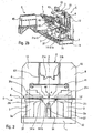
- the invention relates to a splicing device 0 for splicing by laser welding sheet metal strips B after having cut off the ends Bt and Bq.
- the device of the invention as represented in Figures 2a to 3 comprises a main frame 1 fixed to the ground and comprising a platform 11, two uprights 12 parallel to each other and secured by a beam 13 and a lower shearing frame 14 equipped with its two lower blades 141a, 141b.
- the lower shearing frame 14 is adapted to allow the spacing of the two lower blades to be varied to allow clearance adjustment for each pair of lower and upper blades.
- portions of the frame are mounted on rails parallel to the sheet metal scroll axis.
- the two uprights 12 each carry a system of vertical rails 121 which receive an upper shearing frame 2 and its two blades 21a and 21b.
- the upper shearing frame 2 is actuated vertically by shearing cylinders 22 supported by the beam 13.
- the shearing unit C of the device of the invention comprises the upper blades 21a, 21b and lower 141a and 141b and a connecting structure 6 for interconnecting the upper and lower blades, this connecting structure 6 comprising the uprights 12.
- This connecting structure is fixed relative to the frame 1 and extends around the axis A scrolling strip of sheet metal.
- This structure 6 is thus particularly rigid and symmetrical relative to the axis of travel A.
- the upper blades are fixedly mounted on a blade holder so that the spacing between the upper blades remains constant during a cut and in order to balance the forces cutting.
- the upper blade holder is adapted to allow the passage of a laser welding head 4 between the upper blade holder and the lower blades at least when the upper blade holder is spaced from the lower blades as is the case on the figure 3 .
- the welding head 4 has a space enabling it to perform a weld at the very heart of the shearing unit when the lower and upper blades are spaced apart. This characteristic allows a high positioning and welding accuracy as well as a time saving in the sequence between the shearing and welding operations.
- the device of the invention is provided so that the blades are always parallel to each other. This parallelism ensures that the edges of sheared strips are themselves parallel.
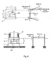
- a device using, for example, precision screw jacks ensures the displacement of the upper blades or preferably of the lower blades in the direction of an increase or decrease. a reduction in the shearing clearance between blades in function of the product data, that is to say of data specific to the sheets to be cut (steel grade, thickness, etc.).
- This data is derived from primary input data denoted PDI for "Primary Data Input" implanted in the automation of the line comprising the device of the invention.
- An electronic game control system can be used to control the precision screw jacks to vary the shear clearance as needed.
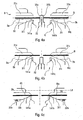
- clamping jaws 3 On the main frame 1 are fixed sets of clamping jaws 3 comprising a first clamping jaw 3a and a second clamping jaw 3b.
- Each of the jaws 3a, 3b grips and moves one end of a band B to weld thus maintaining each of the bands to be welded in a dedicated jaw 3a, 3b.
- These jaws are arranged on either side of the space in which the blades and the welding head 4 can slide.
- the frame 1 also supports a system of horizontal slides 41 perpendicular to the running direction of the band B. These slides continue laterally outside the frame 1. This extension is supported by a structure 42.
- the slide system 41 supports the gooseneck support 43 of the welding head 44, said support 43 moves on the slides 41 from its storage position under the structure 42 to enter completely under the uprights 12 of the main frame 1 to perform the welding of the two ends of strips B held by the sets of clamping jaws 3.
- the upper and lower blades 141a and 141a are separated to allow the sliding of the welding head 44 which performs the welding.
- the laser welding beam is generated by a generator 4.5 (visible on the figures 2a and 2b) fixed at the end of the structure 42 parallel or perpendicular to it. Said laser beam is led to the welding head 44 by an optical path 46 consisting of mirrors.
- the frame 1 also supports a system 5 for the recovery and evacuation of sheared strip falls, this system is particularly visible on the Figures 2a and 4d .
- the splicing device 0 of the invention may be equipped with devices for preheating the edges to be welded as well as devices for post-heating or heat treatment of the weld.
- the band tail Bq and the head of the next band Bt are in the splicing unit in order to be spliced.
- the retractable stop 32 is first placed in the high position and the centering and guiding device B of the line of transformation upstream and downstream of the welding unit position the band tail Bq and the head of the other band Bt bearing respectively on the faces 32b and 32a of the abutment 32.
- the jaws 31s and 31i of the jaws 3a and 3b and the upper shearing frame 2 remain in their original position, that is to say -deside spaced strips of metal.
- the gooseneck frame 43 of the welding unit 4 is always in the storage position.
- the jaws 31s and 31i of the jaws 3a and 3b tighten the two ends of the band Bq and Bt. From this moment the jaws remain tight on the ends of the band in order to immobilize them in the jaws and this until the welding operation is completed (the welding operation appears on the Figures 5a and 5b ).
- the retractable stop 32 descends down and away from the sheets.
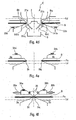
- the jaws 3a and 3b descend into the shearing position at the fixed blades 141a and 141b until they contact the lower jaws 31i with the stops 33a and 33b.
- all or part of these stops can be adjustable in height so as to facilitate the original setting of the machine.
- the upper shearing frame 2 is pushed down by the shearing cylinders 22 the upper blades 21a and 21b in cooperation with the lower blades 141a and 141c shear the ends of the bands Bq and Bt.
- the shearing falls Bcq and Bct are collected by the evacuation system 5.
- the clamping jaws 3a and 3b vertically transport the ends of strips Bq and Bt to contact with upper stops 34a and 34b at the welding plane Ps.
- all or part of these stops can be adjustable in height so as to facilitate the original setting of the machine.
- the clamping jaws 3a and 3b horizontally convey the ends of strips Bq and Bt while remaining at the welding plane Ps.
- a slave displacement system 36a and 36b ensures the relative positioning of the band ends Bq and Bt in the position required for Laser welding taking into account certain parameters from the so-called PDI data such as the thickness of the strips and the desired thickness or under thickness.
- EP 1 591 190 A method for managing the excess thickness of the laser welds applicable with the device of the present invention is described in the patent document.
- EP 1 591 190 It takes into account the inaccuracies of shearing and horizontal displacement of the jaws 3a and 3b.
- only one of the two jaws 3a or 3b is positioned horizontally thanks to the slave displacement system 36a, 36b, the other jaw then comes into contact with lateral stops 35.
- all or part of these stops can be adjustable to facilitate the adjustment of the machine.
- the presence and the combined use of the sets of abutments 33, 34, possibly 35 and the retractable abutment 32 as well as the implementation of the method of automatic adjustment of the clearance between the edges to be welded thanks to the device 36a, 36b allow a positioning Precise, fast and repetitive heads and tails of belts.
- the positioning quality of the edges to be welded is perfectly adapted to the needs of a Laser welding and the times related to the welding are considerably reduced, thus reducing the costs of tape accumulation.
- the gooseneck frame 43 carrying the welding head 44 and guided by the slides 41 moves it above the ends to be welded Bq and Bt under the action of its displacement device 47.
- the laser beam is initiated at the edge of the ends of strips and is maintained over the entire width of the strips to be welded.
- two rollers 49 located immediately behind the welding head and in the axis of the welded joint can forge a possible extra thickness of said seal.
Landscapes
- Engineering & Computer Science (AREA)
- Physics & Mathematics (AREA)
- Optics & Photonics (AREA)
- Mechanical Engineering (AREA)
- Plasma & Fusion (AREA)
- Laser Beam Processing (AREA)
- Shearing Machines (AREA)
Applications Claiming Priority (2)
| Application Number | Priority Date | Filing Date | Title |
|---|---|---|---|
| FR0608349A FR2906171B1 (fr) | 2006-09-22 | 2006-09-22 | Dispositif de raboutage par soudure de bandes de toles |
| PCT/FR2007/001355 WO2008037861A1 (fr) | 2006-09-22 | 2007-08-08 | Dispositif de raboutage par soudure de bandes de tôles |
Publications (2)
| Publication Number | Publication Date |
|---|---|
| EP2064023A1 EP2064023A1 (fr) | 2009-06-03 |
| EP2064023B1 true EP2064023B1 (fr) | 2014-03-19 |
Family
ID=37951733
Family Applications (1)
| Application Number | Title | Priority Date | Filing Date |
|---|---|---|---|
| EP07823407.7A Not-in-force EP2064023B1 (fr) | 2006-09-22 | 2007-08-08 | Dispositif et procédé de raboutage par soudure de bandes de tôles |
Country Status (8)
| Country | Link |
|---|---|
| US (1) | US8445811B2 (enExample) |
| EP (1) | EP2064023B1 (enExample) |
| JP (1) | JP5284263B2 (enExample) |
| KR (1) | KR101063085B1 (enExample) |
| CN (1) | CN101557902B (enExample) |
| FR (1) | FR2906171B1 (enExample) |
| RU (1) | RU2436662C2 (enExample) |
| WO (1) | WO2008037861A1 (enExample) |
Families Citing this family (31)
| Publication number | Priority date | Publication date | Assignee | Title |
|---|---|---|---|---|
| RS52076B (sr) * | 2006-04-27 | 2012-06-30 | Sms Siemag Aktiengesellschaft | Uređaj za spajanje traka i postupak za rad uređaja |
| DE102007052801B4 (de) * | 2007-11-06 | 2010-10-07 | Bruker Daltonik Gmbh | Ionenmobilitätsspektrometer mit Substanzsammler |
| DE102008063277A1 (de) * | 2008-12-29 | 2010-07-08 | Bwg Bergwerk- Und Walzwerk-Maschinenbau Gmbh | Verfahren und Vorrichtung zum Verbinden von Metallbändern |
| CA2796369A1 (en) * | 2010-04-13 | 2011-10-20 | National Research Council Of Canada | Laser processing control method |
| JP5843847B2 (ja) * | 2010-04-23 | 2016-01-13 | シーメンス ヴェ メタルス テクノロジーズ エスアーエスSiemens VAI Metals Technologies SAS | 接合溶接部の誘導熱処理に適した、鋼ストリップの端部を接合する方法 |
| JP5975725B2 (ja) * | 2012-05-14 | 2016-08-23 | 多田電機株式会社 | レーザビーム溶接装置及びレーザビーム溶接装置における金属板の切断方法 |
| JP6303800B2 (ja) * | 2013-05-27 | 2018-04-04 | 新日鐵住金株式会社 | 鋼板溶接装置、鋼板の切断方法および鋼板の溶接方法 |
| EP2821176A1 (fr) | 2013-07-02 | 2015-01-07 | Siemens VAI Metals Technologies GmbH | Dispositif de déplacement d'un arrangement de découpe et de soudage de bandes métalliques ; Méthode de découpe et de soudage utilisant un tel dispositif |
| CN103752938A (zh) * | 2013-12-13 | 2014-04-30 | 宋芬 | 切片机 |
| US20150165555A1 (en) * | 2013-12-13 | 2015-06-18 | Global Automotive Systems, Llc | Tube seam weld station and weld shoes |
| WO2015162445A1 (fr) | 2014-04-25 | 2015-10-29 | Arcelormittal Investigación Y Desarrollo Sl | Procede et dispositif de preparation de toles d'acier aluminiees destinees a etre soudees puis durcies sous presse; flan soude correspondant |
| DE102015204852A1 (de) | 2014-06-13 | 2015-12-17 | Sms Group Gmbh | Vorrichtung zum Verbinden von Bandenden von Stahlbändern |
| TWI571347B (zh) * | 2014-12-11 | 2017-02-21 | 財團法人金屬工業研究發展中心 | 金屬板帶之製造方法 |
| TWI625188B (zh) * | 2016-05-09 | 2018-06-01 | 中國鋼鐵股份有限公司 | 開凹機及其控制方法 |
| CN106271043B (zh) * | 2016-09-08 | 2018-09-07 | 珠海格力电器股份有限公司 | 一种激光焊接系统及方法 |
| CN106563844B (zh) * | 2016-11-03 | 2019-09-06 | 江苏中天科技股份有限公司 | 一种光缆纵包钢带或铝带自动焊接装置用带头定位夹持装置 |
| CN107052160B (zh) * | 2017-04-21 | 2019-04-02 | 合肥梦飞电器有限公司 | 切割机 |
| CN107052429B (zh) * | 2017-04-21 | 2019-06-18 | 合肥梦飞电器有限公司 | 切割机 |
| JP6994324B2 (ja) * | 2017-08-31 | 2022-01-14 | 株式会社神戸製鋼所 | 接合体の製造方法および製造装置 |
| CN108067718B (zh) * | 2018-02-11 | 2023-12-26 | 苏州聚生精密冲件有限公司 | 热保护器的双金属片银点自动化焊接设备 |
| CN109909615A (zh) * | 2019-03-28 | 2019-06-21 | 武汉钢铁有限公司 | 板形不良钢带的激光穿带焊接装备及其焊接方法 |
| ES3056353T3 (en) * | 2019-11-05 | 2026-02-19 | Magna Int Inc | Fixture assembly for supporting blanks during shearing and welding operations |
| CN111390279B (zh) * | 2020-04-23 | 2024-06-21 | 马鞍山市晨旭机械制造有限公司 | 一种环件切割用带锯条焊接修复工位台及焊接修复方法 |
| CN111496341B (zh) * | 2020-04-29 | 2022-04-08 | 中天集团上海超导技术有限公司 | 一种超导带材自动焊接机 |
| WO2022011374A2 (en) | 2020-07-06 | 2022-01-13 | Novelis Inc. | Metal joiner system, associated methods, and products |
| RU205266U1 (ru) * | 2020-12-30 | 2021-07-06 | Общество с ограниченной ответственностью "НПК Морсвязьавтоматика" | Стол для установки обрабатываемых деталей |
| CN112809063A (zh) * | 2021-02-04 | 2021-05-18 | 极能电气(苏州)有限公司 | 一种铜带编织机的裁切设备 |
| JP7534240B2 (ja) * | 2021-03-05 | 2024-08-14 | 本田技研工業株式会社 | 接合装置 |
| CN113146271B (zh) * | 2021-04-09 | 2022-06-14 | 燕山大学 | 可调式剪切对焊装置及其剪切对焊方法 |
| CN113399817B (zh) * | 2021-07-14 | 2022-07-08 | 深圳市贝尔激光技术有限公司 | 一种激光设备 |
| CN113910473A (zh) * | 2021-10-19 | 2022-01-11 | 麦卡电工器材(陆河)有限公司 | 一种云母板激光定位剪板工艺 |
Family Cites Families (25)
| Publication number | Priority date | Publication date | Assignee | Title |
|---|---|---|---|---|
| GB1422950A (en) * | 1972-05-31 | 1976-01-28 | Harris R E | Apparatus for shearing sheet material |
| JPS59135886U (ja) * | 1983-02-28 | 1984-09-11 | 川崎製鉄株式会社 | レ−ザ−溶接機 |
| DE3473422D1 (en) * | 1984-02-27 | 1988-09-22 | Kawasaki Steel Co | An apparatus for butt welding steel strips by using a laser beam in a steel strip-processing line |
| JPS62187584A (ja) * | 1986-02-12 | 1987-08-15 | Mitsubishi Electric Corp | ストリツプ接続装置 |
| EP0258454B1 (en) * | 1986-02-28 | 1993-04-21 | Kawasaki Steel Corporation | Method and device for cutting and welding steel belts |
| JPH0122475Y2 (enExample) | 1986-05-19 | 1989-07-04 | ||
| SU1630160A1 (ru) * | 1988-11-15 | 1992-06-23 | Головное конструкторское бюро "Станкосистема" | Устройство дл транспортировки лазерного луча |
| DE3909925A1 (de) * | 1989-03-25 | 1990-09-27 | Oxytechnik Ges Systemtech | Bandschweissanlage |
| US5045668A (en) * | 1990-04-12 | 1991-09-03 | Armco Inc. | Apparatus and method for automatically aligning a welding device for butt welding workpieces |
| ATE100009T1 (de) * | 1990-10-20 | 1994-01-15 | Bwg Bergwerk Walzwerk | Bandschweissmaschine. |
| US5229571A (en) * | 1991-07-08 | 1993-07-20 | Armco Steel Co., L.P. | High production laser welding assembly and method |
| RU2150362C1 (ru) * | 1992-04-12 | 2000-06-10 | Эльпатроник АГ | Способ и устройство для сварки листов в сварную листовую заготовку посредством лазера |
| DE59302322D1 (de) | 1992-04-12 | 1996-05-30 | Elpatronic Ag | Verfahren und Vorrichtung zum Schweissen von Blechen zu Platinen mittels Laser |
| FR2704471B1 (fr) * | 1993-04-28 | 1995-07-21 | Lorraine Laminage | Installation de positionnement bord à bord et de soudage au moyen d'un faisceau laser d'au moins deux flans de tôle. |
| FR2715092B1 (fr) * | 1994-01-20 | 1996-04-05 | Lorraine Laminage | Dispositif de mise en référence bord à bord d'au moins deux flans de tôle dans une installation de soudage au moyen d'un faisceau à haute densité d'énergie. |
| RU2095431C1 (ru) * | 1996-03-15 | 1997-11-10 | Акционерное общество закрытого типа "Технолазер" | Установка для лазерной обработки листовых материалов |
| US5901627A (en) * | 1996-08-13 | 1999-05-11 | Littell International, Inc. | Apparatus and method for shearing material |
| JPH1158122A (ja) * | 1997-08-12 | 1999-03-02 | Amada Washino Co Ltd | 剪断加工機 |
| FR2778350B1 (fr) * | 1998-05-05 | 2000-07-28 | Kvaerner Metals Clecim | Installation d'accumulation d'un produit en bande |
| JP2000246469A (ja) * | 1999-02-26 | 2000-09-12 | Dainippon Screen Mfg Co Ltd | 帯状金属薄板の接続装置および接続方法 |
| US6204469B1 (en) * | 1999-03-04 | 2001-03-20 | Honda Giken Kogyo Kabushiki Kaisha | Laser welding system |
| JP3399445B2 (ja) * | 2000-05-25 | 2003-04-21 | 三菱電機株式会社 | 鋼板連続処理ラインにおけるストリップ接続方法 |
| US6803538B2 (en) * | 2001-08-31 | 2004-10-12 | Honda Canada Inc. | Laser welding system |
| CN1152764C (zh) * | 2002-01-30 | 2004-06-09 | 华中科技大学 | 薄板激光切割—焊接组合工艺及其设备 |
| CN2579592Y (zh) * | 2002-11-06 | 2003-10-15 | 大连三高应用技术发展公司 | 一种新型剪切对焊机 |
-
2006
- 2006-09-22 FR FR0608349A patent/FR2906171B1/fr not_active Expired - Fee Related
-
2007
- 2007-08-08 WO PCT/FR2007/001355 patent/WO2008037861A1/fr not_active Ceased
- 2007-08-08 JP JP2009528746A patent/JP5284263B2/ja not_active Expired - Fee Related
- 2007-08-08 KR KR1020097005755A patent/KR101063085B1/ko not_active Expired - Fee Related
- 2007-08-08 CN CN2007800345096A patent/CN101557902B/zh not_active Expired - Fee Related
- 2007-08-08 RU RU2009115191/02A patent/RU2436662C2/ru not_active IP Right Cessation
- 2007-08-08 EP EP07823407.7A patent/EP2064023B1/fr not_active Not-in-force
- 2007-08-08 US US12/441,753 patent/US8445811B2/en not_active Expired - Fee Related
Also Published As
| Publication number | Publication date |
|---|---|
| KR101063085B1 (ko) | 2011-09-07 |
| JP5284263B2 (ja) | 2013-09-11 |
| WO2008037861A1 (fr) | 2008-04-03 |
| US8445811B2 (en) | 2013-05-21 |
| FR2906171B1 (fr) | 2009-05-15 |
| RU2009115191A (ru) | 2010-10-27 |
| CN101557902A (zh) | 2009-10-14 |
| US20090294418A1 (en) | 2009-12-03 |
| EP2064023A1 (fr) | 2009-06-03 |
| CN101557902B (zh) | 2012-11-07 |
| JP2010503541A (ja) | 2010-02-04 |
| FR2906171A1 (fr) | 2008-03-28 |
| KR20090073110A (ko) | 2009-07-02 |
| RU2436662C2 (ru) | 2011-12-20 |
Similar Documents
| Publication | Publication Date | Title |
|---|---|---|
| EP2064023B1 (fr) | Dispositif et procédé de raboutage par soudure de bandes de tôles | |
| JP2010503541A5 (enExample) | ||
| JP5438163B2 (ja) | 造管設備に適用される鉄板ストリップ接合装置 | |
| EP0151848B2 (en) | An apparatus for butt welding steel strips by using a laser beam in a steel strip-processing line | |
| US4623777A (en) | Apparatus for butt welding steel strips by using a laser beam in a steel strip-processing line | |
| CZ290110B6 (cs) | Způsob a zařízení na přípravu okrajů pro svařování plechů na tupo laserem pro vytváření sloľených plechů | |
| FR2704471A1 (fr) | Installation de positionnement bord à bord et de soudage au moyen d'un faisceau laser d'au moins deux flans de tôle. | |
| CH444631A (fr) | Procédé pour joindre les extrémités de deux feuillards et installation pour sa mise en oeuvre | |
| EP0659518A1 (fr) | Installation de raboutage et de soudage au moyen d'un faisceau laser de deux bobines de bandes métalliques pour former une bande métallique continue | |
| EP1591190B1 (fr) | Procédé de soudure de deux tôles métalliques | |
| EP1127654B1 (fr) | Machine à rabouter des bandes métalliques et son procédé de mise en oeuvre | |
| EP3530404A1 (fr) | Dispositif et procédé d'usinage d'une extrémité d'un panneau élémentaire en vue de son soudage par friction malaxage | |
| EP0245145A1 (fr) | Procédé de soudage au laser et installation mettant en oeuvre ce procédé | |
| EP0650796B1 (fr) | Procédé et dispositif d'équerrage et soudage de bandes métalliques | |
| EP3529187B1 (fr) | Dispositif et procédé de déviation et d'échantillonnage pour élément en plaque | |
| FR2597512A1 (fr) | Procede et dispositif pour la mise en place de collets en tole d'aluminium ou analogue sur les raccords de tiges a anode faisant saillie de blocs d'anode | |
| FR2526699A1 (fr) | Appareil et procede pour realiser la commande programmee de fonctions de travail, notamment pour le soudage d'elements de batterie | |
| EP0977649B1 (fr) | Procede de mise en place de deux flans de tole pour etre soudes bord a bord par un faisceau a haute densite d'energie | |
| JP3397922B2 (ja) | 移動鋼板の接合方法および装置 | |
| EP0604247B1 (fr) | Procédé de soudage bord à bord d'au moins deux tÔles | |
| EP0781621B1 (fr) | Procédé d'épissure de bandes métalliques et machine pour sa mise en oeuvre | |
| US7757458B2 (en) | Packaging machine equipped with independent cutting and welding bars | |
| JP7849232B2 (ja) | 突き合せ装置および突き合せ方法 | |
| JP2005297056A (ja) | ワーク切り離し装置 | |
| EP3038963B1 (fr) | Procede de raboutage de deux articles thermofusibles sous forme de bandes ou de nappes, et module de raboutage pour la mise en oeuvre dudit procede |
Legal Events
| Date | Code | Title | Description |
|---|---|---|---|
| PUAI | Public reference made under article 153(3) epc to a published international application that has entered the european phase |
Free format text: ORIGINAL CODE: 0009012 |
|
| 17P | Request for examination filed |
Effective date: 20090123 |
|
| AK | Designated contracting states |
Kind code of ref document: A1 Designated state(s): AT BE BG CH CY CZ DE DK EE ES FI FR GB GR HU IE IS IT LI LT LU LV MC MT NL PL PT RO SE SI SK TR |
|
| AX | Request for extension of the european patent |
Extension state: AL BA HR MK RS |
|
| RIN1 | Information on inventor provided before grant (corrected) |
Inventor name: PERRET, JEAN Inventor name: THOMASSON, HERVE Inventor name: BARJON, STEPHANE |
|
| 17Q | First examination report despatched |
Effective date: 20090721 |
|
| RBV | Designated contracting states (corrected) |
Designated state(s): AT BE DE FR GB IT |
|
| DAX | Request for extension of the european patent (deleted) | ||
| GRAP | Despatch of communication of intention to grant a patent |
Free format text: ORIGINAL CODE: EPIDOSNIGR1 |
|
| INTG | Intention to grant announced |
Effective date: 20130718 |
|
| RIN1 | Information on inventor provided before grant (corrected) |
Inventor name: THOMASSON, HERVE Inventor name: PERRET, JEAN Inventor name: BARJON, STEPHANE |
|
| GRAP | Despatch of communication of intention to grant a patent |
Free format text: ORIGINAL CODE: EPIDOSNIGR1 |
|
| INTG | Intention to grant announced |
Effective date: 20131008 |
|
| GRAS | Grant fee paid |
Free format text: ORIGINAL CODE: EPIDOSNIGR3 |
|
| GRAA | (expected) grant |
Free format text: ORIGINAL CODE: 0009210 |
|
| AK | Designated contracting states |
Kind code of ref document: B1 Designated state(s): AT BE DE FR GB IT |
|
| REG | Reference to a national code |
Ref country code: GB Ref legal event code: FG4D Free format text: NOT ENGLISH |
|
| REG | Reference to a national code |
Ref country code: AT Ref legal event code: REF Ref document number: 657309 Country of ref document: AT Kind code of ref document: T Effective date: 20140415 |
|
| REG | Reference to a national code |
Ref country code: DE Ref legal event code: R096 Ref document number: 602007035684 Country of ref document: DE Effective date: 20140430 |
|
| REG | Reference to a national code |
Ref country code: DE Ref legal event code: R097 Ref document number: 602007035684 Country of ref document: DE |
|
| PLBE | No opposition filed within time limit |
Free format text: ORIGINAL CODE: 0009261 |
|
| STAA | Information on the status of an ep patent application or granted ep patent |
Free format text: STATUS: NO OPPOSITION FILED WITHIN TIME LIMIT |
|
| 26N | No opposition filed |
Effective date: 20141222 |
|
| REG | Reference to a national code |
Ref country code: DE Ref legal event code: R097 Ref document number: 602007035684 Country of ref document: DE Effective date: 20141222 |
|
| REG | Reference to a national code |
Ref country code: FR Ref legal event code: PLFP Year of fee payment: 9 |
|
| REG | Reference to a national code |
Ref country code: DE Ref legal event code: R082 Ref document number: 602007035684 Country of ref document: DE Representative=s name: FISCHER, MICHAEL, DR., DE Ref country code: DE Ref legal event code: R081 Ref document number: 602007035684 Country of ref document: DE Owner name: PRIMETALS TECHNOLOGIES FRANCE SAS, FR Free format text: FORMER OWNER: SIEMENS VAI METALS TECHNOLOGIES SAS, SAINT CHAMOND, FR Ref country code: DE Ref legal event code: R082 Ref document number: 602007035684 Country of ref document: DE Representative=s name: KINNSTAETTER, KLAUS, DIPL.-PHYS.UNIV., DE |
|
| REG | Reference to a national code |
Ref country code: FR Ref legal event code: CA Effective date: 20160204 Ref country code: FR Ref legal event code: CD Owner name: PRIMETALS TECHNOLOGIES FRANCE SAS, FR Effective date: 20160204 |
|
| REG | Reference to a national code |
Ref country code: DE Ref legal event code: R082 Ref document number: 602007035684 Country of ref document: DE Representative=s name: KINNSTAETTER, KLAUS, DIPL.-PHYS.UNIV., DE |
|
| REG | Reference to a national code |
Ref country code: FR Ref legal event code: PLFP Year of fee payment: 10 |
|
| PGFP | Annual fee paid to national office [announced via postgrant information from national office to epo] |
Ref country code: DE Payment date: 20160822 Year of fee payment: 10 Ref country code: GB Payment date: 20160819 Year of fee payment: 10 Ref country code: IT Payment date: 20160825 Year of fee payment: 10 |
|
| PGFP | Annual fee paid to national office [announced via postgrant information from national office to epo] |
Ref country code: AT Payment date: 20160822 Year of fee payment: 10 Ref country code: FR Payment date: 20160822 Year of fee payment: 10 |
|
| PGFP | Annual fee paid to national office [announced via postgrant information from national office to epo] |
Ref country code: BE Payment date: 20160819 Year of fee payment: 10 |
|
| REG | Reference to a national code |
Ref country code: AT Ref legal event code: PC Ref document number: 657309 Country of ref document: AT Kind code of ref document: T Owner name: PRIMETALS TECHNOLOGIES FRANCE SAS, FR Effective date: 20170403 |
|
| REG | Reference to a national code |
Ref country code: DE Ref legal event code: R119 Ref document number: 602007035684 Country of ref document: DE |
|
| REG | Reference to a national code |
Ref country code: AT Ref legal event code: MM01 Ref document number: 657309 Country of ref document: AT Kind code of ref document: T Effective date: 20170808 |
|
| GBPC | Gb: european patent ceased through non-payment of renewal fee |
Effective date: 20170808 |
|
| REG | Reference to a national code |
Ref country code: FR Ref legal event code: ST Effective date: 20180430 |
|
| PG25 | Lapsed in a contracting state [announced via postgrant information from national office to epo] |
Ref country code: AT Free format text: LAPSE BECAUSE OF NON-PAYMENT OF DUE FEES Effective date: 20170808 |
|
| REG | Reference to a national code |
Ref country code: BE Ref legal event code: HC Owner name: PRIMETALS TECHNOLOGIES FRANCE SAS; FR Free format text: DETAILS ASSIGNMENT: CHANGE OF OWNER(S), CHANGEMENT NOM PROPRIETAIRE, NOM ET ADRESSE; FORMER OWNER NAME: SIEMENS VAI METALS TECHNOLOGIES SAS Effective date: 20160307 Ref country code: BE Ref legal event code: MM Effective date: 20170831 |
|
| PG25 | Lapsed in a contracting state [announced via postgrant information from national office to epo] |
Ref country code: DE Free format text: LAPSE BECAUSE OF NON-PAYMENT OF DUE FEES Effective date: 20180301 Ref country code: GB Free format text: LAPSE BECAUSE OF NON-PAYMENT OF DUE FEES Effective date: 20170808 |
|
| PG25 | Lapsed in a contracting state [announced via postgrant information from national office to epo] |
Ref country code: BE Free format text: LAPSE BECAUSE OF NON-PAYMENT OF DUE FEES Effective date: 20170831 Ref country code: FR Free format text: LAPSE BECAUSE OF NON-PAYMENT OF DUE FEES Effective date: 20170831 Ref country code: IT Free format text: LAPSE BECAUSE OF NON-PAYMENT OF DUE FEES Effective date: 20170808 |