EP2063152A1 - Procédé de commutation d'un engrenage d'embrayage double - Google Patents
Procédé de commutation d'un engrenage d'embrayage double Download PDFInfo
- Publication number
- EP2063152A1 EP2063152A1 EP08105379A EP08105379A EP2063152A1 EP 2063152 A1 EP2063152 A1 EP 2063152A1 EP 08105379 A EP08105379 A EP 08105379A EP 08105379 A EP08105379 A EP 08105379A EP 2063152 A1 EP2063152 A1 EP 2063152A1
- Authority
- EP
- European Patent Office
- Prior art keywords
- clutch
- engine
- torque
- engine speed
- characteristic
- Prior art date
- Legal status (The legal status is an assumption and is not a legal conclusion. Google has not performed a legal analysis and makes no representation as to the accuracy of the status listed.)
- Granted
Links
- 238000000034 method Methods 0.000 title claims abstract description 22
- 230000008878 coupling Effects 0.000 title abstract description 5
- 238000010168 coupling process Methods 0.000 title abstract description 5
- 238000005859 coupling reaction Methods 0.000 title abstract description 5
- 230000005540 biological transmission Effects 0.000 claims description 50
- 230000015556 catabolic process Effects 0.000 claims description 12
- 238000006731 degradation reaction Methods 0.000 claims description 11
- 230000001419 dependent effect Effects 0.000 claims description 10
- 230000006978 adaptation Effects 0.000 claims description 7
- 238000010276 construction Methods 0.000 claims description 7
- 238000005562 fading Methods 0.000 description 2
- 230000001133 acceleration Effects 0.000 description 1
- 230000001276 controlling effect Effects 0.000 description 1
- 230000000593 degrading effect Effects 0.000 description 1
- 230000001934 delay Effects 0.000 description 1
- 230000009977 dual effect Effects 0.000 description 1
- 230000001105 regulatory effect Effects 0.000 description 1
- 230000036962 time dependent Effects 0.000 description 1
Images


Classifications
-
- F—MECHANICAL ENGINEERING; LIGHTING; HEATING; WEAPONS; BLASTING
- F16—ENGINEERING ELEMENTS AND UNITS; GENERAL MEASURES FOR PRODUCING AND MAINTAINING EFFECTIVE FUNCTIONING OF MACHINES OR INSTALLATIONS; THERMAL INSULATION IN GENERAL
- F16D—COUPLINGS FOR TRANSMITTING ROTATION; CLUTCHES; BRAKES
- F16D48/00—External control of clutches
- F16D48/06—Control by electric or electronic means, e.g. of fluid pressure
- F16D48/08—Regulating clutch take-up on starting
-
- F—MECHANICAL ENGINEERING; LIGHTING; HEATING; WEAPONS; BLASTING
- F16—ENGINEERING ELEMENTS AND UNITS; GENERAL MEASURES FOR PRODUCING AND MAINTAINING EFFECTIVE FUNCTIONING OF MACHINES OR INSTALLATIONS; THERMAL INSULATION IN GENERAL
- F16H—GEARING
- F16H61/00—Control functions within control units of change-speed- or reversing-gearings for conveying rotary motion ; Control of exclusively fluid gearing, friction gearing, gearings with endless flexible members or other particular types of gearing
- F16H61/68—Control functions within control units of change-speed- or reversing-gearings for conveying rotary motion ; Control of exclusively fluid gearing, friction gearing, gearings with endless flexible members or other particular types of gearing specially adapted for stepped gearings
- F16H61/684—Control functions within control units of change-speed- or reversing-gearings for conveying rotary motion ; Control of exclusively fluid gearing, friction gearing, gearings with endless flexible members or other particular types of gearing specially adapted for stepped gearings without interruption of drive
- F16H61/688—Control functions within control units of change-speed- or reversing-gearings for conveying rotary motion ; Control of exclusively fluid gearing, friction gearing, gearings with endless flexible members or other particular types of gearing specially adapted for stepped gearings without interruption of drive with two inputs, e.g. selection of one of two torque-flow paths by clutches
-
- F—MECHANICAL ENGINEERING; LIGHTING; HEATING; WEAPONS; BLASTING
- F16—ENGINEERING ELEMENTS AND UNITS; GENERAL MEASURES FOR PRODUCING AND MAINTAINING EFFECTIVE FUNCTIONING OF MACHINES OR INSTALLATIONS; THERMAL INSULATION IN GENERAL
- F16D—COUPLINGS FOR TRANSMITTING ROTATION; CLUTCHES; BRAKES
- F16D2500/00—External control of clutches by electric or electronic means
- F16D2500/10—System to be controlled
- F16D2500/108—Gear
- F16D2500/1086—Concentric shafts
-
- F—MECHANICAL ENGINEERING; LIGHTING; HEATING; WEAPONS; BLASTING
- F16—ENGINEERING ELEMENTS AND UNITS; GENERAL MEASURES FOR PRODUCING AND MAINTAINING EFFECTIVE FUNCTIONING OF MACHINES OR INSTALLATIONS; THERMAL INSULATION IN GENERAL
- F16D—COUPLINGS FOR TRANSMITTING ROTATION; CLUTCHES; BRAKES
- F16D2500/00—External control of clutches by electric or electronic means
- F16D2500/30—Signal inputs
- F16D2500/304—Signal inputs from the clutch
- F16D2500/3042—Signal inputs from the clutch from the output shaft
- F16D2500/30426—Speed of the output shaft
-
- F—MECHANICAL ENGINEERING; LIGHTING; HEATING; WEAPONS; BLASTING
- F16—ENGINEERING ELEMENTS AND UNITS; GENERAL MEASURES FOR PRODUCING AND MAINTAINING EFFECTIVE FUNCTIONING OF MACHINES OR INSTALLATIONS; THERMAL INSULATION IN GENERAL
- F16D—COUPLINGS FOR TRANSMITTING ROTATION; CLUTCHES; BRAKES
- F16D2500/00—External control of clutches by electric or electronic means
- F16D2500/30—Signal inputs
- F16D2500/306—Signal inputs from the engine
- F16D2500/3067—Speed of the engine
-
- F—MECHANICAL ENGINEERING; LIGHTING; HEATING; WEAPONS; BLASTING
- F16—ENGINEERING ELEMENTS AND UNITS; GENERAL MEASURES FOR PRODUCING AND MAINTAINING EFFECTIVE FUNCTIONING OF MACHINES OR INSTALLATIONS; THERMAL INSULATION IN GENERAL
- F16D—COUPLINGS FOR TRANSMITTING ROTATION; CLUTCHES; BRAKES
- F16D2500/00—External control of clutches by electric or electronic means
- F16D2500/30—Signal inputs
- F16D2500/308—Signal inputs from the transmission
- F16D2500/3081—Signal inputs from the transmission from the input shaft
- F16D2500/30816—Speed of the input shaft
-
- F—MECHANICAL ENGINEERING; LIGHTING; HEATING; WEAPONS; BLASTING
- F16—ENGINEERING ELEMENTS AND UNITS; GENERAL MEASURES FOR PRODUCING AND MAINTAINING EFFECTIVE FUNCTIONING OF MACHINES OR INSTALLATIONS; THERMAL INSULATION IN GENERAL
- F16D—COUPLINGS FOR TRANSMITTING ROTATION; CLUTCHES; BRAKES
- F16D2500/00—External control of clutches by electric or electronic means
- F16D2500/30—Signal inputs
- F16D2500/314—Signal inputs from the user
- F16D2500/3146—Signal inputs from the user input from levers
- F16D2500/31466—Gear lever
-
- F—MECHANICAL ENGINEERING; LIGHTING; HEATING; WEAPONS; BLASTING
- F16—ENGINEERING ELEMENTS AND UNITS; GENERAL MEASURES FOR PRODUCING AND MAINTAINING EFFECTIVE FUNCTIONING OF MACHINES OR INSTALLATIONS; THERMAL INSULATION IN GENERAL
- F16D—COUPLINGS FOR TRANSMITTING ROTATION; CLUTCHES; BRAKES
- F16D2500/00—External control of clutches by electric or electronic means
- F16D2500/50—Problem to be solved by the control system
- F16D2500/502—Relating the clutch
- F16D2500/50224—Drive-off
-
- F—MECHANICAL ENGINEERING; LIGHTING; HEATING; WEAPONS; BLASTING
- F16—ENGINEERING ELEMENTS AND UNITS; GENERAL MEASURES FOR PRODUCING AND MAINTAINING EFFECTIVE FUNCTIONING OF MACHINES OR INSTALLATIONS; THERMAL INSULATION IN GENERAL
- F16D—COUPLINGS FOR TRANSMITTING ROTATION; CLUTCHES; BRAKES
- F16D2500/00—External control of clutches by electric or electronic means
- F16D2500/50—Problem to be solved by the control system
- F16D2500/502—Relating the clutch
- F16D2500/50227—Control of clutch to control engine
-
- F—MECHANICAL ENGINEERING; LIGHTING; HEATING; WEAPONS; BLASTING
- F16—ENGINEERING ELEMENTS AND UNITS; GENERAL MEASURES FOR PRODUCING AND MAINTAINING EFFECTIVE FUNCTIONING OF MACHINES OR INSTALLATIONS; THERMAL INSULATION IN GENERAL
- F16D—COUPLINGS FOR TRANSMITTING ROTATION; CLUTCHES; BRAKES
- F16D2500/00—External control of clutches by electric or electronic means
- F16D2500/50—Problem to be solved by the control system
- F16D2500/506—Relating the transmission
- F16D2500/50684—Torque resume after shifting
-
- F—MECHANICAL ENGINEERING; LIGHTING; HEATING; WEAPONS; BLASTING
- F16—ENGINEERING ELEMENTS AND UNITS; GENERAL MEASURES FOR PRODUCING AND MAINTAINING EFFECTIVE FUNCTIONING OF MACHINES OR INSTALLATIONS; THERMAL INSULATION IN GENERAL
- F16D—COUPLINGS FOR TRANSMITTING ROTATION; CLUTCHES; BRAKES
- F16D2500/00—External control of clutches by electric or electronic means
- F16D2500/70—Details about the implementation of the control system
- F16D2500/704—Output parameters from the control unit; Target parameters to be controlled
- F16D2500/70422—Clutch parameters
- F16D2500/70438—From the output shaft
- F16D2500/7044—Output shaft torque
-
- F—MECHANICAL ENGINEERING; LIGHTING; HEATING; WEAPONS; BLASTING
- F16—ENGINEERING ELEMENTS AND UNITS; GENERAL MEASURES FOR PRODUCING AND MAINTAINING EFFECTIVE FUNCTIONING OF MACHINES OR INSTALLATIONS; THERMAL INSULATION IN GENERAL
- F16D—COUPLINGS FOR TRANSMITTING ROTATION; CLUTCHES; BRAKES
- F16D2500/00—External control of clutches by electric or electronic means
- F16D2500/70—Details about the implementation of the control system
- F16D2500/704—Output parameters from the control unit; Target parameters to be controlled
- F16D2500/70452—Engine parameters
- F16D2500/70454—Engine speed
-
- F—MECHANICAL ENGINEERING; LIGHTING; HEATING; WEAPONS; BLASTING
- F16—ENGINEERING ELEMENTS AND UNITS; GENERAL MEASURES FOR PRODUCING AND MAINTAINING EFFECTIVE FUNCTIONING OF MACHINES OR INSTALLATIONS; THERMAL INSULATION IN GENERAL
- F16H—GEARING
- F16H59/00—Control inputs to control units of change-speed-, or reversing-gearings for conveying rotary motion
- F16H59/36—Inputs being a function of speed
- F16H2059/366—Engine or motor speed
-
- F—MECHANICAL ENGINEERING; LIGHTING; HEATING; WEAPONS; BLASTING
- F16—ENGINEERING ELEMENTS AND UNITS; GENERAL MEASURES FOR PRODUCING AND MAINTAINING EFFECTIVE FUNCTIONING OF MACHINES OR INSTALLATIONS; THERMAL INSULATION IN GENERAL
- F16H—GEARING
- F16H61/00—Control functions within control units of change-speed- or reversing-gearings for conveying rotary motion ; Control of exclusively fluid gearing, friction gearing, gearings with endless flexible members or other particular types of gearing
- F16H2061/0075—Control functions within control units of change-speed- or reversing-gearings for conveying rotary motion ; Control of exclusively fluid gearing, friction gearing, gearings with endless flexible members or other particular types of gearing characterised by a particular control method
- F16H2061/0096—Control functions within control units of change-speed- or reversing-gearings for conveying rotary motion ; Control of exclusively fluid gearing, friction gearing, gearings with endless flexible members or other particular types of gearing characterised by a particular control method using a parameter map
-
- F—MECHANICAL ENGINEERING; LIGHTING; HEATING; WEAPONS; BLASTING
- F16—ENGINEERING ELEMENTS AND UNITS; GENERAL MEASURES FOR PRODUCING AND MAINTAINING EFFECTIVE FUNCTIONING OF MACHINES OR INSTALLATIONS; THERMAL INSULATION IN GENERAL
- F16H—GEARING
- F16H2302/00—Determining the way or trajectory to new ratio, e.g. by determining speed, torque or time parameters for shift transition
-
- F—MECHANICAL ENGINEERING; LIGHTING; HEATING; WEAPONS; BLASTING
- F16—ENGINEERING ELEMENTS AND UNITS; GENERAL MEASURES FOR PRODUCING AND MAINTAINING EFFECTIVE FUNCTIONING OF MACHINES OR INSTALLATIONS; THERMAL INSULATION IN GENERAL
- F16H—GEARING
- F16H2306/00—Shifting
- F16H2306/40—Shifting activities
- F16H2306/44—Removing torque from current gears
-
- F—MECHANICAL ENGINEERING; LIGHTING; HEATING; WEAPONS; BLASTING
- F16—ENGINEERING ELEMENTS AND UNITS; GENERAL MEASURES FOR PRODUCING AND MAINTAINING EFFECTIVE FUNCTIONING OF MACHINES OR INSTALLATIONS; THERMAL INSULATION IN GENERAL
- F16H—GEARING
- F16H2306/00—Shifting
- F16H2306/40—Shifting activities
- F16H2306/52—Applying torque to new gears
-
- F—MECHANICAL ENGINEERING; LIGHTING; HEATING; WEAPONS; BLASTING
- F16—ENGINEERING ELEMENTS AND UNITS; GENERAL MEASURES FOR PRODUCING AND MAINTAINING EFFECTIVE FUNCTIONING OF MACHINES OR INSTALLATIONS; THERMAL INSULATION IN GENERAL
- F16H—GEARING
- F16H2306/00—Shifting
- F16H2306/40—Shifting activities
- F16H2306/54—Synchronizing engine speed to transmission input speed
-
- F—MECHANICAL ENGINEERING; LIGHTING; HEATING; WEAPONS; BLASTING
- F16—ENGINEERING ELEMENTS AND UNITS; GENERAL MEASURES FOR PRODUCING AND MAINTAINING EFFECTIVE FUNCTIONING OF MACHINES OR INSTALLATIONS; THERMAL INSULATION IN GENERAL
- F16H—GEARING
- F16H2312/00—Driving activities
- F16H2312/02—Driving off
Definitions
- the invention relates to a method for switching a dual-clutch transmission in a motor-driven vehicle, with a first clutch and a second clutch and with a first partial transmission and a second partial transmission, wherein the first partial transmission, the first clutch and a first group of gears and the second sub-transmission, the second clutch and a second group of gears are assigned.
- the gearshift or gearshift is normally performed in one of two ways:
- a target gear is first engaged in the second sub-transmission, which is not intended to transmit torque before shifting.
- the applied engine torque is transmitted from the first clutch to the second clutch according to a predetermined engine load.
- the second passive clutch is controlled under slip so that the engine speed corresponds to the speed of an input shaft of the first sub-transmission.
- the engine speed is controlled by reducing the engine torque and controlling the torque capacity of the second clutch to the speed of an input shaft of the second sub-transmission.
- the second clutch can be completely closed.
- Such a regulation of the torque capacities of the first and second clutches and the subsequent adaptation of the engine speed to the rotational speed of the second input shaft of the second subtransmission is in the EP 1 507 103 B1 disclosed.
- the invention is therefore based on the object already to provide a new improved method for switching the dual-clutch transmission during startup of the vehicle.
- the inventive method is characterized in that the adjustment of the engine speed via the structure of the torque capacity of the second clutch, wherein the torque capacity of the second clutch is guided to a torque end, in which a target gear and the engine speed dependent starting characteristic an engine characteristic of a predetermined Engine load cuts.
- a driving strategy which is implemented on the starting characteristic of the target gear.
- the transmittable torque or the torque capacity of the second clutch is determined as a function of the engine speed (and / or optionally the vehicle speed).
- the engine speed increases monotonically steadily and has at the intersection with the engine characteristic on a slope which is greater than the slope of the motor characteristic in this intersection.
- the engine load may change due to a changed pedal position.
- the given engine load corresponds to the instantaneous engine load.
- the reduction of the torque capacity of the first clutch wherein preferably the torque capacity of the first clutch starting from a torque starting value, in which a starting gear and the engine speed dependent starting characteristic the motor characteristic curve of the given motor load cuts, is led to a value 0.
- a starting characteristic is also stored for the starting gear, which determines the torque capacity of the first clutch for the starting gear in dependence on the engine speed.
- the torque capacity of the first clutch can also assume values not equal to 0, but then only very small torques can be transmitted. For example, it may be desirable for the purpose of regulating the clutch that even when the clutch is set to passive, a very small torque capacity is still provided.
- starting gear starting characteristic increases monotonically with the engine speed monotonically and has at the intersection with the engine characteristic of the predetermined engine load on a slope which is greater than the slope of the motor characteristic in this intersection. Due to the steadily increasing starting characteristics, the defined intersections with the motor characteristic curve and with the ratios of the gradients in the points of intersection (starting characteristic has a higher gradient than the motor characteristic at the point of intersection), a stable and unambiguous adjustment of the engine speed takes place when the torque capacity of the first clutch is reduced and the torque capacity of the second clutch is built up.
- the engine speed is greater than the rotational speed of the input shaft of the first partial transmission.
- the torque capacity of the second clutch may correspond to the product of the torque end value according to the starting characteristic curve and a build-up function F on which starts with the value 0 and ends with the value 1.
- the torque capacity of the first clutch may correspond to a product of the torque starting value and a degradation function F Ab , which starts with the value 1 and ends with the value 0.
- Another possibility is to provide the torque capacity of the first and second clutch each with its own function or with its own factor, the two factors are in opposite directions in a suitable manner and so realize a cross-fading of the clutch torque.
- the functions F up , F Ab can, as already described above, be mapped linearly or variably via a characteristic field or a characteristic function. They may depend on the time, the vehicle speed, the engine speed and / or the engine or driver's desired torque. Also, a mutual influence of the influencing variables is possible (eg a time-dependent characteristic in which the transfer time depends on the driver's desired torque).
- the design of the two starting characteristics may depend on the torque characteristic of the engine and the dependence of this characteristic on the selected gear.
- the engine torque in the second gear at the desired speed after the shift must be higher by the ratio of ratio ratios than in the first speed at the output speed. This usually does not correspond to the characteristic normally required for a circuit in which both the speed and the torque change after the shift with the ratio of gear ratios.
- the reduction of the torque capacity of the first clutch is completed before the engine speed falls below the speed of the input shaft of the first sub-transmission, otherwise a state of stress is generated in which the input shaft of the first sub-transmission would not be further accelerated, but decelerated.
- this stress state is very low at low torques, so that a significant overlap can be allowed.
- Higher overlap rates can be achieved by increasing the engine torque according to the stress condition. For example, if the engine torque 50 Nm, the torque capacity of the first clutch 30 Nm and the torque capacity of the second clutch 45 Nm (in a gear jump, ie the ratio of gear ratios of 1.5), so by increasing the engine torque and the torque capacity of second clutch to each 45 Nm a state of stress when falling below the speed of the input shaft of the first gearbox can be compensated. Since the torque of the first clutch is reduced in the course of speed adaptation, the torque increase of the engine and the second clutch can also be reduced in parallel. This method is recommended mainly when, due to external circumstances (eg entering a slope), the circuit runs into a tension range due to changing conditions. By appropriate engine intervention can be handled here without loss of comfort, the circuit to the end.
- the torque capacity of the second clutch at constant or unmatched engine speed can be guided to an intermediate value, from which the torque capacity of the second clutch is guided to the torque end value of the starting characteristic is, wherein the engine speed is adjusted in the direction of the input shaft of the wide sub-transmission.
- - analogous to the normal upshift - is first a torque transfer to the second clutch, the torque of the second clutch is used to control the engine speed. As a result, the torque is transmitted to the second clutch at constant speed ratios. Following this, the torque capacity is built up in accordance with the starting characteristic of the second clutch.
- the intermediate value of the torque capacity of the second clutch which is reduced with the degradation function F Ab , but no longer be controlled by the engine speed, but must be kept constant or may be influenced only by the estimated engine torque. Thereby, a speed and torque adjustment to the starting characteristic of the second clutch is performed.
- the present invention provides a method for switching a dual-clutch transmission, wherein the torque transfer from the first clutch to the second clutch takes place simultaneously with the adjustment of the engine speed, by the starting characteristic of the starting gear on the starting characteristic of the target gear by appropriate functions (degrading function F Ab , building F up ) is faded over.
- degrading function F Ab building F up
- torque transfer can first take place without adaptation of the engine rotational speed, the torque capacity also being adjusted during the subsequent adaptation of the engine rotational speed the second clutch is guided to the torque end value according to starting characteristic.
- FIG. 1 shows a schematic structure of a dual-clutch transmission, which is designated in its entirety by 1.
- the dual-clutch transmission 1 has a first partial transmission 10 and a second partial transmission 20.
- the first partial transmission 10 is associated with a first clutch 11, while the second partial transmission 20, a second clutch 21 is associated.
- a rotation of a crankshaft 2 of a motor can be transmitted to an input shaft 12 of the first subtransmission 10.
- a fully closed clutch 11 corresponds to an engine speed n M of the engine or the crankshaft 2 a speed n E1 of the input shaft 12.
- Analog can be coupled to the second clutch 21, the crankshaft 2 and an input shaft 22 of the second sub-transmission 20 with each other, so that the engine speed n M corresponds to the speed n E2 of the input shaft 22.
- the first partial transmission 10 is associated with a first group of gears, among which a first (forward) gear I of the double gear 1 should be located. Usually, the first partial transmission 10 further odd forward gears associated, but will not be discussed here.
- the second partial transmission 20 is associated with a second group of gears, which should comprise a second (forward) gear II. On further forward gears of the second partial transmission 20 will not be discussed here.
- An output shaft 13 of the first partial transmission 10 rotates at a speed n A1 , the ratio of the rotational speeds n A1 to n E1 being dependent on the gear engaged in the first partial transmission 10.
- the second partial transmission 20 also has an output shaft 23 which rotates at a rotational speed n A2 .
- the rotational speed n A2 can be determined from the n E2 of the input shaft 22 and the transmission ratio of the gear engaged in the second partial transmission 20.
- the output shafts 13, 23 are coupled to each other via a common output unit (not shown), so that the rotational speeds n A1 and n A2 are equal or at least in a fixed relationship to each other.
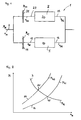
- the torque capacity or the maximum transmittable clutch torque M K2 of the first clutch 11 can via a starting characteristic 14, as shown in FIG. 2 is shown, are set in dependence of the engine speed n M.
- the starting characteristic 14 of FIG. 2 increases monotonously steadily with increasing engine speed n M. As far as an applied to the crankshaft 2 engine torque M M is greater than the torque capacity or the transmittable clutch torque M K1 , transmits the first clutch 11 exactly this clutch torque M K1 on the input shaft 12 of the partial transmission 10th
- FIG. 2 further shows a starting characteristic 24, which shows the maximum transferable clutch torque M K2 of the second clutch 21 as a function of the engine speed n M.
- the start-up characteristics 14, 24 depend on the engaged gear I, II of the respective partial transmission 10, 20 from. For example, if in the first partial transmission 10 other than the first forward gear I is engaged, then a completely different dependence of the clutch torque M K1 of the first clutch 11 may be deposited.
- FIG. 2 shows an engine characteristic curve M M of a specific engine load (for example 40% of the full load) or of a specific engine torque M M.
- the motor characteristic curve 3 intersects the starting characteristic curves 14, 24 at points of intersection 15, 25. At the intersection point 15, the gradient of the starting characteristic 14 is greater than the gradient of the motor characteristic curve 3. The same applies to the point of intersection 25.
- FIG. 3 shows various speed curves over time t for a shift of the invention from the first gear I to second gear II.
- the vehicle is stationary and the engine rotates at idle speed n 0 .
- a certain engine load is set, so that the engine speed n M (thick solid line) increases starting from the time t 0 .
- the starting characteristic 14 cf. FIG. 2
- the transmittable clutch torque M K1 is greater, so that the vehicle is further accelerated.
- the engine speed n M thereby runs along a characteristic n M1 (dashed line), which equals the speed n E1 as the time progresses.
- the characteristic curve n M1 thus indicates the profile of the engine speed n M when not switched when starting the vehicle and the vehicle is first accelerated with the first gear until the engine speed n M of the rotational speed n E1 of the first input shaft 12 and the clutch 11 works without slippage.
- the clutch torque of the first clutch 11 is reduced by means of a degradation function F Ab
- the clutch torque M k2 of the second clutch 21 is constructed via a body function F Auf .
- the construction function F up and the removal function F Ab are functions that are linear with respect to time t, with their gradients being dimensioned in another time t 2, it assumes the value 0 (applies to the degradation function F Ab ) or the value 1 (applies to the build-up function F Up ).
- the clutch torque M k1 of the first clutch 11 is reduced to a value 0 from a torque starting value which is applied to the first clutch 11 at time t 1 .
- the clutch torque M k2 of the second clutch 21 is built up from the value 0 at time t 1 to a value M k2 , which corresponds to a Drehmomentendwert at which the second gear and the engine speed dependent starting characteristic 24, the motor characteristic. 3 the predetermined engine load cuts. Accordingly, the engine speed n M runs at the time t 2 in the characteristic n M2 , which represents the engine speed, if it would be approached only with the second gear.
- the engine speed n M intersects the speed n E1 of the first input shaft 12. This means that the engine rotates slower than the first input shaft 12. If, after time t 2 , the first clutch 11 continues to transmit torque, the engine brakes Motor from the first input shaft 12, while it drives the second input shaft 22 via the second clutch 21. This would lead to a distortion of the dual-clutch transmission 1, but this is accompanied within certain limits without loss of comfort. If there is greater tension, this can be compensated by increasing the engine torque M M.
- FIG. 4 shows a flowchart for calculating the torque capacity or clutch torque M k1 and M k2 of the clutches 11, 21.
- the clutch torque of the first clutch according to the starting characteristic 14 certainly.
- the clutch torque depends on the engine speed n M , but may also depend on other factors such as the speed n E1 of the input shaft 12, the speed n E2 of the second input shaft 22, the time t and the speed v of the vehicle.
- the torque calculation takes place in accordance with starting characteristic 24 (cf. FIG. 2 ) for the second clutch 21 (see block 26 in FIG. 4 ).
- the degradation function F Ab is determined, which is performed linearly with time t from a start value 1 time t 1 to a final value 0 at time t 2 .
- the clutch torque of the first clutch 12 according to the starting characteristic 14 and the degradation function F Ab are multiplied in the link 17 with each other, wherein the product resulting from this link 17 the coupling torque M k1 of first clutch 12 during the shift corresponds.
- the clutch torque M k2 of the second clutch 22 is calculated by multiplying the torque according to start-up characteristic 24 and the build-up function F Auf in a link 27.
- the construction function F Auf corresponds to the difference 1 - F Ab .
- FIG. 5 shows different speed curves of a further embodiment of the invention.
- An essential difference to the embodiment according to FIG. 3 consists in that an adaptation of the engine speed n M to the speed n E2 of the second input shaft 22 takes place only after a time t 4 .
- the second clutch 21 is guided to an intermediate value M ZW , wherein the engine speed n M further corresponds to the rotational speed of the first input shaft 12.
- the flowchart of FIG. 6 can also be removed, again on the degradation function F Ab and on the build function F on .
- the functions F Ab , F On are also linearly dependent on the time t.
- the intermediate value M ZW and the clutch torque according to the starting characteristic 24 may depend on the engine speed n M , the rotational speeds n E1 , n E2 of the input shafts 12, 22, the speed v of the vehicle, the time t and / or the driver's desired torque M W.
- the multiplication of the intermediate value M ZW and the degradation function F Ab takes place in the flowchart of FIG FIG. 6 in a link 28.
- the summands described above are added in a link 29, the sum corresponding to the clutch torque M k2 of the second clutch 22.
- the engine speed n M is adjusted starting from the time t 4 of the rotational speed n E1 of the first input shaft to the rotational speed n E2 of the second input shaft 22.
Applications Claiming Priority (1)
| Application Number | Priority Date | Filing Date | Title |
|---|---|---|---|
| DE102007057205 | 2007-11-26 |
Publications (2)
| Publication Number | Publication Date |
|---|---|
| EP2063152A1 true EP2063152A1 (fr) | 2009-05-27 |
| EP2063152B1 EP2063152B1 (fr) | 2011-02-02 |
Family
ID=40342610
Family Applications (1)
| Application Number | Title | Priority Date | Filing Date |
|---|---|---|---|
| EP08105379A Active EP2063152B1 (fr) | 2007-11-26 | 2008-09-18 | Procédé de commutation d'un engrenage d'embrayage double |
Country Status (3)
| Country | Link |
|---|---|
| US (1) | US8177685B2 (fr) |
| EP (1) | EP2063152B1 (fr) |
| DE (1) | DE502008002519D1 (fr) |
Cited By (2)
| Publication number | Priority date | Publication date | Assignee | Title |
|---|---|---|---|---|
| WO2012143022A1 (fr) * | 2011-04-20 | 2012-10-26 | Audi Ag | Procédé permettant de faire fonctionner un véhicule automobile en poussée |
| CN107599891A (zh) * | 2017-08-31 | 2018-01-19 | 北京新能源汽车股份有限公司 | 挡位切换方法和装置 |
Families Citing this family (10)
| Publication number | Priority date | Publication date | Assignee | Title |
|---|---|---|---|---|
| JP5017450B2 (ja) * | 2008-03-31 | 2012-09-05 | アイシン・エーアイ株式会社 | ハイブリッド動力装置 |
| DE102008040692A1 (de) * | 2008-07-24 | 2010-01-28 | Robert Bosch Gmbh | Verfahren und Vorrichtung zum Anfahren eines Hybridfahrzeuges |
| DE102010018532B3 (de) * | 2010-04-27 | 2011-07-07 | GETRAG FORD Transmissions GmbH, 50735 | Verfahren zum Schalten eines Doppelkupplungsgetriebes |
| DE102010044906A1 (de) * | 2010-09-09 | 2012-03-15 | Robert Bosch Gmbh | Verfahren zum Vergeben eines Betriebspunktes einer Antriebsmaschine eines Antriebssystems |
| KR101896149B1 (ko) | 2012-07-24 | 2018-09-07 | 디티아이 그룹 비.브이. | 변속기 시스템 |
| EP2899422B1 (fr) * | 2012-09-19 | 2022-06-08 | Yamaha Hatsudoki Kabushiki Kaisha | Dispositif de commande de véhicule, véhicule et moteur |
| KR101786126B1 (ko) * | 2012-10-26 | 2017-10-17 | 현대자동차주식회사 | 변속기 장착 ev차량의 모터토크 제어방법 |
| JP6512638B2 (ja) * | 2016-07-25 | 2019-05-15 | トヨタ自動車株式会社 | 車両の制御装置 |
| US10696289B2 (en) * | 2017-02-14 | 2020-06-30 | Ford Global Technologies, Llc | Systems and methods for meeting wheel torque demand in a hybrid vehicle |
| IT201900017543A1 (it) * | 2019-09-30 | 2021-03-30 | Ferrari Spa | Metodo di controllo per l'esecuzione di un cambio marcia ascendente con pedale dell'acceleratore rilasciato in una trasmissione provvista di un cambio servoassistito a doppia frizione |
Citations (4)
| Publication number | Priority date | Publication date | Assignee | Title |
|---|---|---|---|---|
| EP1507103B1 (fr) | 2003-08-14 | 2006-04-05 | Getrag Ford Transmissions GmbH | Procédé de passage entre deux embrayages |
| DE602005000435T2 (de) * | 2004-07-16 | 2007-05-16 | Nissan Motor Co., Ltd., Yokohama | Doppelkupplungsgetriebe und Schaltverfahren für ein solches Getriebe |
| WO2007124710A1 (fr) * | 2006-04-28 | 2007-11-08 | Luk Lamellen Und Kupplungsbau Beteiligungs Kg | Procédé et dispositif pour adapter la commande des embrayages d'une transmission à double embrayage |
| EP1855021A1 (fr) * | 2006-04-29 | 2007-11-14 | Dr.Ing. h.c.F. Porsche Aktiengesellschaft | Procédé de démarrage pour moteurs à combustion interne dotés d'un engrenage à double embrayage |
Family Cites Families (4)
| Publication number | Priority date | Publication date | Assignee | Title |
|---|---|---|---|---|
| US7351183B2 (en) * | 2004-12-16 | 2008-04-01 | Ford Global Technologies, Llc | Ratio shift control for a multiple ratio automatic transmission |
| JP4169029B2 (ja) * | 2005-11-22 | 2008-10-22 | トヨタ自動車株式会社 | 車両用自動変速機の変速制御装置 |
| JP4278665B2 (ja) * | 2006-07-18 | 2009-06-17 | ジヤトコ株式会社 | 自動変速機の変速制御装置及び方法 |
| US7722499B2 (en) * | 2007-06-07 | 2010-05-25 | Ford Global Technologies, Llc | Launch control of a hybrid electric vehicle |
-
2008
- 2008-09-18 DE DE502008002519T patent/DE502008002519D1/de active Active
- 2008-09-18 EP EP08105379A patent/EP2063152B1/fr active Active
- 2008-11-19 US US12/274,284 patent/US8177685B2/en active Active
Patent Citations (4)
| Publication number | Priority date | Publication date | Assignee | Title |
|---|---|---|---|---|
| EP1507103B1 (fr) | 2003-08-14 | 2006-04-05 | Getrag Ford Transmissions GmbH | Procédé de passage entre deux embrayages |
| DE602005000435T2 (de) * | 2004-07-16 | 2007-05-16 | Nissan Motor Co., Ltd., Yokohama | Doppelkupplungsgetriebe und Schaltverfahren für ein solches Getriebe |
| WO2007124710A1 (fr) * | 2006-04-28 | 2007-11-08 | Luk Lamellen Und Kupplungsbau Beteiligungs Kg | Procédé et dispositif pour adapter la commande des embrayages d'une transmission à double embrayage |
| EP1855021A1 (fr) * | 2006-04-29 | 2007-11-14 | Dr.Ing. h.c.F. Porsche Aktiengesellschaft | Procédé de démarrage pour moteurs à combustion interne dotés d'un engrenage à double embrayage |
Cited By (5)
| Publication number | Priority date | Publication date | Assignee | Title |
|---|---|---|---|---|
| WO2012143022A1 (fr) * | 2011-04-20 | 2012-10-26 | Audi Ag | Procédé permettant de faire fonctionner un véhicule automobile en poussée |
| CN103477128A (zh) * | 2011-04-20 | 2013-12-25 | 奥迪股份公司 | 用于在减速滑行中运行机动车的方法 |
| US9126481B2 (en) | 2011-04-20 | 2015-09-08 | Audi Ag | Method for operating a motor vehicle in trailing throttle mode |
| CN103477128B (zh) * | 2011-04-20 | 2016-02-10 | 奥迪股份公司 | 用于在减速滑行中运行机动车的方法 |
| CN107599891A (zh) * | 2017-08-31 | 2018-01-19 | 北京新能源汽车股份有限公司 | 挡位切换方法和装置 |
Also Published As
| Publication number | Publication date |
|---|---|
| US8177685B2 (en) | 2012-05-15 |
| US20090137363A1 (en) | 2009-05-28 |
| EP2063152B1 (fr) | 2011-02-02 |
| DE502008002519D1 (de) | 2011-03-17 |
Similar Documents
| Publication | Publication Date | Title |
|---|---|---|
| EP2063152B1 (fr) | Procédé de commutation d'un engrenage d'embrayage double | |
| DE112007000849B4 (de) | Verfahren und Vorrichtung zum Adaptieren der Steuerung der Kupplungen eines Doppelkupplungsgetriebes | |
| DE602004000650T2 (de) | Steuerverfahren für ein Doppelkupplungsgetriebe | |
| EP0670789B1 (fr) | Procede permettant de moduler le couple de sortie d'une boite de vitesses automatique | |
| EP1564446B1 (fr) | Méthode et dispostif de commande de changement de vitesse pour transmission véhiculaire à changement parallèle | |
| EP2619482B1 (fr) | Procédé de commande de changements de vitesse d'une boîte de vitesses de véhicule | |
| WO2005019676A1 (fr) | Procede de commande d'une transmission a embrayage double | |
| DE10349220B4 (de) | Verfahren zum Schalten eines Doppelkupplungsgetriebes eines Kraftfahrzeuges | |
| WO2003074907A2 (fr) | Boite de vitesses a double embrayage et procede permettant d'effecteur un changement de vitesse dans une boite de vitesses a double embrayage | |
| DE102014208557B4 (de) | Verfahren zur Steuerung und/oder Regelung der Schaltung eines Doppelkupplungsgetriebes eines Kraftfahrzeugs | |
| EP1357309B1 (fr) | Méthode pour commander la procédure de démarrage d'une boîte de vitesse à double embrayage | |
| EP1455108A1 (fr) | Procédé pour contrôller un embrayage | |
| EP1382479B1 (fr) | Méthode de démarrage d'un système de transmission de véhicule avec une boîte de vitesse à double embrayage | |
| EP1950462B1 (fr) | Procédé de commande d'une unité d'entrainement comprenant une boîte de vitesses et un moteur | |
| DE112008000375B4 (de) | Verfahren und Vorrichtung zum Steuern der Kupplungen eines Parallelschaltgetriebes bei einem Gangwechsel | |
| WO2002095268A1 (fr) | Systemes de boite de vitesses | |
| DE19903554C2 (de) | Kraftfahrzeug-Antriebsstrang und Verfahren zu seiner Steuerung | |
| EP0992715B1 (fr) | Boíte de vitesses à rapports étagés ainsi qu'une procédure pour le dégagement d'un rapport d'une telle boíte de vitesses | |
| DE10247970A1 (de) | Verfahren zum Anfahren eines Kraftfahrzeuges | |
| WO2005008103A1 (fr) | Procede de commutation d'une boite de vitesses a double embrayage d'automobile | |
| DE102005034525A1 (de) | Kraftfahrzeug-Getriebeeinrichtung sowie Verfahren zur Steuerung eines Kraftfahrzeuges, und insbesondere zur Steuerung einer Getriebeeinrichtung eines Kraftfahrzeuges | |
| DE10261723B4 (de) | Verfahren zur Adaptation einer Schaltkennlinie einer Lastschaltkupplung eines Kraftfahrzeuggetriebes | |
| AT508077B1 (de) | Verfahren zum betreiben eines ein lastschalt-wendegetriebe aufweisenden kraftfahrzeuges | |
| EP1351836A1 (fr) | Procede pour commander et reguler une transmission | |
| EP3550169B1 (fr) | Procédé de commande et / ou de régulation de l'embrayage double d'une boîte de vitesses à double embrayage d'un véhicule automobile |
Legal Events
| Date | Code | Title | Description |
|---|---|---|---|
| PUAI | Public reference made under article 153(3) epc to a published international application that has entered the european phase |
Free format text: ORIGINAL CODE: 0009012 |
|
| AK | Designated contracting states |
Kind code of ref document: A1 Designated state(s): AT BE BG CH CY CZ DE DK EE ES FI FR GB GR HR HU IE IS IT LI LT LU LV MC MT NL NO PL PT RO SE SI SK TR |
|
| AX | Request for extension of the european patent |
Extension state: AL BA MK RS |
|
| 17P | Request for examination filed |
Effective date: 20091127 |
|
| 17Q | First examination report despatched |
Effective date: 20091223 |
|
| AKX | Designation fees paid |
Designated state(s): DE FR GB |
|
| GRAP | Despatch of communication of intention to grant a patent |
Free format text: ORIGINAL CODE: EPIDOSNIGR1 |
|
| GRAS | Grant fee paid |
Free format text: ORIGINAL CODE: EPIDOSNIGR3 |
|
| GRAA | (expected) grant |
Free format text: ORIGINAL CODE: 0009210 |
|
| AK | Designated contracting states |
Kind code of ref document: B1 Designated state(s): DE FR GB |
|
| REG | Reference to a national code |
Ref country code: GB Ref legal event code: FG4D Free format text: NOT ENGLISH |
|
| REF | Corresponds to: |
Ref document number: 502008002519 Country of ref document: DE Date of ref document: 20110317 Kind code of ref document: P |
|
| REG | Reference to a national code |
Ref country code: DE Ref legal event code: R096 Ref document number: 502008002519 Country of ref document: DE Effective date: 20110317 |
|
| PLBE | No opposition filed within time limit |
Free format text: ORIGINAL CODE: 0009261 |
|
| STAA | Information on the status of an ep patent application or granted ep patent |
Free format text: STATUS: NO OPPOSITION FILED WITHIN TIME LIMIT |
|
| 26N | No opposition filed |
Effective date: 20111103 |
|
| REG | Reference to a national code |
Ref country code: DE Ref legal event code: R097 Ref document number: 502008002519 Country of ref document: DE Effective date: 20111103 |
|
| REG | Reference to a national code |
Ref country code: FR Ref legal event code: PLFP Year of fee payment: 9 |
|
| REG | Reference to a national code |
Ref country code: FR Ref legal event code: PLFP Year of fee payment: 10 |
|
| REG | Reference to a national code |
Ref country code: FR Ref legal event code: PLFP Year of fee payment: 11 |
|
| PGFP | Annual fee paid to national office [announced via postgrant information from national office to epo] |
Ref country code: DE Payment date: 20190813 Year of fee payment: 12 |
|
| PGFP | Annual fee paid to national office [announced via postgrant information from national office to epo] |
Ref country code: GB Payment date: 20190827 Year of fee payment: 12 |
|
| REG | Reference to a national code |
Ref country code: DE Ref legal event code: R119 Ref document number: 502008002519 Country of ref document: DE |
|
| GBPC | Gb: european patent ceased through non-payment of renewal fee |
Effective date: 20200918 |
|
| PG25 | Lapsed in a contracting state [announced via postgrant information from national office to epo] |
Ref country code: DE Free format text: LAPSE BECAUSE OF NON-PAYMENT OF DUE FEES Effective date: 20210401 |
|
| PG25 | Lapsed in a contracting state [announced via postgrant information from national office to epo] |
Ref country code: GB Free format text: LAPSE BECAUSE OF NON-PAYMENT OF DUE FEES Effective date: 20200918 |
|
| PGFP | Annual fee paid to national office [announced via postgrant information from national office to epo] |
Ref country code: FR Payment date: 20230928 Year of fee payment: 16 |