EP2063023A2 - Device and method for changing a fabric of a paper machine - Google Patents
Device and method for changing a fabric of a paper machine Download PDFInfo
- Publication number
- EP2063023A2 EP2063023A2 EP08169104A EP08169104A EP2063023A2 EP 2063023 A2 EP2063023 A2 EP 2063023A2 EP 08169104 A EP08169104 A EP 08169104A EP 08169104 A EP08169104 A EP 08169104A EP 2063023 A2 EP2063023 A2 EP 2063023A2
- Authority
- EP
- European Patent Office
- Prior art keywords
- fabric
- paper machine
- cylinder
- clothing
- chair
- Prior art date
- Legal status (The legal status is an assumption and is not a legal conclusion. Google has not performed a legal analysis and makes no representation as to the accuracy of the status listed.)
- Withdrawn
Links
Images


Classifications
-
- D—TEXTILES; PAPER
- D21—PAPER-MAKING; PRODUCTION OF CELLULOSE
- D21F—PAPER-MAKING MACHINES; METHODS OF PRODUCING PAPER THEREON
- D21F7/00—Other details of machines for making continuous webs of paper
- D21F7/001—Wire-changing arrangements
Definitions
- the invention relates to a device for changing a fabric of a paper machine, a method for changing the clothing and a clothing itself.
- a device which comprises a plurality of individual rollers, which served essentially to assist the collection of the clothing.
- a disadvantage of the FI-B-103421 was that the device to support the collection of the clothing included a variety of individual roles and thus items. Furthermore, had from the FI-B-103421 known roles the disadvantage of high surface pressure.
- the changing device according to the WO 2006/106178 includes a first device with a frame, a pressure chamber and a circulating belt as well as a second device of the same construction arranged under this first device.
- Each of the two devices has a pressure chamber.
- the frames of the pressure chamber absorb the forces of the upper and lower parts of the stool.
- the bands of the device are not loaded.
- a change of clothing is to be carried out, pressure is introduced into the pressure chambers.
- the introduced pressure in the pressure chamber causes the load, which was loaded on the frame in the operating state, to be transmitted to the belts and the pressure chambers.
- the frame members are thereby separated from each other as the load is transmitted from the frame members to the pressure chambers and the bands.
- a gap is created between the frame or the upper part of the chair and the lower part of the chair, through which the covering can be threaded.
- the pressure introduced into the pressure chambers is also utilized so that the introduced band can slide substantially without friction. If the fabric is guided during the change in the resulting gap between the bands of the device, the fabric can be introduced by means of the bands in the device, for example, in that a drive motor is coupled to at least one roller of the device.
- a disadvantage of the device according to the WO 2006/106178 was that the fabric could only be pulled in with the help of a lubricant without damaging the fabric.
- the object of the invention is therefore to provide a solution for a string changing device, with the disadvantages of the prior
- the technique can be avoided and with the a change of clothing without complicated further measures as in the WO 2006/106178 described, can be performed.
- the use of a lubricant should be avoided.
- a device for changing a fabric in a paper machine with a stiffening at least a first and a second half of the staging has at least a first means for applying a flat pressure on the fabric is provided and a second means for applying a flat counterpressure on the fabric, so that by applying the sheet pressure, the first and the second half of the stiffener are pressed apart and a chair opening is provided for Beschreibs CAD available and further provided at least a third means with which the fabric in a horizontal direction along the opening of the chair can be moved.
- the first device is also referred to as a top unit and the second device as a subunit.
- the first device preferably comprises a cylinder, which is supported by a support device on the first half of the chair.
- the cylinder may preferably be a hydraulic, pneumatic or electric cylinder.
- the support a slide bearing plate.
- the second support device is designed as a sliding bearing plate.
- the third device for moving the clamped-in clothing approximately horizontally in the direction of the opening of the strangulation comprises a further cylinder, which in turn may be designed as a hydraulic, pneumatic or electric cylinder.
- the first device comprises a cylinder, which is supported by a support device on the first half of the chair and connected to a pressure plate which can apply the surface pressure on the fabric.
- the first device opposite the second device again has a counter-plate, which is supported by a further support means on the second half of the chair.
- This further support means may in turn comprise a cylinder.
- a flat pressure can be applied to the fabric over a plate. If now the cylinder of the first device extended, the stench is raised. The clothing can now be changed.
- a horizontal process can be done by another cylinder.
- the changing device according to the invention is used in a paper machine with a press and / or wire section for changing screens or felts use.
- the invention also provides a method for drawing a string.
- the method first the fabric is stretched in front of the paper machine. Then, with the aid of the first device, the upper and lower half of the stiffener are pushed apart.
- the weight of the upper half of the stool is then transferred with their superstructures over the fabric to the lower half of the stiffener.
- the invention also shows a clothing with means that avoid damage during insertion or execution.
- the fabric had lateral insertion and removal aids.
- FIG. 1 is a side view of a section of a paper machine shown, for example, a press section.
- the individual elements of the press section are received by a chair 10. Furthermore, the circumferential covering, for example a felt in the press section of the paper machine, can be seen. In the present embodiment, only the peripheral top felt 20 is completely shown, the circumferential bottom felt 22 only partially. How out FIG. 1 to see, in order to exchange the top felt 20, the connection of the individual parts of the chair 10.1, 10.2, be solved and the individual parts of the chair 10.1, 10.2 be raised, so that there are openings 30.1, 30.2, 30.3, through which the fabric at a change can be passed.
- the stool openings are generally provided on the leader side of the paper machine by incorporating cantilever or flex beams extending from the leader side to the drive side and beyond, in addition to the traverses, in the paper machine. Such carriers are in the schematic view according to FIG. 2 shown.
- the carriers 40.1, 40.2 required for raising the framing parts run from the driver's side 100 to the drive side 120 of the paper machine.
- the supports 40.1, 40.2 are in turn anchored with supports 110.1, 110.2 either on the ceiling or on the ground, so that the forces of the stasis on the supports in the ground or in the ceiling are introduced.
- the resulting on the concern of the wearer openings on the gnatulites are in FIG. 2 also shown.
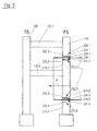
- FIG. 3 a schematic plan view of a paper machine or a part of a paper machine 100 from the driver side to the drive side.
- the leader side (FS) 110 is connected to the drive side (TS) 120 of the paper machine via traverse carrier 130.1, 130.2.
- TS drive side
- the device according to the invention is used to press apart the driver-side structural parts in the region of the device according to the invention with an upper and lower unit, so that an opening is made available. The fabric can then be inserted into this opening.
- the upper units 212.1, 212.3 for applying a flat pressure to the clothing comprise a first device, preferably a hydraulically raisable and lowerable cylinder 214.1, 214.2.
- the cylinders 214.1, 214.2 lowered and press surface on the fabric 216.1, 216.2.
- the clothing is then clamped between the cylinders 214.1, 214.2 and the counter plates 218.1, 218.2 opposite the cylinders.
- Both the upper units 212.1, 212.3 with cylinders 214.1, 214.2 and subunits 212.2, 212.4 are mounted on a slide plate 222.1, 222.2, 222.3, 222.4 and can be moved by means of, for example, another cylinder 224.1, 224.2 in a drawn horizontal direction H for pulling the fabric.
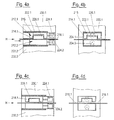
- FIGS. 4a and 4b show a first embodiment of the device according to the invention when pulling the fabric into the paper machine.
- the device is subdivided into an upper unit 212.1 and a subunit 212.2. Same components as in Figure 3 are marked with the same reference numbers.
- To pull in the clothing first the pressure chamber 215 of the cylinder 214.1 is subjected to a pressure medium.
- the piston 226.1 of the cylinder 214.1 extends, which causes the upper and the lower half of the suspension 230.1, 230.2 is pushed apart.
- the weight of the upper half of the cage with its superstructures is transferred in such a case on the fabric 216.1 on the lower half of the steamer.
- the collection of the clothing 216.1 in the paper machine is carried out in that the clamped clothing 216.1 together with the means for applying the counterforce, here the lower device 212.2 in the form of a so-called counter-plate or a counter-holder by means of additional cylinders 224.1, 224.2, as hydraulic -, electric or pneumatic cylinder can be designed, in the horizontal direction along the sliders 222.1, 222.2 slides and pulls in this way, the fabric a little way into the paper machine.
- FIGS. 4c to 4d show the process of the cylinders, which are responsible for the horizontal movement, in the starting position after the fabric has been fed into the paper machine.
- the piston 226.1 of the cylinder of the first device is raised, for example by the pressure medium being discharged in the pressure chamber.
- the piston is then no longer in contact with the fabric.
- the upper stiffening part 230.1 lowers onto the covering 216.1.
- the additional cylinders, the horizontal method of both the cylinder of the upper unit as well as the counter plate of the subunit in the FIGS. 4a and 4b are caused to be returned along the slide plate in their initial positions.
- the cylinder and the anvil are returned to the starting position, so the Einziehvorgang according to the FIGS. 4a and 4b start again. In this way, the entire clothing is successively pulled into the paper machine.
- the first device or the upper unit 312.1 comprises two cylinders 300.1, 305.1, which are fastened to a stiffening half 310.1.
- the other end of the cylinder is connected to a pressure plate 320.1, which can exert a surface-acting force on the fabric 316.
- the cylinder 300.1 essentially performs a vertical movement in the vertical direction V and the cylinder 305.1 substantially horizontal movement in the direction H.
- the cylinders 300.1, 305.1 of the first device which are connected to the upper half of the stool 310.1, are adjusted so that the pressure plate 320.1 does not come into contact with the fabric.
- the fabric itself is trapped between the printing plates 320.1, 330.1.
- the clothing clamped between the printing plates is now drawn into the paper machine by horizontal movement.
- the cylinder connected to the first half of the chair is retracted, whereby the first half of the chair is lowered onto the second half of the chair.
- the printing plates 320.1, 330.1 spent again in the starting position. Then the cycle can be repeated.
- the threading process can start anew.
- the stroke of the horizontally operating cylinder is preferably greater than the length of Printing plates. This has the advantage that during the first stroke the fabric can be gripped over the full surface of the printing plates with a stroke. As a result, a low stress on the clothing to be recovered is achieved.
- FIGS. 6a and 6b is an alternative embodiment of a second embodiment of the invention, as in the FIGS. 5a and 5b shown, shown.
- the same components are assigned the same reference numbers.
- the first device which is arranged on the upper half of the chair, is similar to the FIGS. 5a and 5b executed. She also works in an analogous way.
- a so-called Wälzwagen 400 is provided, which is characterized in that it comprises a plurality of rollers 405 which are connected to form an endless belt 410.
- the rollers 405 which are connected to form an endless belt 410, again wrapped around the entire circumference with a chain 420.
- the rollers rotate about a fixed core 425.
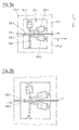
- FIGS. 7a to 7c is given a particularly preferred embodiment of the invention.
- Same components as in Fig. 4a to 4d are assigned the same reference numbers.
- the Design of a paper machine according to FIGS. 7a to 7c In addition, cylinder 500.1, 500.2 on, which can serve to lift the Friction parts.
- FIG. 7c shows the end of the threading process.
- the covering between the piston and the counterplate must be removed.
- cylinder 500.1 is extended and the upper and lower parts of the frame are pushed apart. Due to the resulting gap S, the fabric can be easily removed from the changing device.
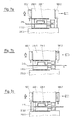
- FIGS. 8a to 8c an alternative embodiment of a Einziehvorganges is shown, in which can be dispensed with additional cylinder on the outside of the stiffening. Same components as in the FIGS. 4a to 4d are with the same reference numerals.
- the two parts of the framing are first pressed apart by pressurizing the piston in the cylinder at the separation point on the stiffening. It creates a gap in this way. Through this gap, the fabric to be changed can be pushed to the front of the piston 226.1, which rests on the back plate.
- the piston 226.1 retracted into the cylinder.
- the parting line between upper and lower stiffening closes and the weight of the entire stench lies on the covering 216.
- the surface of the parting line 600 is at least as large as that of the piston 226.1, in order to avoid that in the region of the parting line 600 a higher surface load on the clothing 216 is as in the area of the piston 226.1.
- FIG. 9 is a section along A - A in FIG. 8c shown. Clearly visible is the square shaped counter-plate, which exerts a surface-acting force on the fabric.
- the horizontally movable cylinder is designated 224.1.
- the parting line 600 in FIG. 8a is located to the leader's side offset to the left of the upper unit 214.1.
- Two separating joints 600.1, 600.2) are shown.
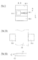
- FIGS. 10a-10b an alternative variant is shown, with which the covering can be protected, if at the beginning the covering can not be pulled completely under the lifting surface 320.1.
- FIG. 10a is shown how damage to the fabric especially at the first and last stroke for feeding alternatively to the in the FIGS. 7 to 9 described solutions, however, in contrast to FIG. 8a are not offset to the driver's side, but are parallel to the cylinder 224 in the machine direction P 1 or P 2 , can be avoided.
- an approximately equally thick piece 700.1, 700.2 of other clothing is stapled to the edge on both sides of the clothing 216.
- the other pieces 700.1, 700. 2 of the clothing are also referred to as lateral insertion and Ausfactudgen.
- the insertion and removal aids preferably have substantially the same thickness as the covering or the felt which is used in the paper machine, for example for dewatering.
- the stitched to the edge of the fabric felts can then be damaged when pulled by too high pressure, but this is not critical, since these parts can be removed again at the end of the pulling-in process for the fabric.
- FIG. 10a shows a plan view of a part of the fabric with laterally arranged input and Aus slaughter time
- FIG. 10b a sectional view. It can be clearly seen that the thickness of the fabric to the edge, ie to the input and export parts out, decreases, in the area in which the input and export parts are sewn to the fabric, but essentially matches.
- a device is specified for the first time, which allows to draw in a simple manner a stringing in a press or wire section, wherein the use of cantilevers is avoided.
Landscapes
- Treatment Of Fiber Materials (AREA)
Abstract
Description
Die Erfindung betrifft eine Vorrichtung zum Wechseln einer Bespannung einer Papiermaschine, ein Verfahren zum Bespannungswechsel und einer Bespannung selbst.The invention relates to a device for changing a fabric of a paper machine, a method for changing the clothing and a clothing itself.
Um eine endlose Bespannung, beispielsweise einen Filz für eine Pressenpartie oder ein Sieb für eine Siebpartie in die Papiermaschine einzuziehen, waren bislang in Papiermaschinen Cantilever- oder Biegeträger eingebaut, die von der Führerseite zur Triebseite und über die Triebseite hinaus reichten. Mit Hilfe der Cantilever- oder Biegeträger wurde die führerseitige Stuhlung zum Bespannungswechsel angehoben und Zwischenstücke entfernt, so dass Stuhlungsöffnungen entstanden sind, über die die Bespannung eingezogen werden konnte. Auch beim finnischen Patent
Um die Bespannung einziehen zu können, war bei der
Aus der
Beim Aufbau gemäß der
Im Betriebszustand nehmen die Rahmen der Druckkammer die Kräfte des oberen und des unteren Stuhlungsteils auf. Die Bänder der Vorrichtung sind nicht belastet.In operation, the frames of the pressure chamber absorb the forces of the upper and lower parts of the stool. The bands of the device are not loaded.
Soll ein Bespannungswechsel durchgeführt werden, so wird Druck in die Druckkammern eingeleitet. Der eingeleitete Druck in der Druckkammer führt dazu, dass die Last, die im Betriebszustand auf den Rahmen lastete, auf die Bänder und die Druckkammern übertragen wird. Die Rahmenteile werden dadurch voneinander separiert, und zwar in dem Maße, wie die Last von den Rahmenteilen auf die Druckkammern und die Bänder übertragen werden. Dies führt dazu, dass zwischen dem Rahmen beziehungsweise dem oberen Teil der Stuhlung und dem unteren Teil der Stuhlung ein Spalt entsteht, durch den die Bespannung eingefädelt werden kann. Um dies zu unterstützen, ist bei der
Nachteilig an der Vorrichtung gemäß der
Aufgabe der Erfindung ist es somit, eine Lösung für eine Bespannungswechselvorrichtung anzugeben, mit der die Nachteile des Standes der Technik vermieden werden und mit der ein Bespannungswechsel ohne aufwendige weitere Maßnahmen wie in der
Erfindungsgemäß wird diese Aufgabe dadurch gelöst, dass einer Vorrichtung zum Wechsel einer Bespannung in einer Papiermaschine mit einer Stuhlung die wenigstens eine erste und eine zweite Stuhlungshälfte aufweist wenigstens eine erste Einrichtung zum Aufbringen eines flächigen Druckes auf die Bespannung vorgesehen ist sowie eine zweite Einrichtung zum Aufbringen eines flächigen Gegendruckes auf die Bespannung, so dass durch Aufbringen des flächigen Druckes die erste und die zweite Stuhlungshälfte auseinander gedrückt werden und eine Stuhlungsöffnung zum Bespannungswechsel zur Verfügung gestellt wird und des Weiteren wenigstens eine dritte Einrichtung vorgesehen ist, mit der die Bespannung in einer horizontalen Richtung entlang der Stuhlungsöffnung bewegt werden kann.According to the invention this object is achieved in that a device for changing a fabric in a paper machine with a stiffening at least a first and a second half of the staging has at least a first means for applying a flat pressure on the fabric is provided and a second means for applying a flat counterpressure on the fabric, so that by applying the sheet pressure, the first and the second half of the stiffener are pressed apart and a chair opening is provided for Bespannungswechsel available and further provided at least a third means with which the fabric in a horizontal direction along the opening of the chair can be moved.
Bei einer derartigen Ausgestaltung der Erfindung ist es nicht mehr notwendig, eigene Biegeträger einzusetzen, um die Stuhlungsöffnungen bei einem Bespannungswechsel zu erzeugen. Ein weiterer Vorteil ist darin zu sehen, dass auf die Bespannung ein flächiger Druck aufgebracht wird, wodurch eine punktuelle Belastung der Bespannung vermieden wird. Die erste Einrichtung wird auch als Obereinheit und die zweite Einrichtung als Untereinheit bezeichnet.In such an embodiment of the invention, it is no longer necessary to use their own bending beams to produce the Förungsöffnungen at a change of clothing. Another advantage is the fact that a flat pressure is applied to the fabric, whereby a punctual loading of the fabric is avoided. The first device is also referred to as a top unit and the second device as a subunit.
In einer ersten Ausgestaltung der Erfindung umfasst bevorzugt die erste Einrichtung einen Zylinder, der sich über eine Abstützeinrichtung an der ersten Stuhlungshälfte abstützt. Der Zylinder kann bevorzugt ein Hydraulik-, Pneumatik-oder Elektrozylinder sein. In der ersten Ausgestaltung der Erfindung ist bevorzugt die Abstützung eine Gleitlagerplatte. Auf der anderen Seite der Bespannung befindet sich bevorzugt eine Gegenplatte, die sich über eine weitere Abstützeinrichtung an der zweiten Stuhlungshälfte abstützt. Bevorzugt ist auch die zweite Abstützeinrichtung als Gleitlagerplatte ausgebildet. Anstelle der Gleitlagerplatten können auch Rollen, Kugellager oder ähnliche Mittel verwendet werden. Bevorzugt umfasst die dritte Einrichtung zum Bewegen der eingeklemmten Bespannung näherungsweise horizontal in Richtung der Stuhlungsöffnung einen weiteren Zylinder, der wiederum als Hydraulik-, Pneumatik- oder Elektrozylinders ausgeführt sein kann.In a first embodiment of the invention, the first device preferably comprises a cylinder, which is supported by a support device on the first half of the chair. The cylinder may preferably be a hydraulic, pneumatic or electric cylinder. In the first embodiment of the invention is preferred the support a slide bearing plate. On the other side of the clothing is preferably a counter-plate, which is supported by a further support means on the second half of the chair. Preferably, the second support device is designed as a sliding bearing plate. Instead of plain bearing plates, rollers, ball bearings or similar means may be used. Preferably, the third device for moving the clamped-in clothing approximately horizontally in the direction of the opening of the strangulation comprises a further cylinder, which in turn may be designed as a hydraulic, pneumatic or electric cylinder.
In einer alternativen Ausführungsform einer Vorrichtung zum Bespannungswechsel umfasst die erste Einrichtung einen Zylinder, die sich über eine Abstützeinrichtung an der ersten Stuhlungshälfte abstützt und mit einer Druckplatte verbunden ist, die den flächigen Druck auf die Bespannung aufbringen kann. Bevorzugt weist die der ersten Einrichtung gegenüberliegende zweite Einrichtung wiederum eine Gegenplatte auf, die sich über eine weitere Abstützeinrichtung an der zweiten Stuhlungshälfte abstützt. Diese weitere Abstützeinrichtung kann wiederum einen Zylinder umfassen. Beispielsweise durch den Zylinder der ersten Einrichtung kann über eine Platte ein flächiger Druck auf die Bespannung aufgebracht werden. Wird nunmehr der Zylinder der ersten Vorrichtung ausgefahren, so wird die Stuhlung angehoben. Die Bespannung kann nunmehr gewechselt werden. Ein horizontales Verfahren kann durch einen weiteren Zylinder erfolgen.In an alternative embodiment of a device for changing the clothing, the first device comprises a cylinder, which is supported by a support device on the first half of the chair and connected to a pressure plate which can apply the surface pressure on the fabric. Preferably, the first device opposite the second device again has a counter-plate, which is supported by a further support means on the second half of the chair. This further support means may in turn comprise a cylinder. For example, by the cylinder of the first device, a flat pressure can be applied to the fabric over a plate. If now the cylinder of the first device extended, the stench is raised. The clothing can now be changed. A horizontal process can be done by another cylinder.
Bevorzugt findet die erfindungsgemäße Wechselvorrichtung in einer Papiermaschine mit einer Pressen- und/oder Siebpartie zum Wechsel von Sieben beziehungsweise Filzen Verwendung.Preferably, the changing device according to the invention is used in a paper machine with a press and / or wire section for changing screens or felts use.
Neben der Vorrichtung stellt die Erfindung auch ein Verfahren zum Einziehen einer Bespannung zur Verfügung. Bei dem Verfahren wird zunächst die Bespannung vor der Papiermaschine aufgespannt. Sodann wird mit Hilfe der ersten Einrichtung die obere und untere Stuhlungshälfte auseinander gedrückt.In addition to the device, the invention also provides a method for drawing a string. In the method, first the fabric is stretched in front of the paper machine. Then, with the aid of the first device, the upper and lower half of the stiffener are pushed apart.
Die Gewichtskraft der oberen Stuhlungshälfte wird dann mit ihren Aufbauten über die Bespannung übertragen auf die untere Stuhlungshälfte.The weight of the upper half of the stool is then transferred with their superstructures over the fabric to the lower half of the stiffener.
Durch Verfahren der geklemmten Bespannung im Wesentlichen in horizontaler Richtung des Stuhlungsspaltes von einer Ausgangsposition in eine Endposition wird die Bespannung sukzessive in den Stuhlungsspalt gezogen. Sodann wird durch Anheben der ersten Einrichtung der erste auf den zweiten Stuhlungsteil abgesenkt und die erfindungsgemäße Vorrichtung in die Ausgangsposition verbracht. Anschließend werden erneut die zuvor aufgeführten Schritte ausgeführt und so sukzessive die Bespannung eingezogen, bis die Bespannung vollständig von der Papiermaschine aufgenommen wird.By moving the clamped clothing essentially in the horizontal direction of the stiction gap from a starting position to an end position, the clothing is pulled successively into the stiction gap. Then, by lifting the first device, the first lowered to the second Fung part and spent the device according to the invention in the starting position. Subsequently, the steps listed above are carried out again and the fabric is successively pulled in until the clothing is completely taken up by the paper machine.
Da beim schrittweisen Einziehen der Bespannung, wie oben beschrieben, der Beginn und das Ende des Einziehvorganges immer kritisch ist und das Risiko von Beschädigungen der Bespannung vermieden werden soll, ist in einer weitergebildeten Ausführungsform vorgesehen, zusätzliche Zylinder an der Außen- und/oder Innenseite der führerseitigen Stuhlung anzubringen. Mit diesen Zylindern ist es dann möglich, bevor der erste Einziehhub ausgeführt wird, den oberen und unteren Teil der Stuhlung auseinanderzudrücken. Die Bespannung kann dann in dem Spalt nahezu vollflächig eingelegt werden. Anschließend wird der Einziehvorgang, wie zuvor beschrieben, sukzessive ausgeführt. Am Ende des Einziehvorganges wird wiederum der obere und untere Teil der Stuhlung mit Hilfe der zusätzlichen Zylinder auseinander gedrückt, so dass nunmehr die Bespannung leicht entnommen werden kann.As described in the stepwise retraction of the clothing, the beginning and end of the Einziehvorganges is always critical and the risk of damage to the fabric should be avoided, is provided in a further developed embodiment, additional cylinders on the outside and / or inside of to install on the driver side. With these cylinders, it is then possible, before the first Einziehhub is carried out to push apart the upper and lower part of the stoma. The fabric can then be inserted almost full-surface in the gap. Subsequently, the threading operation is successively performed as described above. At the end of the retraction process, in turn, the upper and lower part of the strangulation is pushed apart with the aid of the additional cylinders, so that now the clothing can be easily removed.
Neben der Vorrichtung zum Bespannungswechsel und dem Verfahren zum Bespannungswechsel zeigt die Erfindung auch noch eine Bespannung mit Mitteln, die eine Beschädigung beim Einführen oder Ausführen vermeiden. Hierzu wesit die Bespannung seitliche Ein- und Ausführhilfen auf.In addition to the apparatus for changing the clothing and the method for changing the clothing, the invention also shows a clothing with means that avoid damage during insertion or execution. For this purpose, the fabric had lateral insertion and removal aids.
Die Erfindung soll nachfolgend anhand der Ausführungsbeispiele und Figuren beschrieben werden, ohne hierauf beschränkt zu sein. Für den Fachmann versteht es sich, dass die oben genannten Einzelmaßnahmen untereinander kombiniert werden können, ohne vom Gedanken der Erfindung abzuweichen.The invention will be described below with reference to the embodiments and figures, without being limited thereto. For the expert understands it is that the above-mentioned individual measures can be combined with each other without deviating from the idea of the invention.
- Figur 1FIG. 1
- eine Seitenansicht einer Papiermaschine;a side view of a paper machine;
- Figur 2FIG. 2
- eine Draufsicht auf einen prinzipiellen Aufbau einer Papiermaschine mit einer Vorrichtung zum Anheben der Stuhlungsteile gemäß dem Stand der Technik;a plan view of a basic structure of a paper machine with a device for lifting the Stuhlungsteile according to the prior art;
- Figur 3FIG. 3
- eine Draufsicht auf eine Papiermaschine mit einer erfindungsgemäßen Vorrichtung zum Bespannungswechsel;a plan view of a paper machine with a device according to the invention for clothing change;
- Fig. 4a - 4dFig. 4a - 4d
- Detailansicht einer ersten Ausgestaltung einer erfindungsgemäßen Vorrichtung zum Wechseln einer Bespannung;Detailed view of a first embodiment of a device according to the invention for changing a fabric;
- Fig. 5a - 5bFig. 5a - 5b
- eine zweite Ausgestaltung einer erfindungsgemäßen Vorrichtung zum Wechseln einer Bespannung;a second embodiment of a device according to the invention for changing a fabric;
- Fig. 6a - 6bFig. 6a - 6b
- eine dritte Ausgestaltung einer erfindungsgemäßen Vorrichtung zum Wechseln einer Bespannung;a third embodiment of a device according to the invention for changing a fabric;
- Fig. 7a - 7cFig. 7a - 7c
- eine Weiterbildung einer ersten Ausgestaltung der Erfindung mit an der Stuhlung angebrachtem zusätzlichen Zylindern zum Wechseln einer Bespannung;a development of a first embodiment of the invention with attached to the stoma additional cylinders for changing a fabric;
- Fig. 8a - 8cFig. 8a - 8c
- eine detaillierte Ansicht des Einziehens einer Bespannung beim Beginn des Einziehens;a detailed view of the retraction of a fabric at the beginning of the retraction;
- Figur 9FIG. 9
-
eine Draufsicht auf eine Vorrichtung gemäß
Figur 8c entlang Schnitt A - A;a plan view of a device according toFIG. 8c along section A - A; - Figur 10a-bFigure 10a-b
- eine Ausgestaltung eines Filzes, um Beschädigungen zu vermeiden.an embodiment of a felt to avoid damage.
In
Die einzelnen Elemente der Pressenpartie werden von einer Stuhlung 10 aufgenommen. Des Weiteren zu erkennen ist die umlaufende Bespannung, beispielsweise ein Filz in der Pressenpartie der Papiermaschine. In vorliegender Ausführungsform ist lediglich der umlaufende Oberfilz 20 vollständig gezeigt, der umlaufende Unterfilz 22 nur abschnittsweise. Wie aus
Die zur Anhebung der Stuhlungsteile benötigten Träger 40.1, 40.2 verlaufen von der Führerseite 100 zur Triebseite 120 der Papiermaschine. Die Träger 40.1, 40.2 sind wiederum mit Stützen 110.1, 110,2 entweder an der Decke oder am Boden verankert, so dass die Kräfte der Stuhlung über die Stützen in den Boden beziehungsweise in die Decke eingeleitet werden. Die sich durch das Anliegen der Träger ergebenden Öffnungen auf der Führerseite sind in
Gemäß der Erfindung ist nun vorgesehen, dass für einen Bespannungswechsel auf ein Anheben einzelner Stuhlungsteile wie in
Erfindungsgemäß umfassen die Obereinheiten 212.1, 212.3 zum Aufbringen eines flächigen Druckes auf die Bespannung eine erste Einrichtung, vorzugsweise einen hydraulisch auf- und absenkbarer Zylinder 214.1, 214.2. In der dargestellten Ausführungsform sind die Zylinder 214.1, 214.2 abgesenkt und pressen flächig auf die Bespannung 216.1, 216.2. Die Bespannung wird dann zwischen den Zylindern 214.1, 214.2 und den den Zylindern gegenüberliegenden Gegenplatten 218.1, 218.2 eingeklemmt.. Sowohl die Obereinheiten 212.1, 212.3 mit Zylinder 214.1, 214.2 sowie Untereinheiten 212.2, 212.4 sind auf einer Gleitplatte 222.1, 222.2, 222.3, 222.4 gelagert und können mittels beispielsweise eines weiteren Zylinders 224.1, 224.2 in einer eingezeichneten horizontalen Richtung H zum Einziehen der Bespannung verschoben werden.According to the invention, the upper units 212.1, 212.3 for applying a flat pressure to the clothing comprise a first device, preferably a hydraulically raisable and lowerable cylinder 214.1, 214.2. In the illustrated embodiment, the cylinders 214.1, 214.2 lowered and press surface on the fabric 216.1, 216.2. The clothing is then clamped between the cylinders 214.1, 214.2 and the counter plates 218.1, 218.2 opposite the cylinders. Both the upper units 212.1, 212.3 with cylinders 214.1, 214.2 and subunits 212.2, 212.4 are mounted on a slide plate 222.1, 222.2, 222.3, 222.4 and can be moved by means of, for example, another cylinder 224.1, 224.2 in a drawn horizontal direction H for pulling the fabric.
Das Prinzip zum Einziehen der Bespannung, bei einer Verwendung einer Vorrichtung wie in
Die
Die
Eine alternative Ausgestaltung einer Vorrichtung zum Bespannungswechsel gemäß der Erfindung ist in den
In
Die Arbeitsweise der Ausführungsform gemäß den
In den
Bevorzugt geschieht dies am Beginn des Einziehvorganges. Um beim Beginn des Einziehvorganges die Bespannung 216 zwischen den Kolben und die Gegenplatte zu bringen, wobei die Bespannung vor dem ersten Einziehschritt zumindest nahezu vollständig zwischen Kolben und Gegenplatte zu liegen kommen sollte, können zwei zusätzliche Zylinder 500.1, 500.2 an der Außen- und Innenseite der führerseitigen Stuhlung angebracht werden. Der Zylinder 500.2 wird, bevor der erste Einziehhub ausgeführt wird, ausgefahren, so dass der untere Teil und der obere Teil der Stuhlung auseinander gedrückt. Sodann kann auf einfache Art und Weise die Bespannung zwischen Kolben 126.1 und Gegenplatte 212.2 weitgehend vollflächig gelegt werden. Hierdurch wird die Flächenpressung auf die Bespannung 216 minimiert und das Risiko einer Beschädigung vermindert, da die Last der Stuhlung sofort auf die maximal zur Verfügung stehende Fläche verteilt wird.This is preferably done at the beginning of the Einziehvorganges. In order to bring the covering 216 between the piston and the counter-plate at the beginning of the Einziehvorganges, the fabric should come to lie at least almost completely between the piston and counter-plate before the first Einziehschritt, two additional cylinders 500.1, 500.2 on the outside and inside of mounted on the driver's side. The cylinder 500.2, before the first Einziehhub is carried out, extended, so that the lower part and the upper part of the strangulation pressed apart. Then can be placed over the entire surface in a simple manner, the covering between the piston 126.1 and counter-plate 212.2. As a result, the surface pressure on the
Nachdem die Bespannung wie beschrieben in die Papiermaschine eingelegt wurde, wird der Zylinder 500.2 eingefahren. Nun kann der Einziehvorgang der gesamten Bespannung, wie in den
In den
Wie in
Ist der Kolben und die Gegenplatte über die Bespannung 216 verbracht, so wird der Kolben 226.1 beaufschlagt, und auf diese Art und Weise werden die Stuhlungsteile auseinander gedrückt. Es ergibt sich wieder ein Spalt S im Bereich der Trennfuge 600. Nunmehr werden wiederum der Kolben und das Gegenstück mit Hilfe der in horizontaler Richtung arbeitenden Zylinder entlang des Gleitstückes verschoben. Auf diese Art und Weise wird der Filz durch den Spalt S in Richtung der Papiermaschine 605 eingezogen. Die Reihenfolge des Einziehens ist detailliert bei den
In
In
Mit der Erfindung wird erstmals eine Vorrichtung angegeben, die es erlaubt, auf einfache Art und Weise eine Bespannung in eine Pressen- oder Siebpartie einzuziehen, wobei der Einsatz von Cantilevern vermieden wird.With the invention, a device is specified for the first time, which allows to draw in a simple manner a stringing in a press or wire section, wherein the use of cantilevers is avoided.
Claims (22)
die zweite Einrichtung eine Gegenplatte umfasst, die sich über eine weitere Abstützeinrichtung an der zweiten Stuhlungshälfte abstützt.Device according to one of claims 2 to 4, characterized in that
the second device comprises a counterplate, which is supported by a further support means on the second half of the chair.
die zweite Einrichtung eine Gegenplatte ist, die sich über eine weitere Abstützeinrichtung an der zweiten Stuhlungshälfte abstützt.Device according to one of claims 7 to 8, characterized in that
the second device is a counterplate, which is supported by a further support means on the second half of the chair.
die weitere Abstützung einen Zylinder umfasst.Device according to one of claims 9 to 11, characterized in that
the further support comprises a cylinder.
die Pressen- und/oder Siebpartie wenigstens eine Vorrichtung gemäß einem der Ansprüche 1 bis 13 zum Wechseln der Bespannung in der Pressen- und/oder Siebpartie aufweist.Paper machine with a press and / or wire section, characterized in that
the press and / or wire section at least one device according to one of claims 1 to 13 for changing the fabric in the press and / or wire section has.
dadurch gekennzeichnet, dass die Bespannung eine Längsseite umfasst und an wenigstens einer Längsseite seitlichen Einführ- und Ausführhilfe vorgesehen sind.Covering, in particular felt for use in a paper machine,
characterized in that the covering comprises a longitudinal side and are provided on at least one longitudinal side lateral insertion and execution assistance.
dadurch gekennzeichnet, dass die seitlichen Einführ- und Ausführhilfen Stücke (700.1, 700.2) der Bespannung mit im wesentlichen gleicher Dicke wie die Bespannung selbst sind.Fabric according to claim 20,
characterized in that the lateral insertion and removal aids are pieces (700.1, 700.2) of the fabric of substantially the same thickness as the fabric itself.
Applications Claiming Priority (1)
| Application Number | Priority Date | Filing Date | Title |
|---|---|---|---|
| DE102007047859A DE102007047859A1 (en) | 2007-11-26 | 2007-11-26 | Device for changing a fabric of a paper machine |
Publications (2)
| Publication Number | Publication Date |
|---|---|
| EP2063023A2 true EP2063023A2 (en) | 2009-05-27 |
| EP2063023A3 EP2063023A3 (en) | 2009-07-01 |
Family
ID=40386095
Family Applications (1)
| Application Number | Title | Priority Date | Filing Date |
|---|---|---|---|
| EP08169104A Withdrawn EP2063023A3 (en) | 2007-11-26 | 2008-11-14 | Device and method for changing a fabric of a paper machine |
Country Status (2)
| Country | Link |
|---|---|
| EP (1) | EP2063023A3 (en) |
| DE (1) | DE102007047859A1 (en) |
Cited By (7)
| Publication number | Priority date | Publication date | Assignee | Title |
|---|---|---|---|---|
| WO2011056113A1 (en) * | 2009-11-06 | 2011-05-12 | Metso Paper, Inc. | Apparatus for inserting or removing a clothing in an industrial machine |
| AT12472U1 (en) * | 2010-10-21 | 2012-06-15 | Metso Paper Inc | DEVICE FOR CHANGING A BELT IN A FIBERMAKING MACHINE AND A FIBERWORK MACHINE EMBODIED BY THIS DEVICE |
| CN103774484A (en) * | 2012-10-25 | 2014-05-07 | 美卓造纸机械公司 | Device for treating fibrous web |
| DE102015211300A1 (en) * | 2015-06-19 | 2016-05-25 | Voith Patent Gmbh | Device and method for introducing a clothing in a web forming machine |
| DE102016201895A1 (en) | 2016-02-09 | 2017-01-05 | Voith Patent Gmbh | Apparatus and method for changing a fabric of a paper machine |
| DE102016211359A1 (en) | 2016-06-24 | 2017-10-05 | Voith Patent Gmbh | Apparatus and method for changing a fabric of a paper machine |
| DE102016211360A1 (en) | 2016-06-24 | 2017-12-28 | Voith Patent Gmbh | Apparatus and method for changing a fabric of a paper machine |
Families Citing this family (1)
| Publication number | Priority date | Publication date | Assignee | Title |
|---|---|---|---|---|
| DE102015223661A1 (en) * | 2015-11-30 | 2017-05-18 | Voith Patent Gmbh | DEVICE FOR PRODUCING A FIBROUS WEB |
Citations (2)
| Publication number | Priority date | Publication date | Assignee | Title |
|---|---|---|---|---|
| FI103421B (en) | 1997-10-30 | 1999-06-30 | Valmet Corp | A method and apparatus for replacing tissue in a papermaking machine |
| WO2006106178A1 (en) | 2005-04-05 | 2006-10-12 | Metso Paper, Inc. | Method and device for changing a fabric in a paper or board machine |
Family Cites Families (2)
| Publication number | Priority date | Publication date | Assignee | Title |
|---|---|---|---|---|
| SE439652B (en) * | 1983-10-25 | 1985-06-24 | Nordiskafilt Ab | PAPER MACHINE FILTER ASSEMBLY |
| EP1820898A1 (en) * | 2006-02-20 | 2007-08-22 | Ichikawa Co.,Ltd. | Leader device for installing a belt in a paper machine and method for its manufacture |
-
2007
- 2007-11-26 DE DE102007047859A patent/DE102007047859A1/en not_active Withdrawn
-
2008
- 2008-11-14 EP EP08169104A patent/EP2063023A3/en not_active Withdrawn
Patent Citations (2)
| Publication number | Priority date | Publication date | Assignee | Title |
|---|---|---|---|---|
| FI103421B (en) | 1997-10-30 | 1999-06-30 | Valmet Corp | A method and apparatus for replacing tissue in a papermaking machine |
| WO2006106178A1 (en) | 2005-04-05 | 2006-10-12 | Metso Paper, Inc. | Method and device for changing a fabric in a paper or board machine |
Cited By (13)
| Publication number | Priority date | Publication date | Assignee | Title |
|---|---|---|---|---|
| WO2011056113A1 (en) * | 2009-11-06 | 2011-05-12 | Metso Paper, Inc. | Apparatus for inserting or removing a clothing in an industrial machine |
| CN102597368A (en) * | 2009-11-06 | 2012-07-18 | 梅特索纸业有限公司 | Apparatus for inserting or removing a clothing in an industrial machine |
| US8574401B2 (en) | 2009-11-06 | 2013-11-05 | Metso Paper, Inc. | Apparatus for inserting or removing a clothing in an industrial machine |
| CN102597368B (en) * | 2009-11-06 | 2014-12-17 | 梅特索纸业有限公司 | Method, apparatus for inserting or removing a clothing, application thereof, machine and improved method |
| AT12472U1 (en) * | 2010-10-21 | 2012-06-15 | Metso Paper Inc | DEVICE FOR CHANGING A BELT IN A FIBERMAKING MACHINE AND A FIBERWORK MACHINE EMBODIED BY THIS DEVICE |
| CN103774484A (en) * | 2012-10-25 | 2014-05-07 | 美卓造纸机械公司 | Device for treating fibrous web |
| DE102015211300A1 (en) * | 2015-06-19 | 2016-05-25 | Voith Patent Gmbh | Device and method for introducing a clothing in a web forming machine |
| DE102016201895A1 (en) | 2016-02-09 | 2017-01-05 | Voith Patent Gmbh | Apparatus and method for changing a fabric of a paper machine |
| DE102016211359A1 (en) | 2016-06-24 | 2017-10-05 | Voith Patent Gmbh | Apparatus and method for changing a fabric of a paper machine |
| DE102016211360A1 (en) | 2016-06-24 | 2017-12-28 | Voith Patent Gmbh | Apparatus and method for changing a fabric of a paper machine |
| WO2017220243A1 (en) | 2016-06-24 | 2017-12-28 | Voith Patent Gmbh | Apparatus and method for changing the clothing of a paper machine |
| CN108884636A (en) * | 2016-06-24 | 2018-11-23 | 福伊特专利有限公司 | For replacing the device and method of the stretching of paper machine |
| CN108884636B (en) * | 2016-06-24 | 2020-04-07 | 福伊特专利有限公司 | Device and method for changing a clothing of a paper machine |
Also Published As
| Publication number | Publication date |
|---|---|
| DE102007047859A1 (en) | 2009-05-28 |
| EP2063023A3 (en) | 2009-07-01 |
Similar Documents
| Publication | Publication Date | Title |
|---|---|---|
| EP0571581B1 (en) | Roll press | |
| EP2063023A2 (en) | Device and method for changing a fabric of a paper machine | |
| DE4110205C2 (en) | Roller press | |
| DE102007012174B4 (en) | Round baler and method for changing the friction on the side walls | |
| DE19717472A1 (en) | Method and device for profile bending with modular bending stations | |
| DE2943974C2 (en) | Press section of a paper machine | |
| DE69703095T2 (en) | CALENDAR WITH HIGH SPLIT PRESSURE | |
| EP3160726B1 (en) | Improved c-frame press | |
| DE102007047858A1 (en) | Device for changing a fabric of a paper machine | |
| DE4328505C2 (en) | Cantilever roller | |
| DE102006000324A1 (en) | Endless belt changing arrangement, especially for paper or cardboard machines, comprises transverse support removably inserted in receiver on stand construction | |
| DE2635010C2 (en) | Press for drying wet skins with endless, laterally removable felt belts | |
| DE682688C (en) | Multi-roll calender | |
| EP3475482B1 (en) | Apparatus and method for changing the clothing of a paper machine | |
| DE3242721C2 (en) | Wet press for dewatering a running fiber web | |
| DE8232424U1 (en) | Pressing device for dewatering a running fiber web | |
| DE19882820B4 (en) | Method and device for changing a round felt | |
| DE2049324B2 (en) | Continuous press, especially for squeezing fruits | |
| DE102016201895A1 (en) | Apparatus and method for changing a fabric of a paper machine | |
| DE102019122749A1 (en) | Straightening machine and method for making straightening rolls accessible for maintenance of a straightening machine | |
| DE1814066A1 (en) | Machine for bending sheet metal for the production of tubular bodies and a system equipped with such a machine | |
| WO2016034688A1 (en) | Continuously working press and method for operating presses of this type | |
| DE202017103053U1 (en) | Prepress and system for the continuous production of material plates and transport device for receiving the press belt | |
| DE3012852A1 (en) | Super calender conversion - has distance piece inserted in gap between rollers when unwanted upper rollers are lifted | |
| DE1928304A1 (en) | Paper machine press |
Legal Events
| Date | Code | Title | Description |
|---|---|---|---|
| PUAI | Public reference made under article 153(3) epc to a published international application that has entered the european phase |
Free format text: ORIGINAL CODE: 0009012 |
|
| AK | Designated contracting states |
Kind code of ref document: A2 Designated state(s): AT BE BG CH CY CZ DE DK EE ES FI FR GB GR HR HU IE IS IT LI LT LU LV MC MT NL NO PL PT RO SE SI SK TR |
|
| AX | Request for extension of the european patent |
Extension state: AL BA MK RS |
|
| PUAL | Search report despatched |
Free format text: ORIGINAL CODE: 0009013 |
|
| AK | Designated contracting states |
Kind code of ref document: A3 Designated state(s): AT BE BG CH CY CZ DE DK EE ES FI FR GB GR HR HU IE IS IT LI LT LU LV MC MT NL NO PL PT RO SE SI SK TR |
|
| AX | Request for extension of the european patent |
Extension state: AL BA MK RS |
|
| RIC1 | Information provided on ipc code assigned before grant |
Ipc: D21F 7/00 20060101AFI20090310BHEP |
|
| RTI1 | Title (correction) |
Free format text: DEVICE AND METHOD FOR CHANGING A FABRIC OF A PAPER MACHINE |
|
| 17P | Request for examination filed |
Effective date: 20100104 |
|
| 17Q | First examination report despatched |
Effective date: 20100208 |
|
| AKX | Designation fees paid |
Designated state(s): AT BE BG CH CY CZ DE DK EE ES FI FR GB GR HR HU IE IS IT LI LT LU LV MC MT NL NO PL PT RO SE SI SK TR |
|
| RIN1 | Information on inventor provided before grant (corrected) |
Inventor name: MUELLER, ANSGAR Inventor name: SCHMIDT, FRANK |
|
| GRAP | Despatch of communication of intention to grant a patent |
Free format text: ORIGINAL CODE: EPIDOSNIGR1 |
|
| STAA | Information on the status of an ep patent application or granted ep patent |
Free format text: STATUS: THE APPLICATION IS DEEMED TO BE WITHDRAWN |
|
| 18D | Application deemed to be withdrawn |
Effective date: 20130129 |