EP2062848A1 - Module de levage hydroélectrique - Google Patents
Module de levage hydroélectrique Download PDFInfo
- Publication number
- EP2062848A1 EP2062848A1 EP07022617A EP07022617A EP2062848A1 EP 2062848 A1 EP2062848 A1 EP 2062848A1 EP 07022617 A EP07022617 A EP 07022617A EP 07022617 A EP07022617 A EP 07022617A EP 2062848 A1 EP2062848 A1 EP 2062848A1
- Authority
- EP
- European Patent Office
- Prior art keywords
- consumer
- valve
- lifting module
- pressure
- supply line
- Prior art date
- Legal status (The legal status is an assumption and is not a legal conclusion. Google has not performed a legal analysis and makes no representation as to the accuracy of the status listed.)
- Granted
Links
Images
Classifications
-
- B—PERFORMING OPERATIONS; TRANSPORTING
- B66—HOISTING; LIFTING; HAULING
- B66F—HOISTING, LIFTING, HAULING OR PUSHING, NOT OTHERWISE PROVIDED FOR, e.g. DEVICES WHICH APPLY A LIFTING OR PUSHING FORCE DIRECTLY TO THE SURFACE OF A LOAD
- B66F9/00—Devices for lifting or lowering bulky or heavy goods for loading or unloading purposes
- B66F9/06—Devices for lifting or lowering bulky or heavy goods for loading or unloading purposes movable, with their loads, on wheels or the like, e.g. fork-lift trucks
- B66F9/075—Constructional features or details
- B66F9/20—Means for actuating or controlling masts, platforms, or forks
- B66F9/22—Hydraulic devices or systems
Definitions
- the invention relates to an electrohydraulic lifting module according to the preamble of patent claim 1.
- the 3/2-way pressure compensator for the main consumer is combined with a proportional pressure control directional control valve to a 3-way flow regulator, which regulates the supply of secondary consumers.
- This concept is expensive and complicated because of the 3-way current regulator.
- downstream of the 3-way flow regulator pressure should be present from a secondary consumer, an additional connection to the return required in order not to jeopardize the control function of the 3-way flow control.
- auxiliary consumers own pressure source.
- a 3-way current controller provided which regulates the supply of another secondary consumer. This concept is structurally complex and expensive.
- the 3-way flow control must be connected to an outlet to the return to run at back pressure from the downstream auxiliary consumers, the control function.
- each 3-way current regulator requires an expensive proportional magnet, which also has to be integrated into the electronics accordingly.
- the invention has for its object to provide an electro-hydraulic lifting module of the type mentioned, which is structurally simple and inexpensive to implement, ensures the required supply priority for the main consumer, and possibly also ensures priority for each subordinate auxiliary to a priority secondary consumer supply priority.
- the number of consumers corresponding number of 3/2-way pressure compensators as priority valves forms in Hubmodul a priority cascade that is structurally simple and cost-effective especially for industrial trucks and at least the main consumer supply priority guaranteed. This means that initially only the main consumer is supplied, as long as its needs are partially or completely covered by the pressure source. Only if the delivery rate of the pressure source exceeds the needs of the main consumer, at least one secondary consumer is also operable. If the capacity of the pressure source is sufficient to meet the needs of the main consumer and all secondary consumers, all auxiliary consumers can be operated together with the main consumer. In this priority cascade in each case the secondary consumer has priority, which is connected in the flow direction before another auxiliary consumer to the priority valve of the main consumer.
- the 3/2-way pressure compensators are cost-effective hydraulic elements that require no magnets or proportional solenoids for their function. Nevertheless, even a load pressure independent actuation of the main consumer and possibly the secondary consumer is possible on the 3/2-way pressure compensators.
- the lifting module is designed so that the secondary consumers in the row direction have decreasing flow rates.
- the main consumer needs a delivery rate of at least 60 l / min, while the delivery rates of the secondary consumers are, for example, 40, 15 and 5 l / min.
- all consumers can be actuated simultaneously occurs in a material handling vehicle usually only the need to operate in addition to a main consumer one or more than two secondary consumers at the same time, or, without the main consumer to operate, only one or two secondary consumers at the same time actuate.
- the accumulation pressures of the individual stages add up. However, this is insignificant in an industrial truck, since the control accuracy underneath sprübar does not suffer and the number of secondary consumers is limited anyway.
- the 3/2-way pressure compensators of the priority cascade for the main consumer and for the secondary consumers are identical or even identical. At most, the biases differ from the control springs of the 3/2-way pressure compensators. This principle of equality is inexpensive.
- the respective 3/2-way pressure compensator has in a settable by a control spring end position a direct flow path from the pressure source or the supply line (in the case of the auxiliary consumers) to the directional control valve and in a by control pressure of upstream the directional control valve and adjustable against the control spring, other end position a throttleable flow path from the pressure source or the supply line to the directional control valve and at the same time a direct second flow path from the pressure source or the supply line to another portion of the supply line. Only the direct second flow path of the rearmost auxiliary consumers in the series associated 3/2-way pressure compensator is connected to the return, so that the priority cascade, if the rearmost auxiliary consumer is not to operate, excess pressure fluid into the return line.
- each 3/2-way pressure compensator is acted upon by the control pressure downstream of the respective directional control valve and the control spring in the direction of the end position, in which a second output of the 3/2-way pressure compensator is shut off to the subsequent supply line section.
- the associated consumer main consumer or secondary consumer
- the associated consumer has supply priority with respect to each downstream consumer arranged in the flow direction.
- the directional control valves preferably solenoid or proportional solenoid operated, 2/2-way pressure control poppet valves or multi-way spool valves. These valves allow very precise control of the speeds of the loads and also the control of clean ramps when going from standstill to motion or when moving from a motion to a standstill.
- the directional valves are arranged in modular juxtaposed blocks, to which at the side of the pressure source in each case an input block is attached, at least the 3/2-way pressure compensator, each a portion of the supply line and a return and, preferably, a Contains pressure relief valve, the input blocks are also modular juxtaposed.
- This modular block design allows the optional design of differently designed electro-hydraulic lifting modules for different applications from individual components.
- each block and the input blocks could each form a block in which the directional control valve, the 3/2-way pressure compensator, a supply line section, a return section and the like are included.
- the main consumer is a lifting cylinder which acts simply against load
- a first secondary consumer is an initial lifting cylinder which acts simply against load
- a second secondary consumer comprises a pair of single-acting rotary cylinders
- a third secondary consumer is a sliding hydraulic motor.
- a maximum of four auxiliary consumers are controlled by the electro-hydraulic lifting module.
- This check valve is expediently arranged in the transition between two blocks or input blocks and separates the supply line sections in the return flow direction.
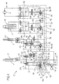
- FIG. 1 shows a block diagram of an electro-hydraulic lifting module for supplying here a main consumer H and three auxiliary consumers N1 to N3, the working components of an unspecified forklift truck, such as a forklift or rack stacker, or the like .. are.
- the electrohydraulic lifting module S in Fig. 1 is composed of four blocks 39, 40, 41 and 42, to each of which input blocks 43, 44, 45 and 46 are attached. In an alternative, not shown, the blocks and the input blocks may each be combined into a block.
- a driven by a motor M pump P forms the common pressure source for all consumers H, N1 to N3.
- the main consumer H is a lifting cylinder 1 which acts simply against load.
- the first secondary consumer N1 following the main consumer H is, for example, an initial stroke cylinder which acts simply against load.
- the next, second auxiliary consumer N2 consists for example of a pair of motion-coupled, single-acting rotary cylinder 3.
- the last or rearmost auxiliary consumer N3 is for example a sliding hydraulic motor. 4
- a pump line 5 branches off at a node 6 in the input block 43 with a connecting line 8 to a return line 9 to the return line R, wherein in the connecting line 8, a system pressure relief valve 7 is included.
- a first priority valve P1 is arranged in the pump line 5 for supplying the main consumer H, which is designed as a 3/2-way pressure compensator 10 and contains a control 11 which is connected between an inlet connection 12 and two outlet connections 14, 15 working regulates. Via a control line 19 upstream control valve 22 (lift valve, 2/2-way pressure control poppet valve with solenoid actuation) control pressure is tapped, which acts via a throttle 21, the control 11 of the 3/2-way pressure compensator in the direction of an end position.
- upstream control valve 22 lift valve, 2/2-way pressure control poppet valve with solenoid actuation
- a supply line 33 is connected, which consists of successive supply line sections 33a, 33b, 33c, wherein between the supply line sections further priority valves P2, P3, P4, each in the form of a 3/2-way Pressure compensator 10a, 10b, 10c are used.
- the priority valves P1 to P4 form in the electrohydraulic lifting module S a priority cascade and are, preferably, identical or even identical.
- the pump line 5 leads downstream of the check valve 24 to a node 23 in a working line 25 of the main consumer H.
- the working line 25 branches off at node 23 in a drain line 26, in which another directional control valve 27 vertically (2/2-way pressure control Poppet valve with proportional solenoid operation) is arranged.
- a 3/2-way pressure compensator 28 is arranged in the drain line 26, from which the drain line 26 into a Nutzsenktechnisch 31 to the suction side of the pump P (hedged by a check valve 32) and into a drain line 30 to the return R. branched.
- a 2/2-way pressure compensator 29 is included in the discharge line 30, a 2/2-way pressure compensator 29 is included.
- a non-return check valve 34 is arranged, for example in the respective input block 43, 44.
- the supply line section 33a is in the input block 44 to the one inlet port of the 3/2-way pressure compensator 10a connected, one of whose outlet port a line 5a to two parallel directional control valves 34a, 34b of the first secondary consumer N1 (globe valve, 2/2-way Druckregelventille with magnetic actuation) and via check valves 24 leads to a working line 25b of the first auxiliary consumer N1.
- another directional control valve 35 is included (lowering valve, 2/2-way pressure control poppet valve with solenoid actuation and pressure precontrol), of which the drain line 36 further to a portion 9b of the return line. 9 leads.
- the 3/2-way pressure compensator 10a is acted upon in one direction from a control line 20a with control pressure from the respective directional valve 34a, 34b and from a control spring, and in the opposite direction via a control line 19a with control pressure from upstream of the directional control valves 34a, 34b ,
- the input port 14 of the 3/2-way pressure compensator 10b is connected to the supply line section 33b.
- a pressure line 5b leads to a directional control valve 37 (multi-way slide valve with solenoid actuation), from which a drain line via a pressure relief valve leads to the return line section 9c.
- the 3/2-way pressure compensator 10b is acted upon from a control line 19b with control pressure from upstream of the directional control valve 37 and in the opposite direction by a control spring and control pressure from a control line 20b downstream of the directional control valve 37.
- the one outlet port 14 of the 3/2-way pressure compensator 10b is connected to the last supply line section 33c to the last priority valve P4 arranged in the input block 46.
- the 3/2-way pressure compensator 10c of this priority valve P4 is acted upon from a control line 19c with control pressure from upstream of a directional control valve 38, and in the opposite direction via a control line 20c with control pressure from downstream of the directional control valve 38 and a control spring.
- the directional control valve 38 (a multi-way slide valve with magnetic actuation) is connected on the outlet side to the portion 9d of the return line 9, as well as the second outlet port 14 of the 3/2-way pressure compensator 10c.
- the first priority valve P1 gives the main consumer H supply priority over the Fineangeem N1 to N3.
- the 3/2-way pressure compensator 10 takes the in Fig. 1 shown end position.
- the second outlet port 14 to the supply line section 33a is shut off.
- the 3/2-way pressure compensator 10 regulates a flow in the supply line section 33 a.
- each 3/2-way pressure compensator 10, 10a, 10b, 10c the flow path 16a in the end position caused by the control pressure in the control line 19, 19a, 19b, 19c to the outlet port 15 can be throttled, while the two other flow paths can be unthrottled, d. H. the flow path 16 in the other end position and the flow path leading from the inlet port 12 to the outlet port 14. In the intermediate positions it is regulated so that the 3/2-way pressure compensator keeps the pressure difference set at the respective directional control valve.
- the main consumer H has a maximum requirement of about 60 l / min, while the demand of the secondary consumers N1 - N3 is lower and in the direction of the row in which the auxiliary consumers N1 - N3 in the supply line 33 are gradually reduced, for example from about 40 to about 15 and finally about 5 l / min in the Maumirroredem N1, N2 and N3.
Priority Applications (3)
| Application Number | Priority Date | Filing Date | Title |
|---|---|---|---|
| DE200750004419 DE502007004419D1 (de) | 2007-11-21 | 2007-11-21 | Elektrohydraulischer Hubmodul |
| EP20070022617 EP2062848B1 (fr) | 2007-11-21 | 2007-11-21 | Module de levage hydroélectrique |
| ES07022617T ES2345907T3 (es) | 2007-11-21 | 2007-11-21 | Modulo elevador electrohidraulico. |
Applications Claiming Priority (1)
| Application Number | Priority Date | Filing Date | Title |
|---|---|---|---|
| EP20070022617 EP2062848B1 (fr) | 2007-11-21 | 2007-11-21 | Module de levage hydroélectrique |
Publications (2)
| Publication Number | Publication Date |
|---|---|
| EP2062848A1 true EP2062848A1 (fr) | 2009-05-27 |
| EP2062848B1 EP2062848B1 (fr) | 2010-07-14 |
Family
ID=39300673
Family Applications (1)
| Application Number | Title | Priority Date | Filing Date |
|---|---|---|---|
| EP20070022617 Expired - Fee Related EP2062848B1 (fr) | 2007-11-21 | 2007-11-21 | Module de levage hydroélectrique |
Country Status (3)
| Country | Link |
|---|---|
| EP (1) | EP2062848B1 (fr) |
| DE (1) | DE502007004419D1 (fr) |
| ES (1) | ES2345907T3 (fr) |
Cited By (3)
| Publication number | Priority date | Publication date | Assignee | Title |
|---|---|---|---|---|
| CN102588370A (zh) * | 2012-02-24 | 2012-07-18 | 三一重工股份有限公司 | 一种优先阀组和动态负载敏感优先转向液压系统 |
| CN105485082A (zh) * | 2016-01-22 | 2016-04-13 | 郑州宇通重工有限公司 | 一种转向控制阀 |
| EP3171039A1 (fr) * | 2015-11-18 | 2017-05-24 | HAWE Hydraulik SE | Module de levage hydraulique presentant une fonction de levage et d'abaissement |
Citations (4)
| Publication number | Priority date | Publication date | Assignee | Title |
|---|---|---|---|---|
| GB2159779A (en) * | 1984-06-07 | 1985-12-11 | Eaton Corp | Priority flow system for vehicle power steering |
| EP0936179A1 (fr) | 1998-02-13 | 1999-08-18 | HEILMEIER & WEINLEIN Fabrik für Oel-Hydraulik GmbH & Co. KG | Systême de commande pour chariot élévateur |
| EP1067296A1 (fr) | 1999-07-06 | 2001-01-10 | HEILMEIER & WEINLEIN Fabrik für Oel-Hydraulik GmbH & Co. KG | Module de levage électrohydraulique |
| DE202004010530U1 (de) * | 2004-07-06 | 2004-12-09 | Deere & Company, Moline | Hydraulischer Schaltkreis |
-
2007
- 2007-11-21 ES ES07022617T patent/ES2345907T3/es active Active
- 2007-11-21 DE DE200750004419 patent/DE502007004419D1/de active Active
- 2007-11-21 EP EP20070022617 patent/EP2062848B1/fr not_active Expired - Fee Related
Patent Citations (4)
| Publication number | Priority date | Publication date | Assignee | Title |
|---|---|---|---|---|
| GB2159779A (en) * | 1984-06-07 | 1985-12-11 | Eaton Corp | Priority flow system for vehicle power steering |
| EP0936179A1 (fr) | 1998-02-13 | 1999-08-18 | HEILMEIER & WEINLEIN Fabrik für Oel-Hydraulik GmbH & Co. KG | Systême de commande pour chariot élévateur |
| EP1067296A1 (fr) | 1999-07-06 | 2001-01-10 | HEILMEIER & WEINLEIN Fabrik für Oel-Hydraulik GmbH & Co. KG | Module de levage électrohydraulique |
| DE202004010530U1 (de) * | 2004-07-06 | 2004-12-09 | Deere & Company, Moline | Hydraulischer Schaltkreis |
Cited By (4)
| Publication number | Priority date | Publication date | Assignee | Title |
|---|---|---|---|---|
| CN102588370A (zh) * | 2012-02-24 | 2012-07-18 | 三一重工股份有限公司 | 一种优先阀组和动态负载敏感优先转向液压系统 |
| CN102588370B (zh) * | 2012-02-24 | 2015-11-25 | 三一重工股份有限公司 | 一种动态负载敏感优先转向液压系统 |
| EP3171039A1 (fr) * | 2015-11-18 | 2017-05-24 | HAWE Hydraulik SE | Module de levage hydraulique presentant une fonction de levage et d'abaissement |
| CN105485082A (zh) * | 2016-01-22 | 2016-04-13 | 郑州宇通重工有限公司 | 一种转向控制阀 |
Also Published As
| Publication number | Publication date |
|---|---|
| EP2062848B1 (fr) | 2010-07-14 |
| ES2345907T3 (es) | 2010-10-05 |
| DE502007004419D1 (de) | 2010-08-26 |
Similar Documents
| Publication | Publication Date | Title |
|---|---|---|
| DE2651325C2 (fr) | ||
| DE102006060334B4 (de) | Hydraulische Ventilanordnung | |
| EP2855945B1 (fr) | Système hydraulique | |
| DE3422165A1 (de) | Hydraulische einrichtung mit einer pumpe und mindestens zwei von dieser beaufschlagten verbrauchern hydraulischer energie | |
| DE4027047C2 (fr) | ||
| WO2019214887A1 (fr) | Système de soupape pour l'alimentation en fluide sous pression d'un utilisateur hydraulique | |
| EP2062848B1 (fr) | Module de levage hydroélectrique | |
| EP1200743A1 (fr) | Dispositif de commande hydraulique destine a l'alimentation en agent de pression, reglee par detection de charge, de preference de plusieurs consommateurs hydrauliques | |
| DE102012208938A1 (de) | Closed-Center-Steuereinrichtung mit Konstant- und Verstellpumpe | |
| DE1951429B2 (de) | Hydraulisches steuersystem, insbesondere fuer mehrere hydraulikmotore | |
| DE19646427B4 (de) | Ventilanordnung | |
| EP1729014B1 (fr) | Bloc de commande et section de bloc de commande | |
| EP1954949B1 (fr) | Dispositif hydraulique de commande | |
| DE19603899A1 (de) | Hydraulische Steuervorrichtung zur Druckmittelversorgung mehrerer hydraulischer Verbraucher | |
| EP1574720B1 (fr) | Commande électro-hydraulique et méthode de sa déactivation | |
| DE102012220445A1 (de) | Hydraulische Steuereinrichtung für einen Antrieb mit mehreren hydraulischen Aktoren | |
| EP1253327B1 (fr) | Circuit de commande hydraulique | |
| WO2016091528A1 (fr) | Agencement de soupapes hydraulique, bloc de soupapes hydraulique ayant un tel agencement de soupapes, et mécanisme d'entraînement hydraulique ayant un tel bloc de soupapes hydraulique | |
| DE10114042B4 (de) | Hydraulikanlage für zwei Konstantpumpen | |
| DE10119276B4 (de) | Hydraulischer Steuerkreis | |
| EP2891805A2 (fr) | Système de commande et soupape de commande pour un tel système de commande | |
| EP2220383B1 (fr) | Dispositif de commande hydraulique | |
| DE19526909A1 (de) | Hydraulische Antriebseinrichtung | |
| DE3425304A1 (de) | Hydraulische steuereinrichtung | |
| DE202011101545U1 (de) | Hydraulik-Steuerblock und Proportional-Entlastungsventil und Hydraulische Schaltanordnung zur feinfühligen hydraulischen Steuerung |
Legal Events
| Date | Code | Title | Description |
|---|---|---|---|
| PUAI | Public reference made under article 153(3) epc to a published international application that has entered the european phase |
Free format text: ORIGINAL CODE: 0009012 |
|
| 17P | Request for examination filed |
Effective date: 20080625 |
|
| AK | Designated contracting states |
Kind code of ref document: A1 Designated state(s): AT BE BG CH CY CZ DE DK EE ES FI FR GB GR HU IE IS IT LI LT LU LV MC MT NL PL PT RO SE SI SK TR |
|
| AX | Request for extension of the european patent |
Extension state: AL BA HR MK RS |
|
| GRAP | Despatch of communication of intention to grant a patent |
Free format text: ORIGINAL CODE: EPIDOSNIGR1 |
|
| GRAS | Grant fee paid |
Free format text: ORIGINAL CODE: EPIDOSNIGR3 |
|
| AKX | Designation fees paid |
Designated state(s): DE ES FR IT SE |
|
| GRAA | (expected) grant |
Free format text: ORIGINAL CODE: 0009210 |
|
| AK | Designated contracting states |
Kind code of ref document: B1 Designated state(s): DE ES FR IT SE |
|
| REF | Corresponds to: |
Ref document number: 502007004419 Country of ref document: DE Date of ref document: 20100826 Kind code of ref document: P |
|
| REG | Reference to a national code |
Ref country code: SE Ref legal event code: TRGR |
|
| REG | Reference to a national code |
Ref country code: ES Ref legal event code: FG2A Ref document number: 2345907 Country of ref document: ES Kind code of ref document: T3 |
|
| PLBE | No opposition filed within time limit |
Free format text: ORIGINAL CODE: 0009261 |
|
| STAA | Information on the status of an ep patent application or granted ep patent |
Free format text: STATUS: NO OPPOSITION FILED WITHIN TIME LIMIT |
|
| 26N | No opposition filed |
Effective date: 20110415 |
|
| REG | Reference to a national code |
Ref country code: DE Ref legal event code: R097 Ref document number: 502007004419 Country of ref document: DE Effective date: 20110415 |
|
| PG25 | Lapsed in a contracting state [announced via postgrant information from national office to epo] |
Ref country code: IT Free format text: LAPSE BECAUSE OF NON-PAYMENT OF DUE FEES Effective date: 20101121 |
|
| PGFP | Annual fee paid to national office [announced via postgrant information from national office to epo] |
Ref country code: SE Payment date: 20111121 Year of fee payment: 5 Ref country code: ES Payment date: 20111122 Year of fee payment: 5 Ref country code: FR Payment date: 20111130 Year of fee payment: 5 |
|
| PG25 | Lapsed in a contracting state [announced via postgrant information from national office to epo] |
Ref country code: SE Free format text: LAPSE BECAUSE OF NON-PAYMENT OF DUE FEES Effective date: 20121122 |
|
| REG | Reference to a national code |
Ref country code: FR Ref legal event code: ST Effective date: 20130731 |
|
| PG25 | Lapsed in a contracting state [announced via postgrant information from national office to epo] |
Ref country code: FR Free format text: LAPSE BECAUSE OF NON-PAYMENT OF DUE FEES Effective date: 20121130 |
|
| REG | Reference to a national code |
Ref country code: ES Ref legal event code: FD2A Effective date: 20140304 |
|
| PG25 | Lapsed in a contracting state [announced via postgrant information from national office to epo] |
Ref country code: ES Free format text: LAPSE BECAUSE OF NON-PAYMENT OF DUE FEES Effective date: 20121122 |
|
| PGFP | Annual fee paid to national office [announced via postgrant information from national office to epo] |
Ref country code: IT Payment date: 20141120 Year of fee payment: 8 |
|
| PG25 | Lapsed in a contracting state [announced via postgrant information from national office to epo] |
Ref country code: IT Free format text: LAPSE BECAUSE OF NON-PAYMENT OF DUE FEES Effective date: 20151121 |
|
| REG | Reference to a national code |
Ref country code: DE Ref legal event code: R082 Ref document number: 502007004419 Country of ref document: DE Representative=s name: GROSSE, SCHUMACHER, KNAUER, VON HIRSCHHAUSEN, DE |
|
| REG | Reference to a national code |
Ref country code: DE Ref legal event code: R082 Ref document number: 502007004419 Country of ref document: DE Representative=s name: GROSSE, SCHUMACHER, KNAUER, VON HIRSCHHAUSEN, DE Ref country code: DE Ref legal event code: R081 Ref document number: 502007004419 Country of ref document: DE Owner name: HAWE HYDRAULIK SE, DE Free format text: FORMER OWNER: HAWE HYDRAULIK SE, 81673 MUENCHEN, DE |
|
| PGFP | Annual fee paid to national office [announced via postgrant information from national office to epo] |
Ref country code: DE Payment date: 20181128 Year of fee payment: 12 |
|
| REG | Reference to a national code |
Ref country code: DE Ref legal event code: R119 Ref document number: 502007004419 Country of ref document: DE |
|
| PG25 | Lapsed in a contracting state [announced via postgrant information from national office to epo] |
Ref country code: DE Free format text: LAPSE BECAUSE OF NON-PAYMENT OF DUE FEES Effective date: 20200603 |