EP2062747A2 - Rim for a bicycle wheel and bicycle wheel comprising such a rim - Google Patents
Rim for a bicycle wheel and bicycle wheel comprising such a rim Download PDFInfo
- Publication number
- EP2062747A2 EP2062747A2 EP08006139A EP08006139A EP2062747A2 EP 2062747 A2 EP2062747 A2 EP 2062747A2 EP 08006139 A EP08006139 A EP 08006139A EP 08006139 A EP08006139 A EP 08006139A EP 2062747 A2 EP2062747 A2 EP 2062747A2
- Authority
- EP
- European Patent Office
- Prior art keywords
- rim
- radially outer
- annular
- recess
- bending radius
- Prior art date
- Legal status (The legal status is an assumption and is not a legal conclusion. Google has not performed a legal analysis and makes no representation as to the accuracy of the status listed.)
- Granted
Links
Images




Classifications
-
- B—PERFORMING OPERATIONS; TRANSPORTING
- B60—VEHICLES IN GENERAL
- B60B—VEHICLE WHEELS; CASTORS; AXLES FOR WHEELS OR CASTORS; INCREASING WHEEL ADHESION
- B60B21/00—Rims
- B60B21/12—Appurtenances, e.g. lining bands
-
- B—PERFORMING OPERATIONS; TRANSPORTING
- B60—VEHICLES IN GENERAL
- B60B—VEHICLE WHEELS; CASTORS; AXLES FOR WHEELS OR CASTORS; INCREASING WHEEL ADHESION
- B60B21/00—Rims
- B60B21/02—Rims characterised by transverse section
- B60B21/025—Rims characterised by transverse section the transverse section being hollow
-
- B—PERFORMING OPERATIONS; TRANSPORTING
- B60—VEHICLES IN GENERAL
- B60B—VEHICLE WHEELS; CASTORS; AXLES FOR WHEELS OR CASTORS; INCREASING WHEEL ADHESION
- B60B21/00—Rims
- B60B21/02—Rims characterised by transverse section
- B60B21/026—Rims characterised by transverse section the shape of rim well
-
- B—PERFORMING OPERATIONS; TRANSPORTING
- B60—VEHICLES IN GENERAL
- B60B—VEHICLE WHEELS; CASTORS; AXLES FOR WHEELS OR CASTORS; INCREASING WHEEL ADHESION
- B60B21/00—Rims
- B60B21/02—Rims characterised by transverse section
- B60B21/028—Rims characterised by transverse section the shape of hump
-
- B—PERFORMING OPERATIONS; TRANSPORTING
- B60—VEHICLES IN GENERAL
- B60B—VEHICLE WHEELS; CASTORS; AXLES FOR WHEELS OR CASTORS; INCREASING WHEEL ADHESION
- B60B21/00—Rims
- B60B21/02—Rims characterised by transverse section
- B60B21/04—Rims characterised by transverse section with substantially radial flanges
-
- Y—GENERAL TAGGING OF NEW TECHNOLOGICAL DEVELOPMENTS; GENERAL TAGGING OF CROSS-SECTIONAL TECHNOLOGIES SPANNING OVER SEVERAL SECTIONS OF THE IPC; TECHNICAL SUBJECTS COVERED BY FORMER USPC CROSS-REFERENCE ART COLLECTIONS [XRACs] AND DIGESTS
- Y10—TECHNICAL SUBJECTS COVERED BY FORMER USPC
- Y10T—TECHNICAL SUBJECTS COVERED BY FORMER US CLASSIFICATION
- Y10T152/00—Resilient tires and wheels
- Y10T152/10—Tires, resilient
- Y10T152/10495—Pneumatic tire or inner tube
- Y10T152/10657—Pneumatic tire or inner tube with means to protect inner tube from rim
-
- Y—GENERAL TAGGING OF NEW TECHNOLOGICAL DEVELOPMENTS; GENERAL TAGGING OF CROSS-SECTIONAL TECHNOLOGIES SPANNING OVER SEVERAL SECTIONS OF THE IPC; TECHNICAL SUBJECTS COVERED BY FORMER USPC CROSS-REFERENCE ART COLLECTIONS [XRACs] AND DIGESTS
- Y10—TECHNICAL SUBJECTS COVERED BY FORMER USPC
- Y10T—TECHNICAL SUBJECTS COVERED BY FORMER US CLASSIFICATION
- Y10T428/00—Stock material or miscellaneous articles
- Y10T428/24—Structurally defined web or sheet [e.g., overall dimension, etc.]
- Y10T428/24628—Nonplanar uniform thickness material
Definitions
- the present invention relates to a rim for a bicycle wheel, in particular for a tubeless wheel.
- the present invention also relates to a bicycle wheel comprising such a rim and a bicycle comprising such a wheel.
- a bicycle wheel comprising such a rim and a bicycle comprising such a wheel.
- the aforementioned bicycle is a racing bicycle.
- the invention also relates to a band adapted to seal the holes for the assembly of spokes in a rim for a tubeless bicycle wheel, and a rim comprising such a band.
- the invention also relates to a bicycle wheel comprising such a rim and a bicycle comprising such a wheel.
- a bicycle wheel comprises a rim, on which a tyre, a hub and a plurality of spokes extending between the rim and the hub are mounted.
- tubeless wheels i.e. without an air chamber
- the tyre is mounted airtight on the rim, so as to form an airtight annular area in which there is pressurised air introduced through an inflation valve associated with the rim at a suitable hole formed in the rim.
- the aforementioned airtight annular area of the tubeless wheels is defined by an inner surface of the tyre and by an outer surface of the rim.
- the rim comprises a body with a substantially annular extension having a radially outer portion provided with an annular bottom wall, or upper bridge of the rim, and a pair of annular side walls, or fins, extending radially outwards from the upper bridge.
- the fins hold the radially inner end edges, or beads, of the tyre, in a final assembled configuration of the tyre, against the thrust of the pressurised air, achieving the airtight coupling between tyre and rim.
- the outer surface of the rim that delimits the airtight annular area is therefore defined by the radially outer surface of the upper bridge and by the axially inner surfaces of the fins.
- the hole for the inflation valve is typically formed in an annular recess formed in a central annular portion of the upper bridge of the rim.
- the upper bridge preferably has no further holes.
- the holes for the assembly of the spokes are, on the other hand, present in the upper bridge, they are suitably sealed through a sealing band, for example a rubber band, as described in US2004/0095014 .
- the annular recess formed in the upper bridge of the rim defines an annular channel for housing at least one of the beads of the tyre, preferably for both of the beads, in an initial assembly step of the tyre on the rim.
- the beads of the tyre are housed in the annular recess so as to be pushed into contact with the side walls of such a recess.
- the tyre is inflated by feeding pressurised air into the chamber defined between the tyre and the upper bridge.
- the beads of the tyre slide on the upper bridge, through the effect of the pressurised air, until the fins of the rim are reached, with which they couple to hold the tyre against the thrust of the pressurised air in the final assembled configuration of the tyre.
- US 6,257,676 discloses a rim for a tubeless wheel of the type described above.
- the annular recess formed in the upper bridge of this rim is defined by opposite flat side annular surfaces inclined with respect to the plane of longitudinal symmetry of the rim and connected with one another through an annular connecting surface that is also flat. The steps of assembly of the tyre onto the rim are described in detail.
- annular recess formed in the upper bridge of these rims is defined by opposite curved side annular surfaces connected together through an annular connecting surface that is also curved.
- the side annular surfaces and the annular connecting surface have the same bending radius.
- the annular surfaces of the upper bridge arranged on axially opposite sides with respect to the annular recess are inclined by a predetermined angle with respect to an axis perpendicular to the plane of longitudinal symmetry of the rim.
- the Applicant has devised a new type of rim having a different profile of the upper bridge to that of the rims described in the aforementioned documents of prior art, such a profile being suitable for a an easier and more effective assembly of the tyre onto the upper bridge of the rim during the inflation of the tyre in the initial assembly step of the tyre onto the rim than what occurs in rims of the prior art.
- the present invention relates, in a first aspect thereof, to a rim for a bicycle wheel comprising a body with a substantially annular extension having a radially outer portion shaped for coupling with a tyre, said radially outer portion comprising an annular bottom wall provided with a hole for an inflation valve, said annular bottom wall comprising a central annular recess and two side annular portions arranged on axially opposite sides with respect to said central annular recess, said recess comprising, at least on one side thereof and at least in an area circumferentially distal from said hole, with reference to a cross section of the rim, a radially inner surface and a radially outer surface, characterised in that said radially outer surface has a different bending radius to that of said radially inner surface.
- annular bottom wall of the radially outer portion of the rim of the present invention shall often also be indicated as “upper bridge”.
- the terms “axially” or “axial” and “radially” o “radial” are used with reference respectively to directions substantially parallel to the rotation axis of the rim and to directions substantially perpendicular to the rotation axis of the rim.
- the provision on the upper bridge of the rim of the present invention of an annular recess provided with radially inner and outer surfaces having a different bending radius allows to select for such surfaces the most suitable bending radius value according to the material from which rim and tyre are made, thus optimising the geometry of the upper bridge depending on the different applications. In this way it is possible to always ensure easy and efficient assembly of the tyre on the rim and high reliability of the wheel in operation for all types of rims and tyres used.
- said radially outer surface is a curved surface, more preferably a convex surface, whereas said radially inner surface preferably comprises at least one curved surface portion, more preferably concave.
- curved surface be it concave or convex, we mean to generically indicate a not flat surface having a single bending radius or many bending radii.
- the provision of curved surfaces makes it easier for the beads to slide from the base of the recess towards its top in the initial assembly step of the tyre.
- the rim of the present invention is symmetrical, and we shall often refer in the present description to such a type of rim when the advantages of the rim of the invention shall be highlighted.
- it should be understood that what is described is also valid in the case of an asymmetrical rim, such advantages in this case being achievable anyway, even if with reference to a single side of the rim.
- said at least one curved surface portion and said radially inner surface are radiused in a common tangent point.
- the path travelled by the beads of the tyre is therefore, as well as easy, gradual and without discontinuity.
- the bending radius of said radially outer surface is greater than that of said at least one curved portion of said radially inner surface.
- the fact that the radially outer surfaces of the annular recess are made with a curved profile having a greater bending radius than that of the radially inner surface of the recess allows the variation in curvature of the profile of the upper bridge between its central annular portion and its side annular portions to be made more gradual and, therefore, allows the rising portion that the beads have to travel to come out from the annular recess and couple with the fins of the rim less steep.
- the sliding of the beads on the upper bridge of the rim is more uniform and continuous than what occurs in rims currently known.
- the inflation of the tyre to be carried out by feeding air at a lower pressure than that used for the inflation of rims of the prior art, being advantageously even able to carry out such inflation with manual pumps.
- the greater gradualness of the profile of the upper bridge of the rim of the present invention involves less stress on the beads of the tyre.
- the desired airtight during the sliding of the beads of the tyre on the upper bridge of the rim during the inflation of the tyre, and the correct coupling between beads of the tyre and fins of the rim at the end of the inflation of the tyre, are thus ensured in an easier and more effective way than in the rims of the prior art.
- the assembly of the tyre on the rim of the present invention is made simpler and easier, as well as optimal in terms of efficiency and reliability.
- the aforementioned advantages are particularly valuable in consideration of the fact that, in order to be able to house the beads in the annular recess in the initial assembly step of the tyre on the rim, it is necessary for the annular recess formed in the upper bridge of the rim to have a certain depth, such a depth being dictated by the size of the tyre. Indeed, if, for the same size of tyre, such a depth were less, it would be extremely difficult, once a portion of the bead is housed in the recess, to success to pass over the fin of the rim in order to also house in the recess the diametrically opposite portion of such a bead.
- said annular bottom wall comprises, between said radially outer surface and at least one of said side annular portions, a projecting surface.
- a projecting surface avoids the beads of the tyre being able to accidentally move towards the recess of the upper bridge because of lateral knocks on the wheel, in which case an undesired air leakage may occur.
- such a projecting annular surface is defined by a curved surface. This makes it easier for the beads of the tyre to pass over said projecting surface during the initial assembly step of the tyre, making easier the sliding of the beads of the tyre from the side walls of the recess towards the fins of the rim.
- said radially outer surface and said projecting surface are radiused in a common tangent point.
- the path travelled by the beads of the tyre is thus gradual and without discontinuity even at the top of the recess.
- said side annular portions are substantially perpendicular to a plane of longitudinal symmetry of said rim.
- said side annular portions are inclined towards the rotation axis of the rim as one moves axially from the fins towards the plane of longitudinal symmetry of the rim.
- the aforementioned radially inner surface of the recess is entirely defined by a curved surface having a single bending radius.
- the aforementioned radially inner surface of the recess is defined by a curved surface having many bending radii.
- the curved surface has a first bending radius at a radially inner portion thereof and a second bending radius at a radially outer portion thereof opposite to said central annular area.
- said second bending radius is smaller than said first bending radius.
- said at least one curved surface portion is defined at said radially outer annular portion.
- said radially inner surface is defined by a substantially flat surface portion and by a curved surface portion.
- the flat surface portion is axially more inner than the curved surface portion.
- the central annular recess can have the same geometry along the entire annular extension of the rim.
- the annular recess has a different geometry at the hole for the inflation valve.
- the annular recess comprises, at least on one side thereof and near to said hole, with reference to a cross section of the rim, a radially outer surface that is at least partially flat and a radially inner surface that is substantially flat.
- such geometry of the upper bridge at the hole for the inflation valve allows a seat to be defined for housing the head of the inflation valve of the tyre.
- the aforementioned configuration allows the airtight coupling of the inflation valve in the respective hole provided in the rim to be ensured and allows the assembly operations of the valve onto the rim to be made easier.
- the inflation valve indeed typically comprises a stem adapted to pass through the hole formed in the upper bridge of the rim, and a widened head with respect to the stem.
- a ring nut is screwed into the stem and goes into abutment onto a radially inner surface of the rim, so as to hold the stem from sliding in a radially outer direction with respect to the rim.
- the screwing of the ring nut could cause the rotation of the head of the valve, a rotation that in the rim of the present invention, on the other hand, is prevented by the abutment of the head of the valve against the substantially flat inner surface of the recess.
- said radially outer surface comprises a flat surface portion adjacent to said radially inner surface and a curved surface portion arranged on the opposite side to said radially inner surface with respect to said flat surface portion. More preferably, said curved surface portion has the same bending radius as that of the radially outer surface of said recess at said area distal from said hole.
- such geometry makes it possible to achieve the easy and effective airtight sliding of the beads of the tyre on the upper bridge in the initial assembly step of the tyre, the airtight housing of the inflation valve in the respective hole, and the simplification of the assembly operations of the valve on the rim.
- the rim of the present invention is a rim for a tubeless wheel, made from metallic material or from structural composite material, as defined below.
- the present invention relates to a bicycle wheel comprising a rim of the type described above.
- such a wheel has, individually or in combination, all of the structural and functional characteristics discussed above with reference to the rim of the present invention and therefore has all of the aforementioned advantages.
- the present invention relates to a bicycle comprising the aforementioned wheel.
- such a bicycle has, individually or in combination, all of the structural and functional characteristics discussed above with reference to the rim of the present invention and therefore has all of the aforementioned advantages.
- the present invention relates to a band for sealing holes for the assembly of spokes in a rim for a tubeless bicycle wheel, characterised in that it has, in a transversal section thereof, an outer surface with an identical profile to at least that of the radially outer surface of the central annular recess formed in the annular bottom wall of the rim described above.
- such a band as well as sealing the holes for the spokes thus allowing the inflation of the tyre in a tubeless wheel provided on the upper bridge with holes for the assembly of spokes, gives the upper bridge of the rim the desired profile in cross section, such a profile allowing the same advantages described with reference to the rim of the present invention to be achieved.
- Said band can have an identical profile to that of just the recess or an identical profile to that of the radially outer surface of the entire annular bottom wall of the aforementioned rim.
- the present invention relates to a rim for a tubeless bicycle wheel, comprising a body with a substantially annular extension having a radially outer portion shaped for coupling with a tyre, said radially outer portion comprising an annular bottom wall having a central annular recess in which a first hole for an inflation valve and a plurality of second holes for the assembly of respective spokes are formed, circumferentially spaced apart, said second holes being sealed with a band of the type described above.
- the present invention relates to a bicycle wheel comprising a rim provided with the band described above.
- the present invention relates to a bicycle comprising the aforementioned wheel.
- a rim for a bicycle wheel in accordance with the present invention is indicated with 1.
- Such a rim is intended to be used in a tubeless wheel, preferably for a racing bicycle.
- the rim 1 comprises a body 5 having a substantially annular extension.
- the body 5 is configured to house and hold, in a final assembled configuration of the tyre, radially inner end edges 42 of a tyre 40 ( figure 9 ), in the jargon known as beads.
- the body 5 is also configured to make the assembly steps of the tyre 40 easier, as shall be made clear hereafter.
- the body 5 comprises a radially outer portion 6a with which the tyre 40 is intended to be coupled and a radially inner portion 6b made in a single piece with the radially outer portion 6a.
- the radially inner portion 6b is connected to the radially outer portion 6a through two side walls 7, thus forming a tubular structure 5a.
- the provision of the radially inner portion 6b in the rim 1 of the present invention is particularly advantageous since it offers easy fixing areas for the spokes of the wheel (in the figures attached hereto to holes for such spokes are not illustrated).
- the radially outer portion 6a comprises an annular bottom wall 12, or upper bridge, and a pair of annular side walls 10, or fins, extending substantially in the radial direction outwards from the bottom wall 12.
- the side walls 10 in particular comprise a radially outer end portion 10a curved towards a plane of longitudinal symmetry ⁇ (illustrated in figure 2 ) of the rim 1.
- the bottom wall 12 is totally without holes, with the exception of a hole 16 adapted to house an inflation valve 100 of the tyre 40 ( figure 1 , 6 and 9 ).
- Figure 9 shows how the side walls 10 cooperate with the tyre 40 and with the bottom wall 12 to form an airtight chamber 40a between them.
- the body 5 has an identical geometry along the entire annular extension thereof, except in the area in which the hole 16 is provided, as shall be better described hereafter.
- the geometry of the body 5 is identical along the entire annular extension of the rim, the only discontinuity being defined by the hole 16.
- the bottom wall 12 comprises, in a central portion thereof bridging the plane of longitudinal symmetry ⁇ of the rim, an annular recess 20.
- the hole 16 is formed substantially at the centre of the recess 20 ( figure 6 and 7 ).
- the recess 20 defines a channel in which, in an initial assembly step of the tyre 40, at least one of the beads 42 of the tyre is housed.
- the bottom wall 12 also comprises, on axially opposite sides with respect to the recess 20 and in a position adjacent to the two annular side walls 10, two side annular portions 24 substantially perpendicular to the plane of longitudinal symmetry ⁇ of the rim 1 and, between the annular recess 20 and each of the side annular portions 24, a projecting annular surface 22 having, in a transversal plane of the rim (like for example that of figure 2 ), a curved profile.
- the projecting annular surface 22 has a larger outer radial size than the outer radial size of the side portions 24 of the bottom wall 12 of the rim 1.
- the side portions 24 of the bottom wall 12 and the side walls 10 of the rim 1 define two respective seats 18 for housing the two opposite beads 42 of the tyre 40, where they are arranged in a final assembled configuration of the tyre.
- the bead 42 positioned in the annular recess 20 must pass the projecting surface 22 to gain access to the respective seat 18.
- the surfaces that define the annular bottom wall 12 shall be defined in detail, conventionally considering as concave, convex or flat surfaces those surfaces of revolution about the rotation axis of the rim respectively with a concave, convex or straight generatrix line in a cross section of the rim 1 made according to a radial plane passing through the aforementioned rotation axis, where the line is convex when the centre of curvature of such a line is on the side of the rotation axis of the rim whereas the line is concave when the centre of curvature is on the opposite side of the rotation axis of the rim.
- Each side portion 24 of the bottom wall 12 comprises a radially outer flat surface orientated substantially perpendicular to the plane of longitudinal symmetry ⁇ of the rim, whereas each side wall 10 comprises an axially inner flat surface orientated substantially perpendicular to the rotation axis of the rim.
- the flat surfaces of the side portion 24 of the bottom wall 12 and of the side wall 10 are radiused through a respective curved surface 49.
- the aforementioned flat surfaces, together with the radially outer end portion 10a of the side walls 10, define the seats 18 for housing the beads 42 of the tyre 40.
- Each projecting surface 22 is defined by a convex surface 30 with a bending radius R1 (in figure 3 a part of the circle of radius R1 is indicated with a thin line).
- a convex surface 30 is radiused to the flat surface of the respective side portion 24 of the bottom wall 12 through a concave joining surface 55 having a small bending radius.
- the recess 20 of the bottom wall 12 is defined by a plurality of surfaces.
- it comprises two convex side surfaces 28 having a bending radius R3 connected together through a concave connecting surface 26 having a single bending radius R2 (in figure 3 part of the circles of radius R2 and R3 are indicated in a thin line).
- a radially inner concave surface 26 and a radially outer convex surface 28 can thus be identified.
- the convex side surfaces 28 are directly radiused to the concave connecting surface 26, being tangent to each other in a point P.
- the convex side surfaces 28 are also directly radiused to the convex surfaces 30.
- the radius R3 is different to the radius R2.
- the radius R3 is greater than the radius R2 and more preferably is equal to about twice the radius R2, with the approximation of a few tenths of a millimetre.
- the radius R2 is preferably between 2 mm and 5.5 mm, whereas the radius R3 is preferably about twice the radius R2.
- the radius R2 is equal to about 4.2 mm
- the radius R3 is equal to about 9 mm
- the radius R1 is between 0.20 mm and 3 mm, preferably equal to about 0.5 mm
- the difference in level in the radial direction between the convex surface 30 and the flat surface of the respective side portion 24 of the bottom wall 12 is equal to about 0.35 mm.
- Figure 4 shows a second embodiment of the rim of the present invention.
- the embodiment of figure 4 differs from that of figure 3 in that the connecting surface 26 is defined by surfaces having different bending radii.
- the connecting surface 26 comprises, in a central area 26b thereof bridging the axis of longitudinal symmetry ⁇ of the rim, a concave surface having a bending radius R'2 and, at the annular areas 26a thereof opposite the central area 26b, a concave surface having a bending radius R"2 different to R'2, preferably lower than R'2.
- the convex side surfaces 28 are directly radiused to the concave surfaces of the annular areas 26a, being tangent in a point P'.
- the radius R'2 is equal to about 4.75 mm
- the radius R''2 is equal to about 3.5 mm
- the radius R3 is equal to about 7 mm
- the radius R1 is equal to about 0.75 mm
- the difference in level in the radial direction between the convex surface 30 and the flat surface of the respective side portion 24 of the bottom wall 12 is equal to about 0.35 mm.
- the portion with radius R'2 extends in the axial direction along an arc of circumference having a cord C of a length equal to about 1.1 mm.
- Figure 5 shows a third embodiment of the rim of the present invention.
- the embodiment of figure 5 differs from that of figure 4 in that the connecting surface 26 is defined, at the central area 26b thereof bridging the axis of longitudinal symmetry ⁇ of the rim, by a flat surface or a concave surface having a very large bending radius, such as to define a substantially flat surface. Such a surface is radiused to the concave surfaces with bending radius R"2 of the annular areas 26a opposite the central area 26b.
- the radius R"2 is equal to about 3.5 mm
- the radius R3 is equal to about 7 mm
- the radius R1 is equal to about 1.5 mm
- the difference in level in the radial direction between the convex surface 30 and the flat surface of the respective side portion 24 of the bottom wall 12 is equal to about 0.35 mm.
- the flat surface of the central area 26b extends in the axial direction for a portion L of a length equal to about 1.1 mm.
- the connecting surface is flat (and therefore has an infinite bending radius). It is possible to foresee further embodiments in which the value of the bending radius R2 is anything from 2 to infinite.
- the rim 1 has an identical geometry along its entire annular extension, except at the hole 16 and in an area proximal to such a hole 16.
- Figure 7 shows a cross section of the rim 1 at the hole 16.
- the bottom wall 12 of the rim 1 is shaped so as to form a seat 32 ( figure 6 and 7 ) for the head of the inflation valve of the tyre.
- structural elements that are identical or equivalent from the functional point of view to those of the rim described above with reference to figures 1-6 shall be indicated with the same reference numerals and they shall not be described any further.
- the recess 20 comprises two flat side surfaces 38 inclined by a predetermined angle ⁇ with respect to the plane of longitudinal symmetry of the rim 1.
- the two side surfaces 38 are connected by a substantially flat connecting surface 36 or a concave surface having a very large bending radius R2, such as to define a substantially flat surface.
- the two flat surfaces 38 are radiused with the connecting surface 36 through a surface having a bending radius R4.
- the two flat surfaces 38 define, with the connecting surface 36, the seat 32 for housing the head of the inflation valve of the tyre.
- the recess 20 comprises two convex side surfaces 28 having a bending radius R3, in a way totally identical to what has been described above with reference to figures 3-5 .
- the bottom wall 12 also comprises, in an axially outer position with respect to the recess 20, two convex projecting surfaces 29 having a bending radius R1 and two side portions 24 having flat surfaces, in a way totally identical to what has been described above with reference to figures 3-5 .
- the rim 1 of the present invention has the same geometry along the entire annular extension thereof, even at the hole 16 and at the area proximal to the hole 16, such a geometry being different only in the radially inner area of the recess 20 with respect to the convex side surfaces 28.
- Figure 8 which is a section of the rim 1 according to the radial plane P3 of figure 6 , shows the difference in geometry of the bottom wall 12, and in particular of the annular recess 20 formed in the bottom wall 12, between an area of the rim in which the hole 16 is not present and the area of the rim in which the hole 16 is formed. It should be noted how, at the hole 16, the base of the recess 20 is longer in the axial direction with respect to the areas of the rim 1 that are not at the hole 16.
- the connecting surface 36 has a bending radius R2 equal to about 35 mm and a length L in the axial direction equal to about 53 mm (the surface 36 is thus substantially flat).
- the angle of inclination ⁇ is equal to about 18°
- the radius R4 is equal to about 1 mm
- the radius R3 is equal to about 9 mm or alternatively 7 mm (depending on the size of the recess 20 in the areas of the rim distal from the hole 16)
- the radius R1 is equal to about 0.5 mm, or alternatively 0.75 mm or alternatively again 1.5 mm (depending on the size of the recess 20 in the areas of the rim distal from the hole 16) and the difference in level in the radial direction between the convex surface 30 and the flat surface of the respective side portion 24 of the bottom wall 12 is equal to about 0.35 mm.
- FIGS 10 and 11 show alternative embodiments of a rim in accordance with the present invention.
- structural elements that are identical or equivalent from the structural and functional point of view to those of the rim described above with reference to figures 1-9 shall be indicated with the same reference numerals and they shall not be described any further.
- Such a rim differs from the one described above and illustrated in figures 1 to 9 for the different profile in cross section of the bottom wall 12 and for the arrangement on the upper bridge 12 of a band 50.
- the upper bridge 12 comprises, in addition to the inflation hole 16 (not visible in figure 10 ), further holes 17 for the assembly of spokes of the wheel.
- the holes 17 are spaced apart on the bottom wall 12 - and from the hole 16 - in the circumferential direction.
- the band 50 is of the type described in US2004/0095014 , but differs from it for its radially outer profile, with reference to a cross section of the band.
- the band 50 has an identical profile to that of the radially outer surface of the recess 20 of the rim described previously with reference to figure 3 .
- the outer surface of the band 50 comprises a concave radially inner surface 26' and two opposite convex radially outer surfaces 28' totally identical to the surfaces 26 and 28 described with reference to figure 3 .
- Such surfaces are radiused together (in a single tangent point P') and to the concave surfaces 30 of the projecting surfaces 22 in a totally identical way to what has been described above with reference to figure 3 .
- the profile of the band 50 can also be different from the one illustrated in figure 10 .
- a profile can be any of those described above with reference to the other embodiments that have or have not been illustrated, or it can be identical to that of the radially outer surface of the entire bottom wall 12 of the rim described previously with reference to figure 3 .
- the band 50 also comprises two flat side portions 24', and two projecting surfaces 22, having an outer profile totally identical to that of the side portions 24 and of the projecting surfaces 22 of the upper bridge 12 of the rim described previously with reference to figure 3 .
- the profile of the recess 20 of the upper bridge 12' of the rim does not have particular innovative characteristics, the particular desired shape of the recess 20 indeed being obtained upon application of the band 50 onto the bottom wall 12'.
- the rim 1 of the present invention can be made from any material, for example metal, like an aluminium alloy. In combination with or as an alternative to the metallic material it is possible to use a structural composite material.
- composite material we mean a material consisting of at least two components including a polymeric matrix and a filler for example comprising structural fibres, granules or powders.
- the structural fibres are preferably selected from the group consisting of carbon fibres, glass fibres, aramid fibres, ceramic fibres, boron fibres and combinations thereof. Carbon fibres are particularly preferred.
- the polymeric material is thermosetting and preferably comprises an epoxy resin. However, the possibility of using a thermoplastic material is not excluded.
- structural composite materials we mean those materials that contain structural fibres with a length of over five millimetres.
- the arrangement of said structural fibres in the polymeric material can be a random arrangement of pieces or sheets of structural fibres, a substantially unidirectional ordered arrangement of fibres, a substantially bi-directional ordered arrangement of fibres or a combination of the above.
- such a band is preferably made from polymeric material, more preferably polypropylene, possibly reinforced with a polyester fabric.
Landscapes
- Engineering & Computer Science (AREA)
- Mechanical Engineering (AREA)
- Tires In General (AREA)
Abstract
Description
- The present invention relates to a rim for a bicycle wheel, in particular for a tubeless wheel.
- The present invention also relates to a bicycle wheel comprising such a rim and a bicycle comprising such a wheel. Preferably, the aforementioned bicycle is a racing bicycle.
- The invention also relates to a band adapted to seal the holes for the assembly of spokes in a rim for a tubeless bicycle wheel, and a rim comprising such a band. The invention also relates to a bicycle wheel comprising such a rim and a bicycle comprising such a wheel.
- Typically, a bicycle wheel comprises a rim, on which a tyre, a hub and a plurality of spokes extending between the rim and the hub are mounted.
- Amongst the various types of bicycle wheel the type known as "tubeless", i.e. without an air chamber, is now widespread. In particular, in tubeless wheels the tyre is mounted airtight on the rim, so as to form an airtight annular area in which there is pressurised air introduced through an inflation valve associated with the rim at a suitable hole formed in the rim.
- The aforementioned airtight annular area of the tubeless wheels is defined by an inner surface of the tyre and by an outer surface of the rim. In particular, the rim comprises a body with a substantially annular extension having a radially outer portion provided with an annular bottom wall, or upper bridge of the rim, and a pair of annular side walls, or fins, extending radially outwards from the upper bridge. The fins hold the radially inner end edges, or beads, of the tyre, in a final assembled configuration of the tyre, against the thrust of the pressurised air, achieving the airtight coupling between tyre and rim.
- The outer surface of the rim that delimits the airtight annular area is therefore defined by the radially outer surface of the upper bridge and by the axially inner surfaces of the fins.
- The hole for the inflation valve is typically formed in an annular recess formed in a central annular portion of the upper bridge of the rim. The upper bridge preferably has no further holes. In particular, there are no holes for the assembly of the spokes of the wheel; such holes are, indeed, generally provided in a radially inner portion of the rim. In those cases in which the holes for the assembly of the spokes are, on the other hand, present in the upper bridge, they are suitably sealed through a sealing band, for example a rubber band, as described in
US2004/0095014 . - The annular recess formed in the upper bridge of the rim defines an annular channel for housing at least one of the beads of the tyre, preferably for both of the beads, in an initial assembly step of the tyre on the rim. In such a step, indeed, the beads of the tyre are housed in the annular recess so as to be pushed into contact with the side walls of such a recess. After this step, the tyre is inflated by feeding pressurised air into the chamber defined between the tyre and the upper bridge. In this step, the beads of the tyre slide on the upper bridge, through the effect of the pressurised air, until the fins of the rim are reached, with which they couple to hold the tyre against the thrust of the pressurised air in the final assembled configuration of the tyre.
- In the inflation step of the tyre it is necessary to ensure the airtight between tyre and upper bridge during sliding of the beads of the tyre on the upper bridge. Such a step is therefore very delicate and, in order to be able to be carried out, requires feeding of air at high pressure.
-
US 6,257,676 discloses a rim for a tubeless wheel of the type described above. In particular, the annular recess formed in the upper bridge of this rim is defined by opposite flat side annular surfaces inclined with respect to the plane of longitudinal symmetry of the rim and connected with one another through an annular connecting surface that is also flat. The steps of assembly of the tyre onto the rim are described in detail. - Other types of rims for tubeless wheels are described in
US 6,568,766 . In particular, the annular recess formed in the upper bridge of these rims is defined by opposite curved side annular surfaces connected together through an annular connecting surface that is also curved. The side annular surfaces and the annular connecting surface have the same bending radius. The annular surfaces of the upper bridge arranged on axially opposite sides with respect to the annular recess are inclined by a predetermined angle with respect to an axis perpendicular to the plane of longitudinal symmetry of the rim. - The Applicant has devised a new type of rim having a different profile of the upper bridge to that of the rims described in the aforementioned documents of prior art, such a profile being suitable for a an easier and more effective assembly of the tyre onto the upper bridge of the rim during the inflation of the tyre in the initial assembly step of the tyre onto the rim than what occurs in rims of the prior art.
- Therefore the present invention relates, in a first aspect thereof, to a rim for a bicycle wheel comprising a body with a substantially annular extension having a radially outer portion shaped for coupling with a tyre, said radially outer portion comprising an annular bottom wall provided with a hole for an inflation valve, said annular bottom wall comprising a central annular recess and two side annular portions arranged on axially opposite sides with respect to said central annular recess, said recess comprising, at least on one side thereof and at least in an area circumferentially distal from said hole, with reference to a cross section of the rim, a radially inner surface and a radially outer surface, characterised in that said radially outer surface has a different bending radius to that of said radially inner surface.
- Throughout the present description and in the subsequent claims, the "annular bottom wall" of the radially outer portion of the rim of the present invention shall often also be indicated as "upper bridge". Moreover, in the present description and in the subsequent claims the terms "axially" or "axial" and "radially" o "radial" are used with reference respectively to directions substantially parallel to the rotation axis of the rim and to directions substantially perpendicular to the rotation axis of the rim. The term "circumferentially" or "circumferential", on the other hand, is used with reference to the direction of annular extension of the rim.
- Advantageously, the provision on the upper bridge of the rim of the present invention of an annular recess provided with radially inner and outer surfaces having a different bending radius allows to select for such surfaces the most suitable bending radius value according to the material from which rim and tyre are made, thus optimising the geometry of the upper bridge depending on the different applications. In this way it is possible to always ensure easy and efficient assembly of the tyre on the rim and high reliability of the wheel in operation for all types of rims and tyres used.
- Preferably, in the rim of the present invention said radially outer surface is a curved surface, more preferably a convex surface, whereas said radially inner surface preferably comprises at least one curved surface portion, more preferably concave.
- In the present description and in the subsequent claims, by "curved surface", be it concave or convex, we mean to generically indicate a not flat surface having a single bending radius or many bending radii.
- Advantageously, the provision of curved surfaces makes it easier for the beads to slide from the base of the recess towards its top in the initial assembly step of the tyre.
- Preferably, the rim of the present invention is symmetrical, and we shall often refer in the present description to such a type of rim when the advantages of the rim of the invention shall be highlighted. However, it should be understood that what is described is also valid in the case of an asymmetrical rim, such advantages in this case being achievable anyway, even if with reference to a single side of the rim.
- Preferably, said at least one curved surface portion and said radially inner surface are radiused in a common tangent point. The path travelled by the beads of the tyre is therefore, as well as easy, gradual and without discontinuity.
- Preferably, the bending radius of said radially outer surface is greater than that of said at least one curved portion of said radially inner surface.
- Advantageously, the fact that the radially outer surfaces of the annular recess are made with a curved profile having a greater bending radius than that of the radially inner surface of the recess allows the variation in curvature of the profile of the upper bridge between its central annular portion and its side annular portions to be made more gradual and, therefore, allows the rising portion that the beads have to travel to come out from the annular recess and couple with the fins of the rim less steep. Basically, the sliding of the beads on the upper bridge of the rim is more uniform and continuous than what occurs in rims currently known. This allows the inflation of the tyre to be carried out by feeding air at a lower pressure than that used for the inflation of rims of the prior art, being advantageously even able to carry out such inflation with manual pumps. Moreover, the greater gradualness of the profile of the upper bridge of the rim of the present invention involves less stress on the beads of the tyre. The desired airtight during the sliding of the beads of the tyre on the upper bridge of the rim during the inflation of the tyre, and the correct coupling between beads of the tyre and fins of the rim at the end of the inflation of the tyre, are thus ensured in an easier and more effective way than in the rims of the prior art. After all, the assembly of the tyre on the rim of the present invention is made simpler and easier, as well as optimal in terms of efficiency and reliability.
- The aforementioned advantages are particularly valuable in consideration of the fact that, in order to be able to house the beads in the annular recess in the initial assembly step of the tyre on the rim, it is necessary for the annular recess formed in the upper bridge of the rim to have a certain depth, such a depth being dictated by the size of the tyre. Indeed, if, for the same size of tyre, such a depth were less, it would be extremely difficult, once a portion of the bead is housed in the recess, to success to pass over the fin of the rim in order to also house in the recess the diametrically opposite portion of such a bead. Indeed, this would require an excessive deformation of the bead of the tyre, such a deformation however being possible up to a certain limit due to the intrinsic rigidity of the beads. Therefore, given that the annular recess of the upper bridge cannot have a depth below a certain value, the fact that a greater bending radius is provided for the radially outer surfaces of the annular recess than that of the radially inner surfaces advantageously allows to make easier the passing of the difference of level of the path that the beads have to travel during the initial assembly step of the tyre to move from the annular recess towards the fins of the rim.
- The Applicant has found that the aforementioned advantages are particularly valuable in the case in which the bending radius of said radially outer surface is equal to about twice, with a possible approximation of a few tenths of a millimetre, that of said at least one curved portion of said radially inner surface.
- In the preferred embodiment of the rim of the present invention, said annular bottom wall comprises, between said radially outer surface and at least one of said side annular portions, a projecting surface. Advantageously, such a projecting surface avoids the beads of the tyre being able to accidentally move towards the recess of the upper bridge because of lateral knocks on the wheel, in which case an undesired air leakage may occur.
- Preferably, such a projecting annular surface is defined by a curved surface. This makes it easier for the beads of the tyre to pass over said projecting surface during the initial assembly step of the tyre, making easier the sliding of the beads of the tyre from the side walls of the recess towards the fins of the rim.
- Preferably, said radially outer surface and said projecting surface are radiused in a common tangent point. The path travelled by the beads of the tyre is thus gradual and without discontinuity even at the top of the recess.
- Preferably, said side annular portions are substantially perpendicular to a plane of longitudinal symmetry of said rim. In this way the sliding of the beads of the tyre from the fins of the rim towards the recess of the upper bridge is further blocked in the case of lateral knocks on the wheel. Such sliding would indeed be made easier if such side annular portions were inclined towards the rotation axis of the rim as one moves axially from the fins towards the plane of longitudinal symmetry of the rim.
- In a first embodiment of the rim of the present invention, the aforementioned radially inner surface of the recess is entirely defined by a curved surface having a single bending radius.
- In an alternative embodiment of the rim of the present invention, the aforementioned radially inner surface of the recess is defined by a curved surface having many bending radii. In this case, preferably, the curved surface has a first bending radius at a radially inner portion thereof and a second bending radius at a radially outer portion thereof opposite to said central annular area.
- Preferably, said second bending radius is smaller than said first bending radius.
- Preferably, said at least one curved surface portion is defined at said radially outer annular portion.
- In a further alternative embodiment of the rim of the present invention, said radially inner surface is defined by a substantially flat surface portion and by a curved surface portion. In this case, preferably, the flat surface portion is axially more inner than the curved surface portion.
- In the rim of the present invention the central annular recess can have the same geometry along the entire annular extension of the rim.
- In a particularly preferred embodiment of the rim of the present invention, the annular recess has a different geometry at the hole for the inflation valve. In this case, the annular recess comprises, at least on one side thereof and near to said hole, with reference to a cross section of the rim, a radially outer surface that is at least partially flat and a radially inner surface that is substantially flat.
- Advantageously, such geometry of the upper bridge at the hole for the inflation valve allows a seat to be defined for housing the head of the inflation valve of the tyre. The aforementioned configuration allows the airtight coupling of the inflation valve in the respective hole provided in the rim to be ensured and allows the assembly operations of the valve onto the rim to be made easier. The inflation valve indeed typically comprises a stem adapted to pass through the hole formed in the upper bridge of the rim, and a widened head with respect to the stem. A ring nut is screwed into the stem and goes into abutment onto a radially inner surface of the rim, so as to hold the stem from sliding in a radially outer direction with respect to the rim. The screwing of the ring nut could cause the rotation of the head of the valve, a rotation that in the rim of the present invention, on the other hand, is prevented by the abutment of the head of the valve against the substantially flat inner surface of the recess.
- Preferably, said radially outer surface comprises a flat surface portion adjacent to said radially inner surface and a curved surface portion arranged on the opposite side to said radially inner surface with respect to said flat surface portion. More preferably, said curved surface portion has the same bending radius as that of the radially outer surface of said recess at said area distal from said hole.
- Advantageously, such geometry makes it possible to achieve the easy and effective airtight sliding of the beads of the tyre on the upper bridge in the initial assembly step of the tyre, the airtight housing of the inflation valve in the respective hole, and the simplification of the assembly operations of the valve on the rim.
- In the preferred embodiment thereof, the rim of the present invention is a rim for a tubeless wheel, made from metallic material or from structural composite material, as defined below.
- In a second aspect thereof, the present invention relates to a bicycle wheel comprising a rim of the type described above.
- Preferably, such a wheel has, individually or in combination, all of the structural and functional characteristics discussed above with reference to the rim of the present invention and therefore has all of the aforementioned advantages.
- In a third aspect thereof, the present invention relates to a bicycle comprising the aforementioned wheel.
- Preferably, such a bicycle has, individually or in combination, all of the structural and functional characteristics discussed above with reference to the rim of the present invention and therefore has all of the aforementioned advantages.
- In a fourth aspect thereof, the present invention relates to a band for sealing holes for the assembly of spokes in a rim for a tubeless bicycle wheel, characterised in that it has, in a transversal section thereof, an outer surface with an identical profile to at least that of the radially outer surface of the central annular recess formed in the annular bottom wall of the rim described above.
- Advantageously, such a band, as well as sealing the holes for the spokes thus allowing the inflation of the tyre in a tubeless wheel provided on the upper bridge with holes for the assembly of spokes, gives the upper bridge of the rim the desired profile in cross section, such a profile allowing the same advantages described with reference to the rim of the present invention to be achieved.
- Said band can have an identical profile to that of just the recess or an identical profile to that of the radially outer surface of the entire annular bottom wall of the aforementioned rim.
- In a fifth aspect thereof, the present invention relates to a rim for a tubeless bicycle wheel, comprising a body with a substantially annular extension having a radially outer portion shaped for coupling with a tyre, said radially outer portion comprising an annular bottom wall having a central annular recess in which a first hole for an inflation valve and a plurality of second holes for the assembly of respective spokes are formed, circumferentially spaced apart, said second holes being sealed with a band of the type described above.
- In a sixth aspect thereof, the present invention relates to a bicycle wheel comprising a rim provided with the band described above.
- In a seventh aspect thereof, the present invention relates to a bicycle comprising the aforementioned wheel.
- Further characteristics and advantages of the present invention shall become clearer from the following detailed description of preferred embodiments thereof, made with reference to the attached drawings and given for indicating and not limiting purposes. In such drawings:
-
figure 1 schematically shows a perspective view of a rim for a bicycle wheel in accordance with the present invention; -
figure 2 schematically shows a cross section of a first embodiment of the rim offigure 1 taken along the plane P1 infigure 1 ; -
figure 3 schematically shows an enlarged view of a radially outer portion of the rim offigure 2 ; -
figure 4 schematically shows an enlarged cross section view of a radially outer portion of a second embodiment of the rim offigure 1 ; -
figure 5 schematically shows an enlarged cross section view of a radially outer portion of a third embodiment of the rim offigure 1 ; -
figure 6 schematically shows an enlarged view of a portion of the rim offigure 1 ; -
figure 7 schematically shows an enlarged view of a radially outer portion of a cross section of the rim offigure 1 , taken along the plane P2 infigure 6 ; -
figure 8 schematically shows an enlarged view of a radially outer portion of a cross section of the rim offigure 1 , taken along the plane P3 infigure 6 ; -
figure 9 schematically shows a cross section of the rim offigure 1 , taken along the plane P2 infigure 6 , to which an inflation valve and a tyre in a final assembled configuration of the tyre onto the rim have been added; -
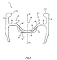
figure 10 schematically shows a cross section of an alternative embodiment of a rim in accordance with the present invention; -
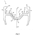
figure 11 schematically shows a cross section of a further alternative embodiment of a rim in accordance with the present invention. - With initial reference to
figures 1 and2 , a rim for a bicycle wheel in accordance with the present invention is indicated with 1. Such a rim is intended to be used in a tubeless wheel, preferably for a racing bicycle. - The
rim 1 comprises a body 5 having a substantially annular extension. The body 5 is configured to house and hold, in a final assembled configuration of the tyre, radially inner end edges 42 of a tyre 40 (figure 9 ), in the jargon known as beads. The body 5 is also configured to make the assembly steps of thetyre 40 easier, as shall be made clear hereafter. - The body 5 comprises a radially
outer portion 6a with which thetyre 40 is intended to be coupled and a radiallyinner portion 6b made in a single piece with the radiallyouter portion 6a. As shown infigure 1 , and in greater detail infigure 2 , the radiallyinner portion 6b is connected to the radiallyouter portion 6a through twoside walls 7, thus forming atubular structure 5a. The provision of the radiallyinner portion 6b in therim 1 of the present invention is particularly advantageous since it offers easy fixing areas for the spokes of the wheel (in the figures attached hereto to holes for such spokes are not illustrated). - The radially
outer portion 6a comprises anannular bottom wall 12, or upper bridge, and a pair ofannular side walls 10, or fins, extending substantially in the radial direction outwards from thebottom wall 12. Theside walls 10 in particular comprise a radiallyouter end portion 10a curved towards a plane of longitudinal symmetry π (illustrated infigure 2 ) of therim 1. - The
bottom wall 12 is totally without holes, with the exception of ahole 16 adapted to house aninflation valve 100 of the tyre 40 (figure 1 ,6 and9 ). -
Figure 9 shows how theside walls 10 cooperate with thetyre 40 and with thebottom wall 12 to form anairtight chamber 40a between them. Theannular side walls 10, and in particular the radiallyouter end portions 10a thereof, hold thetyre 40 in the final assembled configuration counteracting the thrust of the pressurised air on thetyre 40, thus generating an airtight coupling. - With reference to
figures 1 ,2 and6 , the body 5 has an identical geometry along the entire annular extension thereof, except in the area in which thehole 16 is provided, as shall be better described hereafter. In an alternative embodiment of therim 1 of the present invention, the geometry of the body 5 is identical along the entire annular extension of the rim, the only discontinuity being defined by thehole 16. - With reference to
figure 2 , thebottom wall 12 comprises, in a central portion thereof bridging the plane of longitudinal symmetry π of the rim, anannular recess 20. Thehole 16 is formed substantially at the centre of the recess 20 (figure 6 and7 ). - The
recess 20 defines a channel in which, in an initial assembly step of thetyre 40, at least one of thebeads 42 of the tyre is housed. - Again with reference to
figure 2 , thebottom wall 12 also comprises, on axially opposite sides with respect to therecess 20 and in a position adjacent to the twoannular side walls 10, two sideannular portions 24 substantially perpendicular to the plane of longitudinal symmetry π of therim 1 and, between theannular recess 20 and each of the sideannular portions 24, a projectingannular surface 22 having, in a transversal plane of the rim (like for example that offigure 2 ), a curved profile. - The projecting
annular surface 22 has a larger outer radial size than the outer radial size of theside portions 24 of thebottom wall 12 of therim 1. - As illustrated in
figure 9 , theside portions 24 of thebottom wall 12 and theside walls 10 of therim 1 define tworespective seats 18 for housing the twoopposite beads 42 of thetyre 40, where they are arranged in a final assembled configuration of the tyre. In the assembly step of thetyre 40, thebead 42 positioned in theannular recess 20 must pass the projectingsurface 22 to gain access to therespective seat 18. - Hereafter, with reference to
figure 3 , a detailed description of a first embodiment of the rim of the present invention shall be given. In particular, the surfaces that define theannular bottom wall 12 shall be defined in detail, conventionally considering as concave, convex or flat surfaces those surfaces of revolution about the rotation axis of the rim respectively with a concave, convex or straight generatrix line in a cross section of therim 1 made according to a radial plane passing through the aforementioned rotation axis, where the line is convex when the centre of curvature of such a line is on the side of the rotation axis of the rim whereas the line is concave when the centre of curvature is on the opposite side of the rotation axis of the rim. - Each
side portion 24 of thebottom wall 12 comprises a radially outer flat surface orientated substantially perpendicular to the plane of longitudinal symmetry π of the rim, whereas eachside wall 10 comprises an axially inner flat surface orientated substantially perpendicular to the rotation axis of the rim. The flat surfaces of theside portion 24 of thebottom wall 12 and of theside wall 10 are radiused through a respectivecurved surface 49. The aforementioned flat surfaces, together with the radiallyouter end portion 10a of theside walls 10, define theseats 18 for housing thebeads 42 of thetyre 40. - Each projecting
surface 22 is defined by aconvex surface 30 with a bending radius R1 (infigure 3 a part of the circle of radius R1 is indicated with a thin line). Such aconvex surface 30 is radiused to the flat surface of therespective side portion 24 of thebottom wall 12 through a concave joiningsurface 55 having a small bending radius. - The
recess 20 of thebottom wall 12 is defined by a plurality of surfaces. In particular, it comprises two convex side surfaces 28 having a bending radius R3 connected together through a concave connectingsurface 26 having a single bending radius R2 (infigure 3 part of the circles of radius R2 and R3 are indicated in a thin line). At one side of the recess 20 a radially innerconcave surface 26 and a radially outerconvex surface 28 can thus be identified. - The convex side surfaces 28 are directly radiused to the concave connecting
surface 26, being tangent to each other in a point P. - The convex side surfaces 28 are also directly radiused to the convex surfaces 30.
- The radius R3 is different to the radius R2. Preferably, the radius R3 is greater than the radius R2 and more preferably is equal to about twice the radius R2, with the approximation of a few tenths of a millimetre.
- The radius R2 is preferably between 2 mm and 5.5 mm, whereas the radius R3 is preferably about twice the radius R2.
- For example, in a particularly preferred embodiment of the rim illustrated in
figure 3 , the radius R2 is equal to about 4.2 mm, the radius R3 is equal to about 9 mm, the radius R1 is between 0.20 mm and 3 mm, preferably equal to about 0.5 mm, and the difference in level in the radial direction between theconvex surface 30 and the flat surface of therespective side portion 24 of thebottom wall 12 is equal to about 0.35 mm. -
Figure 4 shows a second embodiment of the rim of the present invention. - In such a
figure 4 , structural elements that are identical or equivalent from the functional point of view to those of the rim described above with reference tofigures 1-3 shall be indicated with the same reference numerals and they shall not be described any further. - The embodiment of
figure 4 differs from that offigure 3 in that the connectingsurface 26 is defined by surfaces having different bending radii. In particular, the connectingsurface 26 comprises, in acentral area 26b thereof bridging the axis of longitudinal symmetry π of the rim, a concave surface having a bending radius R'2 and, at theannular areas 26a thereof opposite thecentral area 26b, a concave surface having a bending radius R"2 different to R'2, preferably lower than R'2. - In this case, the convex side surfaces 28 are directly radiused to the concave surfaces of the
annular areas 26a, being tangent in a point P'. - In a particularly preferred embodiment of the rim illustrated in
figure 4 , the radius R'2 is equal to about 4.75 mm, the radius R''2 is equal to about 3.5 mm, the radius R3 is equal to about 7 mm, the radius R1 is equal to about 0.75 mm and the difference in level in the radial direction between theconvex surface 30 and the flat surface of therespective side portion 24 of thebottom wall 12 is equal to about 0.35 mm. The portion with radius R'2 extends in the axial direction along an arc of circumference having a cord C of a length equal to about 1.1 mm. -
Figure 5 shows a third embodiment of the rim of the present invention. - In such a
figure 5 , structural elements that are identical or equivalent from the functional point of view to those of the rim described above with reference tofigures 1-4 shall be indicated with the same reference numerals and they shall not be described any further. - The embodiment of
figure 5 differs from that offigure 4 in that the connectingsurface 26 is defined, at thecentral area 26b thereof bridging the axis of longitudinal symmetry π of the rim, by a flat surface or a concave surface having a very large bending radius, such as to define a substantially flat surface. Such a surface is radiused to the concave surfaces with bending radius R"2 of theannular areas 26a opposite thecentral area 26b. - In a particularly preferred embodiment of the rim illustrated in
figure 5 , the radius R"2 is equal to about 3.5 mm, the radius R3 is equal to about 7 mm, the radius R1 is equal to about 1.5 mm and the difference in level in the radial direction between theconvex surface 30 and the flat surface of therespective side portion 24 of thebottom wall 12 is equal to about 0.35 mm. The flat surface of thecentral area 26b extends in the axial direction for a portion L of a length equal to about 1.1 mm. - In a further embodiment (not illustrated) of the rim of the present invention, the connecting surface is flat (and therefore has an infinite bending radius). It is possible to foresee further embodiments in which the value of the bending radius R2 is anything from 2 to infinite.
- As already stated, in the preferred embodiment thereof, the
rim 1 has an identical geometry along its entire annular extension, except at thehole 16 and in an area proximal to such ahole 16. -
Figure 7 shows a cross section of therim 1 at thehole 16. In such an area of therim 1, thebottom wall 12 of therim 1 is shaped so as to form a seat 32 (figure 6 and7 ) for the head of the inflation valve of the tyre. Infigure 7 , structural elements that are identical or equivalent from the functional point of view to those of the rim described above with reference tofigures 1-6 shall be indicated with the same reference numerals and they shall not be described any further. - As shown in
figure 6 , at thehole 16 therecess 20 comprises two flat side surfaces 38 inclined by a predetermined angle α with respect to the plane of longitudinal symmetry of therim 1. The twoside surfaces 38 are connected by a substantially flat connectingsurface 36 or a concave surface having a very large bending radius R2, such as to define a substantially flat surface. The twoflat surfaces 38 are radiused with the connectingsurface 36 through a surface having a bending radius R4. The twoflat surfaces 38 define, with the connectingsurface 36, theseat 32 for housing the head of the inflation valve of the tyre. - In a radially outer position with respect to the
flat surfaces 38, i.e. on the opposite side of the connectingsurface 36 with respect to theflat surfaces 38, therecess 20 comprises two convex side surfaces 28 having a bending radius R3, in a way totally identical to what has been described above with reference tofigures 3-5 . Thebottom wall 12 also comprises, in an axially outer position with respect to therecess 20, two convex projecting surfaces 29 having a bending radius R1 and twoside portions 24 having flat surfaces, in a way totally identical to what has been described above with reference tofigures 3-5 . - Preferably, therefore, moving in the radial direction outwards from the radially outer end of the
flat surfaces 38, therim 1 of the present invention has the same geometry along the entire annular extension thereof, even at thehole 16 and at the area proximal to thehole 16, such a geometry being different only in the radially inner area of therecess 20 with respect to the convex side surfaces 28.Figure 8 , which is a section of therim 1 according to the radial plane P3 offigure 6 , shows the difference in geometry of thebottom wall 12, and in particular of theannular recess 20 formed in thebottom wall 12, between an area of the rim in which thehole 16 is not present and the area of the rim in which thehole 16 is formed. It should be noted how, at thehole 16, the base of therecess 20 is longer in the axial direction with respect to the areas of therim 1 that are not at thehole 16. - In particularly preferred embodiments of the rim of the present invention, at the
hole 16 the connectingsurface 36 has a bending radius R2 equal to about 35 mm and a length L in the axial direction equal to about 53 mm (thesurface 36 is thus substantially flat). In such embodiments, the angle of inclination α is equal to about 18°, the radius R4 is equal to about 1 mm, the radius R3 is equal to about 9 mm or alternatively 7 mm (depending on the size of therecess 20 in the areas of the rim distal from the hole 16), the radius R1 is equal to about 0.5 mm, or alternatively 0.75 mm or alternatively again 1.5 mm (depending on the size of therecess 20 in the areas of the rim distal from the hole 16) and the difference in level in the radial direction between theconvex surface 30 and the flat surface of therespective side portion 24 of thebottom wall 12 is equal to about 0.35 mm. -
Figures 10 and11 show alternative embodiments of a rim in accordance with the present invention. In such figures, structural elements that are identical or equivalent from the structural and functional point of view to those of the rim described above with reference tofigures 1-9 shall be indicated with the same reference numerals and they shall not be described any further. - Such a rim differs from the one described above and illustrated in
figures 1 to 9 for the different profile in cross section of thebottom wall 12 and for the arrangement on theupper bridge 12 of aband 50. - As illustrated, the
upper bridge 12 comprises, in addition to the inflation hole 16 (not visible infigure 10 ), further holes 17 for the assembly of spokes of the wheel. Theholes 17 are spaced apart on the bottom wall 12 - and from the hole 16 - in the circumferential direction. - The
band 50 is of the type described inUS2004/0095014 , but differs from it for its radially outer profile, with reference to a cross section of the band. In particular, theband 50 has an identical profile to that of the radially outer surface of therecess 20 of the rim described previously with reference tofigure 3 . - More specifically, the outer surface of the
band 50 comprises a concave radially inner surface 26' and two opposite convex radially outer surfaces 28' totally identical to thesurfaces figure 3 . Such surfaces are radiused together (in a single tangent point P') and to theconcave surfaces 30 of the projectingsurfaces 22 in a totally identical way to what has been described above with reference tofigure 3 . - Of course, the profile of the
band 50 can also be different from the one illustrated infigure 10 . For example, such a profile can be any of those described above with reference to the other embodiments that have or have not been illustrated, or it can be identical to that of the radially outer surface of theentire bottom wall 12 of the rim described previously with reference tofigure 3 . In this last case therefore, as illustrated infigure 11 , theband 50 also comprises two flat side portions 24', and two projectingsurfaces 22, having an outer profile totally identical to that of theside portions 24 and of the projectingsurfaces 22 of theupper bridge 12 of the rim described previously with reference tofigure 3 . - In any case, in the embodiments of the rim of the present invention in which the
band 50 is used, the profile of therecess 20 of the upper bridge 12' of the rim does not have particular innovative characteristics, the particular desired shape of therecess 20 indeed being obtained upon application of theband 50 onto the bottom wall 12'. - The
rim 1 of the present invention can be made from any material, for example metal, like an aluminium alloy. In combination with or as an alternative to the metallic material it is possible to use a structural composite material. - By composite material we mean a material consisting of at least two components including a polymeric matrix and a filler for example comprising structural fibres, granules or powders. The structural fibres are preferably selected from the group consisting of carbon fibres, glass fibres, aramid fibres, ceramic fibres, boron fibres and combinations thereof. Carbon fibres are particularly preferred. Preferably, the polymeric material is thermosetting and preferably comprises an epoxy resin. However, the possibility of using a thermoplastic material is not excluded.
- By structural composite materials we mean those materials that contain structural fibres with a length of over five millimetres. The arrangement of said structural fibres in the polymeric material can be a random arrangement of pieces or sheets of structural fibres, a substantially unidirectional ordered arrangement of fibres, a substantially bi-directional ordered arrangement of fibres or a combination of the above.
- In the case in which the
band 50 is used, such a band is preferably made from polymeric material, more preferably polypropylene, possibly reinforced with a polyester fabric. - Obviously, a man skilled in the art can bring numerous modifications and variants to the rim described above, in order to satisfy specific and contingent requirements, all of which are moreover comprised within the scope of protection of the present invention as defined by the following claims.
Claims (33)
- Rim (1) for a bicycle wheel comprising a body (5) with a substantially annular extension having a radially outer portion (6a) shaped for coupling with a tyre (40), said radially outer portion (6a) comprising an annular bottom wall (12) provided with a hole (16) for an inflation valve (100), said annular bottom wall (12) comprising a central annular recess (20) and two side annular portions (24) arranged on axially opposite sides with respect to said central annular recess (20), said recess (20) comprising, at least on one side thereof and at least in an area circumferentially distal from said hole (16), with reference to a cross section of the rim (1), a radially inner surface (26) and a radially outer surface (28), characterised in that said radially outer surface (28) has a bending radius (R3) different to that of said radially inner surface (26).
- Rim (1) according to claim 1, wherein said radially outer surface (28) is a curved surface.
- Rim (1) according to claim 2, wherein said radially outer surface (28) is a convex surface.
- Rim (1) according to any one of the previous claims, wherein said radially inner surface (26) comprises at least one portion of curved surface (26a, 26b).
- Rim (1) according to claim 4, wherein said curved surface (26a, 26b) is a concave surface.
- Rim (1) according to claim 5 when depending on claim 3, wherein said at least one portion of curved surface (26a) and said radially inner surface are radiused in a common tangent point (P).
- Rim (1) according to any one of claims 4 to 6, wherein the bending radius (R3) of said radially outer surface (28) is greater than that of said at least one curved portion (26a) of said radially inner surface (26).
- Rim (1) according to claim 7, wherein the bending radius (R3) of said radially outer surface (28) is equal to about twice that of said at least one curved portion (26a) of said radially inner surface (26).
- Rim (1) according to any one of the previous claims, wherein said annular bottom wall (12) comprises, between said radially outer surface (28) and at least one of said side annular portions (24), a projecting surface (22).
- Rim (1) according to claim 9, wherein said projecting surface (22) is defined by a curved surface (30).
- Rim (1) according to claim 10 when depending on claim 3, wherein said radially outer surface (28) and said projecting annular surface (22) are radiused in a common tangent point.
- Rim (1) according to any one of the previous claims, wherein said side annular portions (24) are substantially perpendicular to a plane of longitudinal symmetry (n) of said rim (1).
- Rim (1) according to any one of claims 4 to 12, wherein said radially inner surface (26) is entirely defined by a curved surface.
- Rim (1) according to claim 13, wherein said curved surface has a single bending radius (R2).
- Rim (1) according to claim 13, wherein said curved surface has a first bending radius (R'2) at a radially inner portion (26b) thereof and a second bending radius (R''2) at a radially outer portion (26a) thereof.
- Rim (1) according to claim 15, wherein said second bending radius (R''2) is smaller than said first bending radius (R'2).
- Rim (1) according to claim 15 or 16, wherein said at least one portion of curved surface is defined at said radially outer portion (26a).
- Rim (1) according to any one of claims 4 to 12, wherein said radially inner surface (26) is defined by a substantially flat surface portion (26b) and a curved surface portion (26a).
- Rim (1) according to claim 18, wherein said flat surface portion (26b) is axially more inner than said curved surface portion (26a).
- Rim (1) according to any one of the previous claims, wherein said central annular recess (20) has the same geometry along the entire annular extension of said rim (1).
- Rim (1) according to any one of claims 1 to 19, wherein said recess (20) comprises, at least on a side thereof and near to said hole (16), with reference to a cross section of the rim (1), an at least partially flat radially outer surface (38) and a substantially flat radially inner surface (36).
- Rim (1) according to claim 21, wherein said radially outer surface (38) comprises a flat surface portion adjacent to said radially inner surface (36) and a curved surface portion arranged on the opposite side to said radially inner surface (36) with respect to said flat surface portion.
- Rim (1) according to claim 22, wherein said curved surface portion has the same bending radius (R3) as that of the radially outer surface (28) of said recess (20) at said area distal from said hole (16).
- Rim (1) according to any one of the previous claims, wherein said rim (1) is a rim for a tubeless wheel.
- Rim (1) according to any one of the previous claims, wherein said rim (1) is made from metallic material.
- Rim (1) according to any one of claims 1 to 24, wherein said rim (1) is made from structural composite material.
- Bicycle wheel comprising a rim (1) according to any one of the previous claims.
- Bicycle comprising a wheel according to claim 27.
- Band (50) for sealing holes (17) for the assembly of spokes in a rim (1) for a tubeless bicycle wheel, characterised in that the band has, in a cross section thereof, an outer surface with an identical profile to at least that of the radially outer surface (28) of the central annular recess (20) formed in the annular bottom wall (12) of the rim (1) according to any one of claims 1 to 20.
- Band (50) according to claim 29, wherein said band (50) has an identical profile to that of the radially outer surface of the annular bottom wall (12) of said rim(1).
- Rim (1) for a tubeless bicycle wheel, comprising a body (5) with a substantially annular extension having a radially outer portion (6a) shaped for coupling with a tyre (40), said radially outer portion (6a) comprising an annular bottom wall (12) having a central annular recess (20) in which a first hole (16) for an inflation valve (40) and a plurality of second holes (17) for the assembly of respective spokes are formed, circumferentially spaced apart, said second holes (17) being sealed with a band (50) according to claim 29 or 30.
- Bicycle wheel comprising a rim (1) according to claim 31.
- Bicycle comprising a wheel according to claim 32.
Applications Claiming Priority (1)
| Application Number | Priority Date | Filing Date | Title |
|---|---|---|---|
| IT002232A ITMI20072232A1 (en) | 2007-11-26 | 2007-11-26 | RIM FOR BICYCLE WHEEL AND BICYCLE WHEEL INCLUDING SUCH RIM |
Publications (3)
| Publication Number | Publication Date |
|---|---|
| EP2062747A2 true EP2062747A2 (en) | 2009-05-27 |
| EP2062747A3 EP2062747A3 (en) | 2009-09-02 |
| EP2062747B1 EP2062747B1 (en) | 2011-01-19 |
Family
ID=40314760
Family Applications (1)
| Application Number | Title | Priority Date | Filing Date |
|---|---|---|---|
| EP08006139A Active EP2062747B1 (en) | 2007-11-26 | 2008-03-28 | Rim for a bicycle wheel and bicycle wheel comprising such a rim |
Country Status (9)
| Country | Link |
|---|---|
| US (2) | US8777328B2 (en) |
| EP (1) | EP2062747B1 (en) |
| JP (1) | JP5878274B2 (en) |
| CN (1) | CN101445019B (en) |
| AT (1) | ATE495910T1 (en) |
| AU (1) | AU2008243185A1 (en) |
| DE (1) | DE602008004613D1 (en) |
| IT (1) | ITMI20072232A1 (en) |
| TW (1) | TWI458651B (en) |
Cited By (3)
| Publication number | Priority date | Publication date | Assignee | Title |
|---|---|---|---|---|
| WO2011126463A1 (en) * | 2010-04-06 | 2011-10-13 | Jantsa Jant Sanayi Ve Ticaret A.S. | Locally-forged tubeless rim with reduced weight |
| ITUA20163283A1 (en) * | 2016-05-09 | 2017-11-09 | Provana Quality Center Srl | Vehicle wheel circle |
| EP3900946A1 (en) * | 2020-04-22 | 2021-10-27 | Campagnolo S.r.l. | Bicycle rim made of composite material with wings having reinforced structure |
Families Citing this family (32)
| Publication number | Priority date | Publication date | Assignee | Title |
|---|---|---|---|---|
| ATE390297T1 (en) | 2002-11-08 | 2008-04-15 | Campagnolo Srl | METHOD FOR PRODUCING A SPOKE WHEEL FOR BICYCLES |
| DE60320240T2 (en) | 2003-06-26 | 2009-06-25 | Campagnolo S.R.L. | Lightened bicycle rim and method of making such a rim |
| EP1506882B1 (en) | 2003-08-11 | 2008-07-09 | Campagnolo Srl | Composite bicycle rim and method for producing it |
| WO2007027927A1 (en) * | 2005-08-30 | 2007-03-08 | Wilderness Trail Bikes Licensing, Inc. | Bicycle wheel rim |
| ITMI20072231A1 (en) | 2007-11-26 | 2009-05-27 | Campagnolo Srl | RIM FOR BICYCLE WHEEL AND BICYCLE WHEEL INCLUDING SUCH RIM |
| ITMI20072232A1 (en) | 2007-11-26 | 2009-05-27 | Campagnolo Srl | RIM FOR BICYCLE WHEEL AND BICYCLE WHEEL INCLUDING SUCH RIM |
| EP2100751B1 (en) | 2008-03-14 | 2011-05-18 | Campagnolo S.r.l. | Rim made from composite material for a tubeless bicycle wheel and tubeless bicycle wheel comprising such a rim |
| CN102166918B (en) * | 2010-02-25 | 2013-02-06 | 亚猎士科技股份有限公司 | Bicycle wheel rim with reinforced structure of side wall step difference |
| US8490478B2 (en) | 2011-08-15 | 2013-07-23 | Lindsay Corporation | Tire pressure sensor mounting apparatus and method |
| US20130241269A1 (en) * | 2011-09-15 | 2013-09-19 | Peter Gilbert | Rim liner |
| US20130069421A1 (en) * | 2011-09-15 | 2013-03-21 | Peter Gilbert | Rim liner |
| CN102632764B (en) * | 2012-05-04 | 2015-06-03 | 广州市耐动信息科技有限公司 | Wheel rim for fixing inflation-free tire |
| US9216613B2 (en) * | 2012-07-12 | 2015-12-22 | Sram, Llc | Bicycle rim with brake track |
| KR20150090025A (en) | 2012-11-27 | 2015-08-05 | 엘지전자 주식회사 | Signal transceiving apparatus and signal transceiving method |
| FR3002880B1 (en) * | 2013-03-08 | 2015-05-29 | Mavic Sas | CYCLE WHEEL AND METHOD FOR MANUFACTURING THE SAME |
| FR3020013B1 (en) * | 2014-04-16 | 2017-12-01 | Michelin & Cie | ADAPTER FOR ROLLING ASSEMBLY AND ROLLING ASSEMBLY COMPRISING SAME |
| US9302532B2 (en) * | 2014-05-06 | 2016-04-05 | Mega Composite Technology Co., Ltd. | Spoked wheel for a bicycle |
| US20160263938A1 (en) * | 2015-03-12 | 2016-09-15 | Reynolds Cycling, Llc | Bicycle rim and wheel |
| JP6483324B2 (en) * | 2016-03-16 | 2019-03-20 | 本田技研工業株式会社 | Vehicle wheel |
| EP3504070A4 (en) * | 2016-08-29 | 2020-04-29 | Christian Feucht | RECESSED THROAT RIM AND RIM BAND TAPE APPARATUS AND SYSTEM |
| TWI696559B (en) * | 2017-03-30 | 2020-06-21 | 正新橡膠工業股份有限公司 | Bicycle tire structure without inner tube |
| US10647152B2 (en) * | 2017-05-08 | 2020-05-12 | Cheng Shin Rubber Industrial Co., Ltd. | Bicycle wheel rim for tubeless wheel |
| IT201700114693A1 (en) * | 2017-10-11 | 2019-04-11 | Campagnolo Srl | Bicycle wheel circle and wheel comprising it |
| CN107901699A (en) * | 2017-12-19 | 2018-04-13 | 中策橡胶集团有限公司 | A kind of resistance to knocking over without interior wheel rim |
| USD871293S1 (en) * | 2017-12-19 | 2019-12-31 | Janus Cycle Group, Inc. | Road tubeless bicycle rim |
| USD871294S1 (en) * | 2017-12-19 | 2019-12-31 | Janus Cycle Group, Inc. | Road tubeless bicycle rim |
| TWI701129B (en) * | 2019-06-21 | 2020-08-11 | 英屬維爾京群島商龍台工業股份有限公司 | Method of manufacturing a composite rim |
| US11660909B2 (en) * | 2019-12-11 | 2023-05-30 | Sram, Llc | Tire retaining feature for a bicycle rim |
| CN114670582B (en) * | 2020-12-24 | 2024-12-06 | 株式会社岛野 | Bicycle rim |
| IT202100017390A1 (en) * | 2021-07-01 | 2023-01-01 | F S A S R L | SEALANT RING BAND FOR WHEELS |
| DE102022121910A1 (en) * | 2022-08-30 | 2024-02-29 | Shimano Inc. | RIM FOR A HUMAN POWERED VEHICLE |
| TWI895824B (en) * | 2023-10-26 | 2025-09-01 | 鑫權工業有限公司 | Anti-tire rim structure |
Citations (3)
| Publication number | Priority date | Publication date | Assignee | Title |
|---|---|---|---|---|
| US6257676B1 (en) | 1997-07-25 | 2001-07-10 | Mavic S.A. | Bicycle rim provided for a tubeless assembly and bicycle wheel |
| US6568766B1 (en) | 2001-02-28 | 2003-05-27 | Shimano Inc. | Bicycle rim |
| US20040095014A1 (en) | 2002-11-20 | 2004-05-20 | Mavic S.A. | Base for a rim of a wheel and a rim having such a base |
Family Cites Families (142)
| Publication number | Priority date | Publication date | Assignee | Title |
|---|---|---|---|---|
| US1689649A (en) | 1928-10-30 | Kim with valve-stem jtastebtek | ||
| US401551A (en) | 1889-04-16 | Alexander gillies | ||
| US1402003A (en) | 1922-01-03 | miller | ||
| US395523A (en) | 1889-01-01 | Vehicle-wheel | ||
| BE398573A (en) * | ||||
| USRE15366E (en) | 1922-05-30 | Souri | ||
| US531914A (en) | 1895-01-01 | Samuel a | ||
| US452649A (en) | 1891-05-19 | Bicycle | ||
| US521385A (en) | 1894-06-12 | Felly for wheels | ||
| US677319A (en) | 1901-01-15 | 1901-06-25 | Emmett Mcconville | Vehicle-wheel. |
| US707335A (en) | 1902-01-06 | 1902-08-19 | Lowell H Kenyon | Locomotive driving-wheel. |
| US759124A (en) | 1902-12-01 | 1904-05-03 | William C Oswald | Vehicle-wheel. |
| US1286065A (en) | 1918-05-09 | 1918-11-26 | Thomas E Murray | Device for attaching the ends of wire wheel-spokes to metal rims. |
| US1393797A (en) | 1919-05-31 | 1921-10-18 | Bethlehem Steel Corp | Metal wheel |
| US1467588A (en) | 1919-12-12 | 1923-09-11 | Sydney I Prescott | Wheel rim |
| US1377173A (en) | 1920-04-20 | 1921-05-10 | William E Allen | Demountable-tire rim |
| US1484844A (en) | 1923-07-02 | 1924-02-26 | William B Olle | Metal bicycle-wheel rim |
| US1542630A (en) | 1924-07-10 | 1925-06-16 | Harry C Inman | Collapsible tire rim |
| US1667344A (en) | 1926-09-09 | 1928-04-24 | Chrysler Corp | Automobile wheel |
| US1684290A (en) | 1926-10-18 | 1928-09-11 | William J Starling | Balancing means for vehicle wheels |
| GB281229A (en) | 1926-11-26 | 1928-05-24 | Cie Applic Mecaniques | Rim for straight-sided pneumatic tyres with an improved security band or flap |
| US1847774A (en) | 1927-08-29 | 1932-03-01 | Kelsey Hayes Wheel Corp | Balanced disk wheel |
| FR657185A (en) | 1928-07-09 | 1929-05-17 | Light alloy hollow rim, for bicycles or other tubular velocipedes | |
| US1889577A (en) | 1928-08-04 | 1932-11-29 | Packard Motor Car Co | Motor vehicle |
| US1833879A (en) | 1928-08-15 | 1931-11-24 | Kelsay Hayes Wheel Corp | Balancing means for motor vehicle wheels |
| CH179922A (en) * | 1935-03-18 | 1935-09-30 | Aluminium Menziken & Gontensch | Vehicle wheel rim. |
| FR833629A (en) | 1937-06-28 | 1938-10-26 | Metal rim | |
| CH218795A (en) * | 1940-11-21 | 1941-12-31 | Caironi Walter | Flanged rim for bicycles. |
| US2840133A (en) | 1955-07-27 | 1958-06-24 | Goodrich Co B F | Tubeless tire and rim assembly |
| US2937905A (en) | 1955-11-29 | 1960-05-24 | Altenburger Karl | Spoke connection for tubeless tire rim |
| CH385646A (en) | 1960-04-05 | 1964-12-15 | Fichtel & Sachs Ag | Rim for tubeless tires |
| US3253862A (en) | 1964-06-08 | 1966-05-31 | Kelsey Hayes Co | Wheel and method of making the same |
| US3758931A (en) | 1971-12-29 | 1973-09-18 | Huffman Manuf Co | Wheel assembly method and apparatus |
| US4146274A (en) | 1974-03-25 | 1979-03-27 | Compagnie Generale Des Etablissements Michelin | Circumferentially reinforced wheel rims of moldable material |
| US4173992A (en) | 1974-03-25 | 1979-11-13 | Compagnie Generale Des Etablissements Michelin | Radially reinforced wheel rims of moldable material |
| US4040671A (en) | 1975-06-23 | 1977-08-09 | Hersh Lawrence K | Spoked wheel |
| US4181365A (en) | 1976-04-08 | 1980-01-01 | Honda Giken Kogyo Kabushiki Kaisha | Wheels for motorcycles |
| DE2640843A1 (en) | 1976-09-10 | 1978-03-16 | Kreidler Werke Gmbh | SINGLE TRACK TWO WHEELED VEHICLE |
| GB2009662B (en) * | 1977-12-09 | 1982-06-23 | Dunlop Ltd | Wheel rims |
| FR2474403A1 (en) | 1980-01-29 | 1981-07-31 | Ramond Louis | Tube cold-rolling roller mill support plate - has calibrating zone with alternating horizontal and inclined sections |
| US4376749A (en) | 1980-02-06 | 1983-03-15 | Motor Wheel Corporation | Fiber-reinforced composite wheel construction |
| US4527839A (en) | 1982-04-30 | 1985-07-09 | Honda Giken Kogyo Kabushiki Kaisha | Synthetic wheel formed from two halves |
| DE3238928A1 (en) | 1982-10-21 | 1984-04-26 | Continental Gummi-Werke Ag, 3000 Hannover | VALVE FOR TUBELESS TWO WHEEL BIKES |
| EP0133825B1 (en) | 1983-06-28 | 1987-09-09 | Elf Atochem S.A. | Flexible composite material and process for its production |
| SE439276B (en) | 1983-10-13 | 1985-06-10 | Monark Crescent Ab | SET AND DEVICE FOR POSSIBLE QUICK ATTENTION AND SUBSEQUENT FIXING OF SPREADS ASSEMBLED IN AN EXTRA WHEEL |
| JPS60137602U (en) * | 1984-02-25 | 1985-09-12 | 不二精工株式会社 | rim |
| US4702527A (en) | 1984-03-21 | 1987-10-27 | Honda Giken Kogyo Kabushiki Kaisha | Built-up wheel for vehicles |
| US4749235A (en) | 1984-11-21 | 1988-06-07 | The Budd Company | Composite wheel construction |
| JPS62227801A (en) | 1986-03-28 | 1987-10-06 | Sumitomo Rubber Ind Ltd | Wheel for motorcycle |
| IT1191589B (en) | 1986-06-25 | 1988-03-23 | Zampieri P | ANTI-SLIP DEVICE, PARTICULARLY FOR THE ADVANCE OF MOTOR VEHICLE WHEELS ON SNOW OR ICE |
| US4832414A (en) | 1987-03-09 | 1989-05-23 | Kelsey-Hayes Company | Filament wound wheel and a method for manufacturing the same |
| DK8289A (en) | 1988-01-12 | 1989-07-13 | Raychem Ltd | COMPOSITE |
| US4983430A (en) | 1989-03-21 | 1991-01-08 | Sargent Leigh R | Fiber reinforced composite product having a hollow interior |
| US5215137A (en) | 1989-11-06 | 1993-06-01 | Motor Wheel Corporation | Safety tire and take-apart wheel construction |
| US5073315A (en) | 1989-12-19 | 1991-12-17 | Bertelson Peter C | Methods for making fiber reinforced wheels and other structural moldings |
| US5279879A (en) | 1989-12-28 | 1994-01-18 | Tonen Corporation | Hybrid prepreg containing carbon fibers and at least one other reinforcing fiber in specific positions within the prepreg |
| JP3025849B2 (en) | 1991-01-30 | 2000-03-27 | 株式会社アペックス | Keystroke control method for automatic performance piano |
| US5271663A (en) | 1991-04-19 | 1993-12-21 | Superior Industries International, Inc. | Wheel and method for correcting rotational imbalance of tires |
| DE4127500C1 (en) | 1991-08-20 | 1992-10-01 | F.W. Broekelmann Aluminiumwerk Gmbh & Co., 4763 Ense, De | Bicycle spoked wheel with cavity rim - has nipple with axis-parallel multi-slit head held locked in outer wall, on insertion through cavity outer wall |
| DE4231539A1 (en) | 1991-12-07 | 1993-06-09 | Jochen 8221 Tacherting De Klieber | WHEEL FOR A VEHICLE |
| FR2693672B1 (en) | 1992-07-15 | 1994-11-04 | Mavic | Method of manufacturing a rim for cycle and rim produced with this method. |
| ES1024028Y (en) * | 1993-03-15 | 1994-04-01 | Nadal Aloy | SEALING DEVICE FOR RADIO WHEELS WITHOUT A CAMERA. |
| US5919044A (en) | 1993-09-27 | 1999-07-06 | Tru-Flex Post Systems, Inc. | Flexible post in a dental post and core system |
| US5534203A (en) | 1994-02-09 | 1996-07-09 | Radius Engineering, Inc. | Composite pole manufacturing process for varying non-circular cross-sections and curved center lines |
| DE69424047T2 (en) | 1994-03-24 | 2000-10-26 | Toray Industries, Inc. | CURVED TUBE, METHOD AND PRODUCTION APPARATUS |
| DE4425592A1 (en) | 1994-07-06 | 1996-01-11 | Hms Antriebssysteme Gmbh | Fibre reinforced plastic bicycle wheel, with special provision for rubber lock rim brakes |
| US5549360A (en) | 1994-08-15 | 1996-08-27 | Lipeles; Jay L. | Minimum weight wheel rim |
| US5540485A (en) | 1994-11-10 | 1996-07-30 | Enders; Mark L. | Composite bicycle wheel |
| FR2727355A1 (en) | 1994-11-30 | 1996-05-31 | Mavic Sa | METHOD FOR MANUFACTURING A RIM FOR A CYCLE AND RIM MADE WITH THIS METHOD |
| DE4444044C2 (en) | 1994-12-10 | 2001-11-08 | Josef Hasberg | Rim wheel for bicycles and the like |
| US5522630A (en) | 1995-03-30 | 1996-06-04 | James; Frank D. | Fishing tool for magnetic objects |
| DE69530126T2 (en) | 1995-12-04 | 2003-12-11 | Toray Industries | PRESSURE TANKS AND METHOD FOR THE PRODUCTION THEREOF |
| US6672352B2 (en) | 1995-12-26 | 2004-01-06 | Honda Giken Kogyo Kabushiki Kaisha | Tube-incorporated tire |
| ATE296851T1 (en) | 1996-02-21 | 2005-06-15 | Toray Industries | COMPOSITE THREAD AND FIBER REINFORCED COMPOSITE MATERIALS MADE THEREFROM |
| US5653510A (en) | 1996-02-21 | 1997-08-05 | Syncros Applied Technology Incorporated | Wheel rims |
| FR2750913B1 (en) | 1996-07-12 | 1998-10-09 | Mavic Sa | METHOD OF DRILLING A SPOKED RIM, RIM DRILLED ACCORDING TO THE METHOD, INSERT SUITABLE FOR EQUIPMENT ON THE RIM, AND WHEEL IN PARTICULAR FOR A CYCLE |
| RU2096188C1 (en) | 1996-07-31 | 1997-11-20 | Акционерное общество закрытого типа "Компания ЛЕМ" | Vehicle wheel |
| EP1354668B1 (en) | 1996-10-29 | 2008-05-21 | Victorinox | Multiple function tool |
| JPH10250309A (en) | 1997-03-17 | 1998-09-22 | R Thomasberg Paul | Tubeless tire and rim for bicycle |
| IT1292238B1 (en) | 1997-03-28 | 1999-01-29 | Campagnolo Srl | SPOKE FOR BICYCLE WHEEL AND WHEEL INCLUDING SUCH SPOKE. |
| US6086161A (en) | 1997-06-18 | 2000-07-11 | Nimble Bicycle Company | High performance broad application wheel |
| FR2765150B1 (en) | 1997-06-27 | 1999-08-27 | Mavic Sa | RIM FOR BICYCLE WHEEL |
| US6183047B1 (en) | 1997-07-18 | 2001-02-06 | Titan Wheel International, Inc. | Wheel rim top cover |
| FR2767285B1 (en) | 1997-08-13 | 1999-10-15 | Mavic Sa | RADIUS FOR CYCLE WHEEL, CYCLE WHEEL AND MANUFACTURING METHODS |
| US6024413A (en) | 1997-09-04 | 2000-02-15 | Spencer Technology, Inc. | Bicycle wheel and rim |
| ITTO980101A1 (en) | 1998-02-10 | 1999-08-10 | Campagnolo Srl | RACK FOR REAR BICYCLE WHEEL, SPOKED |
| US6593255B1 (en) | 1998-03-03 | 2003-07-15 | Ppg Industries Ohio, Inc. | Impregnated glass fiber strands and products including the same |
| JP3268356B2 (en) | 1998-08-31 | 2002-03-25 | 株式会社イノアックコーポレーション | Bicycle spoke rim wheels for tubeless tires |
| US6048035A (en) | 1998-11-23 | 2000-04-11 | Alex Machine Industrial Co., Ltd. | Bicycle wheel rim |
| US6196638B1 (en) | 1998-12-29 | 2001-03-06 | Shimano Inc. | Bicycle wheel |
| US6126243A (en) | 1998-12-29 | 2000-10-03 | Shimano, Inc. | Bicycle wheel |
| EP1169182B1 (en) | 1999-04-09 | 2003-07-16 | DT Swiss AG | Spoke nipple, especially for bicycles and the like |
| US6089672A (en) | 1999-05-27 | 2000-07-18 | Alex Machine Industrial Co., Ltd. | Bicycle wheel rim |
| FR2798622B1 (en) | 1999-09-17 | 2001-11-02 | Mavic Sa | BICYCLE RIM AND WHEEL COMPRISING SUCH A RIM |
| FR2801248B1 (en) | 1999-11-18 | 2002-02-08 | Mavic Sa | DEVICE FOR HANGING THE END OF A RADIUS TO A RIM OR HUB |
| DE60004312T2 (en) | 1999-12-09 | 2004-06-17 | Société de Technologie Michelin | Commercial vehicle wheel with a valve opening on the outside of the wheel disc |
| IT1319935B1 (en) | 2000-03-03 | 2003-11-12 | Campagnolo Srl | RIM FOR BICYCLE SPOKE WHEEL, PARTICULARLY FOR A TIRE WITHOUT AIR CHAMBER, AND WHEEL INCLUDING SUCH A RIM |
| US6318428B1 (en) | 2000-03-24 | 2001-11-20 | Tsai Jen Lo | Wheel rim and a seal member |
| FR2810582B1 (en) | 2000-06-27 | 2002-10-11 | Mavic Sa | DEVICE FOR HANGING A RADIUS AT THE RIM OF A BICYCLE WHEEL |
| IT1320582B1 (en) | 2000-08-03 | 2003-12-10 | Campagnolo Srl | CIRCLE FOR A BICYCLE WHEEL WITH TIRE WITHOUT AIR CHAMBER. |
| JP3524852B2 (en) | 2000-08-23 | 2004-05-10 | 株式会社キャットアイ | Magnet mounting structure |
| NL1016108C2 (en) | 2000-09-05 | 2002-03-07 | Prins Dokkum B V | Manufacture of composite wheel useful as truck wheel involves building up separate preforms, combining and compressing separate preforms into one whole, and impregnating compressed whole with synthetic resin |
| IT1320644B1 (en) | 2000-09-15 | 2003-12-10 | Campagnolo Srl | WHEEL HUB FOR BICYCLE. |
| US6347839B1 (en) | 2000-09-25 | 2002-02-19 | Polymeric Corporation The | Composite rim |
| US6536849B1 (en) | 2000-11-20 | 2003-03-25 | Shimano Inc. | Bicycle wheel |
| JP2002166702A (en) | 2000-12-01 | 2002-06-11 | Honda Motor Co Ltd | Balanced wheel and method of manufacturing the same |
| JP3479809B2 (en) | 2000-12-05 | 2003-12-15 | 本田技研工業株式会社 | Balanced wheel and method of manufacturing the same |
| US6425641B1 (en) | 2001-02-13 | 2002-07-30 | Jas. D. Easton, Inc. | Spoked cycle wheel |
| ITTO20010121A1 (en) | 2001-02-13 | 2002-08-13 | Campagnolo Srl | PROCEDURE FOR THE MANUFACTURE OF A BICYCLE WHEEL RIM, DEVICE FOR THE IMPLEMENTATION OF THE PROCEDURE, AND THE CIRCLE SO OBTAINED |
| TW481111U (en) | 2001-03-30 | 2002-03-21 | Alex Machine Ind Co Ltd | Wheel set for bicycle |
| US6582029B2 (en) | 2001-05-25 | 2003-06-24 | Shimano Inc. | Bicycle rim |
| JP4869523B2 (en) | 2001-07-18 | 2012-02-08 | ブリヂストンサイクル株式会社 | Internal pressure notification device for tires with tubes |
| JP2003094902A (en) | 2001-09-21 | 2003-04-03 | Nissan Motor Co Ltd | Tire wheel |
| TW505113U (en) | 2002-02-21 | 2002-10-01 | Ritchey Design Inc | Bicycle rim joint structure |
| JP2003260901A (en) | 2002-03-11 | 2003-09-16 | Araya Industrial Co Ltd | How to install bicycle spoke rim wheels and nipples for tubeless tires |
| US6938962B1 (en) | 2002-03-18 | 2005-09-06 | Raphael Schlanger | Vehicle wheel spoke termination |
| US6991300B2 (en) | 2002-07-31 | 2006-01-31 | James Colegrove | Optimum compaction low void composite bicycle wheel rim |
| ATE390297T1 (en) | 2002-11-08 | 2008-04-15 | Campagnolo Srl | METHOD FOR PRODUCING A SPOKE WHEEL FOR BICYCLES |
| EP1422078B2 (en) | 2002-11-21 | 2012-09-05 | Campagnolo S.r.l. | Spoked wheel for a bicycle |
| US7192098B2 (en) * | 2003-05-07 | 2007-03-20 | Shimano Inc. | Bicycle rim |
| US20040261512A1 (en) | 2003-05-21 | 2004-12-30 | Daly Paul Desmond | Wheel with plastic rim and integral sensor |
| DE60320240T2 (en) | 2003-06-26 | 2009-06-25 | Campagnolo S.R.L. | Lightened bicycle rim and method of making such a rim |
| US20050023883A1 (en) | 2003-08-01 | 2005-02-03 | Shimano Inc. | Bicycle rim |
| EP1506882B1 (en) | 2003-08-11 | 2008-07-09 | Campagnolo Srl | Composite bicycle rim and method for producing it |
| AT412628B (en) | 2003-10-14 | 2005-05-25 | Xentis Composite Produktions & | RIM |
| DE102004003873A1 (en) | 2004-01-26 | 2005-08-11 | Dt Swiss Ag | Bicycle wheel for tubeless tyres, comprises a wheel rim, a sealing device for openings in the rim, a liquid medium for sealing leaks, a valve for filling the tyre with air and another device for sealing the valve against the rim |
| DE602004012703D1 (en) * | 2004-01-27 | 2008-05-08 | Campagnolo Srl | Fixing system for spokes in a bicycle wheel |
| US20050210675A1 (en) | 2004-03-26 | 2005-09-29 | Price Chad N | Sealed tubeless tire bicycle wheel |
| CN2709212Y (en) | 2004-04-14 | 2005-07-13 | 亚猎士科技股份有限公司 | Sectional pull connecting type light wheel rim |
| CN2698620Y (en) * | 2004-06-06 | 2005-05-11 | 鞍山市振东轧钢有限公司 | Section steel for wheel rim |
| DE602004011339T2 (en) | 2004-08-31 | 2009-01-08 | Campagnolo S.R.L. | Rim for a bicycle spoked wheel, wheel and method of manufacture |
| US7334846B2 (en) | 2004-10-06 | 2008-02-26 | Koziatek Stanley F | Bicycle wheel rim |
| DE102004055892B4 (en) | 2004-11-19 | 2010-12-09 | Ktm-Sportmotorcycle Ag | Spoked wheel rim for tubeless tires |
| FR2881682B1 (en) | 2005-02-08 | 2007-04-27 | Salomon Sa | WHEEL RIM AND METHOD OF MANUFACTURE |
| US7431404B2 (en) * | 2005-08-05 | 2008-10-07 | Shimano Inc. | Bicycle having annular sealing member |
| WO2007027927A1 (en) * | 2005-08-30 | 2007-03-08 | Wilderness Trail Bikes Licensing, Inc. | Bicycle wheel rim |
| WO2009050411A1 (en) | 2007-10-17 | 2009-04-23 | Starco Dml Limited | A pressure relief valve |
| JP5125421B2 (en) | 2007-11-01 | 2013-01-23 | トヨタ紡織株式会社 | Vehicle seat structure |
| ITMI20072231A1 (en) | 2007-11-26 | 2009-05-27 | Campagnolo Srl | RIM FOR BICYCLE WHEEL AND BICYCLE WHEEL INCLUDING SUCH RIM |
| ITMI20072232A1 (en) | 2007-11-26 | 2009-05-27 | Campagnolo Srl | RIM FOR BICYCLE WHEEL AND BICYCLE WHEEL INCLUDING SUCH RIM |
| EP2100751B1 (en) | 2008-03-14 | 2011-05-18 | Campagnolo S.r.l. | Rim made from composite material for a tubeless bicycle wheel and tubeless bicycle wheel comprising such a rim |
| IT1392844B1 (en) * | 2009-01-14 | 2012-03-23 | Gianetti Ruote Spa | TUBELESS-TYPE SPOKE WHEEL FOR VEHICLES, IN PARTICULAR FOR MOTORCYCLES |
-
2007
- 2007-11-26 IT IT002232A patent/ITMI20072232A1/en unknown
-
2008
- 2008-03-28 EP EP08006139A patent/EP2062747B1/en active Active
- 2008-03-28 AT AT08006139T patent/ATE495910T1/en not_active IP Right Cessation
- 2008-03-28 DE DE602008004613T patent/DE602008004613D1/en active Active
- 2008-11-10 US US12/268,019 patent/US8777328B2/en active Active
- 2008-11-10 AU AU2008243185A patent/AU2008243185A1/en not_active Abandoned
- 2008-11-12 TW TW097143704A patent/TWI458651B/en not_active IP Right Cessation
- 2008-11-25 JP JP2008299358A patent/JP5878274B2/en not_active Expired - Fee Related
- 2008-11-26 CN CN2008101779722A patent/CN101445019B/en not_active Expired - Fee Related
-
2014
- 2014-06-19 US US14/308,924 patent/US20140292063A1/en not_active Abandoned
Patent Citations (3)
| Publication number | Priority date | Publication date | Assignee | Title |
|---|---|---|---|---|
| US6257676B1 (en) | 1997-07-25 | 2001-07-10 | Mavic S.A. | Bicycle rim provided for a tubeless assembly and bicycle wheel |
| US6568766B1 (en) | 2001-02-28 | 2003-05-27 | Shimano Inc. | Bicycle rim |
| US20040095014A1 (en) | 2002-11-20 | 2004-05-20 | Mavic S.A. | Base for a rim of a wheel and a rim having such a base |
Cited By (5)
| Publication number | Priority date | Publication date | Assignee | Title |
|---|---|---|---|---|
| WO2011126463A1 (en) * | 2010-04-06 | 2011-10-13 | Jantsa Jant Sanayi Ve Ticaret A.S. | Locally-forged tubeless rim with reduced weight |
| ITUA20163283A1 (en) * | 2016-05-09 | 2017-11-09 | Provana Quality Center Srl | Vehicle wheel circle |
| WO2017195099A1 (en) * | 2016-05-09 | 2017-11-16 | Provana Quality Center Srl | Wheel rim for agricultural vehicle |
| EP3900946A1 (en) * | 2020-04-22 | 2021-10-27 | Campagnolo S.r.l. | Bicycle rim made of composite material with wings having reinforced structure |
| US11745538B2 (en) | 2020-04-22 | 2023-09-05 | Campagnolo S.R.L. | Bicycle rim made of composite material with wings having reinforced structure |
Also Published As
| Publication number | Publication date |
|---|---|
| CN101445019B (en) | 2012-11-28 |
| DE602008004613D1 (en) | 2011-03-03 |
| EP2062747A3 (en) | 2009-09-02 |
| AU2008243185A1 (en) | 2009-06-11 |
| ATE495910T1 (en) | 2011-02-15 |
| US20140292063A1 (en) | 2014-10-02 |
| US8777328B2 (en) | 2014-07-15 |
| ITMI20072232A1 (en) | 2009-05-27 |
| TWI458651B (en) | 2014-11-01 |
| JP2009149290A (en) | 2009-07-09 |
| CN101445019A (en) | 2009-06-03 |
| TW200932577A (en) | 2009-08-01 |
| EP2062747B1 (en) | 2011-01-19 |
| JP5878274B2 (en) | 2016-03-08 |
| US20090134695A1 (en) | 2009-05-28 |
Similar Documents
| Publication | Publication Date | Title |
|---|---|---|
| EP2062747B1 (en) | Rim for a bicycle wheel and bicycle wheel comprising such a rim | |
| AU2008243198A1 (en) | Rim for a bicycle wheel and bicycle wheel comprising such a rim | |
| EP3495161B1 (en) | Insert for a rim of a spoked wheel for bicycle and respective spoked wheel for bicycle | |
| EP3902689B1 (en) | Flexible metallic web elements for non-pneumatic tire | |
| JP3701628B2 (en) | Bicycle rims and rim and tire assemblies | |
| EP3921183B2 (en) | Wheel rim structure for motor-vehicles | |
| EP1502768B1 (en) | Bicycle Rim | |
| US20140007998A1 (en) | Bicycle wheel | |
| EP3372421B1 (en) | Honeycomb rim-type wheel | |
| EP3902690B1 (en) | Non-pneumatic tire having reinforced support structure | |
| CN109649080B (en) | Bicycle rim and wheel comprising same | |
| US6843286B1 (en) | Tire/wheel assembly, run-flat support member and manufacturing method therefor | |
| US20240416677A1 (en) | Rim of a bicycle wheel and related bicycle wheel | |
| EP1782965A1 (en) | A wheel for vehicles and method for the manufacture thereof | |
| JP2007523794A (en) | Seal ring for automobile wheel | |
| RU2798383C2 (en) | Structure of a wheel rim for automobile vehicles | |
| US7188648B2 (en) | Tire/wheel assembly and run-flat support member | |
| WO2013154154A1 (en) | Inner multi-piece rim | |
| RU2061597C1 (en) | Rim of wheel for pneumatic tyre | |
| JP2009040101A (en) | Support and run-flat tire rim assembly |
Legal Events
| Date | Code | Title | Description |
|---|---|---|---|
| PUAI | Public reference made under article 153(3) epc to a published international application that has entered the european phase |
Free format text: ORIGINAL CODE: 0009012 |
|
| AK | Designated contracting states |
Kind code of ref document: A2 Designated state(s): AT BE BG CH CY CZ DE DK EE ES FI FR GB GR HR HU IE IS IT LI LT LU LV MC MT NL NO PL PT RO SE SI SK TR |
|
| AX | Request for extension of the european patent |
Extension state: AL BA MK RS |
|
| PUAL | Search report despatched |
Free format text: ORIGINAL CODE: 0009013 |
|
| AK | Designated contracting states |
Kind code of ref document: A3 Designated state(s): AT BE BG CH CY CZ DE DK EE ES FI FR GB GR HR HU IE IS IT LI LT LU LV MC MT NL NO PL PT RO SE SI SK TR |
|
| AX | Request for extension of the european patent |
Extension state: AL BA MK RS |
|
| RIC1 | Information provided on ipc code assigned before grant |
Ipc: B60B 21/02 20060101AFI20090324BHEP Ipc: B60B 21/10 20060101ALI20090724BHEP Ipc: B60B 21/12 20060101ALI20090724BHEP |
|
| 17P | Request for examination filed |
Effective date: 20091006 |
|
| 17Q | First examination report despatched |
Effective date: 20091105 |
|
| AKX | Designation fees paid |
Designated state(s): AT BE BG CH CY CZ DE DK EE ES FI FR GB GR HR HU IE IS IT LI LT LU LV MC MT NL NO PL PT RO SE SI SK TR |
|
| GRAP | Despatch of communication of intention to grant a patent |
Free format text: ORIGINAL CODE: EPIDOSNIGR1 |
|
| RIC1 | Information provided on ipc code assigned before grant |
Ipc: B60B 21/12 20060101ALI20100810BHEP Ipc: B60B 21/10 20060101ALI20100810BHEP Ipc: B60B 21/02 20060101AFI20100810BHEP |
|
| GRAS | Grant fee paid |
Free format text: ORIGINAL CODE: EPIDOSNIGR3 |
|
| GRAA | (expected) grant |
Free format text: ORIGINAL CODE: 0009210 |
|
| AK | Designated contracting states |
Kind code of ref document: B1 Designated state(s): AT BE BG CH CY CZ DE DK EE ES FI FR GB GR HR HU IE IS IT LI LT LU LV MC MT NL NO PL PT RO SE SI SK TR |
|
| REG | Reference to a national code |
Ref country code: GB Ref legal event code: FG4D |
|
| REG | Reference to a national code |
Ref country code: CH Ref legal event code: EP |
|
| REG | Reference to a national code |
Ref country code: IE Ref legal event code: FG4D |
|
| REF | Corresponds to: |
Ref document number: 602008004613 Country of ref document: DE Date of ref document: 20110303 Kind code of ref document: P |
|
| REG | Reference to a national code |
Ref country code: DE Ref legal event code: R096 Ref document number: 602008004613 Country of ref document: DE Effective date: 20110303 |
|
| REG | Reference to a national code |
Ref country code: NL Ref legal event code: T3 |
|
| REG | Reference to a national code |
Ref country code: CH Ref legal event code: NV Representative=s name: SCHMAUDER & PARTNER AG PATENT- UND MARKENANWAELTE |
|
| LTIE | Lt: invalidation of european patent or patent extension |
Effective date: 20110119 |
|
| PG25 | Lapsed in a contracting state [announced via postgrant information from national office to epo] |
Ref country code: IS Free format text: LAPSE BECAUSE OF FAILURE TO SUBMIT A TRANSLATION OF THE DESCRIPTION OR TO PAY THE FEE WITHIN THE PRESCRIBED TIME-LIMIT Effective date: 20110519 Ref country code: LV Free format text: LAPSE BECAUSE OF FAILURE TO SUBMIT A TRANSLATION OF THE DESCRIPTION OR TO PAY THE FEE WITHIN THE PRESCRIBED TIME-LIMIT Effective date: 20110119 Ref country code: GR Free format text: LAPSE BECAUSE OF FAILURE TO SUBMIT A TRANSLATION OF THE DESCRIPTION OR TO PAY THE FEE WITHIN THE PRESCRIBED TIME-LIMIT Effective date: 20110420 Ref country code: PT Free format text: LAPSE BECAUSE OF FAILURE TO SUBMIT A TRANSLATION OF THE DESCRIPTION OR TO PAY THE FEE WITHIN THE PRESCRIBED TIME-LIMIT Effective date: 20110519 Ref country code: SE Free format text: LAPSE BECAUSE OF FAILURE TO SUBMIT A TRANSLATION OF THE DESCRIPTION OR TO PAY THE FEE WITHIN THE PRESCRIBED TIME-LIMIT Effective date: 20110119 Ref country code: LT Free format text: LAPSE BECAUSE OF FAILURE TO SUBMIT A TRANSLATION OF THE DESCRIPTION OR TO PAY THE FEE WITHIN THE PRESCRIBED TIME-LIMIT Effective date: 20110119 Ref country code: HR Free format text: LAPSE BECAUSE OF FAILURE TO SUBMIT A TRANSLATION OF THE DESCRIPTION OR TO PAY THE FEE WITHIN THE PRESCRIBED TIME-LIMIT Effective date: 20110119 Ref country code: ES Free format text: LAPSE BECAUSE OF FAILURE TO SUBMIT A TRANSLATION OF THE DESCRIPTION OR TO PAY THE FEE WITHIN THE PRESCRIBED TIME-LIMIT Effective date: 20110430 Ref country code: NO Free format text: LAPSE BECAUSE OF FAILURE TO SUBMIT A TRANSLATION OF THE DESCRIPTION OR TO PAY THE FEE WITHIN THE PRESCRIBED TIME-LIMIT Effective date: 20110419 |
|
| PG25 | Lapsed in a contracting state [announced via postgrant information from national office to epo] |
Ref country code: BE Free format text: LAPSE BECAUSE OF FAILURE TO SUBMIT A TRANSLATION OF THE DESCRIPTION OR TO PAY THE FEE WITHIN THE PRESCRIBED TIME-LIMIT Effective date: 20110119 Ref country code: BG Free format text: LAPSE BECAUSE OF FAILURE TO SUBMIT A TRANSLATION OF THE DESCRIPTION OR TO PAY THE FEE WITHIN THE PRESCRIBED TIME-LIMIT Effective date: 20110419 Ref country code: CY Free format text: LAPSE BECAUSE OF FAILURE TO SUBMIT A TRANSLATION OF THE DESCRIPTION OR TO PAY THE FEE WITHIN THE PRESCRIBED TIME-LIMIT Effective date: 20110119 Ref country code: AT Free format text: LAPSE BECAUSE OF FAILURE TO SUBMIT A TRANSLATION OF THE DESCRIPTION OR TO PAY THE FEE WITHIN THE PRESCRIBED TIME-LIMIT Effective date: 20110119 Ref country code: SI Free format text: LAPSE BECAUSE OF FAILURE TO SUBMIT A TRANSLATION OF THE DESCRIPTION OR TO PAY THE FEE WITHIN THE PRESCRIBED TIME-LIMIT Effective date: 20110119 Ref country code: PL Free format text: LAPSE BECAUSE OF FAILURE TO SUBMIT A TRANSLATION OF THE DESCRIPTION OR TO PAY THE FEE WITHIN THE PRESCRIBED TIME-LIMIT Effective date: 20110119 Ref country code: FI Free format text: LAPSE BECAUSE OF FAILURE TO SUBMIT A TRANSLATION OF THE DESCRIPTION OR TO PAY THE FEE WITHIN THE PRESCRIBED TIME-LIMIT Effective date: 20110119 |
|
| PG25 | Lapsed in a contracting state [announced via postgrant information from national office to epo] |
Ref country code: EE Free format text: LAPSE BECAUSE OF FAILURE TO SUBMIT A TRANSLATION OF THE DESCRIPTION OR TO PAY THE FEE WITHIN THE PRESCRIBED TIME-LIMIT Effective date: 20110119 Ref country code: DK Free format text: LAPSE BECAUSE OF FAILURE TO SUBMIT A TRANSLATION OF THE DESCRIPTION OR TO PAY THE FEE WITHIN THE PRESCRIBED TIME-LIMIT Effective date: 20110119 Ref country code: MC Free format text: LAPSE BECAUSE OF NON-PAYMENT OF DUE FEES Effective date: 20110331 |
|
| PLBE | No opposition filed within time limit |
Free format text: ORIGINAL CODE: 0009261 |
|
| STAA | Information on the status of an ep patent application or granted ep patent |
Free format text: STATUS: NO OPPOSITION FILED WITHIN TIME LIMIT |
|
| PG25 | Lapsed in a contracting state [announced via postgrant information from national office to epo] |
Ref country code: SK Free format text: LAPSE BECAUSE OF FAILURE TO SUBMIT A TRANSLATION OF THE DESCRIPTION OR TO PAY THE FEE WITHIN THE PRESCRIBED TIME-LIMIT Effective date: 20110119 Ref country code: RO Free format text: LAPSE BECAUSE OF FAILURE TO SUBMIT A TRANSLATION OF THE DESCRIPTION OR TO PAY THE FEE WITHIN THE PRESCRIBED TIME-LIMIT Effective date: 20110119 |
|
| 26N | No opposition filed |
Effective date: 20111020 |
|
| PG25 | Lapsed in a contracting state [announced via postgrant information from national office to epo] |
Ref country code: MT Free format text: LAPSE BECAUSE OF FAILURE TO SUBMIT A TRANSLATION OF THE DESCRIPTION OR TO PAY THE FEE WITHIN THE PRESCRIBED TIME-LIMIT Effective date: 20110119 |
|
| REG | Reference to a national code |
Ref country code: IE Ref legal event code: MM4A |
|
| PG25 | Lapsed in a contracting state [announced via postgrant information from national office to epo] |
Ref country code: IE Free format text: LAPSE BECAUSE OF NON-PAYMENT OF DUE FEES Effective date: 20110328 |
|
| REG | Reference to a national code |
Ref country code: DE Ref legal event code: R097 Ref document number: 602008004613 Country of ref document: DE Effective date: 20111020 |
|
| REG | Reference to a national code |
Ref country code: AT Ref legal event code: MK05 Ref document number: 495910 Country of ref document: AT Kind code of ref document: T Effective date: 20110119 |
|
| GBPC | Gb: european patent ceased through non-payment of renewal fee |
Effective date: 20120328 |
|
| PG25 | Lapsed in a contracting state [announced via postgrant information from national office to epo] |
Ref country code: GB Free format text: LAPSE BECAUSE OF NON-PAYMENT OF DUE FEES Effective date: 20120328 |
|
| PG25 | Lapsed in a contracting state [announced via postgrant information from national office to epo] |
Ref country code: LU Free format text: LAPSE BECAUSE OF NON-PAYMENT OF DUE FEES Effective date: 20110328 |
|
| PG25 | Lapsed in a contracting state [announced via postgrant information from national office to epo] |
Ref country code: HU Free format text: LAPSE BECAUSE OF FAILURE TO SUBMIT A TRANSLATION OF THE DESCRIPTION OR TO PAY THE FEE WITHIN THE PRESCRIBED TIME-LIMIT Effective date: 20110119 |
|
| REG | Reference to a national code |
Ref country code: FR Ref legal event code: PLFP Year of fee payment: 9 |
|
| REG | Reference to a national code |
Ref country code: FR Ref legal event code: PLFP Year of fee payment: 10 |
|
| REG | Reference to a national code |
Ref country code: FR Ref legal event code: PLFP Year of fee payment: 11 |
|
| P01 | Opt-out of the competence of the unified patent court (upc) registered |
Effective date: 20230516 |
|
| PGFP | Annual fee paid to national office [announced via postgrant information from national office to epo] |
Ref country code: NL Payment date: 20240326 Year of fee payment: 17 |
|
| PGFP | Annual fee paid to national office [announced via postgrant information from national office to epo] |
Ref country code: DE Payment date: 20240327 Year of fee payment: 17 Ref country code: CZ Payment date: 20240306 Year of fee payment: 17 |
|
| PGFP | Annual fee paid to national office [announced via postgrant information from national office to epo] |
Ref country code: TR Payment date: 20240308 Year of fee payment: 17 Ref country code: IT Payment date: 20240321 Year of fee payment: 17 Ref country code: FR Payment date: 20240325 Year of fee payment: 17 |
|
| PGFP | Annual fee paid to national office [announced via postgrant information from national office to epo] |
Ref country code: CH Payment date: 20240402 Year of fee payment: 17 |
|
| REG | Reference to a national code |
Ref country code: DE Ref legal event code: R119 Ref document number: 602008004613 Country of ref document: DE |
|
| PG25 | Lapsed in a contracting state [announced via postgrant information from national office to epo] |
Ref country code: CZ Free format text: LAPSE BECAUSE OF NON-PAYMENT OF DUE FEES Effective date: 20250328 |
|
| REG | Reference to a national code |
Ref country code: CH Ref legal event code: H13 Free format text: ST27 STATUS EVENT CODE: U-0-0-H10-H13 (AS PROVIDED BY THE NATIONAL OFFICE) Effective date: 20251023 |
|
| REG | Reference to a national code |
Ref country code: NL Ref legal event code: MM Effective date: 20250401 |
|
| PG25 | Lapsed in a contracting state [announced via postgrant information from national office to epo] |
Ref country code: NL Free format text: LAPSE BECAUSE OF NON-PAYMENT OF DUE FEES Effective date: 20250401 |
|
| PG25 | Lapsed in a contracting state [announced via postgrant information from national office to epo] |
Ref country code: DE Free format text: LAPSE BECAUSE OF NON-PAYMENT OF DUE FEES Effective date: 20251001 |
|
| PG25 | Lapsed in a contracting state [announced via postgrant information from national office to epo] |
Ref country code: IT Free format text: LAPSE BECAUSE OF NON-PAYMENT OF DUE FEES Effective date: 20250328 Ref country code: FR Free format text: LAPSE BECAUSE OF NON-PAYMENT OF DUE FEES Effective date: 20250331 |
|
| PG25 | Lapsed in a contracting state [announced via postgrant information from national office to epo] |
Ref country code: CH Free format text: LAPSE BECAUSE OF NON-PAYMENT OF DUE FEES Effective date: 20250331 |