EP2100751B1 - Rim made from composite material for a tubeless bicycle wheel and tubeless bicycle wheel comprising such a rim - Google Patents
Rim made from composite material for a tubeless bicycle wheel and tubeless bicycle wheel comprising such a rim Download PDFInfo
- Publication number
- EP2100751B1 EP2100751B1 EP20080425161 EP08425161A EP2100751B1 EP 2100751 B1 EP2100751 B1 EP 2100751B1 EP 20080425161 EP20080425161 EP 20080425161 EP 08425161 A EP08425161 A EP 08425161A EP 2100751 B1 EP2100751 B1 EP 2100751B1
- Authority
- EP
- European Patent Office
- Prior art keywords
- rim
- radially outer
- layer
- outer portion
- hole
- Prior art date
- Legal status (The legal status is an assumption and is not a legal conclusion. Google has not performed a legal analysis and makes no representation as to the accuracy of the status listed.)
- Not-in-force
Links
Images


Classifications
-
- B—PERFORMING OPERATIONS; TRANSPORTING
- B60—VEHICLES IN GENERAL
- B60B—VEHICLE WHEELS; CASTORS; AXLES FOR WHEELS OR CASTORS; INCREASING WHEEL ADHESION
- B60B5/00—Wheels, spokes, disc bodies, rims, hubs, wholly or predominantly made of non-metallic material
- B60B5/02—Wheels, spokes, disc bodies, rims, hubs, wholly or predominantly made of non-metallic material made of synthetic material
-
- B—PERFORMING OPERATIONS; TRANSPORTING
- B60—VEHICLES IN GENERAL
- B60B—VEHICLE WHEELS; CASTORS; AXLES FOR WHEELS OR CASTORS; INCREASING WHEEL ADHESION
- B60B1/00—Spoked wheels; Spokes thereof
- B60B1/003—Spoked wheels; Spokes thereof specially adapted for bicycles
-
- B—PERFORMING OPERATIONS; TRANSPORTING
- B60—VEHICLES IN GENERAL
- B60B—VEHICLE WHEELS; CASTORS; AXLES FOR WHEELS OR CASTORS; INCREASING WHEEL ADHESION
- B60B21/00—Rims
- B60B21/02—Rims characterised by transverse section
- B60B21/04—Rims characterised by transverse section with substantially radial flanges
-
- B—PERFORMING OPERATIONS; TRANSPORTING
- B60—VEHICLES IN GENERAL
- B60B—VEHICLE WHEELS; CASTORS; AXLES FOR WHEELS OR CASTORS; INCREASING WHEEL ADHESION
- B60B21/00—Rims
- B60B21/12—Appurtenances, e.g. lining bands
-
- B—PERFORMING OPERATIONS; TRANSPORTING
- B60—VEHICLES IN GENERAL
- B60B—VEHICLE WHEELS; CASTORS; AXLES FOR WHEELS OR CASTORS; INCREASING WHEEL ADHESION
- B60B21/00—Rims
- B60B21/02—Rims characterised by transverse section
- B60B21/025—Rims characterised by transverse section the transverse section being hollow
-
- B—PERFORMING OPERATIONS; TRANSPORTING
- B60—VEHICLES IN GENERAL
- B60B—VEHICLE WHEELS; CASTORS; AXLES FOR WHEELS OR CASTORS; INCREASING WHEEL ADHESION
- B60B21/00—Rims
- B60B21/02—Rims characterised by transverse section
- B60B21/026—Rims characterised by transverse section the shape of rim well
-
- B—PERFORMING OPERATIONS; TRANSPORTING
- B60—VEHICLES IN GENERAL
- B60B—VEHICLE WHEELS; CASTORS; AXLES FOR WHEELS OR CASTORS; INCREASING WHEEL ADHESION
- B60B21/00—Rims
- B60B21/06—Rims characterised by means for attaching spokes, i.e. spoke seats
- B60B21/062—Rims characterised by means for attaching spokes, i.e. spoke seats for bicycles
-
- B—PERFORMING OPERATIONS; TRANSPORTING
- B60—VEHICLES IN GENERAL
- B60B—VEHICLE WHEELS; CASTORS; AXLES FOR WHEELS OR CASTORS; INCREASING WHEEL ADHESION
- B60B2900/00—Purpose of invention
- B60B2900/50—Improvement of
- B60B2900/511—Sealing
- B60B2900/5116—Sealing against air-loss
-
- Y—GENERAL TAGGING OF NEW TECHNOLOGICAL DEVELOPMENTS; GENERAL TAGGING OF CROSS-SECTIONAL TECHNOLOGIES SPANNING OVER SEVERAL SECTIONS OF THE IPC; TECHNICAL SUBJECTS COVERED BY FORMER USPC CROSS-REFERENCE ART COLLECTIONS [XRACs] AND DIGESTS
- Y10—TECHNICAL SUBJECTS COVERED BY FORMER USPC
- Y10T—TECHNICAL SUBJECTS COVERED BY FORMER US CLASSIFICATION
- Y10T29/00—Metal working
- Y10T29/49—Method of mechanical manufacture
- Y10T29/49481—Wheel making
- Y10T29/49492—Land wheel
- Y10T29/49524—Rim making
Definitions
- the present invention concerns a rim made from composite material for a tubeless bicycle wheel.
- the present invention also concerns a rim assembly and a tubeless wheel comprising such a rim, as well as a bicycle comprising such a wheel.
- a bicycle comprising such a wheel.
- the aforementioned bicycle is a racing bicycle.
- the present invention also concerns a method for manufacturing the aforementioned rim for a tubeless bicycle wheel.
- a bicycle wheel comprises a rim, on which a tyre is mounted, a hub and a plurality of spokes extending between the rim and the hub.
- the present patent application is referred to a so-called “tubeless" tyre, i.e. without an inner tube with annular extension, mounted between a radially outer portion of the rim and the tyre, which is inflated by introducing air through an inflation valve of such a tube.
- the inflated inner tube presses against the tyre, taking it into the operative condition of desired "inflation".
- the tyre is mounted airtight on a radially outer portion of the rim, so as to form an airtight annular chamber in which there is pressurised air introduced through an inflation valve associated with the rim at a suitable through hole formed in the radially outer portion of the rim. Air is put into such a chamber until the tyre has reached the operative condition of desired "inflation".
- Such rims are produced with a curing step in a suitable mould, maintaining a predetermined high temperature for a predetermined time. A through hole for the inflation valve is then made on the rim obtained from the mould.
- the inflation valve normally comprises a threaded shank and a head made from elastically deformable material at an end thereof, such a head being widened with respect to the size of the shank.
- the shank is inserted into the through hole of the rim so that a radially inner surface of the widened head goes into abutment on the radially outer portion of the rim, on the side thereof directed towards the tyre.
- the shank is also longer than the thickness of the rim, so that a nut, or a ring nut, can be screwed onto the shank, from its end opposed to that of the widened head, until it comes into abutment on a radially inner surface of the rim.
- the widened head made from elastically deformable material is compressed against a surface of the radially outer portion of the rim arranged around the inflation hole, so as to make an airtight closure of the inflation hole itself.
- a rim made from composite material for a tubeless bicycle wheel manufactured according to the aforementioned prior art has some drawbacks, the main one of which is linked to the fact that the tubeless wheels comprising the aforementioned rim are frequently subject to deflation problems, which often become apparent after only a few kilometres run by the cyclist.
- US 4527839 and JP 58 191601 disclose wheels for vehicles, particularly wheels for small-sized vehicles such as motorcycles and motored tricycles.
- Such wheels comprise respective rims made from fiber-reinforced resin.
- the preamble of claim 1 is based on the rims of US 4527839 .
- FR 2474403 discloses a rim for a bicycle wheel manufactured by moulding of plastic material.
- the technical problem at the basis of the present invention is to provide a rim made from composite material for a tubeless bicycle wheel that gives the tubeless wheel a high reliability, so as to overcome the drawbacks aforementioned with reference to the prior art, in a simple and effective manner.
- the present invention in a first aspect thereof, concerns a rim made from composite material as recited in claim 1 .
- composite material it is meant a material comprising at least two components, including a polymeric matrix and a filler comprising for example structural fibres.
- impermeable-to-air material any material without porosity, crackings or defects such as to allow air to pass, like for example a rubber.
- a tubeless wheel comprising the aforementioned rim ensures that a correct inflation of the tyre is maintained for an extremely long time. Indeed, the Applicant has surprisingly found that a crucial point for the deflation is not so much the hole but the portion of composite material around the hole. By making this portion impermeable-to-air the wheel remains inflated for much longer periods. The Applicant has discovered that this advantageous effect is due to the fact that the impermeable layer prevents air from coming out through possible through cracks or porosities (even very small sized ones) that can form, in a totally uncontrollable way, in the polymeric matrix of the composite material when the through hole itself is made, for example with a drill.
- the integral association of the aforementioned layer with the radially outer portion has the advantage of avoiding that, in the mounted tubeless wheel, the layer becomes crumpled up under the head of the inflation valve, for example due to a rotation thereof whilst it is locked on the rim. Moreover, by integrally associating the layer with the radially outer portion, the assembly operations of the tubeless wheel are made easier.
- the aforementioned first layer is at least partially arranged to coat the radially outer portion.
- the aforementioned layer is arranged on a radially outer surface of the radially outer portion that is intended, in a configuration with the wheel mounted, to face the tyre.
- the aforementioned layer is in contact with the head of the inflation valve, when it is mounted on the rim.
- the aforementioned rim comprises a second layer made from impermeable-to-air material and arranged, around the through hole, on a radially inner surface of the radially outer portion, opposite the radially outer surface. In this way, an even greater reliability is advantageously ensured.
- the aforementioned layer is arranged at least partially on the side walls that define the through hole.
- the through hole can be initially closed by elastic impermeable-to-air material, which is, subsequently, centrally perforated to make a smaller sized hole, intended for the inflation valve, with the advantage that crackings do not form on such an impermeable-to-air material.
- the aforementioned layer is at least partially arranged inside the thickness of the radially outer portion.
- the aforementioned impermeable-to-air material is elastically deformable.
- the aforementioned layer is advantageously able to perfectly couple with the elastically deformable material of the head of a valve inserted in the inflation hole, so as to make an airtight coupling, even in the case in which the two respective contact surfaces are not homogeneous.
- both the aforementioned layer and the head of the valve are elastically deformable, it is possible to make a mutual adaptation to the shape disuniformities in their contact area, for which reason an optimal airtight seal is obtained.
- the aforementioned elastically deformable material is an elastomer.
- the aforementioned layer is glued to the radially outer portion.
- the aforementioned layer is co-moulded with the radially outer portion.
- the aforementioned layer is advantageously intimately linked with the composite material of the rim, substantially penetrating into the possible cracks of the composite material itself.
- the aforementioned layer is a resin.
- such a resin incorporates particles of elastomer, which give the resin the elastic properties.
- the resin is applied by spraying onto the radially outer portion.
- the aforementioned layer of resin is advantageously intimately linked with the composite material of the rim, substantially penetrating into the possible cracks of the composite material itself.
- such a method of application of the aforementioned layer reduces the time to make the rim of the invention.
- the aforementioned layer is arranged on a radially outer surface of the radially outer portion that is intended, in a configuration with the wheel mounted, to face the tyre.
- the airtight seal of the coupling between layer and head of the inflation valve mounted on the rim is advantageously improved, especially in the case in which the resin incorporates particles of elastomer.
- the aforementioned elastomer with which the aforementioned layer is made or that is incorporated into the aforementioned resin is selected from the group consisting of nitrite elastomers, hydrogenated nitrite elastomers, ethylene propylene (EPM o EPDM), chloroprene elastomers, polyethylene chlorosulfate, polyacrylic elastomers, and fluorine elastomers.
- EPM o EPDM ethylene propylene
- chloroprene elastomers polyethylene chlorosulfate
- polyacrylic elastomers polyacrylic elastomers
- fluorine elastomers fluorine elastomers
- the aforementioned layer of the rim of the invention has a heat resistance above 85°C, and more preferably above 130°C. Even more preferably, such a layer has a heat resistance above 180°C.
- heat resistance of a material it is meant its temperature of glass transition which is known as “Tg”, above which the cured material softens and possibly chemically degrades losing the physical and mechanical properties.
- the aforementioned layer can withstand the high temperatures reached by the rim in the case in which it stays closed in a car under the sun or in the case in which, in use, the braking takes place by friction of the brakes on an outer edge of the rim.
- the aforementioned layer of the rim of the invention has a "Shore A" surface hardness, according to the standard DIN 53505, within the range 63 ⁇ 20%, including extremes.
- the inflation valve can be mounted on the rim by tightening the nut, or the ring nut, with a very high force, without fear of damaging or lacerating the layer of impermeable-to-air material.
- a housing seat is formed for a widened head of the inflation valve.
- the assembly of the tubeless wheel comprising the aforementioned rim is made easy and an optimal coupling is made between rim and inflation valve.
- the housing seat allows the inflation valve to be kept in a desired position during the insertion into the respective through hole of the rim, ensuring the correct assembly of the inflation valve on the rim, irrespective of the ability of the operator who performs the assembly.
- the layer in the case in which the aforementioned layer is arranged on a radially outer surface of the radially outer portion of the rim, the layer has a transversal extension, measured transversally with respect to the through hole, which is greater than the transversal extension of the area of said radially outer surface of said radially outer portion, arranged around the through hole and that is intended, in a configuration with the wheel mounted, to be in contact with a widened head of the inflation valve.
- the aforementioned layer is integrally associated along the entire circumferential extension of the radially outer portion.
- the tubeless wheel comprising the aforementioned rim made from composite material has an even greater reliability than that obtained in the previous cases, since air is prevented from coming out from possible further cracks of the radially outer portion of the rim, which are created in areas located far from the through hole.
- Such further cracks can be created due to the processings to which the rim made from composite material is subjected, in particular in the milling processing carried out on the rim extracted from the setting mould, such a processing being necessary to make, on the rim, extremely precise surfaces of coupling with the tyre to prevent air leaks, the setting mould being unable to ensure such a high precision.
- the present invention concerns a rim assembly comprising a rim of the type described above and an inflation valve crossing the through hole.
- a rim assembly separately or in combination has all of the structural and functional characteristics discussed above with reference to the aforementioned rim and therefore it has all of the aforementioned advantages.
- the inflation valve of the aforementioned rim assembly comprises a widened head in abutment on the radially outer portion of the rim.
- the impermeable-to-air material of the aforementioned layer is a resin arranged on a radially outer surface of the radially outer portion of the rim
- the inflation valve of the aforementioned rim assembly is glued to the radially outer portion of the rim through the resin itself.
- the resin also acts as an adhesive.
- the inflation valve of the rim assembly of the invention comprises a widened head made from elastomer, formed in one piece with the elastomer of the aforementioned layer. In this way, the perfect airtight seal is substantially ensured.
- the present invention concerns a tubeless bicycle wheel comprising a rim assembly of the type described above and a tyre mounted in an airtight manner on the radially outer portion of the rim.
- such a tubeless wheel separately or in combination has all of the structural and functional characteristics discussed above with reference to the aforementioned rim, or the aforementioned rim assembly, respectively, and therefore it has all of the aforementioned advantages.
- the present invention concerns a bicycle comprising a tubeless wheel of the type described above.
- such a bicycle separately or in combination has all of the structural and functional characteristics discussed above with reference to the aforementioned tubeless wheel and therefore it has all of the aforementioned advantages.
- the present invention concerns a method for manufacturing a rim made from composite material as recited in claim 26.
- a tubeless wheel comprising the rim made with such a method ensures excellent reliability, thanks to the provision of the aforementioned impermeable-to-air layer, for the same reasons outlined above in reference to the rim of the invention.
- the aforementioned layer can be a resin.
- the present invention also concerns a further method for manufacturing a rim made from composite material for a tubeless bicycle wheel, with which a rim that is extremely reliable is obtained, too. Such a further method is recited in claim 27 .
- the aforementioned first layer of the methods of the invention is elastically deformable.
- the respective integral-making step comprises a gluing of the aforementioned at least one layer to the radially outer portion.
- the respective integral-making step preferably comprises a co-moulding of the aforementioned at least one layer with the radially outer portion.
- the aforementioned layer is advantageously intimately linked with the composite material of the rim, substantially penetrating into the possible cracks of the composite material itself.
- the respective integral-making step preferably comprises a spray application of the aforementioned at least one layer onto the radially outer portion.
- the aforementioned layer is advantageously intimately linked with the composite material of the rim, substantially penetrating into the possible cracks of the composite material itself.
- the aforementioned integral-making step comprises a setting of the said substantially annular body and of the aforementioned at least one layer, maintaining a temperature of between 85°C and 250°C for a predetermined time.
- the aforementioned layer is advantageously intimately linked with the composite material of the rim, substantially penetrating into the possible cracks of the composite material itself.
- the aforementioned at least one layer is integral-made along the entire circumferential extension of the radially outer portion.
- a tubeless wheel comprising the rim made in this way ensures an even greater reliability than that obtained in the previous cases, since air is prevented from coming out from possible further cracks of the radially outer portion of the rim, which are created - as mentioned above - in areas located far from the through hole.
- a tubeless bicycle wheel in accordance with the present invention is shown. Such a wheel is globally indicated with 1.
- the tubeless wheel 1 comprises a rim 5 coupled with a tyre 10 so as to make an airtight coupling. Between the rim 5 and the tyre 10 a chamber is formed in which air is introduced through an inflation valve 15 associated with the rim.
- the rim 5 is made from composite material, comprising a filler incorporated in a polymeric matrix.
- the composite material of the rim 5 comprises structural fibres incorporated in a polymeric material.
- the structural fibres are selected from the group consisting of carbon fibres, glass fibres, aramid fibres, ceramic fibres, boron fibres and combinations thereof.
- the carbon fibres are particularly preferred.
- the arrangement of said structural fibres in the polymeric material can be a random arrangement of small pieces or leaflet of structural fibres, an ordered substantially unidirectional arrangement of fibres, an ordered substantially bidirectional arrangement of fibres, or a combination of the above.
- the polymeric material is thermo-setting and preferably comprises an epoxy resin.
- this does not exclude the possibility of using a thermoplastic.
- the rim 5 is connected to a hub 20 through spokes 21. Finally the wheel 1, and therefore the rim 5, has a rotation axis A whose direction defines the axial direction of the wheel (or of the rim), whereas radial direction of the wheel (or of the rim) is referred, in the present description and in the subsequent claims, to a direction perpendicular to the axis A and passing through the axis A itself.
- Figure 2 illustrates the rim 5 in greater detail, in particular it is visible a radially outer portion 38 of the rim 5, i.e. directed towards the tyre 10. It should be observed that on such a portion 38 there are no through openings, apart from a through hole 30 for the inflation valve 15. In this way, to ensure the airtight seal between the radially outer portion 38 of the rim 5 and the tyre 10, it is sufficient that the coupling between hole 30 and inflation valve 15 is airtight.
- the radially outer portion can also comprise holes for the anchorage of the spokes, which are closed through the application of plugs or a tape.
- the rim 5 comprises a body 6 with substantially annular extension.
- the body 6 is shaped to house and hold, in a final inflation configuration of the tyre 10, borders 11 of radially inner end of the tyre 10 ( figure 3 ), in the jargon known as beads.
- the body 6 comprises the radially outer portion 38 with which the tyre 10 is intended to be coupled and a radially inner portion 36 made in a single piece with the radially outer portion 38.
- the radially inner portion 36 and the radially outer portion 38 form a tubular structure of the rim 5, the radially inner portion 36 and the radially outer portion 38 being connected by two opposite annular side flanks 35.
- the provision of the radially inner portion 36 in the wheel 1 of the present invention is particularly advantageous since it offers easy anchorage areas for the spokes 21 of the wheel 1.
- the radially outer portion 38 includes an annular bottom wall 38a, or upper bridge, where the hole 30 is made, and a pair of annular side walls 40, or fins, extending substantially in radial direction outwards starting from the bottom wall 38a.
- the side walls 40 comprise in particular a radially outer end portion 40a curved towards the median plane of the rim 5, so as to be able to hold the radially inner end borders 11 of the tyre 10.
- figure 3 shows how the side walls 40 cooperate with the tyre 10 and with the bottom wall 38a to form among them a seal chamber 42 of the air.
- the bottom wall 38a comprises an annular central recess 44, which extends radially towards the inside of the rim 5 for the entire circumferential extension, the hole 30 being made in such a recess 44.
- the inflation valve 15 comprises a threaded shank 15a and a head 46 at an end thereof, such a head 46 being widened with respect to the size of the shank 15a.
- the shank 15a is inserted into the hole 30 and the head 46 is inserted into the recess 44.
- a bottom surface 48 of the head 46 stops in abutment on a bottom surface of the recess 44.
- the head 46 is made from elastically deformable material, for example an elastomer, or it is coated with such a material, so as to be able to adapt to the bottom surface of the recess 44 that is around the hole 30, thus making the desired airtight seal.
- a layer of impermeable-to-air material 55 preferably elastically deformable, different from the composite material used to make the other parts of the rim 5, is integrally associated.
- the elastically deformable material is preferably an elastomer selected from the group consisting of nitrite elastomers, hydrogenated nitrite elastomers, ethylene propylene (EPM or EPDM), chloroprene elastomers, polyethylene chlorosulfate, polyacrylic elastomers and fluorine elastomers.
- EPM or EPDM ethylene propylene
- chloroprene elastomers polyethylene chlorosulfate
- polyacrylic elastomers polyacrylic elastomers
- fluorine elastomers fluorine elastomers.
- non silicon-based rubbers are preferred, since silicon-based rubbers have low adherence, which - in tests carried out by the Applicant - proved insufficient to ensure the desired airtight seal.
- the selection of the elastomer is also made based upon its heat resistance, for which reason the elastomers with heat resistance of above 85°, more preferably above 130° and even more preferably above 180° are preferred, so as to withstand the polymerisation cycles to which the rim 5 made from composite material is subjected.
- the preferred elastically deformable material amongst those indicated above possesses a tensile strength - according to standards DIN 53504 - within the range 4.6 ⁇ 20% MPa including extremes, a percentage extensibility - according to standards DIN 53504 - within the range 368 ⁇ 20% including extremes, and a surface hardness "Shore A" - according to standards DIN 53505 - within the range 63 ⁇ 20% including extremes.
- the impermeable material 55 is a resin, for example applied by spraying.
- the resin can be the same one used as matrix of the composite material, or a different resin.
- Such a resin is used by itself or incorporates particles of elastomer, which is preferably selected from those indicated above.
- the impermeable material 55 is preferably arranged to form a layer above the bottom wall 38a, as shown in figure 3 .
- the layer of impermeable material 55 extends in axial direction up to the side walls 40, so that its dimensions are large enough and makes its installation easier.
- the axial extension can be smaller, until it involves just the area in contact with the head 46 of the valve, as illustrated in the further embodiment of the invention shown in figure 4 .
- Figure 5 illustrates the preferred extension of the layer of impermeable material 55 in circumferential direction, said direction being defined with respect to the axis A of the rim 5.
- the extension is greater than the bottom surface 48 of the head 46 of the valve 15.
- Figure 6 illustrates a further embodiment of the invention, in which the circumferential extension of the layer of impermeable material 55 is equal to the extension of the bottom surface 48 of the head 46 of the valve 15. However, it is not excluded the possibility of using a circumferential extension of the layer of impermeable material 55 that is lower than the extension of the bottom surface of the head of the valve.
- Figure 7 illustrates a further embodiment of the invention in which the bottom wall 38a comprises two layers of impermeable material 55, a first layer being arranged on the side of the bottom wall 38a directed radially outwards, a second layer being arranged on the side of the bottom wall 38a directed radially inwards.
- Figure 8 illustrates a further embodiment of the invention in which all the thickness of the bottom wall 38a, in the area that surrounds the hole 30, consists of impermeable material 55, i.e. the through hole 30 is in this case defined by cylindrical side walls entirely made from impermeable material 55.
- FIG 11 illustrates a further embodiment that makes it clear how the essential function of the impermeable layer 55 is to obstruct the cracks when they appear on surface.
- an impermeable layer 55 is used consisting of the same, and only, resin as the rim, applied on the entire radially outer surface of the rim. This is advantageous because normally the radially outer portion of the rim 38 is subjected to a finishing processing to ensure the perfect airtight coupling between rim and tyre. Such a processing, however, can generate crevices at any point of the rim, or put in evidence porosities of the material by removing the most outer layer.
- the coating layer being able to be applied with extreme precision after the processings of the rim have been carried out, for example by spraying, covers the crevices or porosities that appear on surface without altering the regularity of the coupling profile.
- the coating layer is obviously cured subsequently with respect to the manufacture of the rim.
- Figure 12 illustrates a further variant in which the impermeable layer 55 is made from elastic material and is inserted inside the thickness of the radially most outer portion of the rim. In this way, given that during the processing for making the hole 30 the elastic material does not crack, it interrupts and seals possible crevices that may form in the polymeric matrix.
- the layer - or the layers - of impermeable material 55 are in any case integral to the bottom wall 38a of the rim 5, for example through gluing, co-moulding with the remaining composite material of the rim 5, or spray application.
- Figure 9 shows a further embodiment of a rim according to the present invention, which is globally indicated with 105.
- the rim 105 differs from the rim 5 of figure 3 because its bottom wall 138a comprises a housing seat 60 for the head of the valve (not shown).
- the seat 60 is a recess in the bottom wall 138a, which extends radially towards the inside of the rim 105.
- such a recess substantially at the centre of which the hole 30 is formed, is intended to house the widened head, for example quadrangular-shaped, of the inflation valve so that a side surface of such a head is in abutment with a corresponding side surface of the recess, so as to make it easy to correctly locate the valve in the hole 30.
- Figure 10 which is a section of the rim 105 according to the radial plane having trace X - X of figure 9 , passing close to but not at the seat 60, shows in the foreground the transversal profile of the bottom wall 138a and in the background, with a broken line, the transversal profile of the aforementioned recess for the head of the valve (not shown).
- the layer of impermeable material 55 coats at least one bottom surface of the seat 60.
- the rim of composite material of the invention englobing the layer of impermeable material 55 is made by prearranging a plurality of overlapping layers of composite material, to form the bearing structure of the rim, and then arranging a further layer of impermeable material 55, elastic and/or resinous, at least in the area where the hole for the inflation valve shall be made.
- the whole of the aforementioned layers of the two materials is cured by subjecting it to a temperature of between 85°C and 250°C for a predetermined time.
- the curing temperature is greater than or equal to 120°C, and more preferably is greater than or equal to 130°C. Even more preferably, the curing temperature is greater than or equal to 170°C, whereas the best results are obtained with a curing temperature greater than or equal to 180°C.
- the layer of impermeable material 55 can be glued around the hole for the inflation valve, even if in this case the impermeable material 55 is linked less intimately with the composite material of the rim. In any case, the sealing effect of the cracks is ensured, since the points in which they appear on surface are covered.
- the coating layer 55 is applied to the rim after the curing and subsequently to the mechanical finishing processings, so as to subsequently seal the possible crevices that may have formed.
Abstract
Description
- The present invention concerns a rim made from composite material for a tubeless bicycle wheel.
- The present invention also concerns a rim assembly and a tubeless wheel comprising such a rim, as well as a bicycle comprising such a wheel. Preferably, the aforementioned bicycle is a racing bicycle.
- The present invention also concerns a method for manufacturing the aforementioned rim for a tubeless bicycle wheel.
- Typically, a bicycle wheel comprises a rim, on which a tyre is mounted, a hub and a plurality of spokes extending between the rim and the hub.
- In particular, the present patent application is referred to a so-called "tubeless" tyre, i.e. without an inner tube with annular extension, mounted between a radially outer portion of the rim and the tyre, which is inflated by introducing air through an inflation valve of such a tube. The inflated inner tube presses against the tyre, taking it into the operative condition of desired "inflation".
- In the tubeless wheel, on the contrary, the tyre is mounted airtight on a radially outer portion of the rim, so as to form an airtight annular chamber in which there is pressurised air introduced through an inflation valve associated with the rim at a suitable through hole formed in the radially outer portion of the rim. Air is put into such a chamber until the tyre has reached the operative condition of desired "inflation".
- In the prior art rims made from composite material, comprising carbon fibres incorporated in an epoxy matrix, are widely used.
- Such rims are produced with a curing step in a suitable mould, maintaining a predetermined high temperature for a predetermined time. A through hole for the inflation valve is then made on the rim obtained from the mould.
- The inflation valve normally comprises a threaded shank and a head made from elastically deformable material at an end thereof, such a head being widened with respect to the size of the shank. The shank is inserted into the through hole of the rim so that a radially inner surface of the widened head goes into abutment on the radially outer portion of the rim, on the side thereof directed towards the tyre.
- The shank is also longer than the thickness of the rim, so that a nut, or a ring nut, can be screwed onto the shank, from its end opposed to that of the widened head, until it comes into abutment on a radially inner surface of the rim. In particular, by further tightening the nut, or the ring nut, the widened head made from elastically deformable material is compressed against a surface of the radially outer portion of the rim arranged around the inflation hole, so as to make an airtight closure of the inflation hole itself.
- Although advantageous from the point of view of the simplicity of manufacture, the Applicant has found that a rim made from composite material for a tubeless bicycle wheel manufactured according to the aforementioned prior art has some drawbacks, the main one of which is linked to the fact that the tubeless wheels comprising the aforementioned rim are frequently subject to deflation problems, which often become apparent after only a few kilometres run by the cyclist.
-
US 4527839 andJP 58 191601 - Such wheels comprise respective rims made from fiber-reinforced resin. The preamble of claim 1 is based on the rims of
US 4527839 . - Furthermore,
FR 2474403 - The technical problem at the basis of the present invention is to provide a rim made from composite material for a tubeless bicycle wheel that gives the tubeless wheel a high reliability, so as to overcome the drawbacks aforementioned with reference to the prior art, in a simple and effective manner.
- Therefore the present invention, in a first aspect thereof, concerns a rim made from composite material as recited in claim 1.
- In the present patent application, by "composite material" it is meant a material comprising at least two components, including a polymeric matrix and a filler comprising for example structural fibres.
- In the present application by "impermeable-to-air material" it is also meant any material without porosity, crackings or defects such as to allow air to pass, like for example a rubber.
- The Applicant has surprisingly found that a tubeless wheel comprising the aforementioned rim ensures that a correct inflation of the tyre is maintained for an extremely long time. Indeed, the Applicant has surprisingly found that a crucial point for the deflation is not so much the hole but the portion of composite material around the hole. By making this portion impermeable-to-air the wheel remains inflated for much longer periods. The Applicant has discovered that this advantageous effect is due to the fact that the impermeable layer prevents air from coming out through possible through cracks or porosities (even very small sized ones) that can form, in a totally uncontrollable way, in the polymeric matrix of the composite material when the through hole itself is made, for example with a drill.
- It should be observed that in the layer of impermeable-to-air material, even if associated with the radially outer portion before the through hole is drilled, crackings do not form, for which reason the air - even in the presence of the aforementioned through cracks of the composite material - stops against this layer and does not come out.
- Furthermore, it should be observed that the integral association of the aforementioned layer with the radially outer portion has the advantage of avoiding that, in the mounted tubeless wheel, the layer becomes crumpled up under the head of the inflation valve, for example due to a rotation thereof whilst it is locked on the rim. Moreover, by integrally associating the layer with the radially outer portion, the assembly operations of the tubeless wheel are made easier.
- Preferably, the aforementioned first layer is at least partially arranged to coat the radially outer portion.
- More preferably, the aforementioned layer is arranged on a radially outer surface of the radially outer portion that is intended, in a configuration with the wheel mounted, to face the tyre. In this way, advantageously, the aforementioned layer is in contact with the head of the inflation valve, when it is mounted on the rim.
- Even more preferably, the aforementioned rim comprises a second layer made from impermeable-to-air material and arranged, around the through hole, on a radially inner surface of the radially outer portion, opposite the radially outer surface. In this way, an even greater reliability is advantageously ensured.
- In a further preferred embodiment of the rim of the invention, the aforementioned layer is arranged at least partially on the side walls that define the through hole. In this case, the through hole can be initially closed by elastic impermeable-to-air material, which is, subsequently, centrally perforated to make a smaller sized hole, intended for the inflation valve, with the advantage that crackings do not form on such an impermeable-to-air material.
- In a further preferred embodiment of the rim of the invention, the aforementioned layer is at least partially arranged inside the thickness of the radially outer portion.
- According to the invention, the aforementioned impermeable-to-air material is elastically deformable.
- In this way, the aforementioned layer is advantageously able to perfectly couple with the elastically deformable material of the head of a valve inserted in the inflation hole, so as to make an airtight coupling, even in the case in which the two respective contact surfaces are not homogeneous. Indeed, since both the aforementioned layer and the head of the valve are elastically deformable, it is possible to make a mutual adaptation to the shape disuniformities in their contact area, for which reason an optimal airtight seal is obtained.
- Preferably, the aforementioned elastically deformable material is an elastomer.
- In a first preferred embodiment of the rim of the invention, the aforementioned layer is glued to the radially outer portion.
- In a second preferred embodiment of the rim of the invention, the aforementioned layer is co-moulded with the radially outer portion. In this way, the aforementioned layer is advantageously intimately linked with the composite material of the rim, substantially penetrating into the possible cracks of the composite material itself. According to a further preferred embodiment of the rim of the invention, the aforementioned layer is a resin.
- Preferably, such a resin incorporates particles of elastomer, which give the resin the elastic properties.
- Preferably, the resin is applied by spraying onto the radially outer portion. In this way, especially if the rim on which such a resin is applied by spraying is subjected to a subsequent setting step, the aforementioned layer of resin is advantageously intimately linked with the composite material of the rim, substantially penetrating into the possible cracks of the composite material itself. Moreover, advantageously, such a method of application of the aforementioned layer reduces the time to make the rim of the invention.
- Even more preferably, the aforementioned layer is arranged on a radially outer surface of the radially outer portion that is intended, in a configuration with the wheel mounted, to face the tyre. In this way, the airtight seal of the coupling between layer and head of the inflation valve mounted on the rim is advantageously improved, especially in the case in which the resin incorporates particles of elastomer.
- Preferably, the aforementioned elastomer with which the aforementioned layer is made or that is incorporated into the aforementioned resin, is selected from the group consisting of nitrite elastomers, hydrogenated nitrite elastomers, ethylene propylene (EPM o EPDM), chloroprene elastomers, polyethylene chlorosulfate, polyacrylic elastomers, and fluorine elastomers. In the tests carried out by the Applicant, such elastomers proved particularly suitable for use in the rim of the invention.
- Preferably, the aforementioned layer of the rim of the invention has a heat resistance above 85°C, and more preferably above 130°C. Even more preferably, such a layer has a heat resistance above 180°C.
- In the present patent application, by "heat resistance" of a material it is meant its temperature of glass transition which is known as "Tg", above which the cured material softens and possibly chemically degrades losing the physical and mechanical properties.
- Advantageously, the aforementioned layer can withstand the high temperatures reached by the rim in the case in which it stays closed in a car under the sun or in the case in which, in use, the braking takes place by friction of the brakes on an outer edge of the rim.
- Preferably, the aforementioned layer of the rim of the invention has a "Shore A" surface hardness, according to the standard DIN 53505, within the range 63 ± 20%, including extremes.
- In this way, advantageously, the inflation valve can be mounted on the rim by tightening the nut, or the ring nut, with a very high force, without fear of damaging or lacerating the layer of impermeable-to-air material.
- In a preferred embodiment of the rim of the invention, on a radially outer surface of the radially outer portion, arranged around the through hole, a housing seat is formed for a widened head of the inflation valve.
- In this way, advantageously, the assembly of the tubeless wheel comprising the aforementioned rim is made easy and an optimal coupling is made between rim and inflation valve. Indeed, the housing seat allows the inflation valve to be kept in a desired position during the insertion into the respective through hole of the rim, ensuring the correct assembly of the inflation valve on the rim, irrespective of the ability of the operator who performs the assembly.
- In a preferred embodiment of the rim of the invention, in the case in which the aforementioned layer is arranged on a radially outer surface of the radially outer portion of the rim, the layer has a transversal extension, measured transversally with respect to the through hole, which is greater than the transversal extension of the area of said radially outer surface of said radially outer portion, arranged around the through hole and that is intended, in a configuration with the wheel mounted, to be in contact with a widened head of the inflation valve.
- In this way, the head of the valve mounted on the aforementioned rim completely rests on the aforementioned layer, thus improving the airtight seal between valve and rim at the through hole.
- In a further preferred embodiment of the rim of the invention, the aforementioned layer is integrally associated along the entire circumferential extension of the radially outer portion.
- The tubeless wheel comprising the aforementioned rim made from composite material has an even greater reliability than that obtained in the previous cases, since air is prevented from coming out from possible further cracks of the radially outer portion of the rim, which are created in areas located far from the through hole. Such further cracks can be created due to the processings to which the rim made from composite material is subjected, in particular in the milling processing carried out on the rim extracted from the setting mould, such a processing being necessary to make, on the rim, extremely precise surfaces of coupling with the tyre to prevent air leaks, the setting mould being unable to ensure such a high precision.
- In a second aspect thereof, the present invention concerns a rim assembly comprising a rim of the type described above and an inflation valve crossing the through hole. Preferably, such a rim assembly separately or in combination has all of the structural and functional characteristics discussed above with reference to the aforementioned rim and therefore it has all of the aforementioned advantages.
- Preferably, the inflation valve of the aforementioned rim assembly comprises a widened head in abutment on the radially outer portion of the rim.
- In an embodiment thereof, in the case in which the impermeable-to-air material of the aforementioned layer is a resin arranged on a radially outer surface of the radially outer portion of the rim, the inflation valve of the aforementioned rim assembly is glued to the radially outer portion of the rim through the resin itself. Advantageously, in this case, the resin also acts as an adhesive.
- In another embodiment thereof, in the case in which the impermeable-to-air material of the aforementioned layer is an elastomer, the inflation valve of the rim assembly of the invention comprises a widened head made from elastomer, formed in one piece with the elastomer of the aforementioned layer. In this way, the perfect airtight seal is substantially ensured.
- In a third aspect thereof, the present invention concerns a tubeless bicycle wheel comprising a rim assembly of the type described above and a tyre mounted in an airtight manner on the radially outer portion of the rim.
- Preferably, such a tubeless wheel separately or in combination has all of the structural and functional characteristics discussed above with reference to the aforementioned rim, or the aforementioned rim assembly, respectively, and therefore it has all of the aforementioned advantages.
- In a fourth aspect thereof, the present invention concerns a bicycle comprising a tubeless wheel of the type described above.
- Preferably, such a bicycle separately or in combination has all of the structural and functional characteristics discussed above with reference to the aforementioned tubeless wheel and therefore it has all of the aforementioned advantages.
- In a fifth aspect thereof, the present invention concerns a method for manufacturing a rim made from composite material as recited in claim 26.
- The Applicant has found that a tubeless wheel comprising the rim made with such a method ensures excellent reliability, thanks to the provision of the aforementioned impermeable-to-air layer, for the same reasons outlined above in reference to the rim of the invention.
- It should be observed that the aforementioned layer can be a resin.
- The present invention also concerns a further method for manufacturing a rim made from composite material for a tubeless bicycle wheel, with which a rim that is extremely reliable is obtained, too. Such a further method is recited in claim 27.
- According to the invention, the aforementioned first layer of the methods of the invention is elastically deformable.
- In a preferred embodiment of the methods of the invention, the respective integral-making step comprises a gluing of the aforementioned at least one layer to the radially outer portion.
- In a variant of the methods of the invention, the respective integral-making step preferably comprises a co-moulding of the aforementioned at least one layer with the radially outer portion. In this way, the aforementioned layer is advantageously intimately linked with the composite material of the rim, substantially penetrating into the possible cracks of the composite material itself.
- In a further variant of the methods of the invention, the respective integral-making step preferably comprises a spray application of the aforementioned at least one layer onto the radially outer portion. Also in this case, the aforementioned layer is advantageously intimately linked with the composite material of the rim, substantially penetrating into the possible cracks of the composite material itself.
- Preferably, the aforementioned integral-making step comprises a setting of the said substantially annular body and of the aforementioned at least one layer, maintaining a temperature of between 85°C and 250°C for a predetermined time.
- In this way, the aforementioned layer is advantageously intimately linked with the composite material of the rim, substantially penetrating into the possible cracks of the composite material itself.
- In a further variant of the methods of the invention, in the respective integral-making step, the aforementioned at least one layer is integral-made along the entire circumferential extension of the radially outer portion.
- A tubeless wheel comprising the rim made in this way ensures an even greater reliability than that obtained in the previous cases, since air is prevented from coming out from possible further cracks of the radially outer portion of the rim, which are created - as mentioned above - in areas located far from the through hole.
- Further characteristics and advantages of the present invention shall become clearer from the following detailed description of preferred embodiments thereof, made with reference to the attached drawings and given for indicating and not limiting purposes. In such drawings:
-
figure 1 schematically represents a perspective view of a tubeless bicycle wheel according to the present invention; -
figure 2 schematically represents a perspective view of the rim made from composite material of the wheel offigure 1 ; -
figure 3 schematically represents a section view of a portion of the wheel offigure 1 , taken according to a radial plane α offigure 1 , passing through the rotation axis of the wheel and through the longitudinal axis of the inflation valve of the wheel; -
figure 4 schematically represents a section view of a further embodiment of the tubeless wheel of the invention, said section being taken according to a plane analogous to the radial plane α offigure 1 ; -
figure 5 schematically represents a section of a portion of the wheel offigure 1 , taken according to the plane having trace V - V offigure 3 ; -
figures 6 ,7 and 8 schematically represent section views of further embodiments of portions of wheel of the invention, said sections being taken according to planes analogous to the plane having trace V - V offigure 3 ; -
figure 9 schematically represents a perspective view of a part of a further embodiment of the rim of the present invention, comprising a through hole for an inflation valve; -
figure 10 schematically represents a section view of the part of rim offigure 9 , taken according to the radial plane having trace X - X offigure 9 , passing through the rotation axis of the rim and passing close to the through hole for an inflation valve, outside a housing seat for a head of said inflation valve; -
figures 11 and 12 schematically represent section views of further embodiments of portions of wheel of the invention, said sections being taken according to planes analogous to the plane having trace V - V offigure 3 . - With initial reference to
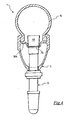
figure 1 , a tubeless bicycle wheel in accordance with the present invention is shown. Such a wheel is globally indicated with 1. - The tubeless wheel 1 comprises a
rim 5 coupled with atyre 10 so as to make an airtight coupling. Between therim 5 and the tyre 10 a chamber is formed in which air is introduced through aninflation valve 15 associated with the rim. - The
rim 5 is made from composite material, comprising a filler incorporated in a polymeric matrix. Typically, the composite material of therim 5 comprises structural fibres incorporated in a polymeric material. - Preferably, the structural fibres are selected from the group consisting of carbon fibres, glass fibres, aramid fibres, ceramic fibres, boron fibres and combinations thereof. The carbon fibres are particularly preferred.
- The arrangement of said structural fibres in the polymeric material can be a random arrangement of small pieces or leaflet of structural fibres, an ordered substantially unidirectional arrangement of fibres, an ordered substantially bidirectional arrangement of fibres, or a combination of the above.
- Preferably, the polymeric material is thermo-setting and preferably comprises an epoxy resin. However, this does not exclude the possibility of using a thermoplastic.
- The
rim 5 is connected to ahub 20 throughspokes 21. Finally the wheel 1, and therefore therim 5, has a rotation axis A whose direction defines the axial direction of the wheel (or of the rim), whereas radial direction of the wheel (or of the rim) is referred, in the present description and in the subsequent claims, to a direction perpendicular to the axis A and passing through the axis A itself. -
Figure 2 illustrates therim 5 in greater detail, in particular it is visible a radiallyouter portion 38 of therim 5, i.e. directed towards thetyre 10. It should be observed that on such aportion 38 there are no through openings, apart from a throughhole 30 for theinflation valve 15. In this way, to ensure the airtight seal between the radiallyouter portion 38 of therim 5 and thetyre 10, it is sufficient that the coupling betweenhole 30 andinflation valve 15 is airtight. Alternatively, the radially outer portion can also comprise holes for the anchorage of the spokes, which are closed through the application of plugs or a tape. - The
rim 5 comprises a body 6 with substantially annular extension. The body 6 is shaped to house and hold, in a final inflation configuration of thetyre 10, borders 11 of radially inner end of the tyre 10 (figure 3 ), in the jargon known as beads. - In particular, the body 6 comprises the radially
outer portion 38 with which thetyre 10 is intended to be coupled and a radiallyinner portion 36 made in a single piece with the radiallyouter portion 38. The radiallyinner portion 36 and the radiallyouter portion 38 form a tubular structure of therim 5, the radiallyinner portion 36 and the radiallyouter portion 38 being connected by two opposite annular side flanks 35. The provision of the radiallyinner portion 36 in the wheel 1 of the present invention is particularly advantageous since it offers easy anchorage areas for thespokes 21 of the wheel 1. - The radially
outer portion 38 includes anannular bottom wall 38a, or upper bridge, where thehole 30 is made, and a pair ofannular side walls 40, or fins, extending substantially in radial direction outwards starting from thebottom wall 38a. Theside walls 40 comprise in particular a radiallyouter end portion 40a curved towards the median plane of therim 5, so as to be able to hold the radially inner end borders 11 of thetyre 10. - In particular,
figure 3 shows how theside walls 40 cooperate with thetyre 10 and with thebottom wall 38a to form among them aseal chamber 42 of the air. Theside walls 40, and in particular the radiallyouter end portions 40a thereof, hold thetyre 10 in the final inflation configuration contrasting the thrust of the pressurised air on thetyre 10, thus generating the desired airtight coupling. - The
bottom wall 38a comprises an annularcentral recess 44, which extends radially towards the inside of therim 5 for the entire circumferential extension, thehole 30 being made in such arecess 44. - The
inflation valve 15 comprises a threaded shank 15a and ahead 46 at an end thereof, such ahead 46 being widened with respect to the size of the shank 15a. - When the
valve 15 is mounted on therim 5, the shank 15a is inserted into thehole 30 and thehead 46 is inserted into therecess 44. In particular, abottom surface 48 of thehead 46 stops in abutment on a bottom surface of therecess 44. - The
head 46 is made from elastically deformable material, for example an elastomer, or it is coated with such a material, so as to be able to adapt to the bottom surface of therecess 44 that is around thehole 30, thus making the desired airtight seal. - In accordance with a first embodiment of the present invention, on a area of
bottom wall 38a that surrounds the hole 30 a layer of impermeable-to-air material 55, preferably elastically deformable, different from the composite material used to make the other parts of therim 5, is integrally associated. - In particular the elastically deformable material is preferably an elastomer selected from the group consisting of nitrite elastomers, hydrogenated nitrite elastomers, ethylene propylene (EPM or EPDM), chloroprene elastomers, polyethylene chlorosulfate, polyacrylic elastomers and fluorine elastomers. In any case non silicon-based rubbers are preferred, since silicon-based rubbers have low adherence, which - in tests carried out by the Applicant - proved insufficient to ensure the desired airtight seal.
- The selection of the elastomer is also made based upon its heat resistance, for which reason the elastomers with heat resistance of above 85°, more preferably above 130° and even more preferably above 180° are preferred, so as to withstand the polymerisation cycles to which the
rim 5 made from composite material is subjected. - The preferred elastically deformable material amongst those indicated above possesses a tensile strength - according to standards DIN 53504 - within the range 4.6 ± 20% MPa including extremes, a percentage extensibility - according to standards DIN 53504 - within the range 368 ± 20% including extremes, and a surface hardness "Shore A" - according to standards DIN 53505 - within the range 63 ± 20% including extremes.
- Alternatively, the
impermeable material 55 is a resin, for example applied by spraying. The resin can be the same one used as matrix of the composite material, or a different resin. Such a resin is used by itself or incorporates particles of elastomer, which is preferably selected from those indicated above. - The
impermeable material 55 is preferably arranged to form a layer above thebottom wall 38a, as shown infigure 3 . In particular, the layer ofimpermeable material 55 extends in axial direction up to theside walls 40, so that its dimensions are large enough and makes its installation easier. - Alternatively, the axial extension can be smaller, until it involves just the area in contact with the
head 46 of the valve, as illustrated in the further embodiment of the invention shown infigure 4 . -
Figure 5 illustrates the preferred extension of the layer ofimpermeable material 55 in circumferential direction, said direction being defined with respect to the axis A of therim 5. In particular, it should be noted that the extension is greater than thebottom surface 48 of thehead 46 of thevalve 15. -
Figure 6 illustrates a further embodiment of the invention, in which the circumferential extension of the layer ofimpermeable material 55 is equal to the extension of thebottom surface 48 of thehead 46 of thevalve 15. However, it is not excluded the possibility of using a circumferential extension of the layer ofimpermeable material 55 that is lower than the extension of the bottom surface of the head of the valve. -
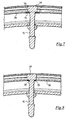
Figure 7 illustrates a further embodiment of the invention in which thebottom wall 38a comprises two layers ofimpermeable material 55, a first layer being arranged on the side of thebottom wall 38a directed radially outwards, a second layer being arranged on the side of thebottom wall 38a directed radially inwards. -
Figure 8 illustrates a further embodiment of the invention in which all the thickness of thebottom wall 38a, in the area that surrounds thehole 30, consists ofimpermeable material 55, i.e. the throughhole 30 is in this case defined by cylindrical side walls entirely made fromimpermeable material 55. -
Figure 11 illustrates a further embodiment that makes it clear how the essential function of theimpermeable layer 55 is to obstruct the cracks when they appear on surface. Infigure 11 animpermeable layer 55 is used consisting of the same, and only, resin as the rim, applied on the entire radially outer surface of the rim. This is advantageous because normally the radially outer portion of therim 38 is subjected to a finishing processing to ensure the perfect airtight coupling between rim and tyre. Such a processing, however, can generate crevices at any point of the rim, or put in evidence porosities of the material by removing the most outer layer. The coating layer, being able to be applied with extreme precision after the processings of the rim have been carried out, for example by spraying, covers the crevices or porosities that appear on surface without altering the regularity of the coupling profile. The coating layer is obviously cured subsequently with respect to the manufacture of the rim. -
Figure 12 illustrates a further variant in which theimpermeable layer 55 is made from elastic material and is inserted inside the thickness of the radially most outer portion of the rim. In this way, given that during the processing for making thehole 30 the elastic material does not crack, it interrupts and seals possible crevices that may form in the polymeric matrix. - Of course, the embodiments of the invention indicated above can be combined with one another, giving rise to further embodiments.
- It should be observed that the embodiments in which the layer - or the layers - of
impermeable material 55 are larger than thebottom surface 48 of thehead 46 of thevalve 15, both in axial and circumferential direction, are in any case preferred. In this way, air is prevented from coming out from cracks, crevices or similar that can form in the polymeric matrix during the making of thehole 30. - The layer - or the layers - of
impermeable material 55 are in any case integral to thebottom wall 38a of therim 5, for example through gluing, co-moulding with the remaining composite material of therim 5, or spray application. -
Figure 9 shows a further embodiment of a rim according to the present invention, which is globally indicated with 105. - In
figure 9 , to structural elements that are identical or equivalent from the functional point of view to those of therim 5 described above with reference tofigure 3 the same reference numerals shall be attributed and they shall not be described any further. - In particular, the
rim 105 differs from therim 5 offigure 3 because itsbottom wall 138a comprises ahousing seat 60 for the head of the valve (not shown). - In the illustrated example, the
seat 60 is a recess in thebottom wall 138a, which extends radially towards the inside of therim 105. - In particular, such a recess, substantially at the centre of which the
hole 30 is formed, is intended to house the widened head, for example quadrangular-shaped, of the inflation valve so that a side surface of such a head is in abutment with a corresponding side surface of the recess, so as to make it easy to correctly locate the valve in thehole 30. -
Figure 10 , which is a section of therim 105 according to the radial plane having trace X - X offigure 9 , passing close to but not at theseat 60, shows in the foreground the transversal profile of thebottom wall 138a and in the background, with a broken line, the transversal profile of the aforementioned recess for the head of the valve (not shown). - In this case the layer of
impermeable material 55 coats at least one bottom surface of theseat 60. - It should be observed that, in general, the rim of composite material of the invention englobing the layer of
impermeable material 55 is made by prearranging a plurality of overlapping layers of composite material, to form the bearing structure of the rim, and then arranging a further layer ofimpermeable material 55, elastic and/or resinous, at least in the area where the hole for the inflation valve shall be made. The whole of the aforementioned layers of the two materials is cured by subjecting it to a temperature of between 85°C and 250°C for a predetermined time. Preferably, the curing temperature is greater than or equal to 120°C, and more preferably is greater than or equal to 130°C. Even more preferably, the curing temperature is greater than or equal to 170°C, whereas the best results are obtained with a curing temperature greater than or equal to 180°C. - Alternatively, it should be observed that the layer of
impermeable material 55 can be glued around the hole for the inflation valve, even if in this case theimpermeable material 55 is linked less intimately with the composite material of the rim. In any case, the sealing effect of the cracks is ensured, since the points in which they appear on surface are covered. - According to an alternative method, the
coating layer 55 is applied to the rim after the curing and subsequently to the mechanical finishing processings, so as to subsequently seal the possible crevices that may have formed.
Claims (33)
- Rim (5, 105) made from composite material for a tubeless bicycle wheel (1) comprising a radially outer portion (38) shaped for the coupling with a tyre (10), said radially outer portion (38) comprising a through hole (30) for an inflation valve (15), wherein, around said hole (30), at least one first impermeable-to-air layer (55) is integrally associated with said radially outer portion (38), characterised in that said at least one first impermeable-to-air layer (55) is elastically deformable.
- Rim (5, 105) according to claim 1, wherein said at least one first layer (55) is at least partially arranged to coat the radially outer portion (38).
- Rim (5, 105) according to any one of the previous claims, wherein said at least one first layer (55) is arranged on a radially outer surface of said radially outer portion (38) that is intended, in a configuration with the wheel (1) mounted, to face the tyre (10).
- Rim (5, 105) according to claim 3, comprising a second layer (55) which is impermeable-to-air and arranged, around said hole (30), on a radially inner surface of said radially outer portion (38), opposite said radially outer surface.
- Rim (5, 105) according to claim 2, wherein said at least one first layer (55) is arranged at least partially on the side walls that define said through hole (30).
- Rim (5, 105) according to claim 1, wherein said at least one first layer (55) is at least partially arranged inside the thickness of the radially outer portion (38).
- Rim (5, 105) according to any one of the previous claims, wherein said impermeable-to-air layer/layers (55) is/are made from elastomer.
- Rim (5, 105) according to any one of the previous claims, wherein said at least one first layer (55) is glued to said radially outer portion (38).
- Rim (5, 105) according to any one of claims 1 to 7, wherein said at least one first layer (55) is co-moulded with said radially outer portion (38).
- Rim (5, 105) according to claim 1, wherein said at least one first layer (55) is a resin.
- Rim (5, 105) according to claim 10, wherein said resin incorporates particles of elastomer.
- Rim (5, 105) according to claim 10 or 11, wherein said at least one first layer (55) is applied by spraying onto said radially outer portion (38).
- Rim (5, 105) according to claim 12, wherein said at least one first layer (55) is arranged on a radially outer surface of said radially outer portion (38) that is intended, in a configuration with the wheel (1) mounted, to face the tyre (10).
- Rim (5, 105) according to claim 7 or 11, wherein said elastomer is selected from the group consisting of nitrite elastomers, hydrogenated nitrite elastomers, ethylene propylene (EPM or EPDM), chloroprene elastomers, polyethylene chlorosulfate, polyacrylic elastomers, and fluorine elastomers.
- Rim (5, 105) according to any one of the previous claims, wherein said at least one first layer (55) has a heat resistance above 85°C, preferably above 130°C, even more preferably above 180°C.
- Rim (5, 105) according to any one of the previous claims, wherein said at least one first layer (55) has a "Shore A" surface hardness, according to the standard DIN 53505, within the range 63 ± 20%, including extremes.
- Rim (105) according to any one of the previous claims, wherein on a radially outer surface of said radially outer portion (38), arranged around said through hole (30), a housing seat (60) is formed for a widened head (46) of said inflation valve (15).
- Rim (5, 105) according to claim 3 or 13, wherein said at least one first layer (55) has a transversal extension, measured transversally with respect to said through hole (30), which is greater than the transversal extension of the area of said radially outer surface of said radially outer portion (38), arranged around said through hole (30) and that is intended, in a configuration with the wheel (1) mounted, to be in contact with a widened head (46) of the inflation valve (15).
- Rim (5, 105) according to any one of the previous claims, wherein said at least one first layer (55) is integrally associated along the entire circumferential extension of said radially outer portion (38).
- Rim assembly comprising a rim (5, 105) according to any one of the previous claims and an inflation valve (15) crossing said through hole (30).
- Rim assembly according to claim 20, wherein said inflation valve (15) comprises a widened head (46) in abutment on said radially outer portion (38) of said rim (5, 105).
- Rim assembly according to claim 20 when dependent on claim 10, wherein said inflation valve (15) is glued to said radially outer portion (38) of said rim (5, 105) through said resin.
- Rim assembly according to claim 20 when dependent on claim 7, wherein said inflation valve (15) comprises a widened head (46) made from elastomer, formed in one piece with said at least one first layer (55).
- Tubeless bicycle wheel (1) comprising a rim assembly according to any one of claims 20 to 23, and a tyre (10) mounted in an airtight manner on said radially outer portion (38) of said rim (5, 105).
- Bicycle comprising a tubeless wheel (1) according to claim 24.
- Method for manufacturing a rim (5, 105) made from composite material for a tubeless bicycle wheel (1), comprising the steps of:A. forming a substantially annular body (6) of composite material, having a radially outer portion (38) shaped for the coupling with a tyre (10), prearranging fillers in a matrix of polymeric material;B. forming a through hole (30) in said radially outer portion (38);C. arranging at least one first impermeable-to-air layer (55) around said through hole (30), wherein said at least one first impermeable-to-air layer (55) is elastically deformable;D. making said at least one first layer (55) integral with said radially outer portion (38).
- Method for manufacturing a rim (5, 105) made from composite material for a tubeless bicycle wheel (1), comprising the steps of:A. forming a substantially annular body (6) of composite material, having a radially outer portion (38) shaped for the coupling with a tyre (10), prearranging fillers in a matrix of polymeric material;B. arranging at least one first impermeable-to-air layer (55) in an area of said radially outer portion (38), wherein said at least one first impermeable-to-air layer (55) is elastically deformable;C. forming, at said area, inside it, a hole (30) that crosses said radially outer portion (38) and said at least one first layer (55);D. making said at least one first layer (55) integral with said radially outer portion (38).
- Method according to any one of claims 26 to 27, wherein said integral-making step comprises a gluing of said at least one first layer (55) to said radially outer portion (38).
- Method according to any one of claims 26 to 27, wherein said integral-making step comprises a co-moulding of said at least one first layer (55) with said radially outer portion (38).
- Method according to claim 26, wherein said at least one layer (55) is a resin.
- Method according to any one of claims 26 to 27, wherein said integral-making step comprises a spray application of said at least one first layer (55) on said radially outer portion (38).
- Method according to any one of claims 26 to 31, wherein said integral-making step comprises a setting of said substantially annular body (6) and of said at least one first layer (55), maintaining a temperature of between 85°C and 250°C for a predetermined time.
- Method according to any one of claims 26 to 32, wherein, in said integral-making step, said at least one first layer (55) is integral-made along the entire circumferential extension of said radially outer portion (38).
Priority Applications (3)
| Application Number | Priority Date | Filing Date | Title |
|---|---|---|---|
| AT08425161T ATE509779T1 (en) | 2008-03-14 | 2008-03-14 | WHEEL RIM MADE OF COMPOSITE MATERIAL FOR A TUBELESS BICYCLE WHEEL AND A TUBELESS BICYCLE EQUIPPED WITH SUCH A WHEEL RIM |
| EP20080425161 EP2100751B1 (en) | 2008-03-14 | 2008-03-14 | Rim made from composite material for a tubeless bicycle wheel and tubeless bicycle wheel comprising such a rim |
| US12/401,936 US9079454B2 (en) | 2008-03-14 | 2009-03-11 | Rim made from composite material for a tubeless bicycle bicycle wheel and tubeless bicycle wheel comprising such a rim |
Applications Claiming Priority (1)
| Application Number | Priority Date | Filing Date | Title |
|---|---|---|---|
| EP20080425161 EP2100751B1 (en) | 2008-03-14 | 2008-03-14 | Rim made from composite material for a tubeless bicycle wheel and tubeless bicycle wheel comprising such a rim |
Publications (2)
| Publication Number | Publication Date |
|---|---|
| EP2100751A1 EP2100751A1 (en) | 2009-09-16 |
| EP2100751B1 true EP2100751B1 (en) | 2011-05-18 |
Family
ID=39600828
Family Applications (1)
| Application Number | Title | Priority Date | Filing Date |
|---|---|---|---|
| EP20080425161 Not-in-force EP2100751B1 (en) | 2008-03-14 | 2008-03-14 | Rim made from composite material for a tubeless bicycle wheel and tubeless bicycle wheel comprising such a rim |
Country Status (3)
| Country | Link |
|---|---|
| US (1) | US9079454B2 (en) |
| EP (1) | EP2100751B1 (en) |
| AT (1) | ATE509779T1 (en) |
Families Citing this family (19)
| Publication number | Priority date | Publication date | Assignee | Title |
|---|---|---|---|---|
| DE60225814T2 (en) | 2002-11-08 | 2009-04-30 | Campagnolo S.R.L. | Method of making a spoked wheel for bicycles |
| ES2305430T3 (en) | 2003-06-26 | 2008-11-01 | Campagnolo S.R.L. | ALLLED RIM FOR A BICYCLE WHEEL AND MANUFACTURING PROCEDURE OF SUCH RIM. |
| EP1506882B1 (en) | 2003-08-11 | 2008-07-09 | Campagnolo Srl | Composite bicycle rim and method for producing it |
| ITMI20072231A1 (en) | 2007-11-26 | 2009-05-27 | Campagnolo Srl | RIM FOR BICYCLE WHEEL AND BICYCLE WHEEL INCLUDING SUCH RIM |
| ITMI20072232A1 (en) | 2007-11-26 | 2009-05-27 | Campagnolo Srl | RIM FOR BICYCLE WHEEL AND BICYCLE WHEEL INCLUDING SUCH RIM |
| ATE509779T1 (en) | 2008-03-14 | 2011-06-15 | Campagnolo Srl | WHEEL RIM MADE OF COMPOSITE MATERIAL FOR A TUBELESS BICYCLE WHEEL AND A TUBELESS BICYCLE EQUIPPED WITH SUCH A WHEEL RIM |
| EP2643168B1 (en) | 2010-11-25 | 2020-08-12 | ENVE Composites, LLC | Optimum aerodynamic bicycle wheel |
| DE102010054657A1 (en) | 2010-12-15 | 2012-06-21 | Dt Swiss Ag | Rim made of fiber composite material for at least partially muscle-operated two-wheelers |
| US8490478B2 (en) | 2011-08-15 | 2013-07-23 | Lindsay Corporation | Tire pressure sensor mounting apparatus and method |
| US20130043717A1 (en) * | 2011-08-18 | 2013-02-21 | Sram, Llc | Bicycle rim with integral impact resistant structure and methods of making |
| US20130069421A1 (en) * | 2011-09-15 | 2013-03-21 | Peter Gilbert | Rim liner |
| US20130241269A1 (en) * | 2011-09-15 | 2013-09-19 | Peter Gilbert | Rim liner |
| US20140117745A1 (en) * | 2012-10-26 | 2014-05-01 | Trek Bicycle Corp. | Enhanced bicycle braking surfaces |
| US9321307B2 (en) | 2012-12-05 | 2016-04-26 | Shimano Inc. | Bicycle rim |
| FR3015359B1 (en) * | 2013-12-20 | 2016-01-01 | Michelin & Cie | FLEXIBLE RIM WITH FLOATING HOOKS |
| US9981500B2 (en) * | 2014-12-04 | 2018-05-29 | Enve Composites, Llc | Impact resistant rim |
| US9770944B2 (en) | 2015-02-27 | 2017-09-26 | ENVE Composities, LLC | Reflex rim for enhanced efficiency |
| JP1608343S (en) * | 2017-05-24 | 2018-07-09 | ||
| US11938764B2 (en) * | 2019-10-01 | 2024-03-26 | Sram, Llc | Tire inflation device |
Family Cites Families (161)
| Publication number | Priority date | Publication date | Assignee | Title |
|---|---|---|---|---|
| US521385A (en) | 1894-06-12 | Felly for wheels | ||
| US395523A (en) | 1889-01-01 | Vehicle-wheel | ||
| US401551A (en) | 1889-04-16 | Alexander gillies | ||
| US531914A (en) | 1895-01-01 | Samuel a | ||
| USRE15366E (en) | 1922-05-30 | Souri | ||
| US1689649A (en) | 1928-10-30 | Kim with valve-stem jtastebtek | ||
| US452649A (en) | 1891-05-19 | Bicycle | ||
| US1402003A (en) | 1922-01-03 | miller | ||
| US677319A (en) | 1901-01-15 | 1901-06-25 | Emmett Mcconville | Vehicle-wheel. |
| US707335A (en) | 1902-01-06 | 1902-08-19 | Lowell H Kenyon | Locomotive driving-wheel. |
| US759124A (en) | 1902-12-01 | 1904-05-03 | William C Oswald | Vehicle-wheel. |
| US1286065A (en) | 1918-05-09 | 1918-11-26 | Thomas E Murray | Device for attaching the ends of wire wheel-spokes to metal rims. |
| US1393797A (en) | 1919-05-31 | 1921-10-18 | Bethlehem Steel Corp | Metal wheel |
| US1467588A (en) | 1919-12-12 | 1923-09-11 | Sydney I Prescott | Wheel rim |
| US1377173A (en) | 1920-04-20 | 1921-05-10 | William E Allen | Demountable-tire rim |
| US1484844A (en) | 1923-07-02 | 1924-02-26 | William B Olle | Metal bicycle-wheel rim |
| US1542630A (en) | 1924-07-10 | 1925-06-16 | Harry C Inman | Collapsible tire rim |
| US1667344A (en) | 1926-09-09 | 1928-04-24 | Chrysler Corp | Automobile wheel |
| US1684290A (en) | 1926-10-18 | 1928-09-11 | William J Starling | Balancing means for vehicle wheels |
| GB281229A (en) | 1926-11-26 | 1928-05-24 | Cie Applic Mecaniques | Rim for straight-sided pneumatic tyres with an improved security band or flap |
| US1847774A (en) | 1927-08-29 | 1932-03-01 | Kelsey Hayes Wheel Corp | Balanced disk wheel |
| FR657185A (en) | 1928-07-09 | 1929-05-17 | Light alloy hollow rim, for bicycles or other tubular velocipedes | |
| US1889577A (en) | 1928-08-04 | 1932-11-29 | Packard Motor Car Co | Motor vehicle |
| US1833879A (en) | 1928-08-15 | 1931-11-24 | Kelsay Hayes Wheel Corp | Balancing means for motor vehicle wheels |
| CH179922A (en) | 1935-03-18 | 1935-09-30 | Aluminium Menziken & Gontensch | Vehicle wheel rim. |
| FR833629A (en) | 1937-06-28 | 1938-10-26 | Metal rim | |
| CH218795A (en) | 1940-11-21 | 1941-12-31 | Caironi Walter | Flanged rim for bicycles. |
| US2840133A (en) | 1955-07-27 | 1958-06-24 | Goodrich Co B F | Tubeless tire and rim assembly |
| US2937905A (en) | 1955-11-29 | 1960-05-24 | Altenburger Karl | Spoke connection for tubeless tire rim |
| CH385646A (en) | 1960-04-05 | 1964-12-15 | Fichtel & Sachs Ag | Rim for tubeless tires |
| US3253862A (en) | 1964-06-08 | 1966-05-31 | Kelsey Hayes Co | Wheel and method of making the same |
| US3758931A (en) | 1971-12-29 | 1973-09-18 | Huffman Manuf Co | Wheel assembly method and apparatus |
| JPS5246023B2 (en) | 1972-08-15 | 1977-11-21 | ||
| US4173992A (en) | 1974-03-25 | 1979-11-13 | Compagnie Generale Des Etablissements Michelin | Radially reinforced wheel rims of moldable material |
| US4146274A (en) | 1974-03-25 | 1979-03-27 | Compagnie Generale Des Etablissements Michelin | Circumferentially reinforced wheel rims of moldable material |
| US4040671A (en) | 1975-06-23 | 1977-08-09 | Hersh Lawrence K | Spoked wheel |
| US4017723A (en) | 1975-07-25 | 1977-04-12 | General Electric Company | Apparatus for controlling repetitive cutting cycles on a work piece being cut by a cutting tool of a lathe |
| US4181365A (en) | 1976-04-08 | 1980-01-01 | Honda Giken Kogyo Kabushiki Kaisha | Wheels for motorcycles |
| DE2640843A1 (en) | 1976-09-10 | 1978-03-16 | Kreidler Werke Gmbh | SINGLE TRACK TWO WHEELED VEHICLE |
| US4150854A (en) * | 1977-05-09 | 1979-04-24 | Tru-Spoke, Inc. | Wire wheel sealing system |
| GB2009662B (en) | 1977-12-09 | 1982-06-23 | Dunlop Ltd | Wheel rims |
| FR2426579A1 (en) * | 1978-05-25 | 1979-12-21 | Velox | Rim protection tape for spoked wheels - has double layer tape between rim and pneumatic tyre |
| FR2474403A1 (en) * | 1980-01-29 | 1981-07-31 | Ramond Louis | Tube cold-rolling roller mill support plate - has calibrating zone with alternating horizontal and inclined sections |
| US4286397A (en) | 1980-01-17 | 1981-09-01 | Snow Biz, Inc. | Ski boot walking accessory |
| US4376749A (en) | 1980-02-06 | 1983-03-15 | Motor Wheel Corporation | Fiber-reinforced composite wheel construction |
| US4410842A (en) | 1980-10-02 | 1983-10-18 | Lucas Industries Limited | Battery-powered electric vehicle d.c. motor control |
| US4527839A (en) * | 1982-04-30 | 1985-07-09 | Honda Giken Kogyo Kabushiki Kaisha | Synthetic wheel formed from two halves |
| JPS58191601A (en) * | 1982-04-30 | 1983-11-08 | Honda Motor Co Ltd | Wheel for vehicle |
| DE3238928A1 (en) | 1982-10-21 | 1984-04-26 | Continental Gummi-Werke Ag, 3000 Hannover | VALVE FOR TUBELESS TWO WHEEL BIKES |
| JPS59193702A (en) | 1983-04-18 | 1984-11-02 | Nippon Steel Corp | Method for rolling steel shape having hole in its web |
| DE3465922D1 (en) | 1983-06-28 | 1987-10-15 | Atochem | Flexible composite material and process for its production |
| JPS6012315A (en) | 1983-06-30 | 1985-01-22 | Yamaha Motor Co Ltd | Wire spork wheel |
| JPS6080902A (en) | 1983-10-11 | 1985-05-08 | Mitsubishi Rayon Co Ltd | Composite reinforced rim |
| SE439276B (en) | 1983-10-13 | 1985-06-10 | Monark Crescent Ab | SET AND DEVICE FOR POSSIBLE QUICK ATTENTION AND SUBSEQUENT FIXING OF SPREADS ASSEMBLED IN AN EXTRA WHEEL |
| JPS60137602U (en) | 1984-02-25 | 1985-09-12 | 不二精工株式会社 | rim |
| US4702527A (en) | 1984-03-21 | 1987-10-27 | Honda Giken Kogyo Kabushiki Kaisha | Built-up wheel for vehicles |
| US4804515A (en) | 1984-10-31 | 1989-02-14 | Westinghouse Electric Corp. | Distributed microprocessor based sensor signal processing system for a complex process |
| US4749235A (en) | 1984-11-21 | 1988-06-07 | The Budd Company | Composite wheel construction |
| JPH0234295B2 (en) | 1985-01-31 | 1990-08-02 | Showa Denko Kk | SEMENTOKANYOSEMENTOSURARIIMAKUKEISEISOCHI |
| JPS62275801A (en) | 1985-11-18 | 1987-11-30 | Toray Ind Inc | Rim for wheel and manufacture thereof |
| JP2557042B2 (en) | 1985-11-20 | 1996-11-27 | ソニー株式会社 | Program transfer device |
| IT1191589B (en) | 1986-06-25 | 1988-03-23 | Zampieri P | ANTI-SLIP DEVICE, PARTICULARLY FOR THE ADVANCE OF MOTOR VEHICLE WHEELS ON SNOW OR ICE |
| US4832414A (en) | 1987-03-09 | 1989-05-23 | Kelsey-Hayes Company | Filament wound wheel and a method for manufacturing the same |
| DK8289A (en) | 1988-01-12 | 1989-07-13 | Raychem Ltd | COMPOSITE |
| JPH01226401A (en) | 1988-03-07 | 1989-09-11 | Suzuki Motor Co Ltd | Spoke wheel for motor cycle |
| US4983430A (en) | 1989-03-21 | 1991-01-08 | Sargent Leigh R | Fiber reinforced composite product having a hollow interior |
| US5215137A (en) | 1989-11-06 | 1993-06-01 | Motor Wheel Corporation | Safety tire and take-apart wheel construction |
| US5073315A (en) | 1989-12-19 | 1991-12-17 | Bertelson Peter C | Methods for making fiber reinforced wheels and other structural moldings |
| US5279879A (en) | 1989-12-28 | 1994-01-18 | Tonen Corporation | Hybrid prepreg containing carbon fibers and at least one other reinforcing fiber in specific positions within the prepreg |
| JP3025849B2 (en) | 1991-01-30 | 2000-03-27 | 株式会社アペックス | Keystroke control method for automatic performance piano |
| JPH04306101A (en) | 1991-04-04 | 1992-10-28 | Toyota Motor Corp | Disc wheel for automobile |
| US5271663A (en) | 1991-04-19 | 1993-12-21 | Superior Industries International, Inc. | Wheel and method for correcting rotational imbalance of tires |
| DE4127500C1 (en) | 1991-08-20 | 1992-10-01 | F.W. Broekelmann Aluminiumwerk Gmbh & Co., 4763 Ense, De | Bicycle spoked wheel with cavity rim - has nipple with axis-parallel multi-slit head held locked in outer wall, on insertion through cavity outer wall |
| JPH07117423B2 (en) | 1991-09-30 | 1995-12-18 | 株式会社島津製作所 | Sensor output device |
| JPH07501022A (en) | 1991-11-15 | 1995-02-02 | クラインホーフ・クラウス | Spoke wheels, nipples for rims and spoke wheels and methods for building rims for spoke wheels |
| DE4231539A1 (en) | 1991-12-07 | 1993-06-09 | Jochen 8221 Tacherting De Klieber | WHEEL FOR A VEHICLE |
| FR2693672B1 (en) | 1992-07-15 | 1994-11-04 | Mavic | Method of manufacturing a rim for cycle and rim produced with this method. |
| ES1024028Y (en) | 1993-03-15 | 1994-04-01 | Nadal Aloy | SEALING DEVICE FOR RADIO WHEELS WITHOUT A CAMERA. |
| US5919044A (en) | 1993-09-27 | 1999-07-06 | Tru-Flex Post Systems, Inc. | Flexible post in a dental post and core system |
| US5534203A (en) | 1994-02-09 | 1996-07-09 | Radius Engineering, Inc. | Composite pole manufacturing process for varying non-circular cross-sections and curved center lines |
| CN1074714C (en) | 1994-03-24 | 2001-11-14 | 东丽株式会社 | Bent tube, Method of and apparatus for manufacturing same |
| DE4425592A1 (en) | 1994-07-06 | 1996-01-11 | Hms Antriebssysteme Gmbh | Fibre reinforced plastic bicycle wheel, with special provision for rubber lock rim brakes |
| US5549360A (en) | 1994-08-15 | 1996-08-27 | Lipeles; Jay L. | Minimum weight wheel rim |
| US5540485A (en) | 1994-11-10 | 1996-07-30 | Enders; Mark L. | Composite bicycle wheel |
| FR2727355A1 (en) | 1994-11-30 | 1996-05-31 | Mavic Sa | METHOD FOR MANUFACTURING A RIM FOR A CYCLE AND RIM MADE WITH THIS METHOD |
| DE4444044C2 (en) | 1994-12-10 | 2001-11-08 | Josef Hasberg | Rim wheel for bicycles and the like |
| WO1996018494A1 (en) | 1994-12-13 | 1996-06-20 | Dow-United Technologies Composite Products, Inc. | Shaped unidirectional fiber filler |
| US5522630A (en) | 1995-03-30 | 1996-06-04 | James; Frank D. | Fishing tool for magnetic objects |
| EP0810081B1 (en) | 1995-12-04 | 2003-03-26 | Toray Industries, Inc. | Pressure vessel and method of manufacturing same |
| US6672352B2 (en) | 1995-12-26 | 2004-01-06 | Honda Giken Kogyo Kabushiki Kaisha | Tube-incorporated tire |
| US5653510A (en) | 1996-02-21 | 1997-08-05 | Syncros Applied Technology Incorporated | Wheel rims |
| DE69733387T2 (en) | 1996-02-21 | 2006-04-27 | Toray Industries, Inc. | COMPOSITE AND FIBER-REINFORCED COMPOSITE MATERIALS MANUFACTURED THEREFROM |
| FR2750913B1 (en) | 1996-07-12 | 1998-10-09 | Mavic Sa | METHOD OF DRILLING A SPOKED RIM, RIM DRILLED ACCORDING TO THE METHOD, INSERT SUITABLE FOR EQUIPMENT ON THE RIM, AND WHEEL IN PARTICULAR FOR A CYCLE |
| RU2096188C1 (en) | 1996-07-31 | 1997-11-20 | Акционерное общество закрытого типа "Компания ЛЕМ" | Vehicle wheel |
| CN1159136C (en) | 1996-10-29 | 2004-07-28 | 维科托里诺克斯公司 | Multi-functional tool |
| JPH10250309A (en) * | 1997-03-17 | 1998-09-22 | R Thomasberg Paul | Tubeless tire and rim for bicycle |
| IT1292238B1 (en) | 1997-03-28 | 1999-01-29 | Campagnolo Srl | SPOKE FOR BICYCLE WHEEL AND WHEEL INCLUDING SUCH SPOKE. |
| US6086161A (en) | 1997-06-18 | 2000-07-11 | Nimble Bicycle Company | High performance broad application wheel |
| FR2765150B1 (en) | 1997-06-27 | 1999-08-27 | Mavic Sa | RIM FOR BICYCLE WHEEL |
| US6183047B1 (en) | 1997-07-18 | 2001-02-06 | Titan Wheel International, Inc. | Wheel rim top cover |
| FR2766419B1 (en) | 1997-07-25 | 1999-10-01 | Mavic Sa | BICYCLE RIM PROVIDED FOR TUBELESS MOUNTING AND BICYCLE WHEEL |
| FR2767285B1 (en) | 1997-08-13 | 1999-10-15 | Mavic Sa | RADIUS FOR CYCLE WHEEL, CYCLE WHEEL AND MANUFACTURING METHODS |
| US6024413A (en) | 1997-09-04 | 2000-02-15 | Spencer Technology, Inc. | Bicycle wheel and rim |
| ITTO980101A1 (en) | 1998-02-10 | 1999-08-10 | Campagnolo Srl | RACK FOR REAR BICYCLE WHEEL, SPOKED |
| US6593255B1 (en) | 1998-03-03 | 2003-07-15 | Ppg Industries Ohio, Inc. | Impregnated glass fiber strands and products including the same |
| JP3268356B2 (en) | 1998-08-31 | 2002-03-25 | 株式会社イノアックコーポレーション | Bicycle spoke rim wheels for tubeless tires |
| US6048035A (en) | 1998-11-23 | 2000-04-11 | Alex Machine Industrial Co., Ltd. | Bicycle wheel rim |
| US6126243A (en) | 1998-12-29 | 2000-10-03 | Shimano, Inc. | Bicycle wheel |
| US6196638B1 (en) | 1998-12-29 | 2001-03-06 | Shimano Inc. | Bicycle wheel |
| DE50002910D1 (en) | 1999-04-09 | 2003-08-21 | Dt Swiss Ag Biel | SPOKE NIPPLE, ESPECIALLY FOR BICYCLES AND THE LIKE |
| US6089672A (en) | 1999-05-27 | 2000-07-18 | Alex Machine Industrial Co., Ltd. | Bicycle wheel rim |
| US6019149A (en) * | 1999-09-08 | 2000-02-01 | Stringer; Raymond E. | Wheel seal and method |
| FR2798622B1 (en) | 1999-09-17 | 2001-11-02 | Mavic Sa | BICYCLE RIM AND WHEEL COMPRISING SUCH A RIM |
| FR2801248B1 (en) | 1999-11-18 | 2002-02-08 | Mavic Sa | DEVICE FOR HANGING THE END OF A RADIUS TO A RIM OR HUB |
| EP1106388B1 (en) | 1999-12-09 | 2003-08-06 | Société de Technologie Michelin | Industrial vehicle wheel with a valve, which opens outside the disk |
| IT1319935B1 (en) | 2000-03-03 | 2003-11-12 | Campagnolo Srl | RIM FOR BICYCLE SPOKE WHEEL, PARTICULARLY FOR A TIRE WITHOUT AIR CHAMBER, AND WHEEL INCLUDING SUCH A RIM |
| US6283557B1 (en) * | 2000-03-16 | 2001-09-04 | Shimano, Inc. | Bicycle rim with wear indicator |
| US6318428B1 (en) * | 2000-03-24 | 2001-11-20 | Tsai Jen Lo | Wheel rim and a seal member |
| FR2810582B1 (en) | 2000-06-27 | 2002-10-11 | Mavic Sa | DEVICE FOR HANGING A RADIUS AT THE RIM OF A BICYCLE WHEEL |
| IT1320582B1 (en) | 2000-08-03 | 2003-12-10 | Campagnolo Srl | CIRCLE FOR A BICYCLE WHEEL WITH TIRE WITHOUT AIR CHAMBER. |
| JP3524852B2 (en) | 2000-08-23 | 2004-05-10 | 株式会社キャットアイ | Magnet mounting structure |
| NL1016108C2 (en) | 2000-09-05 | 2002-03-07 | Prins Dokkum B V | Manufacture of composite wheel useful as truck wheel involves building up separate preforms, combining and compressing separate preforms into one whole, and impregnating compressed whole with synthetic resin |
| IT1320644B1 (en) | 2000-09-15 | 2003-12-10 | Campagnolo Srl | WHEEL HUB FOR BICYCLE. |
| US6347839B1 (en) | 2000-09-25 | 2002-02-19 | Polymeric Corporation The | Composite rim |
| AU2002212300A1 (en) | 2000-10-17 | 2002-04-29 | Vuelta International S.P.A. | Rim for mounting tubeless tires, particularly for bicycles, motorcycles and mopeds |
| FR2816548B1 (en) | 2000-11-14 | 2003-02-28 | Salomon Sa | PROCESS FOR THE MANUFACTURE OF A BICYCLE RIM PROVIDED FOR MOUNTING WITHOUT AN AIR TUBE AND RIM OBTAINED BY IMPLEMENTING THE PROCESS |
| US6536849B1 (en) | 2000-11-20 | 2003-03-25 | Shimano Inc. | Bicycle wheel |
| JP2002166702A (en) | 2000-12-01 | 2002-06-11 | Honda Motor Co Ltd | Balance adjusted wheel and method of manufacturing the same |
| JP3479809B2 (en) | 2000-12-05 | 2003-12-15 | 本田技研工業株式会社 | Balanced wheel and method of manufacturing the same |
| US6425641B1 (en) | 2001-02-13 | 2002-07-30 | Jas. D. Easton, Inc. | Spoked cycle wheel |
| ITTO20010121A1 (en) | 2001-02-13 | 2002-08-13 | Campagnolo Srl | PROCEDURE FOR THE MANUFACTURE OF A BICYCLE WHEEL RIM, DEVICE FOR THE IMPLEMENTATION OF THE PROCEDURE, AND THE CIRCLE SO OBTAINED |
| TW481111U (en) | 2001-03-30 | 2002-03-21 | Alex Machine Ind Co Ltd | Wheel set for bicycle |
| JP4869523B2 (en) | 2001-07-18 | 2012-02-08 | ブリヂストンサイクル株式会社 | Internal pressure notification device for tires with tubes |
| JP2003072301A (en) | 2001-08-31 | 2003-03-12 | Shimano Inc | Rim for bicycle |
| JP2003094902A (en) | 2001-09-21 | 2003-04-03 | Nissan Motor Co Ltd | Tire wheel |
| TW505113U (en) | 2002-02-21 | 2002-10-01 | Ritchey Design Inc | Bicycle rim joint structure |
| JP2003260901A (en) | 2002-03-11 | 2003-09-16 | Araya Industrial Co Ltd | Method for mounting cycle spoke rim wheel for tubeless tire and nipple |
| US6938962B1 (en) | 2002-03-18 | 2005-09-06 | Raphael Schlanger | Vehicle wheel spoke termination |
| US6991300B2 (en) | 2002-07-31 | 2006-01-31 | James Colegrove | Optimum compaction low void composite bicycle wheel rim |
| DE60225814T2 (en) | 2002-11-08 | 2009-04-30 | Campagnolo S.R.L. | Method of making a spoked wheel for bicycles |
| FR2847202B1 (en) * | 2002-11-20 | 2005-02-25 | Mavic Sa | RIM BACKGROUND FOR EQUIPPING A BICYCLE RIM |
| ATE402026T1 (en) | 2002-11-21 | 2008-08-15 | Campagnolo Srl | SPOKE WHEEL FOR A BICYCLE |
| US7192098B2 (en) | 2003-05-07 | 2007-03-20 | Shimano Inc. | Bicycle rim |
| US20040261512A1 (en) * | 2003-05-21 | 2004-12-30 | Daly Paul Desmond | Wheel with plastic rim and integral sensor |
| ES2305430T3 (en) | 2003-06-26 | 2008-11-01 | Campagnolo S.R.L. | ALLLED RIM FOR A BICYCLE WHEEL AND MANUFACTURING PROCEDURE OF SUCH RIM. |
| EP1506882B1 (en) | 2003-08-11 | 2008-07-09 | Campagnolo Srl | Composite bicycle rim and method for producing it |
| AT412628B (en) * | 2003-10-14 | 2005-05-25 | Xentis Composite Produktions & | RIM |
| DE102004003873A1 (en) * | 2004-01-26 | 2005-08-11 | Dt Swiss Ag | Bicycle wheel for tubeless tyres, comprises a wheel rim, a sealing device for openings in the rim, a liquid medium for sealing leaks, a valve for filling the tyre with air and another device for sealing the valve against the rim |
| US20050210675A1 (en) * | 2004-03-26 | 2005-09-29 | Price Chad N | Sealed tubeless tire bicycle wheel |
| CN2709212Y (en) | 2004-04-14 | 2005-07-13 | 亚猎士科技股份有限公司 | Sectional pull connecting type light wheel rim |
| PT1629997E (en) | 2004-08-31 | 2008-03-24 | Campagnolo Srl | Rim for a bicycle spoked wheel, wheel and manufacturing method |
| DE102004055892B4 (en) | 2004-11-19 | 2010-12-09 | Ktm-Sportmotorcycle Ag | Spoked wheel rim for tubeless tires |
| FR2881682B1 (en) | 2005-02-08 | 2007-04-27 | Salomon Sa | WHEEL RIM AND METHOD OF MANUFACTURE |
| US7431404B2 (en) * | 2005-08-05 | 2008-10-07 | Shimano Inc. | Bicycle having annular sealing member |
| EP1986871A4 (en) | 2005-08-30 | 2010-06-09 | Wilderness Trail Bikes Licensi | Bicycle wheel rim |
| WO2009050411A1 (en) | 2007-10-17 | 2009-04-23 | Starco Dml Limited | A pressure relief valve |
| JP5125421B2 (en) | 2007-11-01 | 2013-01-23 | トヨタ紡織株式会社 | Vehicle seat structure |
| ITMI20072231A1 (en) | 2007-11-26 | 2009-05-27 | Campagnolo Srl | RIM FOR BICYCLE WHEEL AND BICYCLE WHEEL INCLUDING SUCH RIM |
| ITMI20072232A1 (en) | 2007-11-26 | 2009-05-27 | Campagnolo Srl | RIM FOR BICYCLE WHEEL AND BICYCLE WHEEL INCLUDING SUCH RIM |
| ATE509779T1 (en) | 2008-03-14 | 2011-06-15 | Campagnolo Srl | WHEEL RIM MADE OF COMPOSITE MATERIAL FOR A TUBELESS BICYCLE WHEEL AND A TUBELESS BICYCLE EQUIPPED WITH SUCH A WHEEL RIM |
| KR101039678B1 (en) | 2009-11-17 | 2011-06-09 | 현대자동차주식회사 | Cooling control method for invertor and ldc of hev |
-
2008
- 2008-03-14 AT AT08425161T patent/ATE509779T1/en not_active IP Right Cessation
- 2008-03-14 EP EP20080425161 patent/EP2100751B1/en not_active Not-in-force
-
2009
- 2009-03-11 US US12/401,936 patent/US9079454B2/en not_active Expired - Fee Related
Also Published As
| Publication number | Publication date |
|---|---|
| US9079454B2 (en) | 2015-07-14 |
| US20090250994A1 (en) | 2009-10-08 |
| EP2100751A1 (en) | 2009-09-16 |
| ATE509779T1 (en) | 2011-06-15 |
Similar Documents
| Publication | Publication Date | Title |
|---|---|---|
| EP2100751B1 (en) | Rim made from composite material for a tubeless bicycle wheel and tubeless bicycle wheel comprising such a rim | |
| US20230014717A1 (en) | Spoked bicycle wheel and spoke attachment element for such a wheel | |
| TWI571394B (en) | Bicycle rim with integral impact resistant structure and methods of making | |
| EP3000619A1 (en) | Airless tire and method for manufacturing same | |
| US10414206B2 (en) | Wheel for a vehicle | |
| US11548316B2 (en) | Wheel for a vehicle | |
| US20080143171A1 (en) | Vehicle Wheel | |
| US9895926B2 (en) | Vehicle wheel | |
| US11148466B2 (en) | Insert for a rim of a spoked wheel for bicycle and respective spoked wheel for bicycle | |
| JP2020026268A (en) | Tire sensor fixed in screwing manner and tire employing the same | |
| CN109843598B (en) | Wheel made of fibre-reinforced material and method for manufacturing such a wheel | |
| US11958322B2 (en) | Non-pneumatic tire having reinforced support structure | |
| JP2002154302A (en) | Wheel for bicycle | |
| WO2020150756A1 (en) | Wheel rim | |
| WO2007085889A1 (en) | Sealing device for spoked wheels | |
| EP4058302A1 (en) | Non-pneumatic tire having multilayer spokes | |
| JP2002264601A (en) | Sealing structure for tubeless tire rim |
Legal Events
| Date | Code | Title | Description |
|---|---|---|---|
| PUAI | Public reference made under article 153(3) epc to a published international application that has entered the european phase |
Free format text: ORIGINAL CODE: 0009012 |
|
| AK | Designated contracting states |
Kind code of ref document: A1 Designated state(s): AT BE BG CH CY CZ DE DK EE ES FI FR GB GR HR HU IE IS IT LI LT LU LV MC MT NL NO PL PT RO SE SI SK TR |
|
| AX | Request for extension of the european patent |
Extension state: AL BA MK RS |
|
| 17P | Request for examination filed |
Effective date: 20091228 |
|
| 17Q | First examination report despatched |
Effective date: 20100126 |
|
| AKX | Designation fees paid |
Designated state(s): AT BE BG CH CY CZ DE DK EE ES FI FR GB GR HR HU IE IS IT LI LT LU LV MC MT NL NO PL PT RO SE SI SK TR |
|
| GRAP | Despatch of communication of intention to grant a patent |
Free format text: ORIGINAL CODE: EPIDOSNIGR1 |
|
| GRAS | Grant fee paid |
Free format text: ORIGINAL CODE: EPIDOSNIGR3 |
|
| GRAA | (expected) grant |
Free format text: ORIGINAL CODE: 0009210 |
|
| REG | Reference to a national code |
Ref country code: GB Ref legal event code: FG4D |
|
| REG | Reference to a national code |
Ref country code: CH Ref legal event code: EP |
|
| REG | Reference to a national code |
Ref country code: IE Ref legal event code: FG4D |
|
| REG | Reference to a national code |
Ref country code: DE Ref legal event code: R096 Ref document number: 602008007001 Country of ref document: DE Effective date: 20110630 |
|
| REG | Reference to a national code |
Ref country code: NL Ref legal event code: VDEP Effective date: 20110518 |
|
| PG25 | Lapsed in a contracting state [announced via postgrant information from national office to epo] |
Ref country code: SE Free format text: LAPSE BECAUSE OF FAILURE TO SUBMIT A TRANSLATION OF THE DESCRIPTION OR TO PAY THE FEE WITHIN THE PRESCRIBED TIME-LIMIT Effective date: 20110518 Ref country code: PT Free format text: LAPSE BECAUSE OF FAILURE TO SUBMIT A TRANSLATION OF THE DESCRIPTION OR TO PAY THE FEE WITHIN THE PRESCRIBED TIME-LIMIT Effective date: 20110919 Ref country code: LT Free format text: LAPSE BECAUSE OF FAILURE TO SUBMIT A TRANSLATION OF THE DESCRIPTION OR TO PAY THE FEE WITHIN THE PRESCRIBED TIME-LIMIT Effective date: 20110518 Ref country code: HR Free format text: LAPSE BECAUSE OF FAILURE TO SUBMIT A TRANSLATION OF THE DESCRIPTION OR TO PAY THE FEE WITHIN THE PRESCRIBED TIME-LIMIT Effective date: 20110518 Ref country code: NO Free format text: LAPSE BECAUSE OF FAILURE TO SUBMIT A TRANSLATION OF THE DESCRIPTION OR TO PAY THE FEE WITHIN THE PRESCRIBED TIME-LIMIT Effective date: 20110818 |
|
| PG25 | Lapsed in a contracting state [announced via postgrant information from national office to epo] |
Ref country code: GR Free format text: LAPSE BECAUSE OF FAILURE TO SUBMIT A TRANSLATION OF THE DESCRIPTION OR TO PAY THE FEE WITHIN THE PRESCRIBED TIME-LIMIT Effective date: 20110819 Ref country code: IS Free format text: LAPSE BECAUSE OF FAILURE TO SUBMIT A TRANSLATION OF THE DESCRIPTION OR TO PAY THE FEE WITHIN THE PRESCRIBED TIME-LIMIT Effective date: 20110918 Ref country code: LV Free format text: LAPSE BECAUSE OF FAILURE TO SUBMIT A TRANSLATION OF THE DESCRIPTION OR TO PAY THE FEE WITHIN THE PRESCRIBED TIME-LIMIT Effective date: 20110518 Ref country code: FI Free format text: LAPSE BECAUSE OF FAILURE TO SUBMIT A TRANSLATION OF THE DESCRIPTION OR TO PAY THE FEE WITHIN THE PRESCRIBED TIME-LIMIT Effective date: 20110518 Ref country code: ES Free format text: LAPSE BECAUSE OF FAILURE TO SUBMIT A TRANSLATION OF THE DESCRIPTION OR TO PAY THE FEE WITHIN THE PRESCRIBED TIME-LIMIT Effective date: 20110829 Ref country code: CY Free format text: LAPSE BECAUSE OF FAILURE TO SUBMIT A TRANSLATION OF THE DESCRIPTION OR TO PAY THE FEE WITHIN THE PRESCRIBED TIME-LIMIT Effective date: 20110518 Ref country code: BE Free format text: LAPSE BECAUSE OF FAILURE TO SUBMIT A TRANSLATION OF THE DESCRIPTION OR TO PAY THE FEE WITHIN THE PRESCRIBED TIME-LIMIT Effective date: 20110518 Ref country code: AT Free format text: LAPSE BECAUSE OF FAILURE TO SUBMIT A TRANSLATION OF THE DESCRIPTION OR TO PAY THE FEE WITHIN THE PRESCRIBED TIME-LIMIT Effective date: 20110518 Ref country code: SI Free format text: LAPSE BECAUSE OF FAILURE TO SUBMIT A TRANSLATION OF THE DESCRIPTION OR TO PAY THE FEE WITHIN THE PRESCRIBED TIME-LIMIT Effective date: 20110518 |
|
| PG25 | Lapsed in a contracting state [announced via postgrant information from national office to epo] |
Ref country code: NL Free format text: LAPSE BECAUSE OF FAILURE TO SUBMIT A TRANSLATION OF THE DESCRIPTION OR TO PAY THE FEE WITHIN THE PRESCRIBED TIME-LIMIT Effective date: 20110518 |
|
| PG25 | Lapsed in a contracting state [announced via postgrant information from national office to epo] |
Ref country code: EE Free format text: LAPSE BECAUSE OF FAILURE TO SUBMIT A TRANSLATION OF THE DESCRIPTION OR TO PAY THE FEE WITHIN THE PRESCRIBED TIME-LIMIT Effective date: 20110518 Ref country code: CZ Free format text: LAPSE BECAUSE OF FAILURE TO SUBMIT A TRANSLATION OF THE DESCRIPTION OR TO PAY THE FEE WITHIN THE PRESCRIBED TIME-LIMIT Effective date: 20110518 |
|
| PG25 | Lapsed in a contracting state [announced via postgrant information from national office to epo] |
Ref country code: SK Free format text: LAPSE BECAUSE OF FAILURE TO SUBMIT A TRANSLATION OF THE DESCRIPTION OR TO PAY THE FEE WITHIN THE PRESCRIBED TIME-LIMIT Effective date: 20110518 Ref country code: PL Free format text: LAPSE BECAUSE OF FAILURE TO SUBMIT A TRANSLATION OF THE DESCRIPTION OR TO PAY THE FEE WITHIN THE PRESCRIBED TIME-LIMIT Effective date: 20110518 Ref country code: DK Free format text: LAPSE BECAUSE OF FAILURE TO SUBMIT A TRANSLATION OF THE DESCRIPTION OR TO PAY THE FEE WITHIN THE PRESCRIBED TIME-LIMIT Effective date: 20110518 Ref country code: RO Free format text: LAPSE BECAUSE OF FAILURE TO SUBMIT A TRANSLATION OF THE DESCRIPTION OR TO PAY THE FEE WITHIN THE PRESCRIBED TIME-LIMIT Effective date: 20110518 |
|
| PLBE | No opposition filed within time limit |
Free format text: ORIGINAL CODE: 0009261 |
|
| STAA | Information on the status of an ep patent application or granted ep patent |
Free format text: STATUS: NO OPPOSITION FILED WITHIN TIME LIMIT |
|
| 26N | No opposition filed |
Effective date: 20120221 |
|
| REG | Reference to a national code |
Ref country code: DE Ref legal event code: R097 Ref document number: 602008007001 Country of ref document: DE Effective date: 20120221 |
|
| PG25 | Lapsed in a contracting state [announced via postgrant information from national office to epo] |
Ref country code: MC Free format text: LAPSE BECAUSE OF NON-PAYMENT OF DUE FEES Effective date: 20120331 |
|
| REG | Reference to a national code |
Ref country code: CH Ref legal event code: PL |
|
| GBPC | Gb: european patent ceased through non-payment of renewal fee |
Effective date: 20120314 |
|
| REG | Reference to a national code |
Ref country code: IE Ref legal event code: MM4A |
|
| PG25 | Lapsed in a contracting state [announced via postgrant information from national office to epo] |
Ref country code: CH Free format text: LAPSE BECAUSE OF NON-PAYMENT OF DUE FEES Effective date: 20120331 Ref country code: GB Free format text: LAPSE BECAUSE OF NON-PAYMENT OF DUE FEES Effective date: 20120314 Ref country code: IE Free format text: LAPSE BECAUSE OF NON-PAYMENT OF DUE FEES Effective date: 20120314 Ref country code: LI Free format text: LAPSE BECAUSE OF NON-PAYMENT OF DUE FEES Effective date: 20120331 |
|
| PG25 | Lapsed in a contracting state [announced via postgrant information from national office to epo] |
Ref country code: BG Free format text: LAPSE BECAUSE OF FAILURE TO SUBMIT A TRANSLATION OF THE DESCRIPTION OR TO PAY THE FEE WITHIN THE PRESCRIBED TIME-LIMIT Effective date: 20110818 |
|
| PG25 | Lapsed in a contracting state [announced via postgrant information from national office to epo] |
Ref country code: MT Free format text: LAPSE BECAUSE OF FAILURE TO SUBMIT A TRANSLATION OF THE DESCRIPTION OR TO PAY THE FEE WITHIN THE PRESCRIBED TIME-LIMIT Effective date: 20110518 |
|
| PG25 | Lapsed in a contracting state [announced via postgrant information from national office to epo] |
Ref country code: TR Free format text: LAPSE BECAUSE OF FAILURE TO SUBMIT A TRANSLATION OF THE DESCRIPTION OR TO PAY THE FEE WITHIN THE PRESCRIBED TIME-LIMIT Effective date: 20110518 |
|
| PG25 | Lapsed in a contracting state [announced via postgrant information from national office to epo] |
Ref country code: LU Free format text: LAPSE BECAUSE OF NON-PAYMENT OF DUE FEES Effective date: 20120314 |
|
| PG25 | Lapsed in a contracting state [announced via postgrant information from national office to epo] |
Ref country code: HU Free format text: LAPSE BECAUSE OF FAILURE TO SUBMIT A TRANSLATION OF THE DESCRIPTION OR TO PAY THE FEE WITHIN THE PRESCRIBED TIME-LIMIT Effective date: 20080314 |
|
| REG | Reference to a national code |
Ref country code: FR Ref legal event code: PLFP Year of fee payment: 9 |
|
| REG | Reference to a national code |
Ref country code: FR Ref legal event code: PLFP Year of fee payment: 10 |
|
| REG | Reference to a national code |
Ref country code: FR Ref legal event code: PLFP Year of fee payment: 11 |
|
| PGFP | Annual fee paid to national office [announced via postgrant information from national office to epo] |
Ref country code: FR Payment date: 20180326 Year of fee payment: 11 Ref country code: IT Payment date: 20180322 Year of fee payment: 11 |
|
| PGFP | Annual fee paid to national office [announced via postgrant information from national office to epo] |
Ref country code: DE Payment date: 20180328 Year of fee payment: 11 |
|
| REG | Reference to a national code |
Ref country code: DE Ref legal event code: R119 Ref document number: 602008007001 Country of ref document: DE |
|
| PG25 | Lapsed in a contracting state [announced via postgrant information from national office to epo] |
Ref country code: DE Free format text: LAPSE BECAUSE OF NON-PAYMENT OF DUE FEES Effective date: 20191001 |
|
| PG25 | Lapsed in a contracting state [announced via postgrant information from national office to epo] |
Ref country code: FR Free format text: LAPSE BECAUSE OF NON-PAYMENT OF DUE FEES Effective date: 20190331 Ref country code: IT Free format text: LAPSE BECAUSE OF NON-PAYMENT OF DUE FEES Effective date: 20190314 |