EP2062729B1 - Auftragswerk für lösungsmittelhaltiges Auftragsmaterial - Google Patents
Auftragswerk für lösungsmittelhaltiges Auftragsmaterial Download PDFInfo
- Publication number
- EP2062729B1 EP2062729B1 EP07405333A EP07405333A EP2062729B1 EP 2062729 B1 EP2062729 B1 EP 2062729B1 EP 07405333 A EP07405333 A EP 07405333A EP 07405333 A EP07405333 A EP 07405333A EP 2062729 B1 EP2062729 B1 EP 2062729B1
- Authority
- EP
- European Patent Office
- Prior art keywords
- solvent
- rollers
- strippers
- coating unit
- roller
- Prior art date
- Legal status (The legal status is an assumption and is not a legal conclusion. Google has not performed a legal analysis and makes no representation as to the accuracy of the status listed.)
- Not-in-force
Links
Images

Classifications
-
- B—PERFORMING OPERATIONS; TRANSPORTING
- B41—PRINTING; LINING MACHINES; TYPEWRITERS; STAMPS
- B41F—PRINTING MACHINES OR PRESSES
- B41F35/00—Cleaning arrangements or devices
-
- B—PERFORMING OPERATIONS; TRANSPORTING
- B05—SPRAYING OR ATOMISING IN GENERAL; APPLYING FLUENT MATERIALS TO SURFACES, IN GENERAL
- B05C—APPARATUS FOR APPLYING FLUENT MATERIALS TO SURFACES, IN GENERAL
- B05C1/00—Apparatus in which liquid or other fluent material is applied to the surface of the work by contact with a member carrying the liquid or other fluent material, e.g. a porous member loaded with a liquid to be applied as a coating
- B05C1/04—Apparatus in which liquid or other fluent material is applied to the surface of the work by contact with a member carrying the liquid or other fluent material, e.g. a porous member loaded with a liquid to be applied as a coating for applying liquid or other fluent material to work of indefinite length
- B05C1/08—Apparatus in which liquid or other fluent material is applied to the surface of the work by contact with a member carrying the liquid or other fluent material, e.g. a porous member loaded with a liquid to be applied as a coating for applying liquid or other fluent material to work of indefinite length using a roller or other rotating member which contacts the work along a generating line
- B05C1/0817—Apparatus in which liquid or other fluent material is applied to the surface of the work by contact with a member carrying the liquid or other fluent material, e.g. a porous member loaded with a liquid to be applied as a coating for applying liquid or other fluent material to work of indefinite length using a roller or other rotating member which contacts the work along a generating line characterised by means for removing partially liquid or other fluent material from the roller, e.g. scrapers
-
- B—PERFORMING OPERATIONS; TRANSPORTING
- B05—SPRAYING OR ATOMISING IN GENERAL; APPLYING FLUENT MATERIALS TO SURFACES, IN GENERAL
- B05C—APPARATUS FOR APPLYING FLUENT MATERIALS TO SURFACES, IN GENERAL
- B05C1/00—Apparatus in which liquid or other fluent material is applied to the surface of the work by contact with a member carrying the liquid or other fluent material, e.g. a porous member loaded with a liquid to be applied as a coating
- B05C1/04—Apparatus in which liquid or other fluent material is applied to the surface of the work by contact with a member carrying the liquid or other fluent material, e.g. a porous member loaded with a liquid to be applied as a coating for applying liquid or other fluent material to work of indefinite length
- B05C1/08—Apparatus in which liquid or other fluent material is applied to the surface of the work by contact with a member carrying the liquid or other fluent material, e.g. a porous member loaded with a liquid to be applied as a coating for applying liquid or other fluent material to work of indefinite length using a roller or other rotating member which contacts the work along a generating line
- B05C1/0826—Apparatus in which liquid or other fluent material is applied to the surface of the work by contact with a member carrying the liquid or other fluent material, e.g. a porous member loaded with a liquid to be applied as a coating for applying liquid or other fluent material to work of indefinite length using a roller or other rotating member which contacts the work along a generating line the work being a web or sheets
- B05C1/0834—Apparatus in which liquid or other fluent material is applied to the surface of the work by contact with a member carrying the liquid or other fluent material, e.g. a porous member loaded with a liquid to be applied as a coating for applying liquid or other fluent material to work of indefinite length using a roller or other rotating member which contacts the work along a generating line the work being a web or sheets the coating roller co-operating with other rollers, e.g. dosing, transfer rollers
-
- B—PERFORMING OPERATIONS; TRANSPORTING
- B41—PRINTING; LINING MACHINES; TYPEWRITERS; STAMPS
- B41P—INDEXING SCHEME RELATING TO PRINTING, LINING MACHINES, TYPEWRITERS, AND TO STAMPS
- B41P2235/00—Cleaning
- B41P2235/10—Cleaning characterised by the methods or devices
- B41P2235/20—Wiping devices
- B41P2235/21—Scrapers, e.g. absorbent pads
Definitions
- the invention relates to a commissioned work according to the preamble of claim 1.
- excess application material applied to the inking roller is e.g. removed with a doctor blade from the roll surface and displaced against the end faces of the roller.
- This excess application material collects there and is usually stripped off as far as possible by laterally attached to the Walzenstim vom Farbabstreifer.
- the non-recoverable coating material which is displaced both on the paint wiper itself and on the machine bed, gradually hardens and builds up a disturbing mass that ultimately rubs against the rollers, which must be laboriously removed, in particular before it heats up by friction on the rotating parts and starts to burn.
- DE-A-31 51 005 discloses a commissioned work in the form of a gravure cylinder for solvent-containing application material, with a plurality of solvent-containing application material leading rollers, wherein the edge region of the cylinder and at least a portion of the end face are sprayed on solvent lines with solvent.
- EP-A-1 147 888 describes the attachment of scrapers to the gravure cylinder rim and its face to prevent encrustation of paint in this area.
- the invention has for its object to avoid in a commissioned work of the type mentioned the adhesion and curing of application material to Walzenstim lake in a simple and cost-effective manner and thus counteract a fire risk arising from friction heat.
- Another object of the invention is the recovery of displaced to the Walzenstimform application material.
- the scrapers equipped with solvent lines according to the invention burning caused by frictional heat can be avoided.
- the supply of solvent leads to forced lubrication of the scrapers.
- the solvent used is expediently the solvent used as the basis for the application material.
- the scrapers have a base plate with at least one scraping element projecting from the base plate.
- two strip-shaped stripping elements are arranged at an angle to each other, wherein at least one solvent line is arranged with at least one outlet opening for solvent between the stripping, wherein the converging strip-shaped stripping to further improve the forced lubrication effect to form an approximately in the direction of Bisector extending gap may be spaced from each other.
- the wipers can be applied to the end faces of the rolls by means of a pressure element with a defined pressure force.
- Suitable printing elements are e.g. Springs as well as pneumatic and hydraulic systems.
- a flow monitoring device for measuring and controlling the solvent supply from the solvent reservoir via the solvent lines to the scrapers is preferably arranged, wherein the solvent supply to the scrapers is preferably controllable as a function of the peripheral speed of the rollers.
- the lubrication with solvent can thus be clocked arbitrarily in time.
- An in Fig. 1 Paint, varnish or gluing machine 10 shown by way of example has a paint pan 12 containing a varnish, adhesive or ink.
- a rotating scoop roller 16 partially immersed in the pan 12 takes up the varnish, the adhesive or the printing ink and transfers them to one Dosing roller 18.
- a paint, adhesive or inking roller 20 takes over the paint, the adhesive or the ink from the metering roller 18 and passes it on to a transfer roller 20, which the paint, adhesive, printing ink on a printing cylinder or an applicator roll 22 transmits.
- the applicator roll 22 transfers the lacquer, the adhesive or the ink to the material web by means of a size roller 14.
- the Farbabstreifer 28 are the end faces 16a, 18a, 20a, 22a and can be acted upon by a fixed hydraulic element 30 with a presettable pressing force.
- a pneumatic element or a spring arrangement can also be used.
- the color wipers 28 are located only on one side of the rollers 16, 18, 20, 22 of the inking unit 10.
- the Farbabstreifer 28 consist essentially of a base plate 32 made of aluminum in the form of a right-angled isosceles triangle and two bolted to the base plate 32, the bearing surfaces forming stripping elements 34 brass bronze.
- stripping elements other materials may be used, such as ceramic or other so-called.
- Soft metals such as aluminum.
- the projecting from the base plate 32 by a few millimeters Abstreifimplantation 34 extend in the edge region and parallel to the catheters of the triangular base plate 32, at a right angle to each other and are in the region of the corner formed by the cathodes of the base plate 32 to form a in the Angle bisecting w lying gap 36 spaced from each other.
- the base plate 32 has a substantially along the inner edge 38 of the stripping elements 34 extending, channel-like recess milled.
- a closed at one end of the solvent solution line 40 made of aluminum with along the line axis of spaced apart arranged outlet openings 42 is inserted.
- solvent line 40 is partially overlapped by the stripping elements 34 and fixed in this manner on the base plate 32.
- the Farbabstreifer 28 are arranged in the inking unit 10, that the bisector w of the base plate 32 and formed between the two converging stripping elements 34 gap 36 approximately in the common tangent plane of the line of contact of the Farbabstreifer 28 processed pair of rollers 16, 18 and 18, 20th lie.
- the longitudinal edges of the two stripping elements 34 protrude beyond the lateral surface of the two rollers 16, 18 or 18, 20 and form with the circumferential lines of the end faces 16a, 18a, 20a a favorable angle for stripping off the excess application material.
- the solvent line 40 of each paint scraper 28 communicates with a solvent reservoir 44.
- the inking unit 10 is one of the stripping 34 of the two color scrapers 28 of the end face 18a of the inking roller 18 and the other stripping element 34 of the end face 16a and 20a of the adjacent to the inking roller 18 metering roller 16 and transfer roller 20 in abrasive contact.
- solvent is passed through the solvent line 40 to the Farbabstreifem 28 and sprayed through the outlet openings 42 against the end faces 16a, 18, 20a of the respective rollers 16, 18, 20.
- a portion of the sprayed solvent also enters the gap 36 between the two stripping elements 34, so that the substantial edge region of the end faces 16a, 18, 20a of the rollers 16, 18, 20 is completely wetted with solvent and also between the running surfaces of the stripping elements 34 and the end faces 16a, 18, 20a can form a continuous solvent film.
- the splash guard 46 has discharge surfaces 48 for recycling the solvent and the residues of the application material which have been redissolved therein.
- solvent spray tubes 50 having solvent outlet ports 50 may be disposed in areas of increased deposition of excess coating material with the solvent reservoir 44.
- a flow monitor 52 connected between the solvent lines 40 and the solvent spray tubes 50 and the solvent reservoir 44 measures and controls the supply of solvent from the solvent reservoir 44 to the scrapers 28 in accordance with the peripheral speed of the rolls.
- the flow monitoring device 52 is connected to a tachometer 54 which, for example, determines the rotational speed of the application roller 18.
- Fig. 4 shows the transfer of application material on a guided through the nip of the rollers 18, 20 and to be printed material web 56th
Landscapes
- Coating Apparatus (AREA)
- Materials Applied To Surfaces To Minimize Adherence Of Mist Or Water (AREA)
- Chemical And Physical Treatments For Wood And The Like (AREA)
- Application Of Or Painting With Fluid Materials (AREA)
Description
- Die Erfindung betrifft ein Auftragswerk nach dem Oberbegriff des Anspruchs 1.
- Bei einem aus mehreren Walzen bestehenden Farbauftragswerk wird auf die Farbauftragswalze überschüssig aufgebrachtes Auftragsmaterial z.B. mit einer Rakel von der Walzenoberfläche entfernt und gegen die Stirnseiten der Walze verdrängt. Dieses überschüssige Auftragsmaterial sammelt sich dort und wird üblicherweise durch seitlich an den Walzenstimflächen angebrachte Farbabstreifer weitestgehend abgestreift. Die sowohl am Farbabstreifer selber als auch auf das Maschinenbett verdrängte, nicht zurückzugewinnende Auftragsmaterial härtet nach und nach aus und baut eine störende, letztlich an den Walzen schleifende Masse auf, die mühsam entfernt werden muss, insbesondere bevor sie sich durch Reibung an den drehenden Teilen erhitzt und zu brennen beginnt.
-
DE-A-31 51 005 offenbart ein Auftragswerk in Form eines Tiefdruckzylinders für lösungsmittelhaltiges Auftragsmaterial, mit einer Vielzahl von lösungsmittelhaltiges Auftragsmaterial führenden Walzen, wobei der Randbereich des Zylinders und zumindest ein Teil dessen Stirnfläche über Lösungsmittelleitungen mit Lösungsmittel besprühbar sind. -
EP-A-1 147 888 beschreibt die Anbringung von Abstreifern an den Tiefdruckzylinderrand und dessen Stirnfläche, um Verkrustungen von Farbe in diesem Bereich zu vermeiden. - Der Erfindung liegt die Aufgabe zugrunde, bei einem Auftragswerk der eingangs genannten Art das Anhaften und Aushärten von Auftragsmaterial an Walzenstimflächen auf einfache und kostengünstige Weise zu vermeiden und damit einem durch Reibungshitze entstehenden Brandrisiko entgegenzuwirken.
- Ein weiteres Ziel der Erfindung ist die Rückgewinnung von an die Walzenstimseiten verdrängtem Auftragsmaterial.
- Zur erfindungsgemässen Lösung der Aufgabe führt ein Auftragswerk mit den Merkmalen des Anspruchs 1.
- Mit den erfindungsgemäss mit Lösungsmittelleitungen ausgestatteten Abstreifern kann ein durch Reibungshitze entstehendes Brennen vermieden werden. Die Zufuhr von Lösungsmittel führt zu einer Zwangsschmierung der Abstreifer. Als Lösungsmittel dient zweckmässigerweise das als Basis für das Auftragsmaterial verwendete Lösungsmittel.
- Zu den Abstreifern führende Lösungsmittelleitungen sind mit einem Lösungsmittel-Vorratsbehälter verbunden.
- Die Abstreifer weisen eine Grundplatte mit wenigstens einem von der Grundplatte abragenden Abstreifelement auf. Bei einer besonders bevorzugten Ausführungsform sind zwei streifenförmige Abstreifelemente in einem Winkel aufeinander zulaufend angeordnet, wobei wenigstens eine Lösungsmittelleitung mit wenigstens einer Austrittsöffnung für Lösungsmittel zwischen den Abstreifelementen angeordnet ist, wobei die aufeinander zulaufenden streifenförmige Abstreifelemente zur weiteren Verbesserung der Zwangsschmierwirkung unter Bildung eines etwa in Richtung der Winkelhalbierenden verlaufenden Spaltes voneinander beabstandet sein können.
- Zur Erzielung einer optimalen Rücklösung von Auftragsmaterialresten sind die Abstreifer mittels eines Druckelementes mit einer definierten Andruckkraft an die Stirnseiten der Walzen anlegbar. Geeignete Druckelemente sind z.B. Federn sowie pneumatische und hydraulische Systeme.
- Für eine optimale Lösungsmitteldosierung ist bevorzugt ein Durchflussüberwachungsgerät zur Messung und Steuerung der Lösungsmittelzufuhr vom Lösungsmittel-Vorratsbehälter über die Lösungsmittelleitungen zu den Abstreifern angeordnet, wobei die Lösungsmittelzufuhr zu den Abstreifern vorzugsweise in Abhängigkeit von der Umfanggeschwindigkeit der Walzen steuerbar ist. Die Schmierung mit Lösungsmittel kann somit beliebig zeitlich getaktet werden.
- Weitere Vorteile, Merkmale und Einzelheiten der Erfindung ergeben sich aus der nachfolgenden Beschreibung bevorzugter Ausführungsbeispiele sowie anhand der Zeichnung; diese zeigt schematisch in
- Fig. 1
- die Draufsicht auf ein Farbauftragswerk mit seitlichen Farbabstrei- fern;
- Fig. 2
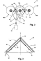
- eine teilweise Seitenansicht des Farbauftragswerk von
Fig. 1 in Blickrichtung y im Bereich der Farbabstreifer: - Fig. 3
- eine Sicht auf die Unterseite eines Farbabstreifers;
- Fig. 4
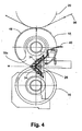
- eine teilweise Seitenansicht eines weiteren Auftragswerks im Be- reich der Abstreifer.
- Ein in
Fig. 1 beispielhaft gezeigtes Farb-, Lack- oder Kleberauftragswerk 10 weist eine Lack, Kleber oder Druckfarbe enthaltende Farbwanne 12 auf, Eine mit ihrer Mantelfläche teilweise in die Wanne 12 eintauchende rotierende Schöpfwalze 16 nimmt den Lack, den Kleber oder die Druckfarbe auf und überträgt diese auf eine Dosierwalze 18. Eine Lack-, Kleber- oder Farbauftragswalze 20 übernimmt den Lack, den Kleber oder die Druckfarbe von der Dosierwalze 18 und gibt sie weiter an eine Übertragungswalze 20, welche den Lack-, Kleber-, Druckfarbe auf einen Druckzylinder bzw. eine Auftragswalze 22 überträgt. Die Auftragswalze 22 überträgt den Lack, den Kleber oder die Druckfarbe auf die Materialbahn mittels einer Formatwalze 14. Die Walzen 14, 16, 18, 20 sowie der Druckzylinder 22 sind über entsprechende Lager- bzw. Antriebswellen 24 in einem in der Zeichnung nicht wiedergegebenen Maschinenständer gelagert und zumindest teilweise angetrieben. Eine gegebenenfalls oszillierende Rakel 26 ist beispielhaft im Bereich der Farbauftragswalze 22 angeordnet. Die sich im wesentlichen über die gesamte Breite der Mantelfläche der Farbauftragswalze 22 erstreckende Rakel 26 dient der gleichmässigen Verteilung des Auftragsmaterials und verdrängt das überschüssige Auftragsmaterial zu den stirnseitigen Enden der Farbauftragswalze 22. - Seitlich am Farbauftragswerk 10 sind zwei einander etwa diametral gegenüberliegende Farbabstreifer 28 so angeordnet, dass diese - wie aus
Fig. 2 ersichtlich - einen Bereich der Stirnfläche 18a beispielweise der Farbauftragswalze 18 und einen Bereich der Stirnfläche 16a der benachbarten Dosierwalze 16 bzw. der Stirnfläche 20a bzw. der benachbarten Übertragungswalze 20 überdecken. Die Farbabstreifer 28 liegen den Stirnflächen 16a, 18a, 20a, 22a an und können über je ein feststehendes Hydraulikelement 30 mit einer voreinstellbaren Andrückkraft beaufschlagt werden. Anstelle eines Hydraulikelementes 30 kann auch ein Pneumatikelement oder eine Federanordnung eingesetzt werden. Aus Gründen einer besseren Übersicht sind die Farbabstreifer 28 nur auf einer Seite der Walzen 16,18, 20, 22 des Farbauftragswerkes 10 eingezeichnet. - Wie in
Fig. 3 gezeigt, bestehen die Farbabstreifer 28 im wesentlichen aus einer Grundplatte 32 aus Aluminium in der Form eines rechtwinklig gleichschenkligen Dreiecks und zwei mit der Grundplatte 32 verschraubten, Auflageflächen bildenden Abstreifelementen 34 aus Messingbronze. Für die Abstreifelemente können auch andere Materialien verwendet werden, wie z.B. Keramik oder andere sog. "weiche" Metalle wie Aluminium. Die von der Grundplatte 32 um wenige Millimeter abragenden Abstreifelemente 34 verlaufen im Randbereich und parallel zu den Katheten der dreieckförmigen Grundplatte 32, laufen in einem rechten Winkel aufeinander einander zu und sind im Bereich der durch die Katheten gebildeten Ecke der Grundplatte 32 unter Bildung eines in der Winkelhalbierenden w liegenden Spaltes 36 voneinander beabstandet. In die Grundplatte 32 ist eine im wesentlichen entlang der innenliegenden Kante 38 der Abstreifelemente 34 verlaufende, kanalartige Vertiefung gefräst. In die kanalartige Vertiefung ist eine an einem Ende verschlossene Lösungrmittelleitung 40 aus Aluminium mit entlang der Leitungsachse von einander beabstandet angeordneten Austrittsöffnungen 42 eingelegt. Die in die kanalartige Vertiefung in der Grundplatte 32 eingelegte Lösungsmittelleitung 40 ist teilweise von den Abstreifelementen 34 übergriffen und auf diese Weise auf der Grundplatte 32 fixiert. - Die Farbabstreifer 28 sind so im Farbauftragswerk 10 angeordnet, dass die Winkelhalbierende w der Grundplatte 32 und der zwischen den beiden aufeinander zulaufenden Abstreifelementen 34 gebildete Spalt 36 etwa in der gemeinsamen Tangentialebene der Berührungslinie des vom Farbabstreifer 28 bearbeiteten Walzenpaares 16, 18 bzw. 18, 20 liegen. Hierbei ragen die Längskanten der beiden Abstreifelemente 34 über die Mantelfläche der beiden Walzen 16, 18 bzw. 18, 20 hinaus und bilden mit den Umfanglinien der Stirnflächen 16a, 18a, 20a einen zum Abstreifen des überschüssigen Auftragsmaterials günstigen Winkel.
- Die Lösungsmittelleitung 40 jedes Farbabstreifers 28 steht mit einem Lösungsmittel-Vorratsbehälter 44 in Verbindung.
- Während des Betriebs des Farbauftragswerkes 10 liegt eines der Abstreifelemente 34 der beiden Farbabstreifer 28 der Stirnfläche 18a der Farbauftragswalze 18 und das andere Abstreifelement 34 der Stirnfläche 16a bzw. 20a der an die Farbauftragswalze 18 angrenzenden Dosierwalze 16 bzw. Übertragungswalze 20 in schleifendern Kontakt an. Vom Lösungsmittel-Vorratsbehälter 44 wird Lösungsmittel über die Lösungsmittelleitung 40 zu den Farbabstreifem 28 geführt und über die Austrittsöffnungen 42 gegen die Stirnflächen 16a, 18, 20a der entsprechenden Walzen 16, 18, 20 gesprüht. Ein Teil des versprühten Lösungsmittels tritt auch in den Spalt 36 zwischen den beiden Abstreifelementen 34 ein, so dass der massgebliche Randbereich der Stirnflächen 16a, 18, 20a der Walzen 16, 18, 20 vollständig mit Lösungsmittel benetzt wird und sich auch zwischen den Laufflächen der Abstreifelemente 34 und den Stirnflächen 16a, 18, 20a ein kontinuierlicher Lösungsmittelfilm ausbilden kann.
- Da das auf die Stirnflächen der Walzen aufgesprühte Lösungsmittel und die von diesem aufgelösten Reste des Auftragsmaterials durch die infolge der schnellen Rotation der Walzen auftretenden Zentrifugalkräfte radial weggeschleudert werden, ist zumindest der Stirnbereich der Farbauftragswalze 18 mit den Abstreifern 28 zusätzlich mit einer Spritzschutzkappe 46 abgedeckt. Die Spritzschutzkappe 46 weist Ableitflächen 48 zur Rückführung des Lösungsmittels und der darin rückgelösten Reste des Auftragsmaterials auf.
- Zusätzlich zu den in die Farbabstreifer 28 integrierten Lösungsmittelleitungen 40 können in Bereichen mit erhöhter Ablagerung von überschüssigem Auftragsmaterial mit dem Lösungsmittel-Vorratsbehälter 44 in Verbindung stehende Lösungsmittelsprührohre 50 mit Auslassöffnungen für das Lösungsmittel angeordnet sein. Ein zwischen die Lösungsmittelleitungen 40 bzw. die Lösungsmittelsprührohre 50 und den Lösungsmittel-Vorratsbehälter 44 geschaltetes Durchflussüberwachungsgerät 52 misst und steuert die Lösungsmittelzufuhr vom Lösungsmittel-Vorratsbehälter 44 zu den Abstreifern 28 in Abhängigkeit von der Umfanggeschwindigkeit der Walzen. Hierzu ist das Durchflussüberwachungsgerät 52 mit einem beispielsweise die Rotationsgeschwindigkeit der Auftragswalze 18 bestimmenden Drehzahlmesser 54 verbunden.
- Bei dem in
Fig. 4 gezeigten Auftragswerk sind die drei Walzen 16, 18, 20 senkrecht übereinander angeordnet Deutlich erkennbar ist die Lage des Abstreifers 28 mit der in der gemeinsamen Tangentialebene der Berührungslinie des vom Abstreifer 28 bearbeiteten Walzenpaares 18, 20 liegenden Winkelhalbierenden w der dreieckförmigen Grundplatte 32 des Abstreifers 28.Fig. 4 zeigt zudem die Übertragung von Auftragsmaterial auf eine durch den Spalt der Walzen 18, 20 geführte und zu bedruckende Materialbahn 56. - Das vorstehend beschriebene und in der Zeichnung dargestellte Auftragswerk 10 mit Abstreifern 28 ist universell einsetzbar und geeignet für die Übertragung einer Vielzahl von lösungsmittelhaltigen Stoffen mittels eines aus Walzen aufgebauten Auftragswerkes auf eine Materialbahn. Neben Druckfarben können dies beispielsweise Kleber, Lacke sowie weitere lösungsmiltelhaltige Materialien sein.
-
- 10
- Farb-, Lack-, oder Kleberauftragswerk
- 12
- Farbwanne
- 14
- Schöpfwalze
- 16
- Dosierwalze
- 16a
- Stirnfläche von 16
- 18
- Farbauftragswalze
- 18a
- Stirnfläche von 18
- 20
- Übertragungswalze
- 20a
- Stirnfläche von 20
- 22
- Druckzylinder
- 24
- Lager- bzw. Antriebswelle
- 26
- Rakel
- 28
- Farbabstreifer
- 30
- Hydraulikelement
- 32
- Grundplatte
- 34
- Abstreifelement
- 36
- Spalt
- 38
- innenliegende Kante von 34
- 40
- Lösungsmittelleitung
- 42
- Austrittsöffnungen
- 44
- Lösungsmittel-Vorratsbehälter
- 46
- Spritzschutzkappe
- 48
- Ableitflächen
- 50
- Lösungsmittelsprührohr
- 52
- Durchflussüberwachungsgerät
- 54
- Drehzahlmesser
- 56
- Materialbahn
- w
- Winkelhalbierende
Claims (5)
- Auftragswerk für lösungsmittelhaltiges Auftragsmaterial, mit einer Vielzahl von lösungsmittelhaltiges Auftragsmaterial führenden Walzen (16, 18, 20), mit wenigstens einem den Stirnflächen (16a, 18a, 20a) der Walzen (16, 18, 20) anliegenden und diese überstreichenden Abstreifer (28) zur Entfernung von überschüssigem, an den Walzenrand verdrängtem Auftragsmaterial,
dadurch gekennzeichnet, dass
von den Abstreifern (28) überstrichene Bereiche der Stirnflächen (16a, 18a, 20a) über Lösungsmittelleitungen (40) mit Lösungsmittel besprühbar sind, jeder Abstreifer (28) eine Grundplatte (32) mit zwei von der Grundplatte (32) abragenden streifenförmigen, in einem Winkel aufeinander zulaufend angeordnet Abstreifelementen (34) aufweist, die beiden Abstreifelemente (34) je einer Walze (16, 18, 20) eines Walzenpaares (16, 18; 18, 20) zugeordnet sind und wenigstens eine mit einem Lösungsmittel-Vorratsbehälter (44) verbundene Lösungsmittelleitung (40) mit wenigstens einer Austrittsöffnung (42) für Lösungsmittel zwischen den zwei Abstreifelementen (34) jedes Abstreifers (28) angeordnet ist. - Auftragswerk nach Anspruch 1, dadurch gekennzeichnet, dass die aufeinander zulaufenden streifenförmige Abstreifelemente (34) unter Bildung eines etwa in Richtung der Winkelhalbierenden (w) verlaufenden Spaltes (36) voneinander beabstandet sind.
- Auftragswerk nach Anspruche 1 oder 2, dadurch gekennzeichnet, dass die Abstreifer (28) mittels eines Druckelementes (30) mit einer definierten Andrückkraft an die Stirnseiten (16a, 18a, 20a) der Walzen (16, 18, 20) anlegbar sind.
- Auftragswerk nach einem der Ansprüche 1 bis 3, dadurch gekennzeichnet, dass ein Durchflussüberwachungsgerät (52) zur Messung und Steuerung der Lösungsmittelzufuhr vom Lösungsmittel-Vorratsbehälter (44) über die Lösungsmittelleitungen (40) zu den Abstreifern (28) angeordnet ist.
- Auftragswerk nach Anspruch 4, dadurch gekennzeichnet, dass die Lösungsmittelzufuhr zu den Abstreifern (28) in Abhängigkeit von der Umfanggeschwindigkeit der Walzen (16, 18, 20) steuerbar ist.
Priority Applications (4)
| Application Number | Priority Date | Filing Date | Title |
|---|---|---|---|
| AT07405333T ATE495013T1 (de) | 2007-11-26 | 2007-11-26 | Auftragswerk für lösungsmittelhaltiges auftragsmaterial |
| DE502007006262T DE502007006262D1 (de) | 2007-11-26 | 2007-11-26 | Auftragswerk für lösungsmittelhaltiges Auftragsmaterial |
| EP07405333A EP2062729B1 (de) | 2007-11-26 | 2007-11-26 | Auftragswerk für lösungsmittelhaltiges Auftragsmaterial |
| ES07405333T ES2359894T3 (es) | 2007-11-26 | 2007-11-26 | Mecanismo de aplicación de material de aplicación que contiene disolvente. |
Applications Claiming Priority (1)
| Application Number | Priority Date | Filing Date | Title |
|---|---|---|---|
| EP07405333A EP2062729B1 (de) | 2007-11-26 | 2007-11-26 | Auftragswerk für lösungsmittelhaltiges Auftragsmaterial |
Publications (2)
| Publication Number | Publication Date |
|---|---|
| EP2062729A1 EP2062729A1 (de) | 2009-05-27 |
| EP2062729B1 true EP2062729B1 (de) | 2011-01-12 |
Family
ID=39133796
Family Applications (1)
| Application Number | Title | Priority Date | Filing Date |
|---|---|---|---|
| EP07405333A Not-in-force EP2062729B1 (de) | 2007-11-26 | 2007-11-26 | Auftragswerk für lösungsmittelhaltiges Auftragsmaterial |
Country Status (4)
| Country | Link |
|---|---|
| EP (1) | EP2062729B1 (de) |
| AT (1) | ATE495013T1 (de) |
| DE (1) | DE502007006262D1 (de) |
| ES (1) | ES2359894T3 (de) |
Families Citing this family (3)
| Publication number | Priority date | Publication date | Assignee | Title |
|---|---|---|---|---|
| KR101341023B1 (ko) * | 2009-12-30 | 2013-12-13 | 엘지디스플레이 주식회사 | 박막 패턴의 제조 장치 및 방법 |
| RU2527092C2 (ru) | 2010-04-02 | 2014-08-27 | Адвенира Энтерпрайзис, Инк. | Устройство для нанесения покрытия валиком |
| DE102012204878A1 (de) * | 2012-03-27 | 2013-10-02 | Achenbach Buschhütten GmbH & Co. KG | Auftragwerk |
Family Cites Families (6)
| Publication number | Priority date | Publication date | Assignee | Title |
|---|---|---|---|---|
| US2511781A (en) * | 1950-06-13 | Gluing machine | ||
| US3097968A (en) * | 1960-11-25 | 1963-07-16 | Schaefer Charles Frederick | Coating applying apparatus |
| DE3117341C2 (de) * | 1981-05-02 | 1988-07-07 | Albert-Frankenthal Ag, 6710 Frankenthal | Farbwerk |
| DE3151005C2 (de) * | 1981-12-23 | 1986-03-13 | Friedrich 4000 Düsseldorf Körner | Tiefdruckmaschine |
| WO1991006428A1 (en) * | 1989-10-26 | 1991-05-16 | Adolph Coors Company | Fountain roll apparatus |
| DE10018995A1 (de) * | 2000-04-17 | 2001-11-08 | Windmoeller & Hoelscher | Druckmaschine |
-
2007
- 2007-11-26 AT AT07405333T patent/ATE495013T1/de active
- 2007-11-26 DE DE502007006262T patent/DE502007006262D1/de active Active
- 2007-11-26 EP EP07405333A patent/EP2062729B1/de not_active Not-in-force
- 2007-11-26 ES ES07405333T patent/ES2359894T3/es active Active
Also Published As
| Publication number | Publication date |
|---|---|
| ATE495013T1 (de) | 2011-01-15 |
| ES2359894T3 (es) | 2011-05-27 |
| DE502007006262D1 (de) | 2011-02-24 |
| EP2062729A1 (de) | 2009-05-27 |
Similar Documents
| Publication | Publication Date | Title |
|---|---|---|
| DE1652366C3 (de) | Vorrichtung zum Beschichten von Blättern | |
| EP2878382B1 (de) | Verfahren und Vorrichtung zum Auftragen eines fliessfähigen Stoffes | |
| EP0520305B1 (de) | Wascheinrichtung für Farbwerke bei Druckmaschinen | |
| EP0399147B1 (de) | Vorrichtung zum Beschichten einer um eine Gegenwalze geführten Materialbahn | |
| DE4239793A1 (de) | ||
| EP2062729A1 (de) | Auftragswerk für lösungsmittelhaltiges Auftragsmaterial | |
| DE102019106642A1 (de) | Vorrichtung zum Abtragen von Schmelzklebstoff | |
| EP0623465B1 (de) | Umschaltbare Lackversorgung an Veredelungseinheiten in Rotationsdruckmaschinen | |
| DE102022121229A1 (de) | Farbwerk mit einer Schmiermittelzufuhr und Verfahren zum Abdichten einer Farbwanne | |
| EP2646169B1 (de) | Vorrichtung zum beschichten von papier- oder kartonbahnen | |
| EP1607141B1 (de) | Auftragsvorrichtung | |
| EP1040922B1 (de) | Verfahren und Vorrichtung zum Entfernen von Farbe aus einem einseitig offenen Behälter | |
| DE10253194A1 (de) | Vorrichtung und Verfahren zum Einfärben der Walze einer Rotationsdruckmaschine | |
| EP0428889B1 (de) | Kurzfarbwerk mit einer Rasterwalze | |
| CH641091A5 (en) | Damping unit | |
| DE102011008487A1 (de) | Farbdosiereinrichtung einer Druckmaschine | |
| EP0839652B1 (de) | Verfahren zur Reinigung von Zylindern und Walzen in einer Druckmaschine | |
| EP0728241A1 (de) | Auftragswerk zum direkten oder indirekten auftragen eines flüssigen oder pastösen mediums auf eine laufende materialbahn | |
| DE102005010207A1 (de) | Lackiervorrichtung für ein Druckwerk einer Rotationsdruckmaschine | |
| DE10303608B4 (de) | Verfahren für einen stabilen Maschinenlauf an Druckeinheiten einer Rotationsdruckmaschine für den Betrieb mit teilbreitem Bedruckstoff | |
| EP1043155B1 (de) | Einrichtung zum Dosieren flüssiger Medien | |
| DE102008042263B4 (de) | Vorrichtung zum Aufbringen von Druckfarbe | |
| EP1591250B1 (de) | Verfahren und Vorrichtungen zum Abstreifen eines Fluids von einer Walze | |
| EP1698464B1 (de) | Lackiervorrichtung für ein Druckwerk einer Rotationsdruckmaschine | |
| EP1149700B1 (de) | Dosiersystem für eine Beschichtungseinheit in einer Druckmaschine |
Legal Events
| Date | Code | Title | Description |
|---|---|---|---|
| PUAI | Public reference made under article 153(3) epc to a published international application that has entered the european phase |
Free format text: ORIGINAL CODE: 0009012 |
|
| AK | Designated contracting states |
Kind code of ref document: A1 Designated state(s): AT BE BG CH CY CZ DE DK EE ES FI FR GB GR HU IE IS IT LI LT LU LV MC MT NL PL PT RO SE SI SK TR |
|
| AX | Request for extension of the european patent |
Extension state: AL BA HR MK RS |
|
| 17P | Request for examination filed |
Effective date: 20091127 |
|
| 17Q | First examination report despatched |
Effective date: 20091228 |
|
| AKX | Designation fees paid |
Designated state(s): AT BE BG CH CY CZ DE DK EE ES FI FR GB GR HU IE IS IT LI LT LU LV MC MT NL PL PT RO SE SI SK TR |
|
| RBV | Designated contracting states (corrected) |
Designated state(s): AT BE BG CH CY CZ DE DK EE ES FI FR GB GR HU IE IS IT LI LT LU LV MC MT NL PL PT RO SE SI SK TR |
|
| GRAP | Despatch of communication of intention to grant a patent |
Free format text: ORIGINAL CODE: EPIDOSNIGR1 |
|
| GRAC | Information related to communication of intention to grant a patent modified |
Free format text: ORIGINAL CODE: EPIDOSCIGR1 |
|
| RAP1 | Party data changed (applicant data changed or rights of an application transferred) |
Owner name: ALCAN TECHNOLOGY & MANAGEMENT LTD. |
|
| RAP1 | Party data changed (applicant data changed or rights of an application transferred) |
Owner name: AMCOR FLEXIBLES KREUZLINGEN LTD. |
|
| GRAS | Grant fee paid |
Free format text: ORIGINAL CODE: EPIDOSNIGR3 |
|
| GRAA | (expected) grant |
Free format text: ORIGINAL CODE: 0009210 |
|
| AK | Designated contracting states |
Kind code of ref document: B1 Designated state(s): AT BE BG CH CY CZ DE DK EE ES FI FR GB GR HU IE IS IT LI LT LU LV MC MT NL PL PT RO SE SI SK TR |
|
| REG | Reference to a national code |
Ref country code: GB Ref legal event code: FG4D Free format text: NOT ENGLISH |
|
| REG | Reference to a national code |
Ref country code: CH Ref legal event code: EP |
|
| REG | Reference to a national code |
Ref country code: IE Ref legal event code: FG4D Free format text: LANGUAGE OF EP DOCUMENT: GERMAN |
|
| REF | Corresponds to: |
Ref document number: 502007006262 Country of ref document: DE Date of ref document: 20110224 Kind code of ref document: P |
|
| REG | Reference to a national code |
Ref country code: DE Ref legal event code: R096 Ref document number: 502007006262 Country of ref document: DE Effective date: 20110224 |
|
| REG | Reference to a national code |
Ref country code: NL Ref legal event code: VDEP Effective date: 20110112 |
|
| REG | Reference to a national code |
Ref country code: ES Ref legal event code: FG2A Ref document number: 2359894 Country of ref document: ES Kind code of ref document: T3 Effective date: 20110527 |
|
| LTIE | Lt: invalidation of european patent or patent extension |
Effective date: 20110112 |
|
| PG25 | Lapsed in a contracting state [announced via postgrant information from national office to epo] |
Ref country code: LT Free format text: LAPSE BECAUSE OF FAILURE TO SUBMIT A TRANSLATION OF THE DESCRIPTION OR TO PAY THE FEE WITHIN THE PRESCRIBED TIME-LIMIT Effective date: 20110112 Ref country code: IS Free format text: LAPSE BECAUSE OF FAILURE TO SUBMIT A TRANSLATION OF THE DESCRIPTION OR TO PAY THE FEE WITHIN THE PRESCRIBED TIME-LIMIT Effective date: 20110512 Ref country code: LV Free format text: LAPSE BECAUSE OF FAILURE TO SUBMIT A TRANSLATION OF THE DESCRIPTION OR TO PAY THE FEE WITHIN THE PRESCRIBED TIME-LIMIT Effective date: 20110112 Ref country code: PT Free format text: LAPSE BECAUSE OF FAILURE TO SUBMIT A TRANSLATION OF THE DESCRIPTION OR TO PAY THE FEE WITHIN THE PRESCRIBED TIME-LIMIT Effective date: 20110512 Ref country code: SE Free format text: LAPSE BECAUSE OF FAILURE TO SUBMIT A TRANSLATION OF THE DESCRIPTION OR TO PAY THE FEE WITHIN THE PRESCRIBED TIME-LIMIT Effective date: 20110112 Ref country code: GR Free format text: LAPSE BECAUSE OF FAILURE TO SUBMIT A TRANSLATION OF THE DESCRIPTION OR TO PAY THE FEE WITHIN THE PRESCRIBED TIME-LIMIT Effective date: 20110413 |
|
| REG | Reference to a national code |
Ref country code: IE Ref legal event code: FD4D |
|
| PG25 | Lapsed in a contracting state [announced via postgrant information from national office to epo] |
Ref country code: BG Free format text: LAPSE BECAUSE OF FAILURE TO SUBMIT A TRANSLATION OF THE DESCRIPTION OR TO PAY THE FEE WITHIN THE PRESCRIBED TIME-LIMIT Effective date: 20110412 Ref country code: PL Free format text: LAPSE BECAUSE OF FAILURE TO SUBMIT A TRANSLATION OF THE DESCRIPTION OR TO PAY THE FEE WITHIN THE PRESCRIBED TIME-LIMIT Effective date: 20110112 Ref country code: CY Free format text: LAPSE BECAUSE OF FAILURE TO SUBMIT A TRANSLATION OF THE DESCRIPTION OR TO PAY THE FEE WITHIN THE PRESCRIBED TIME-LIMIT Effective date: 20110112 Ref country code: NL Free format text: LAPSE BECAUSE OF FAILURE TO SUBMIT A TRANSLATION OF THE DESCRIPTION OR TO PAY THE FEE WITHIN THE PRESCRIBED TIME-LIMIT Effective date: 20110112 Ref country code: SI Free format text: LAPSE BECAUSE OF FAILURE TO SUBMIT A TRANSLATION OF THE DESCRIPTION OR TO PAY THE FEE WITHIN THE PRESCRIBED TIME-LIMIT Effective date: 20110112 Ref country code: FI Free format text: LAPSE BECAUSE OF FAILURE TO SUBMIT A TRANSLATION OF THE DESCRIPTION OR TO PAY THE FEE WITHIN THE PRESCRIBED TIME-LIMIT Effective date: 20110112 |
|
| PG25 | Lapsed in a contracting state [announced via postgrant information from national office to epo] |
Ref country code: IE Free format text: LAPSE BECAUSE OF FAILURE TO SUBMIT A TRANSLATION OF THE DESCRIPTION OR TO PAY THE FEE WITHIN THE PRESCRIBED TIME-LIMIT Effective date: 20110112 Ref country code: EE Free format text: LAPSE BECAUSE OF FAILURE TO SUBMIT A TRANSLATION OF THE DESCRIPTION OR TO PAY THE FEE WITHIN THE PRESCRIBED TIME-LIMIT Effective date: 20110112 Ref country code: DK Free format text: LAPSE BECAUSE OF FAILURE TO SUBMIT A TRANSLATION OF THE DESCRIPTION OR TO PAY THE FEE WITHIN THE PRESCRIBED TIME-LIMIT Effective date: 20110112 |
|
| PLBE | No opposition filed within time limit |
Free format text: ORIGINAL CODE: 0009261 |
|
| STAA | Information on the status of an ep patent application or granted ep patent |
Free format text: STATUS: NO OPPOSITION FILED WITHIN TIME LIMIT |
|
| PG25 | Lapsed in a contracting state [announced via postgrant information from national office to epo] |
Ref country code: RO Free format text: LAPSE BECAUSE OF FAILURE TO SUBMIT A TRANSLATION OF THE DESCRIPTION OR TO PAY THE FEE WITHIN THE PRESCRIBED TIME-LIMIT Effective date: 20110112 Ref country code: CZ Free format text: LAPSE BECAUSE OF FAILURE TO SUBMIT A TRANSLATION OF THE DESCRIPTION OR TO PAY THE FEE WITHIN THE PRESCRIBED TIME-LIMIT Effective date: 20110112 Ref country code: SK Free format text: LAPSE BECAUSE OF FAILURE TO SUBMIT A TRANSLATION OF THE DESCRIPTION OR TO PAY THE FEE WITHIN THE PRESCRIBED TIME-LIMIT Effective date: 20110112 |
|
| 26N | No opposition filed |
Effective date: 20111013 |
|
| REG | Reference to a national code |
Ref country code: DE Ref legal event code: R097 Ref document number: 502007006262 Country of ref document: DE Effective date: 20111013 |
|
| BERE | Be: lapsed |
Owner name: AMCOR FLEXIBLES KREUZLINGEN LTD. Effective date: 20111130 |
|
| PG25 | Lapsed in a contracting state [announced via postgrant information from national office to epo] |
Ref country code: MC Free format text: LAPSE BECAUSE OF NON-PAYMENT OF DUE FEES Effective date: 20111130 |
|
| REG | Reference to a national code |
Ref country code: CH Ref legal event code: PL |
|
| GBPC | Gb: european patent ceased through non-payment of renewal fee |
Effective date: 20111126 |
|
| PG25 | Lapsed in a contracting state [announced via postgrant information from national office to epo] |
Ref country code: LI Free format text: LAPSE BECAUSE OF NON-PAYMENT OF DUE FEES Effective date: 20111130 Ref country code: CH Free format text: LAPSE BECAUSE OF NON-PAYMENT OF DUE FEES Effective date: 20111130 |
|
| PG25 | Lapsed in a contracting state [announced via postgrant information from national office to epo] |
Ref country code: BE Free format text: LAPSE BECAUSE OF NON-PAYMENT OF DUE FEES Effective date: 20111130 |
|
| PG25 | Lapsed in a contracting state [announced via postgrant information from national office to epo] |
Ref country code: GB Free format text: LAPSE BECAUSE OF NON-PAYMENT OF DUE FEES Effective date: 20111126 |
|
| PG25 | Lapsed in a contracting state [announced via postgrant information from national office to epo] |
Ref country code: MT Free format text: LAPSE BECAUSE OF FAILURE TO SUBMIT A TRANSLATION OF THE DESCRIPTION OR TO PAY THE FEE WITHIN THE PRESCRIBED TIME-LIMIT Effective date: 20110112 |
|
| PG25 | Lapsed in a contracting state [announced via postgrant information from national office to epo] |
Ref country code: LU Free format text: LAPSE BECAUSE OF NON-PAYMENT OF DUE FEES Effective date: 20111126 |
|
| PG25 | Lapsed in a contracting state [announced via postgrant information from national office to epo] |
Ref country code: TR Free format text: LAPSE BECAUSE OF FAILURE TO SUBMIT A TRANSLATION OF THE DESCRIPTION OR TO PAY THE FEE WITHIN THE PRESCRIBED TIME-LIMIT Effective date: 20110112 |
|
| PG25 | Lapsed in a contracting state [announced via postgrant information from national office to epo] |
Ref country code: HU Free format text: LAPSE BECAUSE OF FAILURE TO SUBMIT A TRANSLATION OF THE DESCRIPTION OR TO PAY THE FEE WITHIN THE PRESCRIBED TIME-LIMIT Effective date: 20110112 |
|
| REG | Reference to a national code |
Ref country code: FR Ref legal event code: PLFP Year of fee payment: 9 |
|
| REG | Reference to a national code |
Ref country code: FR Ref legal event code: PLFP Year of fee payment: 10 |
|
| REG | Reference to a national code |
Ref country code: FR Ref legal event code: PLFP Year of fee payment: 11 |
|
| REG | Reference to a national code |
Ref country code: FR Ref legal event code: PLFP Year of fee payment: 12 |
|
| PGFP | Annual fee paid to national office [announced via postgrant information from national office to epo] |
Ref country code: IT Payment date: 20221123 Year of fee payment: 16 Ref country code: FR Payment date: 20221123 Year of fee payment: 16 Ref country code: ES Payment date: 20221201 Year of fee payment: 16 Ref country code: DE Payment date: 20221125 Year of fee payment: 16 Ref country code: AT Payment date: 20221102 Year of fee payment: 16 |
|
| REG | Reference to a national code |
Ref country code: DE Ref legal event code: R119 Ref document number: 502007006262 Country of ref document: DE |
|
| REG | Reference to a national code |
Ref country code: AT Ref legal event code: MM01 Ref document number: 495013 Country of ref document: AT Kind code of ref document: T Effective date: 20231126 |
|
| PG25 | Lapsed in a contracting state [announced via postgrant information from national office to epo] |
Ref country code: AT Free format text: LAPSE BECAUSE OF NON-PAYMENT OF DUE FEES Effective date: 20231126 |
|
| PG25 | Lapsed in a contracting state [announced via postgrant information from national office to epo] |
Ref country code: AT Free format text: LAPSE BECAUSE OF NON-PAYMENT OF DUE FEES Effective date: 20231126 |
|
| PG25 | Lapsed in a contracting state [announced via postgrant information from national office to epo] |
Ref country code: DE Free format text: LAPSE BECAUSE OF NON-PAYMENT OF DUE FEES Effective date: 20240601 |
|
| PG25 | Lapsed in a contracting state [announced via postgrant information from national office to epo] |
Ref country code: FR Free format text: LAPSE BECAUSE OF NON-PAYMENT OF DUE FEES Effective date: 20231130 |
|
| PG25 | Lapsed in a contracting state [announced via postgrant information from national office to epo] |
Ref country code: FR Free format text: LAPSE BECAUSE OF NON-PAYMENT OF DUE FEES Effective date: 20231130 Ref country code: DE Free format text: LAPSE BECAUSE OF NON-PAYMENT OF DUE FEES Effective date: 20240601 |
|
| PG25 | Lapsed in a contracting state [announced via postgrant information from national office to epo] |
Ref country code: IT Free format text: LAPSE BECAUSE OF NON-PAYMENT OF DUE FEES Effective date: 20231126 |
|
| PG25 | Lapsed in a contracting state [announced via postgrant information from national office to epo] |
Ref country code: IT Free format text: LAPSE BECAUSE OF NON-PAYMENT OF DUE FEES Effective date: 20231126 |
|
| REG | Reference to a national code |
Ref country code: ES Ref legal event code: FD2A Effective date: 20250103 |
|
| PG25 | Lapsed in a contracting state [announced via postgrant information from national office to epo] |
Ref country code: ES Free format text: LAPSE BECAUSE OF NON-PAYMENT OF DUE FEES Effective date: 20231127 |
|
| PG25 | Lapsed in a contracting state [announced via postgrant information from national office to epo] |
Ref country code: ES Free format text: LAPSE BECAUSE OF NON-PAYMENT OF DUE FEES Effective date: 20231127 |