EP2061620B1 - SCHWEIßVERFAHREN ZUR DURCHFÜHRUNG EINES SCHWEIßPROZESSES - Google Patents
SCHWEIßVERFAHREN ZUR DURCHFÜHRUNG EINES SCHWEIßPROZESSES Download PDFInfo
- Publication number
- EP2061620B1 EP2061620B1 EP07800164.1A EP07800164A EP2061620B1 EP 2061620 B1 EP2061620 B1 EP 2061620B1 EP 07800164 A EP07800164 A EP 07800164A EP 2061620 B1 EP2061620 B1 EP 2061620B1
- Authority
- EP
- European Patent Office
- Prior art keywords
- welding
- control
- time
- values
- variable
- Prior art date
- Legal status (The legal status is an assumption and is not a legal conclusion. Google has not performed a legal analysis and makes no representation as to the accuracy of the status listed.)
- Active
Links
Images


Classifications
-
- B—PERFORMING OPERATIONS; TRANSPORTING
- B23—MACHINE TOOLS; METAL-WORKING NOT OTHERWISE PROVIDED FOR
- B23K—SOLDERING OR UNSOLDERING; WELDING; CLADDING OR PLATING BY SOLDERING OR WELDING; CUTTING BY APPLYING HEAT LOCALLY, e.g. FLAME CUTTING; WORKING BY LASER BEAM
- B23K9/00—Arc welding or cutting
- B23K9/095—Monitoring or automatic control of welding parameters
- B23K9/0956—Monitoring or automatic control of welding parameters using sensing means, e.g. optical
-
- B—PERFORMING OPERATIONS; TRANSPORTING
- B23—MACHINE TOOLS; METAL-WORKING NOT OTHERWISE PROVIDED FOR
- B23K—SOLDERING OR UNSOLDERING; WELDING; CLADDING OR PLATING BY SOLDERING OR WELDING; CUTTING BY APPLYING HEAT LOCALLY, e.g. FLAME CUTTING; WORKING BY LASER BEAM
- B23K9/00—Arc welding or cutting
- B23K9/12—Automatic feeding or moving of electrodes or work for spot or seam welding or cutting
- B23K9/124—Circuits or methods for feeding welding wire
- B23K9/125—Feeding of electrodes
Definitions
- the invention relates to a method for arc welding, according to the preamble of claims 1, 2, 3 and 12.
- arc welding method for performing welding processes in a, with an arc melting welding wire known.
- an arc burns between the current-carrying wire electrode and the workpiece under protective gas, whereby the machine-fed wire serves as an electrode and melts in its own arc.
- a temporally pulsed voltage or current profile can be provided by the control device of the welding current wave.
- arc welding methods are known in which the wire feed movement is superimposed on a precisely controlled oscillatory movement in the forward or backward direction.
- the invention is therefore an object of the invention to provide a welding device or a welding method for performing welding processes with a, in an arc welding wire, with the increased reliability can be achieved or damage to the welding machine can be avoided or kept low due to malfunction can.
- a welding method for performing and monitoring a welding process is defined in which a first and a second time interval with different durations and a sampling rate for determining the values of the characteristic, and with each sampling, the values of the characteristic are stored, which at one time from the control device determining, from the stored values of the characteristic which are in the relatively earlier time intervals, a first average and a second average as the control quantity, whereupon an upper and lower limit value is calculated from the first average of the first time interval, and whereupon the control quantity is compared with the upper and lower limit values.
- the position of the time intervals may be selected to be immediately preceding relative to the respectively last determined value of the parameter, but it is also possible for the time intervals to be arranged earlier in time relative to the last-determined value of the parameter with a specific time difference.
- a major advantage of this control method is that it allows the limit values to be set as close as possible to the other characteristic, so that a very small window is formed.
- the object of the invention is achieved independently by the welding method according to claim 2. It is provided that a time interval with a duration and a sampling rate for determining the values of the characteristic is determined, and that with each sampling the values of the characteristic are stored, followed at a time (40) by the control device from the stored values of the characteristic which are in the time interval relatively earlier than the time (40), an average value is calculated, and the last-measured value of the characteristic is used as the control quantity, whereupon an upper and a lower limit value are calculated from the mean value of the time interval, and then the control size is compared to the upper and lower limits.
- a first and a second number of values to be recorded of the characteristic and a sampling rate for determining the values of the characteristic are determined, the second number being smaller than the first number, and that with each sampling, the values of the characteristic are stored, whereupon, at a time from the controller, from the stored values of the characteristic which are earlier relative to the time, a first average and a second average are calculated as the control quantity, starting from first average of the first number, an upper and a lower limit, and then comparing the control with the upper and lower limits.
- a welding method for carrying out a welding process is provided with a welding wire melting in an arc, which is supplied with energy from at least one regulated current source, wherein control of the current source and a feed device for the welding wire is performed by a control device. It is further provided that during the welding process from parameters of the arc or the welding process, such as welding current, welding voltage or resistance, at least one control variable is measured or calculated, recorded over the duration of a predeterminable time interval values of the control variable or stored in the control device become. From these values lying in the time interval, an average value of the control variable is then calculated and, based thereon, an upper and / or a lower limit value is determined.
- a control signal is generated by the control device by the current value of the control variable.
- the welding process is then interrupted by the control device or a state report of states of the welding process is generated.
- Such status messages can relate, for example, to the wire feed, the state of the welding torch and the workpiece quality.
- the mean value as well as the upper or the lower limit value is recalculated consecutively in time, in which the time interval lying before the current value of the control variable is carried along in time. In order to determine the mean value of the control variable, those values or individual values of the control variable thus contribute, which are currently in the time window determined by the time interval.
- the control signal is generated after exceeding the upper limit or below the lower limit for the duration of an observation time that is longer than a predefined control time.
- a control of the feed device for changing the feed rate Vd of the welding wire is triggered by the control signal.
- a control of a cooling device for changing the cooling power for a welding torch of the welding device is triggered by the control signal.
- an interruption of the welding process is triggered by the control signal. This has the advantage that damage to the welding device, in particular damage to the welding torch or to the contact tube of the welding torch, due to blockages during the advance of the welding wire can be prevented.
- a periodic voltage waveform of the welding voltage U (t) minimum points are determined. These indicate shorts in the arc of the arc welding process. From the number of minimum positions occurring during a preselectable time interval preceding each of the current observation time, a frequency H (t) of shorts occurring in the arc is calculated, and this frequency H (t) is used as a control quantity.
- a minimum frequency Hmin is set as a lower limit or a maximum frequency Hmax as an upper limit for the current frequency H (t) before carrying out a welding process.
- the thus provided use of the frequency H (t) as a control variable allows monitoring of the welding process, without the knowledge of the absolute values of welding current or welding voltage are required.
- a time sequence of period durations TB is measured or determined by a periodic voltage curve of the welding voltage U (t) or in a periodic current profile of the welding current I (t), this sequence Periods TB is used as a control variable.
- a minimum period TBmin is set as the lower limit or a maximum period TBmax as the upper limit for the sequence of the periods TB.
- a momentary resistance R (t) is calculated from the welding voltage U (t) and from the welding current I (t), in which case this resistance R (t) is used as the control variable.
- a time-invariant minimum resistance RAmin is defined as the lower limit or a time-invariable maximum resistance RAmax as the upper limit for the instantaneous resistance R (t).
- a time-varying minimum resistance Rmin (t) is calculated as the lower limit or a time-varying maximum resistance Rmax as the upper limit for the instantaneous resistance R (t).
- the maximum resistance Rmax (t) is calculated from the sum of a mean resistance RM (t) and an upper resistance difference EO and that the minimum resistance Rmin is calculated from the difference of the mean resistance RM (t) and a lower resistance difference Reu is calculated.
- the average resistance RM (t) is determined by averaging the instantaneous resistance R (t) over a time interval TI.
- the upper and the lower resistance difference Reo, Reu thus determine a tolerance range for the instantaneous resistance R (t) whose position is also temporally variable according to the time change of the mean resistance RM (t). This allows the determination of a relatively narrow tolerance range for the instantaneous resistance R (t) and a high flexibility of the welding process or monitoring, by not having to set these limits absolutely.
- the resistance R (t) is calculated by averaging over at least one period TB of the periodic voltage curve of the welding voltage U (t) or of the periodic current profile of the welding current U (t). This has the advantage that it avoids or, to a certain extent, suppresses fluctuations that are not or only slightly significant over the course of time of the resistor R (t).
- time-invariant minimum resistance RAmin and the time-invariant maximum resistance RAmax are used for the duration of a start interval TS starting from a start time of the welding process for monitoring the welding process, and for the welding process phases following the start interval TS time-varying minimum resistance Rmin (t) and maximum resistance Rmax (t) are used.
- a lower limit which starts from the minimum resistance RAmin and increases continuously and a upper limit of maximum resistance RAmax emanates and continuously drops, is used to monitor the welding process.
- the number of leakage of the resistor R (t) from the range between the minimum resistance Rmin (t) and the maximum resistance Rmax (t) is determined and this number as a further control variable is used.
- a number of outputs of the resistor R (t) from a range between the minimum resistance RAmin and the maximum resistance RAmax is determined and this number is also used as a further control variable. This allows the early detection of a slowly progressive formation of defects or operational anomalies of the welding machine.
- a welding method for carrying out a welding process with a welding wire which melts in an arc and which is supplied with energy from at least one regulated current source is provided. Via a control device, a control of the power source and a feed device for the welding wire, wherein during the welding process, the welding voltage U (t) is measured.
- minimum points, in particular occurring short circuits are determined in the periodic voltage curve of the welding voltage U (t), and a period TP between two successive minimum positions is calculated.
- a control signal and depending on this control signal the welding process interrupted or a status message of states of the welding process, such as the wire feed, the state of the welding torch or the Workpiece quality, generated.
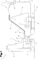
- a welding system or a welding machine 1 for performing welding processes or welding processes for arc welding, such as MIG / MAG welding or pulse welding shown.
- the welding apparatus 1 comprises a power source 2 with a power part 3 and a control device 4.
- the control device 4 is connected to a control valve 5 in connection.
- This control valve 5 is arranged in a supply line 6 for a gas 7 between a gas storage 8 and a welding torch 9.
- the gas 7 is in particular a protective gas, such as CO 2 , helium, argon or the like.
- control device 4 can further a feed device 10 for a welding wire 11 are driven.
- the welding wire 11 is supplied via a supply line 12 from a supply drum 13 in the region of the welding torch 9.
- the feed device 10 can also be integrated in the welding device 1.
- the power for generating an arc 15 between the welding wire 11 and a workpiece 16 to the welding torch 9 and the welding wire 11 is supplied from the power unit 3 of the power source 2.
- the workpiece to be welded 16 is also connected via a further supply line 17 to the welding device 1 and the power source 2 and can thus be built on the arc 15, a closed circuit.
- the welding device 1 may further be equipped with a cooling device 18, wherein via a cooling circuit 19, with the interposition of a flow monitor 20 and a liquid pump, liquid from a coolant tank 21 to the welding torch 9 can be supplied to the cooling.
- an input and / or output device 22 is provided on the welding device 1.
- the operating modes and / or welding parameters set via the input and / or output device 22 are then forwarded to the control device 4 and the individual components of the welding system or of the welding device 1 are subsequently controlled by the latter.
- the individual, the welding device 1 with the welding torch 9 connecting lines are preferably guided or bundled in a hose package 23.
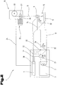
- the Fig. 2 shows a schematic diagram of the welding circuit or the welding device 1 in conjunction with a workpiece 16 to be welded.
- the individual components of the power section 3 and the power source 2 and the control device 4 are arranged integrated in the welding device 1.
- the power source 2 is connected to the welding torch 9 or the workpiece 16 via the supply lines 14, 17.
- the control device 4 is connected via a control line 24 also with the feed device 10 in connection and can be done so an automated control of the feed device 10 and the supply of the welding wire 11.
- a feed speed "Vd" can be achieved. of the welding wire 11 are controlled.
- a monitoring of the electrical variables of the welding circuit is provided.
- the control device 4 has a measuring device 28 with the aid of which instantaneous values of a welding current I (t) 29 and a welding voltage U (t) 30 can be measured.
- the measuring device 28 is connected via measuring lines 31, 32 to output terminals 33, 34 of the current source 2, and thus a terminal voltage UK (t) 35 can be measured.
- the terminal voltage UK (t) 35 can be used as representative of the welding voltage U (t) 30 and it is therefore not necessary the measuring lines 31, 32 to the welding torch 9 or lead to the workpiece 16 (dashed lines drawn).
- the welding voltage U (t) 30 can also be measured directly by contacting the measuring lines 31, 32 on the welding torch 9 or the workpiece 15.
- a first embodiment of the welding method according to the invention will be described.
- the time profile of the welding voltage U (t) 30 is shown for a normal arc welding process, whereas in the following 4 and 5 an arc welding process with a so-called short arc is described.
- the welding voltage 30 At the time course of the welding process after Fig. 3 is the welding voltage 30 until a time corresponding to a currently measured with the measuring device 28 value of the characteristic 100, which is symbolized schematically by a dashed line shown. Furthermore, the temporal adjoining course of the welding voltage 30 was drawn for better understanding by a dashed line in the diagram. Basically, it should be mentioned that in the definition of the characteristic 100, the value or calculated value of one or more welding parameters, ie the welding voltage, the welding current, the resistance, the power, etc. corresponds to the calculated value and in the illustrated embodiment in FIG Fig. 3 the welding voltage 30 is taken as an example.
- a first time interval 101 and a second time interval 102 and a sampling rate 103 which is schematically symbolized by arrows, for determining the characteristics 100, ie, that of the control device 4 after the commissioning of the welding machine 1, the duration for the time intervals 101 and 102 and the frequency for the sampling rate 103 at which a determination of the characteristics 100 is to take place is determined.
- the data can be stored in a memory and / or set or changed by a user.
- the time durations for the time intervals 101 and 102 differ substantially, the first time interval 101 being longer than the second time interval 30.
- the first time interval can last 0.5 seconds and the second time interval 0.1 seconds.
- the sampling rate 103 may, for example, have a frequency of 20 kHz.
- the first time interval has a duration between 0.3 and 1.0 seconds and the second time interval has a duration between 0.05 and 0.3 seconds.
- the control device 4 or the measuring device 28 at any time of the sampling rate 103 determines a value of the parameter 100, ie that due to the fixed frequency of the sampling rate 103, a constant determination of the characteristic 100 takes place and this is stored.
- a value of the parameter 100 ie that due to the fixed frequency of the sampling rate 103
- a constant determination of the characteristic 100 takes place and this is stored.
- the control device 4 only those stored values of the parameter 100 for the further calculation which are earlier in time with respect to the instantaneous value of the parameter 100 within the time intervals 101 and 102 are taken into account by the control device 4.
- the other previously determined values of characteristic 100 can be stored, for example for quality control, they are not required for the control method according to the invention.
- time intervals 101 and 102 are coupled to the current or current parameter 100 and the time intervals 101 and 102, or the measured variables 100 contained therein, are carried along with the instantaneous parameter 100 during the welding process.
- the controller 4 derives from these values of the parameter 100 within the time intervals 101 and 102 a first average value 106 for the first time interval 101 and a second mean value 107 for the second time interval 102 are calculated. Subsequently, starting from the first mean value 106 of the first time interval 101, an upper and a lower limit value 104 and 105 are calculated. The second mean value 107 for the second time interval 102 is used as the control quantity and compared with the upper and lower limit values 104 and 105.
- the limit values 104 and 105 are preferably set as close as possible to the first mean value 106, that is, for example, an increase or decrease of 10% is made from the mean value 106, so that a tolerance window that is as narrow as possible is determined. It is possible that the determination or calculation of the limit values 104 and 105 in dependence on further set welding parameters, such as depending on the material to be welded, the welding wire, etc., takes place differently.
- the duration of the second time interval 102 is chosen so short that only a single value of the characteristic 100 is therein, so that the control is performed with the last detected value of the characteristic 100, which thus simultaneously forms the control variable.
- a second time interval 102 for the comparison of the characteristic 100 with the calculated limit values 101 and 102 is therefore advantageous since, in a welding process, transient process state changes, such as, for example, contamination on the workpiece 16, etc., often occur However, parameter 100 do not have any significant impact on the process. In other words, if only the last determined value of the parameter 100 is used, then it changes frequently and then exceeds the limit values 101 and 102, as a result of which an action which would actually not be required is started by the control device 4. So that this does not occur constantly, the second time interval 102 is introduced into the control process with a much shorter duration, so that in turn an average value 107 can be used for the comparison with the limit values 101 and 102 and thus short-term strong changes do not immediately take effect.
- an identifiable configuration instead of the first and the second time interval 101 and 102 is a selectable number of values of the characteristic 100 is used, that is, for example, the first number of 1000 values of the characteristic 100 and the second number of 10 values the characteristic 100 consists of which then the averages 106, 107 are formed.
- This can be formed, for example, in a simple form by a kind of shift register, in which the last detected values of the parameter 100 are always added, as a result of which the values of the parameter 100 which are farthest in time are omitted. It is also possible that this procedure is also performed with a memory known from the prior art, the so-called first-in-last-out.
- average values 106, 107 are formed from a defined number of determined welding process data, with limit values 104 and 105 being as close as possible to the first average value 106, which is formed from a substantially larger number of values at the first average 106, and these thresholds 104 and 105 are compared to the second average 107 formed from substantially fewer values.
- This averaging can be done by a variety of welding parameters, such as short circuits, welding current, welding voltage, a calculated or determined resistance, a calculated or determined power, etc. ,.
- FIG. 4 is a diagram of the time course of the welding voltage U (t) 30 for an arc welding process with a so-called short arc shown.
- the melting of the welding wire 11 into the arc 15 results in the formation of a liquid metal droplet which briefly forms an electrical short circuit between the welding wire 11 and the workpiece 16 or the molten bath on the workpiece 16 when it is detached from the welding wire 11 , This has the consequence that the welding voltage U (t) 30 drops sharply during short-circuiting or for the duration of the short circuit.
- the welding voltage U (t) 30 rises again. This results in a periodic succession of low or high values of the welding voltage U (t) 30, with which in the diagram of FIG Fig. 4 In this case, short-circuits are recognizable by curves of the welding voltage U (t) 30 with low values.
- a stable welding process course has an approximately constant number of short circuits during a time interval T. However, in a real welding process, this number will vary with time.
- Fig. 5 shows a diagram with the time course of a frequency H (t) 37 of the occurrence of short circuits during the time interval T according to Fig. 4 ,
- the instantaneous values of the time-varying frequency H (t) 37 of the occurrence of short circuits are recorded continuously, and thus the welding process can be monitored.
- a minimum frequency Hmin 38 as the lower limit and a maximum frequency Hmax 39 as an upper limit are stored in the control device 4 or a monitoring module realized therein by software, and the control device 4 constantly compares the instantaneous frequency H (t) 37 with this through the upper and lower limits.
- the values for these limits, ie the minimum frequency Hmin 38 and the maximum frequency Hmax 39 can be derived from empirical values or derived from trial welds. Based on the in Fig.
- the malfunction detected by the control device 4 at the time 40 could, for example, consist in the fact that the feed speed Vd of the welding wire 11 has fallen too far or fallen too far below its setpoint value.
- the control signal generated by the control device 4 can now be used as a trigger for different, caused by the control device 4 countermeasures. Triggered by the control signal, for example, the drive 25 of the advancing device 10 is controlled by the control device 4 so that the feed rate Vd of the welding wire 11 is increased, so that the frequency H (t) 37 again assumes a value between the minimum frequency Hmin 38 and the maximum frequency is Hmax 39.
- Another cause for the decrease in the frequency H (t) 37 below the minimum frequency Hmin 38 could also be that there has been a jamming or blockage of the welding wire 11 in the welding torch 9 and the contact tube of the welding torch 9 or that a so-called burn-back of the welding wire 11 has taken place and as a result welding of the welding wire 11 to the contact tube of the welding torch 9 has occurred.
- the control device 4 can be programmed in such a way that, starting from the generated control signal, the welding process is stopped by switching off the welding current I (t) 29 or the welding voltage U (t) 30 and stopping the drive 25 of the advancing device 10.
- the frequency H (t) 37 exceeds the upper limit of the value of the maximum frequency Hmax 39, as in Fig. 5 is shown in dashed lines.
- the control device 4 in turn generates a control signal when the upper limit, ie the value of the maximum frequency Hmax 39, is exceeded. Starting from this control signal, the drive 25 of the feed device 10 is then controlled by the control device 4 such that the feed rate Vd of the welding wire 11 is reduced to its desired value.
- the Fig. 6 shows a diagram of the time course of the frequency H (t) 37, another embodiment of the welding process.
- the upper and lower limit values for the frequency H (d) 37, ie the maximum frequency Hmax (t) 39 and the minimum frequency Hmin (t) 38, are defined by time-varying limit values are formed.
- values of the control variable, ie values of the frequency H (t) 37 are recorded or stored in the control device 4 at least over a period of a predeterminable time interval TI 36 (corresponding to the first time interval 101). Using those values which are currently in the time interval TI 36, an average value (corresponding to the first mean value 106 in FIG Fig.
- time-varying upper and lower limit values 104 and 105 for the control quantity of the frequency H (t) 37 have the advantage that they can be applied very flexibly and the range between the limit values 104 and 105 be chosen very narrow can.
- the thresholds 104 and 105 may have a difference relative to the mean of the control magnitude that is only a small fraction of the mean of the control.
- a control signal is generated by the control device 4.
- an interruption of the welding process or else a status message of states of the welding process or individual components of the welding system can then be generated by the control device 4.
- damage to the welding system can thus be avoided by so-called wire burn-back.
- the regulation of the feed speed of the feed device 10 for the welding wire 11 is changed in a suitable manner, depending on the control signal.
- Time interval TI 36 (corresponding to the first time interval 101) thus forms a time window for selecting those values of the control variable which are used to calculate or recalculate the upper and lower limit values 104 and 105, respectively.
- the time interval TI 36 is thus, so to speak, carried along in time. In this case, it is advantageous if the respective temporal position of the time interval TI 36 is selected immediately preceding the respectively last determined value of the control variable.
- the value of a control time TK 41 is also stored in the control device 4. If the frequency H (t) 37 exceeds the minimum frequency Hmin 38 at the time 40, the control device 4 starts the measurement of an observation time TB 42, which lasts as long as the instantaneous value of the frequency H (t) 37 is below the minimum Frequency Hmin 38 is located. As long as this observation time TB 42 is smaller than the predefined control time TK 41, the welding process is still classified as stable by the control device 4.
- the control device 4 issues no control signal generated (continuous drawn course of the frequency H (t)). If, on the other hand, the instantaneous frequency H (t) 37 remains below the minimum frequency Hmin 38 at the time 40 for an observation time TB 42 that is longer than the control time TK 41 below the minimum frequency Hmin 38, then the control device 4 becomes a control signal generates (dashed line drawn the frequency H (t)). As a result, different measures can be taken on the basis of this control signal by the control device 4.
- This may, for example, a corresponding countermeasure by a control of the feed device 10, as already stated above, but also a control of other components of the Welding device 1 by the control device 4, such as the cooling device 18, or even just the triggering of an alarm or the complete interruption of the welding process.
- a period TP 43 corresponding to the time interval between two consecutive short circuits or minima in the time course of the welding voltage U (t) 30 is used.
- the time course or the change of the period TP 43 and performs the control device 4 is a continuous comparison with a lower or an upper limit for the period TP 43 by ,
- a control signal can also be generated by the control device 4 when a maximum value or the upper limit for the period duration TP 43 is exceeded.
- Exceeding an upper limit for the period 43 corresponds to an undershooting of the minimum frequency Hmin 38 by the instantaneous frequency H (t) 37 and are otherwise analogous control measures by the control device 4, as above for the frequency H (t) 37 described, provided.
- the period duration TP 43 As a control variable for monitoring the welding process, 30 minimum points, ie especially occurring short circuits, are thus determined in a periodic voltage curve of the welding voltage U (t) by analyzing the continuously recorded voltage profile of the welding voltage U (t) 30 and from this period TP 43 calculated between each two consecutive minimum points.
- a control signal is then generated by the control device 4 and as a result the welding process is interrupted or a status message is generated by the control device 4 as a function of the control signal.
- exceeding an upper limit value 104 and 105 for the period TP 43 will be the occasion to interrupt the welding process, since this is most likely due to "wire burn-back".
- the use of time-varying upper or lower limit values 104 and 105 for the period duration TP 43 is also possible here.
- FIG. 7 shows a diagram of the time course of the resistance R (t) 44, as it results from the welding voltage U (t) 30 and the welding current I (t) 29 according to the Ohm's law computationally.
- the control device 4 continuously compares the instantaneous resistance R (t) 44 with a minimum resistance Rmin 45 (corresponding to the lower limit 105 at the first time interval 101) and a maximum resistance Rmax 46 (corresponding to FIG upper limit 104 at the first time interval 101). After exceeding the maximum resistance Rmax 46 or falling below the minimum resistance Rmin 45 by the instantaneous resistance R (t) 44 (corresponding to the mean value of the characteristic resistance to the second time interval 102), a control signal is generated by the control device 4 as described below ,
- the values of the minimum resistance Rmin 45 and the maximum resistance Rmax 46 are not set to absolute, ie fixed, values, but these themselves are dependent on the time course of the resistor R (t) 44.
- a mean resistance RM (t) 48 is added to each current Time 47 .
- the maximum resistance Rmax (t) 46 is thus determined from the resistor RM (t) 48 by adding an upper resistance difference Reo 49 and the minimum resistance Rmin (t) 45 is determined by the mean resistance RM (t) 48 deducting a lower one Resistance difference Reu 50.
- the values of the minimum resistance Rmin (t) 45 and the maximum resistance Rmax (t) 46 are continuously recorded by the control device 4 for monitoring the welding process and is determined by the Control device 4 determines whether the instantaneous resistance R (t) 44 exceeds or falls below one of these lower and upper limits.
- a control signal can be generated by the control device 4 and, based on this, further actions of individual components of the welding device can be triggered by corresponding control commands of the control device 4. This is exemplified by falling below the minimum resistance Rmin (t) 46 at time 47 in FIG Fig. 7 represented by the dashed line shown time course of the resistor R (t) 44.
- time-varying limit values 104 and 105 for the lower or upper limit of the control variable allows, on the one hand, a very flexible application of the method and, on the other hand, a very rapid reaction to sudden changes in the welding process or in the operation of the welding system. Indeed, by keeping the upper and lower limits 104 and 105 in time with the mean of the control variable, it is possible for these limits 104 and 105 to be kept very close to the instantaneous course of the control variable, i. of the instantaneous resistance R (t) 44 (at the second time interval 102).
- the difference of the thresholds 104 and 105 from the mean of the control variable may be advantageously selected in a range of less than 1% of the instantaneous resistance R (t) 44. It is provided that the duration of the time interval TI 36 (of the first time interval 101) has a value of less than 1 second.
- the embodiment described here using the instantaneous resistance R (t) 44 as a control variable for monitoring the welding process is for example particularly suitable for use in spray arc or pulse welding processes, as well as in arc welding processes with a controlled forward or backward Oszilationsterrorism the welding wire 11th
- the upper and lower limits used here are those values of the minimum resistance Rmin (t) 45 and of the maximum resistance Rmax (t) 46, respectively, which have resulted from the mean resistance RM (t) 48 at time 47.
- a continued recalculation of the mean resistance RM (t) 48 is also possible during the course of the control time TK 41 and thus a corresponding change of the lower and upper limit 45, 46.
- the control device 4 is programmed such that when the instantaneous resistance R (t) 44 is less than the minimum resistance Rmin 45 at the time 47 for an observation time TB 42 the control time TK 41 remains below the minimum resistance Rmin 45, a control signal is generated by the control device 4. This can be used to trigger an alarm or to automatically stop the welding process.
- a control signal is generated by the control device 4.
- Fig. 10 exemplified by the dashed lines drawn history of the instantaneous resistance R (t) 44 located.
- the mean resistance RM (t) 48 it can also be provided that different ranges in the time interval TI 36 (corresponding to the first time interval 101) are weighted differently, but this is also possible for the second time interval 102. For example, areas at the beginning of time interval TI 36 could contribute more to averaging by a corresponding weighting factor than areas closer to the end of time interval TI 36. For the duration of the time interval TI 36, values from a range of 200 ms to 950 ms prove to be advantageous. The value for the control time TK 41 is chosen to be of the order of 10 ms.
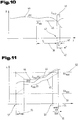
- Fig. 11 shows a further embodiment of the welding method according to the invention using the resistor R (t) 44 as a control variable for monitoring the welding process.
- Fig. 11 is a graph of the time course of the resistance R (t) 44 (corresponding to an average value for the second time interval 102) and the time-varying upper or lower limit, ie the minimum resistance Rmin (t) 45 and the maximum resistance Rmax (t) 46 (corresponding to the first time interval 101 according to FIG Fig. 3 ). It is now provided that in the control device 4, a predefined, absolute, minimum resistance RAmin 51 and an absolute maximum resistance RAmax 52 are stored. As from the diagram according to Fig.
- These threshold values 51, 52 ie the absolute maximum resistance RAmax 52 and the absolute minimum resistance RAmin 51, so to speak form a large tolerance window for the instantaneous resistance R (t) 44, which is set around this starting from a working point determined from a database. It can thus gross errors in the welding process by the control device 4 are detected.
- These absolute threshold values 51, 52 can be, for example also be used in the start phase of a welding process for monitoring, as this higher instabilities of the welding process can be expected.
- the difference between the time-varying upper and lower limit values ie the maximum resistance Rmax (t) 46 and the minimum resistance Rmin (t) 45, can be chosen to be substantially smaller than the difference of the corresponding time
- the difference between the time-varying limit values can make up a small fraction of the difference of the time-invariant threshold values 51, 52.
- control device 4 of the welding device 1 By the control device 4 of the welding device 1, a continuous comparison of the value of the resistance R (t) 44 (corresponding to the second time interval 102) with the minimum resistance RAmin 51 and the maximum resistance RAmax 52 takes place.
- a control signal is generated by the control device 4 at a point in time 53.
- this control signal is preferably provided that takes place by the control device 4, an automatic interruption of the welding process.
- a control time TKA 54 for the absolute limits is stored in the control device 4.
- the control device 4 After exceeding the maximum resistance RAmax 52 by the instantaneous resistance R (t) 44 at the time 53, the control device 4 starts measuring an observation time TBA 55 that lasts as long as the instantaneous resistance R (t) 44 above the maximum resistance RAmax is 52 or below the minimum resistance RAmin 51. The resolution or generation of a control signal by the control device 4 takes place when this observation time TBA 55 is longer than the predefined control time TKA 54.
- a start interval TS 56 starting from a start time 57 of the welding process is provided that only the absolute limits of the minimum resistance RAmin 51 and the maximum resistance RAmax 52 or the threshold values 51, 52 are used for monitoring the welding process by the control device 4. Only after the start interval TS 56 is the control device 4 for monitoring with the narrower, upper or lower limits 104 and 105, ie with the minimum resistance Rmin (t) 45 and with the maximum resistance Rmax (t) 46 transitioned , Alternatively, it is also possible that for the duration of the start interval TS 56, a continuously narrowing tolerance range for the upper and lower limits of the resistor R (t) 44 in the monitoring of the welding process by the control device 4 is used (dash-dotted lines drawn).
- a value of the order of 10 ms is used as the value for the control time TKA 54, while a range of 200 ms to 950 ms proves to be advantageous as the value for the duration of the start interval TS 56.
- the frequency H (t) 37 and the period of short-circuit occurrence TP 43 and the instantaneous value of the resistance R (t) 44 have been used as control quantities.
- control quantities such as the power of the arc in the context of the invention.
- control device 4 If it comes to exceeding the upper limit or below the lower limit value 104, 105 by the current value of the control variable, the control device 4 generates a control signal, as a result of which the welding process is interrupted or a status message about states of different components of the welding system can be generated.
- the threshold for the threshold value 51, 52 may be taken from the last weld or for the threshold values 51, 52 to be calculated from or stored in a database.
- the stored parameters 100 of the welding voltage and the welding current can be stored, and an average value of the resistance or the power to be used as the control variable or parameter 100 over the time intervals 101 and 102.
- a resistance or power is calculated and this stored as a parameter 100 for the time intervals 101 and 102 and over the period of time intervals 101 and 102 then the average is formed.
- a conversion of two welding parameters to a characteristic 100 for forming the average values can be carried out.
- a control time 54 or an observation time 55 is not started, but a counter is started which is counted up or down as long as the average value exceeds or falls below the limit value 104 or 105, the control signal then being generated when a specific counter reading is reached. After that it is possible that the counter will be reset. It is also possible that several meter readings are stored as limits, so ever after counter reading different control signals are emitted.
- the control apparatus 4 In order to allow the user to carry out all customary possibilities with the welding apparatus 1, it is possible for the control apparatus 4, during a change of the operating point, in particular a job change by the user, during the welding process to treat this as a restart of the welding process or over a defined period of time the parameters ignored. Thus it is prevented that by a corresponding change by the user an exceeding or falling below the limit values 104, 105 is effective immediately, but only when there is again a stable welding process.
- control device 4 by an external signal, the following characteristics over a predefined period of time or over the time of concern of the external signal or up to another external signal fades out and thus these parameters 100 not for the evaluation of the average values be used.
- This is advantageous in that automated welds often change the position of the welding torch, resulting in other parameters. This occurs, for example, when going from a horizontal weld into a vertical weld.
- the robot axes to be monitored by the control device 4 in the case of robot welding, whereupon the control device 4 calculates whether an average value monitoring of the welding process, ie this described control method, makes sense or can be carried out.
- the limiting values 104, 105 for the first average value of the first time interval 101 in the short-arc welding method 6%, in the pulse welding method 2.5% and in the spray-arc welding method 2.0% are increased or reduced by the control device 4.
- the duration of the first time interval 101 can be between 0.3 sec. And 1.0 sec., In particular 0.5 sec., While the duration of the second time interval 102 is between 0.05 sec. And 0.3 sec., In particular 0.1 sec., Is.
- the respective temporal position of the time interval 101, 102 the last determined value of the control variable immediately preceding chosen.
- a temporally invariable, lower threshold value 51 and a timewise, upper threshold value 52 for the control variable can be defined, the difference between the time-varying, upper limit value 104 and the time-varying lower limit value 105 being smaller, in particular is equal to a fraction of the difference between the temporally fixed upper threshold 52 and the temporally fixed lower threshold 51.
- the temporally invariable, lower threshold value 51 and the temporally unchangeable, upper threshold value 52 can be used and subsequently the time-varying, lower Limit 105 and the time-varying, upper limit 104 are used.
- the threshold for the threshold 51, 52 can be calculated from a database or stored in a database.
- the limit for the threshold value 51, 52 from the last weld can be used.
- the resistance R (t) 44 or the power is determined by averaging over at least one period TP 43 of the periodic voltage curve of the welding voltage U (t) 30 and / or the periodic current profile of the welding current I (t) 29 is calculated.
- a temporal sequence of period lengths TP 43 can be determined, the sequence of period lengths TP 43 is used as the control variable.
- the welding process is interrupted by the control device as a function of the control signal and / or a status message of states of the welding process, such as the wire feed, the state of the welding torch or the workpiece quality, is generated.
- a control of the feed device for changing a feed rate Vd of the welding wire 11 are triggered or can be triggered by the control signal driving a cooling device 18 for changing the cooling power for a welding torch 9 of the welding device 1.
- control device when a change in the operating point, in particular a job change by the user, treated as a restart of the welding process or ignored over a defined period of time, the parameters.
- the following parameters are masked by the control device by an external signal over a predefined period of time or over the time of application of the external signal or up to a further external signal and these parameters are not used for the evaluation of the average values 106, 107 become.
- the robot axes are monitored by the control device during a robot welding, whereupon the control device calculates whether an average value monitoring of the welding process is meaningful or should be carried out.
- the first time interval 101 is a duration between 0.3 and 1.0 seconds, in particular 0.5 seconds
- the second time interval 102 has a duration between 0.05 and 0.3 seconds, in particular 0, 1 second.
- control device may also be expedient for the control device to calculate the upper and lower limit values 104, 105 as a function of further welding parameters set by the user, in particular of the material to be welded, the type of welding process, such as short arc welding process, pulse welding process or spray arc Welding process occurs.
- control device preferably increases the limit values 104, 105 by 6% in the short-arc welding method by 6%, in the pulse welding method by 2.5% and in the spray-arc welding method by 2.0% . be reduced
Landscapes
- Engineering & Computer Science (AREA)
- Physics & Mathematics (AREA)
- Plasma & Fusion (AREA)
- Mechanical Engineering (AREA)
- Arc Welding Control (AREA)
Applications Claiming Priority (2)
| Application Number | Priority Date | Filing Date | Title |
|---|---|---|---|
| AT0150906A AT504197B1 (de) | 2006-09-08 | 2006-09-08 | Schweissverfahren zur durchführung eines schweissprozesses |
| PCT/AT2007/000419 WO2008028209A1 (de) | 2006-09-08 | 2007-09-03 | SCHWEIßVERFAHREN ZUR DURCHFÜHRUNG EINES SCHWEIßPROZESS |
Publications (2)
| Publication Number | Publication Date |
|---|---|
| EP2061620A1 EP2061620A1 (de) | 2009-05-27 |
| EP2061620B1 true EP2061620B1 (de) | 2018-02-21 |
Family
ID=38776299
Family Applications (1)
| Application Number | Title | Priority Date | Filing Date |
|---|---|---|---|
| EP07800164.1A Active EP2061620B1 (de) | 2006-09-08 | 2007-09-03 | SCHWEIßVERFAHREN ZUR DURCHFÜHRUNG EINES SCHWEIßPROZESSES |
Country Status (8)
| Country | Link |
|---|---|
| US (1) | US8389897B2 (enExample) |
| EP (1) | EP2061620B1 (enExample) |
| JP (1) | JP2010502446A (enExample) |
| CN (1) | CN101616768B (enExample) |
| AT (1) | AT504197B1 (enExample) |
| BR (1) | BRPI0716634B1 (enExample) |
| RU (1) | RU2431552C2 (enExample) |
| WO (1) | WO2008028209A1 (enExample) |
Families Citing this family (92)
| Publication number | Priority date | Publication date | Assignee | Title |
|---|---|---|---|---|
| US10994358B2 (en) | 2006-12-20 | 2021-05-04 | Lincoln Global, Inc. | System and method for creating or modifying a welding sequence based on non-real world weld data |
| US9104195B2 (en) | 2006-12-20 | 2015-08-11 | Lincoln Global, Inc. | Welding job sequencer |
| US9937577B2 (en) | 2006-12-20 | 2018-04-10 | Lincoln Global, Inc. | System for a welding sequencer |
| US9318026B2 (en) | 2008-08-21 | 2016-04-19 | Lincoln Global, Inc. | Systems and methods providing an enhanced user experience in a real-time simulated virtual reality welding environment |
| US9196169B2 (en) | 2008-08-21 | 2015-11-24 | Lincoln Global, Inc. | Importing and analyzing external data using a virtual reality welding system |
| US9330575B2 (en) | 2008-08-21 | 2016-05-03 | Lincoln Global, Inc. | Tablet-based welding simulator |
| US8851896B2 (en) | 2008-08-21 | 2014-10-07 | Lincoln Global, Inc. | Virtual reality GTAW and pipe welding simulator and setup |
| US9280913B2 (en) | 2009-07-10 | 2016-03-08 | Lincoln Global, Inc. | Systems and methods providing enhanced education and training in a virtual reality environment |
| US9483959B2 (en) | 2008-08-21 | 2016-11-01 | Lincoln Global, Inc. | Welding simulator |
| US8274013B2 (en) | 2009-03-09 | 2012-09-25 | Lincoln Global, Inc. | System for tracking and analyzing welding activity |
| US10035209B2 (en) * | 2009-03-18 | 2018-07-31 | Lincoln Global, Inc. | Adaptive GMAW short circuit frequency control |
| US9230449B2 (en) | 2009-07-08 | 2016-01-05 | Lincoln Global, Inc. | Welding training system |
| US9773429B2 (en) | 2009-07-08 | 2017-09-26 | Lincoln Global, Inc. | System and method for manual welder training |
| US9221117B2 (en) | 2009-07-08 | 2015-12-29 | Lincoln Global, Inc. | System for characterizing manual welding operations |
| EP2272615B1 (de) * | 2009-07-10 | 2016-08-31 | Ewm Ag | Konditionierung einer abschmelzenden Elektrode für das Lichtbogenschweissen oder Lichtbogenlöten unter Schutzgas |
| US9011154B2 (en) | 2009-07-10 | 2015-04-21 | Lincoln Global, Inc. | Virtual welding system |
| US10748447B2 (en) | 2013-05-24 | 2020-08-18 | Lincoln Global, Inc. | Systems and methods providing a computerized eyewear device to aid in welding |
| US8569655B2 (en) | 2009-10-13 | 2013-10-29 | Lincoln Global, Inc. | Welding helmet with integral user interface |
| US9468988B2 (en) | 2009-11-13 | 2016-10-18 | Lincoln Global, Inc. | Systems, methods, and apparatuses for monitoring weld quality |
| US8569646B2 (en) | 2009-11-13 | 2013-10-29 | Lincoln Global, Inc. | Systems, methods, and apparatuses for monitoring weld quality |
| US20110155711A1 (en) * | 2009-12-31 | 2011-06-30 | Thomas Edward Doyle | Adaptive control of arc welding parameters |
| KR101038569B1 (ko) * | 2010-07-05 | 2011-06-02 | 주식회사 유디엠텍 | 용접 모니터링 시스템 및 그 방법 |
| US10766089B2 (en) | 2010-07-14 | 2020-09-08 | Illinois Tool Works | Heat input control for welding systems |
| JP5808947B2 (ja) * | 2011-05-23 | 2015-11-10 | 株式会社ダイヘン | 消耗電極アーク溶接のくびれ検出制御方法 |
| JP2014524840A (ja) * | 2011-07-08 | 2014-09-25 | エイナヴ,オメル | 溶接中の手動シーム追跡システム及び方法並びに溶接支援システム |
| US20160093233A1 (en) | 2012-07-06 | 2016-03-31 | Lincoln Global, Inc. | System for characterizing manual welding operations on pipe and other curved structures |
| US9767712B2 (en) | 2012-07-10 | 2017-09-19 | Lincoln Global, Inc. | Virtual reality pipe welding simulator and setup |
| US9387550B2 (en) | 2012-09-14 | 2016-07-12 | Illinois Tool Works Inc. | Waveform compensation systems and methods for secondary weld component response |
| US10040143B2 (en) | 2012-12-12 | 2018-08-07 | Illinois Tool Works Inc. | Dabbing pulsed welding system and method |
| US10906114B2 (en) | 2012-12-21 | 2021-02-02 | Illinois Tool Works Inc. | System for arc welding with enhanced metal deposition |
| FI124470B (en) * | 2013-01-29 | 2014-09-15 | Kemppi Oy | IMPROVED CONTROL UNIT AND METHOD FOR WELDING DEVICE |
| US9506958B2 (en) | 2013-01-31 | 2016-11-29 | Illinois Tool Works Inc. | Waveform compensation systems and methods for secondary weld component response |
| US9950383B2 (en) | 2013-02-05 | 2018-04-24 | Illinois Tool Works Inc. | Welding wire preheating system and method |
| US10835983B2 (en) | 2013-03-14 | 2020-11-17 | Illinois Tool Works Inc. | Electrode negative pulse welding system and method |
| CN111007812A (zh) * | 2013-03-14 | 2020-04-14 | 林肯环球股份有限公司 | 接收或使用来自针对焊接序列的外部源的数据的系统和方法 |
| US9808879B2 (en) | 2013-04-12 | 2017-11-07 | Isawe, Llc | Welding diagnostic device for identifying metal transfer modes during a welding process and a method of identifying metal transfer modes of a welding process |
| AT513828B1 (de) * | 2013-04-22 | 2014-08-15 | Fronius Int Gmbh | Verfahren und eine Vorrichtung zum Simulieren eines Elektrodenschweißverfahrens |
| US10930174B2 (en) | 2013-05-24 | 2021-02-23 | Lincoln Global, Inc. | Systems and methods providing a computerized eyewear device to aid in welding |
| US11045891B2 (en) | 2013-06-13 | 2021-06-29 | Illinois Tool Works Inc. | Systems and methods for anomalous cathode event control |
| US20150072323A1 (en) | 2013-09-11 | 2015-03-12 | Lincoln Global, Inc. | Learning management system for a real-time simulated virtual reality welding training environment |
| US10828728B2 (en) | 2013-09-26 | 2020-11-10 | Illinois Tool Works Inc. | Hotwire deposition material processing system and method |
| US10083627B2 (en) | 2013-11-05 | 2018-09-25 | Lincoln Global, Inc. | Virtual reality and real welding training system and method |
| US9836987B2 (en) | 2014-02-14 | 2017-12-05 | Lincoln Global, Inc. | Virtual reality pipe welding simulator and setup |
| EP3111440A1 (en) | 2014-06-02 | 2017-01-04 | Lincoln Global, Inc. | System and method for manual welder training |
| US11154946B2 (en) | 2014-06-30 | 2021-10-26 | Illinois Tool Works Inc. | Systems and methods for the control of welding parameters |
| BR202014017803U2 (pt) * | 2014-07-18 | 2015-02-10 | Sumig Solucoes Para Solda E Corte Ltda | Disposição introduzida em sinalização através de sistema vibratório em equipamento de medição e análise de parâmetros de soldagem em tempo real |
| US11198189B2 (en) | 2014-09-17 | 2021-12-14 | Illinois Tool Works Inc. | Electrode negative pulse welding system and method |
| US10239147B2 (en) * | 2014-10-16 | 2019-03-26 | Illinois Tool Works Inc. | Sensor-based power controls for a welding system |
| US11478870B2 (en) | 2014-11-26 | 2022-10-25 | Illinois Tool Works Inc. | Dabbing pulsed welding system and method |
| US10189106B2 (en) | 2014-12-11 | 2019-01-29 | Illinois Tool Works Inc. | Reduced energy welding system and method |
| US11370050B2 (en) | 2015-03-31 | 2022-06-28 | Illinois Tool Works Inc. | Controlled short circuit welding system and method |
| JP6636284B2 (ja) * | 2015-08-21 | 2020-01-29 | 株式会社ダイヘン | アーク溶接品質判定システム |
| EP3345710B1 (en) * | 2015-09-03 | 2024-05-15 | Panasonic Intellectual Property Management Co., Ltd. | Arc welding method and arc welding device |
| US11285559B2 (en) | 2015-11-30 | 2022-03-29 | Illinois Tool Works Inc. | Welding system and method for shielded welding wires |
| US10610946B2 (en) | 2015-12-07 | 2020-04-07 | Illinois Tool Works, Inc. | Systems and methods for automated root pass welding |
| US12194579B2 (en) | 2015-12-10 | 2025-01-14 | Illinois Tool Works Inc. | Systems, methods, and apparatus to preheat welding wire |
| US10675699B2 (en) | 2015-12-10 | 2020-06-09 | Illinois Tool Works Inc. | Systems, methods, and apparatus to preheat welding wire |
| US10603735B2 (en) | 2016-08-16 | 2020-03-31 | Illinois Tool Works Inc. | Welding power supplies, wire feeders, and systems to compensate a weld voltage via communications over a weld circuit |
| US10773331B2 (en) | 2016-08-16 | 2020-09-15 | Illinois Tool Works Inc. | Welding power supplies, wire feeders, and systems to compensate a weld voltage via communications over a weld circuit |
| EP3319066A1 (en) | 2016-11-04 | 2018-05-09 | Lincoln Global, Inc. | Magnetic frequency selection for electromagnetic position tracking |
| US10913125B2 (en) | 2016-11-07 | 2021-02-09 | Lincoln Global, Inc. | Welding system providing visual and audio cues to a welding helmet with a display |
| US20180130226A1 (en) | 2016-11-07 | 2018-05-10 | Lincoln Global, Inc. | System and method for calibrating a welding trainer |
| US11027355B2 (en) * | 2017-03-09 | 2021-06-08 | Illinois Tool Works | Welding power supplies, wire feeders, and systems to measure a weld circuit resistance via communications over the weld circuit |
| US11660695B2 (en) | 2017-03-09 | 2023-05-30 | Illinois Tool Works Inc. | Welding power supplies, wire feeders, and systems to measure a weld cable voltage drop |
| US10766092B2 (en) | 2017-04-18 | 2020-09-08 | Illinois Tool Works Inc. | Systems, methods, and apparatus to provide preheat voltage feedback loss protection |
| US10870164B2 (en) | 2017-05-16 | 2020-12-22 | Illinois Tool Works Inc. | Systems, methods, and apparatus to preheat welding wire |
| US10997872B2 (en) | 2017-06-01 | 2021-05-04 | Lincoln Global, Inc. | Spring-loaded tip assembly to support simulated shielded metal arc welding |
| EP3634682B1 (en) | 2017-06-09 | 2023-08-23 | Illinois Tool Works, Inc. | Contact tip with screw threads with longitudinal slots for gas flow, and a head to enable unthreading ; welding torch with such contact tip |
| WO2018227196A1 (en) | 2017-06-09 | 2018-12-13 | Illinois Tool Works Inc. | Welding torch, with two contact tips and a plurality of liquid cooling assemblies for conducting currents to the contact tips |
| EP3634683B1 (en) | 2017-06-09 | 2022-03-23 | Illinois Tool Works, Inc. | Welding assembly for a welding torch, with two contact tips and a cooling body to cool and conduct current |
| US11524354B2 (en) | 2017-06-09 | 2022-12-13 | Illinois Tool Works Inc. | Systems, methods, and apparatus to control weld current in a preheating system |
| CA3066619C (en) | 2017-06-09 | 2022-07-19 | Illinois Tool Works Inc. | Welding torch with a first contact tip to preheat welding wire and a second contact tip |
| US11020813B2 (en) | 2017-09-13 | 2021-06-01 | Illinois Tool Works Inc. | Systems, methods, and apparatus to reduce cast in a welding wire |
| US11557223B2 (en) | 2018-04-19 | 2023-01-17 | Lincoln Global, Inc. | Modular and reconfigurable chassis for simulated welding training |
| US11475792B2 (en) | 2018-04-19 | 2022-10-18 | Lincoln Global, Inc. | Welding simulator with dual-user configuration |
| WO2020047438A1 (en) | 2018-08-31 | 2020-03-05 | Illinois Tool Works Inc. | Submerged arc welding systems and submerged arc welding torches to resistively preheat electrode wire |
| US11014185B2 (en) | 2018-09-27 | 2021-05-25 | Illinois Tool Works Inc. | Systems, methods, and apparatus for control of wire preheating in welding-type systems |
| EP3898055A2 (en) | 2018-12-19 | 2021-10-27 | Illinois Tool Works, Inc. | Contact tip, wire preheating assembly, contact tip assembly and consumable electrode-fed welding type system |
| US11969835B2 (en) | 2019-03-26 | 2024-04-30 | Lincoln Global, Inc. | Tip saver for a welding system |
| US11623292B2 (en) * | 2019-03-29 | 2023-04-11 | Lincoln Global, Inc. | Real time resistance monitoring of an arc welding circuit |
| EP3722039A1 (de) * | 2019-04-10 | 2020-10-14 | FRONIUS INTERNATIONAL GmbH | Schweissverfahren und -anordnung mit messwertsynchronisation |
| US12103121B2 (en) | 2019-04-30 | 2024-10-01 | Illinois Tool Works Inc. | Methods and apparatus to control welding power and preheating power |
| US11911857B2 (en) * | 2019-06-28 | 2024-02-27 | Illinois Tool Works Inc. | Apparatus and systems to determine voltage measurements in welding-type applications |
| US12337424B2 (en) * | 2019-10-02 | 2025-06-24 | Illinois Tool Works Inc. | Systems and methods for automatic control of welding parameter output ranges |
| US20210129252A1 (en) * | 2019-11-01 | 2021-05-06 | Illinois Tool Works Inc. | Systems and methods to control welding-type power supplies using ac waveforms and/or dc pulse waveforms |
| US12390873B2 (en) * | 2019-11-01 | 2025-08-19 | Illinois Tool Works Inc. | Systems and methods to control welding-type power supplies using AC waveforms and/or DC pulse waveforms |
| EP3822014A1 (de) * | 2019-11-18 | 2021-05-19 | FRONIUS INTERNATIONAL GmbH | Verfahren zum abtasten der oberfläche metallischer werkstücke |
| US11772182B2 (en) | 2019-12-20 | 2023-10-03 | Illinois Tool Works Inc. | Systems and methods for gas control during welding wire pretreatments |
| CN115167281B (zh) * | 2022-06-20 | 2025-03-18 | 南京云岗智能科技有限公司 | 直流氩弧焊工艺执行告警方法、装置、电子设备及介质 |
| CN115255576B (zh) * | 2022-07-27 | 2024-06-04 | 深圳市爱达思技术有限公司 | 焊接工作点设置方法、装置、设备及存储介质 |
| CN118848167B (zh) * | 2024-09-29 | 2025-01-24 | 山东鲁岳电气有限公司 | 一种钢厂电磁吸盘外壳焊接装置及其焊接方法 |
| CN119625510A (zh) * | 2025-02-13 | 2025-03-14 | 浙江机电职业技术大学 | 一种焊接电弧图像采集处理系统及方法 |
Family Cites Families (26)
| Publication number | Priority date | Publication date | Assignee | Title |
|---|---|---|---|---|
| US3555239A (en) * | 1966-11-16 | 1971-01-12 | William J Kerth | Welding machine with digital pulse control |
| US5061841A (en) * | 1982-10-22 | 1991-10-29 | The Ohio State University | Apparatus and methods for controlling a welding process |
| US4532404A (en) * | 1983-02-01 | 1985-07-30 | Canadian Patents And Development Limited | Real time control system and process for controlling predetermined operating characteristics of a welding mechanism |
| EP0248654B1 (en) | 1986-06-04 | 1993-10-13 | Welding Industries Of Australia Proprietary Limited | Pulsed arc welding |
| SU1704985A1 (ru) | 1990-04-13 | 1992-01-15 | Всесоюзный научно-исследовательский, проектно-конструкторский и технологический институт электросварочного оборудования | Способ управлени тиристорами последовательного инвертора источника тока дл контактной сварки |
| KR100219813B1 (ko) * | 1990-04-17 | 1999-09-01 | 니시마쓰 다이조 | Mag 아아크 용접 방법 및 용접장치 |
| DE4203190C1 (en) | 1992-02-05 | 1993-05-13 | Fraunhofer-Gesellschaft Zur Foerderung Der Angewandten Forschung Ev, 8000 Muenchen, De | Regulation and quality assessing of welding esp. spot welding - has ultrasonic detecting probe attached to welding electrode to record noise emission level at weld location |
| US5278390A (en) * | 1993-03-18 | 1994-01-11 | The Lincoln Electric Company | System and method for controlling a welding process for an arc welder |
| US5571431A (en) * | 1995-03-31 | 1996-11-05 | Mk Products, Inc. | Method and apparatus for controlling and simultaneously displaying arc welding process parameters |
| CN1063119C (zh) * | 1995-09-19 | 2001-03-14 | 株式会社安川电机 | 焊接条件自动设定装置 |
| FR2756036B1 (fr) * | 1996-11-20 | 1999-01-08 | Dehon Sa Anciens Etablissement | Procede pour re-eprouver un emballage rempli d'un fluide actif et d'un propulseur et appareillage pour la mise en oeuvre du procede |
| US5756967A (en) * | 1997-04-09 | 1998-05-26 | The United States Of America As Represented By The Secretary Of Commerce | Sensing ARC welding process characteristics for welding process control |
| RU2120843C1 (ru) | 1997-07-31 | 1998-10-27 | Производственное объединение "Юргинский машиностроительный завод" | Способ электродуговой сварки |
| JP3852635B2 (ja) | 1997-08-08 | 2006-12-06 | 株式会社安川電機 | アーク溶接モニタ装置 |
| US6107601A (en) * | 1997-10-01 | 2000-08-22 | Matsushita Electric Industrial Co., Ltd. | Apparatus and method for controlling an arc welding robot |
| AT411880B (de) * | 1998-01-13 | 2004-07-26 | Fronius Int Gmbh | Steuervorrichtung für ein schweissgerät |
| JP3813732B2 (ja) * | 1998-04-07 | 2006-08-23 | 株式会社豊田自動織機 | パルスアーク溶接の制御方法及び装置 |
| AT409239B (de) * | 1998-05-13 | 2002-06-25 | Fronius Schweissmasch | Verfahren zum steuern eines schweissgerätes und steuervorrichtung hierfür |
| JP2001162372A (ja) | 1999-12-06 | 2001-06-19 | Hitachi Ltd | パルスアーク溶接装置 |
| US6365874B1 (en) | 2000-05-22 | 2002-04-02 | Lincoln Global, Inc. | Power supply for electric arc welding |
| AT411878B (de) * | 2000-10-17 | 2004-07-26 | Fronius Schweissmasch Prod | Verfahren zum steuern und/oder regeln eines schweissprozesses |
| US6498321B1 (en) | 2001-04-09 | 2002-12-24 | Lincoln Global, Inc. | System and method for controlling an electric arc welder |
| US6472634B1 (en) | 2001-04-17 | 2002-10-29 | Lincoln Global, Inc. | Electric arc welding system |
| US6977357B2 (en) * | 2003-07-09 | 2005-12-20 | Lincoln Global, Inc. | Welding wire positioning system |
| CN102009245A (zh) * | 2003-10-23 | 2011-04-13 | 弗罗纽斯国际有限公司 | 控制焊接工艺的方法以及实施焊接工艺的焊接设备 |
| JP4857534B2 (ja) * | 2004-07-13 | 2012-01-18 | パナソニック株式会社 | アーク溶接ロボット |
-
2006
- 2006-09-08 AT AT0150906A patent/AT504197B1/de not_active IP Right Cessation
-
2007
- 2007-09-03 BR BRPI0716634A patent/BRPI0716634B1/pt not_active IP Right Cessation
- 2007-09-03 RU RU2009113035/02A patent/RU2431552C2/ru not_active IP Right Cessation
- 2007-09-03 JP JP2009526985A patent/JP2010502446A/ja active Pending
- 2007-09-03 CN CN2007800376450A patent/CN101616768B/zh not_active Expired - Fee Related
- 2007-09-03 WO PCT/AT2007/000419 patent/WO2008028209A1/de not_active Ceased
- 2007-09-03 US US12/310,873 patent/US8389897B2/en not_active Expired - Fee Related
- 2007-09-03 EP EP07800164.1A patent/EP2061620B1/de active Active
Also Published As
| Publication number | Publication date |
|---|---|
| US20100133250A1 (en) | 2010-06-03 |
| US8389897B2 (en) | 2013-03-05 |
| BRPI0716634A2 (pt) | 2013-09-24 |
| EP2061620A1 (de) | 2009-05-27 |
| WO2008028209A1 (de) | 2008-03-13 |
| BRPI0716634B1 (pt) | 2016-08-09 |
| JP2010502446A (ja) | 2010-01-28 |
| RU2431552C2 (ru) | 2011-10-20 |
| AT504197A1 (de) | 2008-03-15 |
| RU2009113035A (ru) | 2010-10-20 |
| CN101616768B (zh) | 2011-10-26 |
| CN101616768A (zh) | 2009-12-30 |
| AT504197B1 (de) | 2010-01-15 |
Similar Documents
| Publication | Publication Date | Title |
|---|---|---|
| EP2061620B1 (de) | SCHWEIßVERFAHREN ZUR DURCHFÜHRUNG EINES SCHWEIßPROZESSES | |
| AT410641B (de) | Verfahren zum fortlaufenden regeln bzw. nachführen einer position eines schweissbrenners bzw. eines schweisskopfes | |
| EP1412125B1 (de) | Verfahren zum kurzzeit-lichtbogenschweissen sowie kurzzeit-lichtbogenschweisssystem, um hochfrequente störungen zu erkennen | |
| AT501995B1 (de) | Kalt-metall-transfer-schweissverfahren sowie schweissanlage | |
| AT501489B1 (de) | Verfahren zum steuern und/oder regeln eines schweissgerätes und schweissgerät | |
| EP1677941B1 (de) | Verfahren zum steuern und/oder regeln eines schweissprozesses | |
| DE3718624A1 (de) | Funkenerosionsmaschine | |
| EP2359974B1 (de) | Lichtbogen-Schweißverfahren und Schweißstromquelle zur Durchführung des Verfahrens | |
| DE2921658A1 (de) | Schweissgeraet | |
| DE102006050297B4 (de) | Impulslichtbogenprozess | |
| DE69607273T2 (de) | Verfahren und Vorrichtung zum Schweissen in einer Fuge mit verbesserten Lichtbogenspannungsdetektierung und Steuerung | |
| EP0095056A1 (de) | Verfahren und Einrichtung zum Metallichtbogenschweissen | |
| DE112013001259T5 (de) | Vorrichtung und Verfahren zum Starten eines Lichtbogenschweissprozesses mit pulsierendem Draht vor der Initiierung der Lichtbogenbildung | |
| EP3755490B1 (de) | Lichtbogenschweissverfahren mit einem abschmelzenden schweissdraht | |
| EP4054784B1 (de) | Verfahren und vorrichtung zum schweissen einer schweissnaht | |
| EP4204176B1 (de) | Verfahren und schweissvorrichtung mit detektion von elektrischen kontakten bei einem schweissprozess | |
| EP4153376B1 (de) | Verfahren und vorrichtung zur überwachung einer nichtabschmelzenden schweisselektrode einer automatischen lichtbogenschweissvorrichtung | |
| DE102007004177A1 (de) | Sanfter Kurzschlusseintritt | |
| EP4017669B1 (de) | Verfahren zur ermittlung des verschleisses eines kontaktrohres während eines robotergestützten schweissverfahrens | |
| AT409468B (de) | Verfahren zum zünden eines lichtbogens zwischen einem werkstück und einer abschmelzenden elektrode | |
| EP4652008A1 (de) | Regelung intervallfügeverfahren | |
| DE2342710C3 (de) | Verfahren und Stromversorgungsanordnung zum Kurzlichtbogen-Schweißen | |
| EP4079436A1 (de) | Verfahren zum steuern oder regeln der vorschubgeschwindigkeit eines drahts aus abschmelzendem material bei einem laserlöt- oder laserschweissverfahren sowie laserlöt- oder laserschweissvorrichtung zur durchführung eines solchen verfahrens | |
| DE3807103A1 (de) | Verfahren zum zuenden beim mig-mag-schweissen | |
| DD277029A1 (de) | Verfahren zur dynamischen regelung des punkt-, buckel- oder rollennahtschweissprozesses |
Legal Events
| Date | Code | Title | Description |
|---|---|---|---|
| PUAI | Public reference made under article 153(3) epc to a published international application that has entered the european phase |
Free format text: ORIGINAL CODE: 0009012 |
|
| 17P | Request for examination filed |
Effective date: 20090403 |
|
| AK | Designated contracting states |
Kind code of ref document: A1 Designated state(s): AT BE BG CH CY CZ DE DK EE ES FI FR GB GR HU IE IS IT LI LT LU LV MC MT NL PL PT RO SE SI SK TR |
|
| AX | Request for extension of the european patent |
Extension state: AL BA HR MK RS |
|
| DAX | Request for extension of the european patent (deleted) | ||
| GRAP | Despatch of communication of intention to grant a patent |
Free format text: ORIGINAL CODE: EPIDOSNIGR1 |
|
| INTG | Intention to grant announced |
Effective date: 20170418 |
|
| GRAJ | Information related to disapproval of communication of intention to grant by the applicant or resumption of examination proceedings by the epo deleted |
Free format text: ORIGINAL CODE: EPIDOSDIGR1 |
|
| RIN1 | Information on inventor provided before grant (corrected) |
Inventor name: TRAUNER, GERNOT Inventor name: SARDY, BANK |
|
| INTC | Intention to grant announced (deleted) | ||
| RAP1 | Party data changed (applicant data changed or rights of an application transferred) |
Owner name: FRONIUS INTERNATIONAL GMBH |
|
| GRAP | Despatch of communication of intention to grant a patent |
Free format text: ORIGINAL CODE: EPIDOSNIGR1 |
|
| INTG | Intention to grant announced |
Effective date: 20170919 |
|
| GRAS | Grant fee paid |
Free format text: ORIGINAL CODE: EPIDOSNIGR3 |
|
| GRAA | (expected) grant |
Free format text: ORIGINAL CODE: 0009210 |
|
| AK | Designated contracting states |
Kind code of ref document: B1 Designated state(s): AT BE BG CH CY CZ DE DK EE ES FI FR GB GR HU IE IS IT LI LT LU LV MC MT NL PL PT RO SE SI SK TR |
|
| REG | Reference to a national code |
Ref country code: GB Ref legal event code: FG4D Free format text: NOT ENGLISH |
|
| REG | Reference to a national code |
Ref country code: CH Ref legal event code: EP |
|
| REG | Reference to a national code |
Ref country code: AT Ref legal event code: REF Ref document number: 971167 Country of ref document: AT Kind code of ref document: T Effective date: 20180315 |
|
| REG | Reference to a national code |
Ref country code: IE Ref legal event code: FG4D Free format text: LANGUAGE OF EP DOCUMENT: GERMAN |
|
| REG | Reference to a national code |
Ref country code: DE Ref legal event code: R096 Ref document number: 502007016069 Country of ref document: DE |
|
| REG | Reference to a national code |
Ref country code: NL Ref legal event code: MP Effective date: 20180221 |
|
| REG | Reference to a national code |
Ref country code: LT Ref legal event code: MG4D |
|
| PG25 | Lapsed in a contracting state [announced via postgrant information from national office to epo] |
Ref country code: ES Free format text: LAPSE BECAUSE OF FAILURE TO SUBMIT A TRANSLATION OF THE DESCRIPTION OR TO PAY THE FEE WITHIN THE PRESCRIBED TIME-LIMIT Effective date: 20180221 Ref country code: NL Free format text: LAPSE BECAUSE OF FAILURE TO SUBMIT A TRANSLATION OF THE DESCRIPTION OR TO PAY THE FEE WITHIN THE PRESCRIBED TIME-LIMIT Effective date: 20180221 Ref country code: LT Free format text: LAPSE BECAUSE OF FAILURE TO SUBMIT A TRANSLATION OF THE DESCRIPTION OR TO PAY THE FEE WITHIN THE PRESCRIBED TIME-LIMIT Effective date: 20180221 Ref country code: CY Free format text: LAPSE BECAUSE OF FAILURE TO SUBMIT A TRANSLATION OF THE DESCRIPTION OR TO PAY THE FEE WITHIN THE PRESCRIBED TIME-LIMIT Effective date: 20180221 |
|
| PG25 | Lapsed in a contracting state [announced via postgrant information from national office to epo] |
Ref country code: LV Free format text: LAPSE BECAUSE OF FAILURE TO SUBMIT A TRANSLATION OF THE DESCRIPTION OR TO PAY THE FEE WITHIN THE PRESCRIBED TIME-LIMIT Effective date: 20180221 Ref country code: SE Free format text: LAPSE BECAUSE OF FAILURE TO SUBMIT A TRANSLATION OF THE DESCRIPTION OR TO PAY THE FEE WITHIN THE PRESCRIBED TIME-LIMIT Effective date: 20180221 Ref country code: GR Free format text: LAPSE BECAUSE OF FAILURE TO SUBMIT A TRANSLATION OF THE DESCRIPTION OR TO PAY THE FEE WITHIN THE PRESCRIBED TIME-LIMIT Effective date: 20180522 Ref country code: BG Free format text: LAPSE BECAUSE OF FAILURE TO SUBMIT A TRANSLATION OF THE DESCRIPTION OR TO PAY THE FEE WITHIN THE PRESCRIBED TIME-LIMIT Effective date: 20180521 |
|
| PG25 | Lapsed in a contracting state [announced via postgrant information from national office to epo] |
Ref country code: MT Free format text: LAPSE BECAUSE OF FAILURE TO SUBMIT A TRANSLATION OF THE DESCRIPTION OR TO PAY THE FEE WITHIN THE PRESCRIBED TIME-LIMIT Effective date: 20180221 |
|
| PG25 | Lapsed in a contracting state [announced via postgrant information from national office to epo] |
Ref country code: RO Free format text: LAPSE BECAUSE OF FAILURE TO SUBMIT A TRANSLATION OF THE DESCRIPTION OR TO PAY THE FEE WITHIN THE PRESCRIBED TIME-LIMIT Effective date: 20180221 Ref country code: IT Free format text: LAPSE BECAUSE OF FAILURE TO SUBMIT A TRANSLATION OF THE DESCRIPTION OR TO PAY THE FEE WITHIN THE PRESCRIBED TIME-LIMIT Effective date: 20180221 Ref country code: EE Free format text: LAPSE BECAUSE OF FAILURE TO SUBMIT A TRANSLATION OF THE DESCRIPTION OR TO PAY THE FEE WITHIN THE PRESCRIBED TIME-LIMIT Effective date: 20180221 Ref country code: PL Free format text: LAPSE BECAUSE OF FAILURE TO SUBMIT A TRANSLATION OF THE DESCRIPTION OR TO PAY THE FEE WITHIN THE PRESCRIBED TIME-LIMIT Effective date: 20180221 |
|
| REG | Reference to a national code |
Ref country code: DE Ref legal event code: R097 Ref document number: 502007016069 Country of ref document: DE |
|
| PG25 | Lapsed in a contracting state [announced via postgrant information from national office to epo] |
Ref country code: SK Free format text: LAPSE BECAUSE OF FAILURE TO SUBMIT A TRANSLATION OF THE DESCRIPTION OR TO PAY THE FEE WITHIN THE PRESCRIBED TIME-LIMIT Effective date: 20180221 Ref country code: CZ Free format text: LAPSE BECAUSE OF FAILURE TO SUBMIT A TRANSLATION OF THE DESCRIPTION OR TO PAY THE FEE WITHIN THE PRESCRIBED TIME-LIMIT Effective date: 20180221 Ref country code: DK Free format text: LAPSE BECAUSE OF FAILURE TO SUBMIT A TRANSLATION OF THE DESCRIPTION OR TO PAY THE FEE WITHIN THE PRESCRIBED TIME-LIMIT Effective date: 20180221 |
|
| PLBE | No opposition filed within time limit |
Free format text: ORIGINAL CODE: 0009261 |
|
| STAA | Information on the status of an ep patent application or granted ep patent |
Free format text: STATUS: NO OPPOSITION FILED WITHIN TIME LIMIT |
|
| 26N | No opposition filed |
Effective date: 20181122 |
|
| REG | Reference to a national code |
Ref country code: DE Ref legal event code: R082 Ref document number: 502007016069 Country of ref document: DE Representative=s name: ABP BURGER RECHTSANWALTSGESELLSCHAFT MBH, DE |
|
| PG25 | Lapsed in a contracting state [announced via postgrant information from national office to epo] |
Ref country code: SI Free format text: LAPSE BECAUSE OF FAILURE TO SUBMIT A TRANSLATION OF THE DESCRIPTION OR TO PAY THE FEE WITHIN THE PRESCRIBED TIME-LIMIT Effective date: 20180221 |
|
| PG25 | Lapsed in a contracting state [announced via postgrant information from national office to epo] |
Ref country code: MC Free format text: LAPSE BECAUSE OF FAILURE TO SUBMIT A TRANSLATION OF THE DESCRIPTION OR TO PAY THE FEE WITHIN THE PRESCRIBED TIME-LIMIT Effective date: 20180221 |
|
| REG | Reference to a national code |
Ref country code: CH Ref legal event code: PL |
|
| GBPC | Gb: european patent ceased through non-payment of renewal fee |
Effective date: 20180903 |
|
| REG | Reference to a national code |
Ref country code: BE Ref legal event code: MM Effective date: 20180930 |
|
| REG | Reference to a national code |
Ref country code: IE Ref legal event code: MM4A |
|
| PG25 | Lapsed in a contracting state [announced via postgrant information from national office to epo] |
Ref country code: LU Free format text: LAPSE BECAUSE OF NON-PAYMENT OF DUE FEES Effective date: 20180903 |
|
| PG25 | Lapsed in a contracting state [announced via postgrant information from national office to epo] |
Ref country code: IE Free format text: LAPSE BECAUSE OF NON-PAYMENT OF DUE FEES Effective date: 20180903 |
|
| PG25 | Lapsed in a contracting state [announced via postgrant information from national office to epo] |
Ref country code: CH Free format text: LAPSE BECAUSE OF NON-PAYMENT OF DUE FEES Effective date: 20180930 Ref country code: BE Free format text: LAPSE BECAUSE OF NON-PAYMENT OF DUE FEES Effective date: 20180930 Ref country code: LI Free format text: LAPSE BECAUSE OF NON-PAYMENT OF DUE FEES Effective date: 20180930 Ref country code: FR Free format text: LAPSE BECAUSE OF NON-PAYMENT OF DUE FEES Effective date: 20180930 |
|
| PG25 | Lapsed in a contracting state [announced via postgrant information from national office to epo] |
Ref country code: GB Free format text: LAPSE BECAUSE OF NON-PAYMENT OF DUE FEES Effective date: 20180903 |
|
| REG | Reference to a national code |
Ref country code: AT Ref legal event code: MM01 Ref document number: 971167 Country of ref document: AT Kind code of ref document: T Effective date: 20180903 |
|
| PG25 | Lapsed in a contracting state [announced via postgrant information from national office to epo] |
Ref country code: AT Free format text: LAPSE BECAUSE OF NON-PAYMENT OF DUE FEES Effective date: 20180903 |
|
| PG25 | Lapsed in a contracting state [announced via postgrant information from national office to epo] |
Ref country code: TR Free format text: LAPSE BECAUSE OF FAILURE TO SUBMIT A TRANSLATION OF THE DESCRIPTION OR TO PAY THE FEE WITHIN THE PRESCRIBED TIME-LIMIT Effective date: 20180221 |
|
| PG25 | Lapsed in a contracting state [announced via postgrant information from national office to epo] |
Ref country code: PT Free format text: LAPSE BECAUSE OF FAILURE TO SUBMIT A TRANSLATION OF THE DESCRIPTION OR TO PAY THE FEE WITHIN THE PRESCRIBED TIME-LIMIT Effective date: 20180221 Ref country code: HU Free format text: LAPSE BECAUSE OF FAILURE TO SUBMIT A TRANSLATION OF THE DESCRIPTION OR TO PAY THE FEE WITHIN THE PRESCRIBED TIME-LIMIT; INVALID AB INITIO Effective date: 20070903 |
|
| PG25 | Lapsed in a contracting state [announced via postgrant information from national office to epo] |
Ref country code: IS Free format text: LAPSE BECAUSE OF FAILURE TO SUBMIT A TRANSLATION OF THE DESCRIPTION OR TO PAY THE FEE WITHIN THE PRESCRIBED TIME-LIMIT Effective date: 20180621 |
|
| P01 | Opt-out of the competence of the unified patent court (upc) registered |
Effective date: 20230530 |
|
| PGFP | Annual fee paid to national office [announced via postgrant information from national office to epo] |
Ref country code: FI Payment date: 20230926 Year of fee payment: 17 |
|
| PG25 | Lapsed in a contracting state [announced via postgrant information from national office to epo] |
Ref country code: FI Free format text: LAPSE BECAUSE OF NON-PAYMENT OF DUE FEES Effective date: 20240903 |
|
| PGFP | Annual fee paid to national office [announced via postgrant information from national office to epo] |
Ref country code: DE Payment date: 20250926 Year of fee payment: 19 |