EP2060357B1 - Procédé de fabrication d'un corps en nid d'abeille - Google Patents
Procédé de fabrication d'un corps en nid d'abeille Download PDFInfo
- Publication number
- EP2060357B1 EP2060357B1 EP08021590.8A EP08021590A EP2060357B1 EP 2060357 B1 EP2060357 B1 EP 2060357B1 EP 08021590 A EP08021590 A EP 08021590A EP 2060357 B1 EP2060357 B1 EP 2060357B1
- Authority
- EP
- European Patent Office
- Prior art keywords
- adhesive
- layers
- layer
- drops
- nozzle
- Prior art date
- Legal status (The legal status is an assumption and is not a legal conclusion. Google has not performed a legal analysis and makes no representation as to the accuracy of the status listed.)
- Active
Links
- 238000004519 manufacturing process Methods 0.000 title description 10
- 239000000853 adhesive Substances 0.000 claims description 213
- 230000001070 adhesive effect Effects 0.000 claims description 210
- 238000000034 method Methods 0.000 claims description 86
- 229910000679 solder Inorganic materials 0.000 claims description 37
- 239000000463 material Substances 0.000 claims description 15
- 230000005284 excitation Effects 0.000 claims description 11
- 238000010438 heat treatment Methods 0.000 claims description 9
- 238000009835 boiling Methods 0.000 claims description 5
- 230000010355 oscillation Effects 0.000 claims description 5
- 238000007669 thermal treatment Methods 0.000 claims description 5
- 239000010410 layer Substances 0.000 description 177
- 241000264877 Hippospongia communis Species 0.000 description 58
- 238000007639 printing Methods 0.000 description 38
- 238000004804 winding Methods 0.000 description 17
- 238000005476 soldering Methods 0.000 description 16
- 239000002184 metal Substances 0.000 description 14
- 230000033001 locomotion Effects 0.000 description 10
- 239000000843 powder Substances 0.000 description 7
- 239000003795 chemical substances by application Substances 0.000 description 6
- 229920000914 Metallic fiber Polymers 0.000 description 5
- 239000011888 foil Substances 0.000 description 5
- 239000003292 glue Substances 0.000 description 5
- 239000002131 composite material Substances 0.000 description 4
- 239000002245 particle Substances 0.000 description 4
- 230000015572 biosynthetic process Effects 0.000 description 3
- 239000000919 ceramic Substances 0.000 description 3
- 238000010276 construction Methods 0.000 description 3
- 239000000835 fiber Substances 0.000 description 3
- 239000007788 liquid Substances 0.000 description 3
- MWUXSHHQAYIFBG-UHFFFAOYSA-N nitrogen oxide Inorganic materials O=[N] MWUXSHHQAYIFBG-UHFFFAOYSA-N 0.000 description 3
- 238000005219 brazing Methods 0.000 description 2
- 239000003054 catalyst Substances 0.000 description 2
- 230000000694 effects Effects 0.000 description 2
- 230000005686 electrostatic field Effects 0.000 description 2
- 239000002657 fibrous material Substances 0.000 description 2
- 239000007789 gas Substances 0.000 description 2
- 238000007641 inkjet printing Methods 0.000 description 2
- 239000000155 melt Substances 0.000 description 2
- 238000002844 melting Methods 0.000 description 2
- 230000008018 melting Effects 0.000 description 2
- 238000003860 storage Methods 0.000 description 2
- 239000000126 substance Substances 0.000 description 2
- 239000004820 Pressure-sensitive adhesive Substances 0.000 description 1
- 238000004026 adhesive bonding Methods 0.000 description 1
- 239000012790 adhesive layer Substances 0.000 description 1
- 229910045601 alloy Inorganic materials 0.000 description 1
- 239000000956 alloy Substances 0.000 description 1
- 238000000576 coating method Methods 0.000 description 1
- 230000001419 dependent effect Effects 0.000 description 1
- 238000011161 development Methods 0.000 description 1
- 230000018109 developmental process Effects 0.000 description 1
- 238000001914 filtration Methods 0.000 description 1
- 229930195733 hydrocarbon Natural products 0.000 description 1
- 150000002430 hydrocarbons Chemical class 0.000 description 1
- 230000001939 inductive effect Effects 0.000 description 1
- 239000007769 metal material Substances 0.000 description 1
- 239000000203 mixture Substances 0.000 description 1
- 239000003960 organic solvent Substances 0.000 description 1
- 239000011148 porous material Substances 0.000 description 1
- 230000005855 radiation Effects 0.000 description 1
- 239000007787 solid Substances 0.000 description 1
- 239000002904 solvent Substances 0.000 description 1
- 239000007921 spray Substances 0.000 description 1
- 239000002918 waste heat Substances 0.000 description 1
- XLYOFNOQVPJJNP-UHFFFAOYSA-N water Substances O XLYOFNOQVPJJNP-UHFFFAOYSA-N 0.000 description 1
- 238000003466 welding Methods 0.000 description 1
Images


Classifications
-
- B—PERFORMING OPERATIONS; TRANSPORTING
- B23—MACHINE TOOLS; METAL-WORKING NOT OTHERWISE PROVIDED FOR
- B23K—SOLDERING OR UNSOLDERING; WELDING; CLADDING OR PLATING BY SOLDERING OR WELDING; CUTTING BY APPLYING HEAT LOCALLY, e.g. FLAME CUTTING; WORKING BY LASER BEAM
- B23K1/00—Soldering, e.g. brazing, or unsoldering
- B23K1/0008—Soldering, e.g. brazing, or unsoldering specially adapted for particular articles or work
- B23K1/0014—Brazing of honeycomb sandwich structures
-
- B—PERFORMING OPERATIONS; TRANSPORTING
- B23—MACHINE TOOLS; METAL-WORKING NOT OTHERWISE PROVIDED FOR
- B23K—SOLDERING OR UNSOLDERING; WELDING; CLADDING OR PLATING BY SOLDERING OR WELDING; CUTTING BY APPLYING HEAT LOCALLY, e.g. FLAME CUTTING; WORKING BY LASER BEAM
- B23K1/00—Soldering, e.g. brazing, or unsoldering
- B23K1/20—Preliminary treatment of work or areas to be soldered, e.g. in respect of a galvanic coating
-
- B—PERFORMING OPERATIONS; TRANSPORTING
- B23—MACHINE TOOLS; METAL-WORKING NOT OTHERWISE PROVIDED FOR
- B23K—SOLDERING OR UNSOLDERING; WELDING; CLADDING OR PLATING BY SOLDERING OR WELDING; CUTTING BY APPLYING HEAT LOCALLY, e.g. FLAME CUTTING; WORKING BY LASER BEAM
- B23K2101/00—Articles made by soldering, welding or cutting
- B23K2101/02—Honeycomb structures
-
- Y—GENERAL TAGGING OF NEW TECHNOLOGICAL DEVELOPMENTS; GENERAL TAGGING OF CROSS-SECTIONAL TECHNOLOGIES SPANNING OVER SEVERAL SECTIONS OF THE IPC; TECHNICAL SUBJECTS COVERED BY FORMER USPC CROSS-REFERENCE ART COLLECTIONS [XRACs] AND DIGESTS
- Y10—TECHNICAL SUBJECTS COVERED BY FORMER USPC
- Y10T—TECHNICAL SUBJECTS COVERED BY FORMER US CLASSIFICATION
- Y10T156/00—Adhesive bonding and miscellaneous chemical manufacture
- Y10T156/10—Methods of surface bonding and/or assembly therefor
- Y10T156/1002—Methods of surface bonding and/or assembly therefor with permanent bending or reshaping or surface deformation of self sustaining lamina
- Y10T156/1025—Methods of surface bonding and/or assembly therefor with permanent bending or reshaping or surface deformation of self sustaining lamina to form undulated to corrugated sheet and securing to base with parts of shaped areas out of contact
Definitions
- the present invention relates to a method for applying adhesive to layers for the production of honeycomb bodies, such as are used in particular as catalyst support bodies, adsorbers and / or filter bodies in automobile construction.
- Honeycomb bodies wound or layered and layered and twisted from layers, in particular metallic layers, are known in various forms. A distinction is made primarily between two typical designs for honeycomb bodies made from layers.
- An early design for which the DE 29 02 779 A1 Typical examples show, is the spiral design, in which essentially a smooth and a corrugated sheet layer are placed on top of each other and wound up in a spiral.
- the honeycomb body is constructed from a multiplicity of alternatingly arranged smooth and corrugated or differently corrugated sheet metal layers, the sheet metal layers initially forming one or more stacks which are intertwined with one another.
- these layers In order to produce a honeycomb body, these layers must be connected to one another. Various connection techniques are possible for this. Brazing processes in which the layers are brazed together, at least in some areas, have gained great importance on the market. This is it required to introduce an additional material, the solder material, which has a lower melting point than the layers, into the honeycomb body. By heating the honeycomb body above the melting point of the solder material, the solder melts and connects the layers to one another when it cools down.
- solder material can be introduced into the honeycomb body in different forms, for example as a solder foil or solder powder. Solder foil is inserted or glued in the areas in which layers are to be connected to one another, while solder powder is either introduced into the honeycomb body without an adhesive or is applied in certain partial areas of the honeycomb body by means of an adhesive.
- solder powder is introduced into the honeycomb body without adhesive, it is practically not possible to connect only certain, for example axially spaced, partial areas of the layers to one another. If a locally inhomogeneous connection of the layers to one another, i.e. a connection that is not continuous in the direction of flow and / or essentially transversely to the direction of flow, or also the layers with a jacket tube enclosing the honeycomb body, the application of a solder powder is desirable Adhesive necessary.
- the EP 0 422 000 B2 the application of an adhesive using rollers.
- the adhesive is applied here before the layers are wrapped or stacked.
- the adhesive in liquid form using capillary forces known.
- the honeycomb body is brought into contact with a liquid adhesive after winding or stacking and twisting the layers, which rises due to the capillary forces in the capillaries formed by the contact areas of smooth and corrugated layers.
- a method for gluing and soldering a honeycomb structure is carried out, in which an average solder diameter of a powdered solder is selected which is smaller than 15% of the corrugation height of a structured film of the honeycomb structure.
- a minimum glue strip width is determined and at least some of the corrugations are provided with glue corresponding to the glue strip width, in particular using distributor rollers, spray nozzles, adhesive strips and the like.
- the soldering is carried out with a coordinated solder diameter, whereby the film thickness is also taken into account. This ensures that the foil does not alloy.
- the one in another technical field US 5,810,988 A is aimed at producing uniformly shaped drops or microscopic spherical bodies. For this purpose, a trajectory of droplets generated by printing is determined and the droplets are cooled in flight. The solid, microscopic spherical bodies produced in this way are then collected.
- step c) comprises stacking at least one at least partially structured and at least one essentially smooth layer to form at least one stack.
- step d) comprises twisting the at least one stack of layers and / or winding up at least one at least partially structured layer and optionally at least one essentially smooth layer to form a honeycomb body.
- the honeycomb body be provided with powdered solder material after step b) and before step e).
- the application of the solder material in liquid form, in particular in drop form, is also possible according to the invention. It is preferred here that the drops of solder material at least partially cover the drops of adhesive on the layers, preferably cover as large an area as possible. It is also possible in step b) to apply a solder paste, in particular a mixture of powdered solder material and a viscous adhesive, in drop form instead of a pure adhesive.
- honeycomb bodies which are soldered to one another in some subregions, while they are not soldered to one another in other subregions, so that honeycomb bodies with an inhomogeneous connection can be realized in a simple manner.
- honeycomb bodies can be produced in an advantageous manner that are inhomogeneous with regard to their elasticity, that is to say they have partial areas that are more elastic or less elastic than other partial areas.
- the application of the adhesive in drop form permits a local accuracy of the adhesive application, which is at least in the order of magnitude of the drop diameter, so that a locally very precise limitation of the partial areas of the layers to which adhesive is applied can be achieved.
- the thermal treatment step can be carried out by a soldering process in a soldering furnace, but it is also possible to achieve heating by inductive soldering or radiation soldering or also by the waste heat of a welding process.
- the adhesives used are preferably low-viscosity pressure-sensitive adhesives, preferably based on a polarizable solvent, in particular water or organic solvents. It is also preferred to use known and proven adhesives to build honeycomb bodies.
- the adhesive is applied to an at least partially structured layer in the region of the flanks of the structuring, preferably close to an extreme structure.
- a honeycomb body is built up by winding an essentially smooth and an at least partially structured layer
- the structural extremes, i.e. structure minima and structure maxima, of the at least partially structured layer rest on corresponding areas of the essentially smooth layers after the winding.
- the contact surfaces form the Contact areas between the layers in which a solder connection is to be formed later. This is done by introducing solder powder in the vicinity of the structural extremes, so that at least one, preferably two, solder gussets form adjacent to the structural extremes during soldering. These solder gussets can be approximately triangular, for example.
- solder gussets form directly adjacent to the structural extremes, while the structural extremity itself does not contribute to the solder connection between the layers ,
- the adhesive is now applied to the flanks of the structuring near an extreme structure, the solder powder adheres precisely in the areas that are to be joined later, on the one hand, and on the other hand no adhesive is applied to the extreme structure itself.
- the two layers essentially slide onto the extreme structure. If there is glue on the extreme structure, this relative movement is hindered and the winding or twisting is made more difficult. Applying the adhesive to the flanks of the structuring thus results in improved winding or twisting capability, the bonding of the layers to one another nevertheless being achieved with high reliability.
- the adhesive is printed namely using a drop-on-demand method, a bubble jet method and / or a continuous inkjet method.
- Drop-on-demand processes are printing processes which are characterized by the fact that a drop of the adhesive is only generated when a specific point on the layers is to be printed. If one considers a printing device which can emit an adhesive drop and the corresponding area of the layer on which this adhesive drop can be applied, an adhesive drop is only generated when the corresponding area of the layer is to be provided with adhesive. If no adhesive is to be applied, no adhesive drop is generated.
- Piezoelectric actuators are electromechanical transducers based on the piezoelectric effect.
- the application of an AC voltage to the piezoelectric element leads to mechanical vibrations.
- the mechanical vibrations cause drops of the material to be printed which leave the nozzle at a relatively high speed. These drops hit the material to be printed and stick there.
- the printing device which contains, for example, the piezoelectric actuator just described, it is possible to print on certain partial areas of the layer and not on certain partial areas.
- the adhesive drops are not generated by means of a piezoelectric transducer, but by using thermal actuators. These are heating elements which are formed in a nozzle and which are acted upon by the material to be printed, that is to say the adhesive. These heating elements briefly generate a temperature locally in the nozzle that is significantly above the boiling point of the adhesive.
- the adhesive begins to boil locally as a film, after which a closed vapor bubble forms after a short time.
- This vapor bubble drives a drop of the substance to be printed out of the nozzle, whereby pressures of 10 bar or more and outlet speeds of 10 m / sec and more can be achieved.
- the vapor bubble then collapses, resulting in the suction of adhesive due to the capillary forces.
- a distinction is made between different printing techniques which are generally known as edge and side shooters.
- the continuous inkjet method is a known printing method in which a continuous jet of ink drops is generated, which is printed by positioning the printhead and / or electrostatic deflection in predetermined partial areas.
- a continuous jet of adhesive drops is generated which is directed onto the partial regions of the layers to be provided with adhesive.
- the drops of adhesive then adhere to the layer.
- the electrostatic deflection advantageously not only allows printing of dots, but also the printing of overlapping dots, which ideally form lines.
- the adhesive is applied through a nozzle, which is excited by pulses.
- pulse-excited means that no high-frequency oscillation of the nozzle is generated, but rather, if an adhesive drop is to be expelled through the nozzle, the nozzle is excited by a single pulse.
- Such pulse excitation can be generated, for example, by an electrical voltage pulse on a piezoelectric element connected to the nozzle or by a heat pulse on a corresponding heating element.
- impulse excitation the nozzle is only excited when an adhesive drop is required to apply it to the layer.
- the adhesive is applied through a nozzle which is excited to produce high-frequency vibrations.
- the vibration excitation of the nozzle differs in a continuous inkjet process from a drop-on-demand process in that this excitation takes place continuously, so that a continuous jet of adhesive drops is generated. If certain sub-areas are not to be printed on, which would now be hit by the adhesive drop jet without further measures, it must be ensured by means of deflecting means that these adhesive drops do not reach the layers but are intercepted beforehand.
- High-frequency vibrations are to be understood in particular as vibrations of a frequency of more than 10 kHz, preferably more than 50 kHz, particularly preferably 100 kHz and more.
- the adhesive in the nozzle is at a pressure of more than 2 bar, preferably more than 2.5 bar.
- the nozzle is excited by means of a piezoelectric element.
- the excitation takes place via the piezoelectric element, for example in the case of a drop-on-demand system, by means of a pulse-like excitation of the piezoelectric element and, in the case of a continuous inkjet method, by means of permanent high-frequency excitation of the piezoelectric element.
- the excitation takes place at a frequency of at least 50 kHz, preferably at least 60 kHz, particularly preferably at least 100 kHz.
- a continuous inkjet system such high-frequency excitations allow the adhesive to be applied very quickly and quickly to the areas of the layers to be joined. In this way, high production speeds can be achieved, which enable the production of a honeycomb body with a very short cycle time.
- the drops of adhesive are electrostatically charged and electrostatically deflected.
- a fine deflection of the jet can also take place in order to achieve particularly precisely defined adhesive applications.
- drops of adhesive which are not to be applied to the layer are electrostatically directed into a collecting means and returned.
- drops that are not applied to the layers are used to distract, catch and then return to an adhesive reservoir. In this way, the consumption of adhesive can be reduced in an advantageous manner.
- the positioning of the adhesive on the layers is achieved at least in part by a targeted electrostatic deflection of the adhesive drops before striking the layers.
- a targeted electrostatic deflection of the adhesive drops before striking the layers.
- the adhesive drops are generated by briefly heating the adhesive above its boiling point in a nozzle.
- the adhesive continuously fills a thin nozzle, briefly heating above the boiling point leads to the formation of a vapor bubble that throws a drop of adhesive out of the nozzle.
- This drop of adhesive can be used to apply the adhesive to the layer.
- At least some of the layers are designed as metallic layers, preferably sheet metal layers and / or metallic fiber layers.
- honeycomb bodies can also be used as support structures for adsorber coatings, that is serve for example the storage of hydrocarbons or in the exhaust system of an automobile z. B. save one or more components of the exhaust gas and release it at another time.
- adsorbers for the temporary storage of nitrogen oxides (NO x ) are known.
- Such honeycomb bodies can be designed to be open or closed, whereby in the case of an open particle filter particles which are larger than the pore sizes of the filter materials can pass through the filter, whereas this is not the case with closed filter systems. It is also possible and according to the invention to reinforce metallic fiber layers with sheet metal strips.
- the layers are made of composite material, preferably a composite material made of ceramic fibers and metallic material, preferably metallic fibers and / or sheet metal layers. It is thus advantageously possible to use composite materials, for example in filter bodies, which consist of ceramic fibers and / or metallic fibers and which can optionally be reinforced by sheet metal layers applied and connected to the fiber material. It is equally possible to form a partial area of the layer from a sheet metal layer and another partial area of the layer from a ceramic fiber layer.
- the adhesive drops on the layer have an average diameter of 0.05 to 0.7 mm, preferably 0.1 to 0.4 mm, particularly preferably 0.1 to 0.3 mm.
- Adhesive centers or lines on the layer which have such a diameter or width allow a very precise definition of the areas in which adjacent layers are connected after soldering.
- the adhesive is preferably applied in an application direction which is essentially perpendicular to the direction of movement of the layers.
- the adhesive is preferably applied in an application direction which is essentially perpendicular to a surface of the at least one partial area to be provided with adhesive. This allows, in particular when applying the adhesive to the at least partially structured foils, the formation of defined adhesive drops adjacent to the structural extremes, so that the application of a broad adhesive layer on the side flanks can be prevented.
- component c) comprises stacking means with which at least one at least partially structured and at least one essentially smooth layer is stacked to form at least one stack.
- a component d) is preferably also provided, which comprises twisting means for twisting the at least one stack of metallic layers and / or winding means for winding up at least one at least partially structured layer and optionally at least one substantially smooth layer to form a honeycomb body.
- the device advantageously enables the application of adhesive for fixing solder on layers for building up a honeycomb body by means of a printing technique.
- the pressure device can be used to apply adhesive to both the substantially smooth and the at least partially structured layers.
- Layers are to be understood here in particular as metallic layers and / or layers made of composite material.
- the printing device is a drop-on-demand printing device.
- the printing device is a bubble jet printing device.
- the printing device is a continuous inkjet printing device.
- the printing device has a nozzle for applying the adhesive, which nozzle can be excited to produce high-frequency or pulse-like vibrations.
- a high-frequency or pulse-like nozzle advantageously allows, with a corresponding printing device, the generation of individual adhesive drops or adhesive droplet jets which can be applied to the partial areas of the metallic layers to be printed.
- the nozzle has a piezoelectric element.
- a piezoelectric element is an element that works according to the piezoelectric effect. That is, an electrical AC voltage applied to this element is converted into vibrations. In this case, either a pulse-like excitation by a surge or a high-frequency oscillation can be generated by applying a high-frequency AC voltage to the piezoelectric element.
- the printing device has charging means for electrostatically charging the adhesive and deflecting means for deflecting the adhesive.
- deflecting means in an electrostatic manner, that is to say to generate a deflection of the electrostatically charged drops of the adhesive by means of an electrostatic field.
- the means for applying adhesive comprise collecting means for collecting adhesive that has not been applied.
- the captured adhesive is returned to the adhesive reservoir by return means, which are included in the means for applying adhesive.
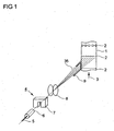
- Fig. 1 schematically shows in principle the process step of applying adhesive to a layer from which a honeycomb body is later to be produced together with other layers.
- a location especially one Layer 1, at least partially structured, with symbolically indicated structural extremes 2, that is to say structure minima and structure maxima, is moved in a direction of movement 3 relative to means 4 for applying adhesives.
- the means 4 for applying adhesive comprise a piezoelectric element 5, a nozzle 6, charging means 7, deflection means 8, and collecting means 9.
- the nozzle 6 is acted upon by the adhesive under a pressure of 2.5 bar or more.
- the nozzle 6 is set in motion by the piezoelectric element 5, to which a high-frequency AC voltage is applied. Vibration frequencies of more than 50 kHz, preferably more than 60 kHz, particularly preferably 100 kHz and more are preferred.
- Vibration frequencies of more than 50 kHz, preferably more than 60 kHz, particularly preferably 100 kHz and more are preferred.
- This drop jet 35 is electrostatically charged in the charging means 7.
- the drops of adhesive thus electrostatically charged are deflected by the deflecting means 8 by applying an electrostatic field.
- Fig. 1 the drop beam 35 is shown with different deflections. As a result, not only can adhesive points 10 be generated on the layer 1, but also adhesive lines 11.
- the adhesive ie the adhesive points 10 or adhesive lines 11, is applied directly adjacent to a structural extremum 2.
- the application of adhesive still lies in the area of the top of the structuring and not in the area of the side flank of the structuring, but directly adjacent to the structural extremum 2.
- the structural extremum 2 with which the at least partially structured layer 1 slides over the substantially smooth layer, is not provided with adhesive, so that the sliding friction is reduced in comparison to the winding with glue applied to the structural extreme 2.
- Fig. 2 shows schematically another embodiment of the means 4 for applying adhesive.
- an essentially smooth layer 12 is moved past a printing device 13 in the direction of movement 3, by means of which adhesive means 36 in the form of a drop jet 35 are applied in an application direction 41.
- the application direction 41 is essentially perpendicular to the direction of movement 3 of the layer 12.
- the printing device 13 comprises a piezoelectric element 5, charging means 7, deflection means 8 and collecting means 9.
- the piezoelectric element 5 is operated with a high-frequency alternating voltage which leads to an oscillation of the piezoelectric Element 5 leads in the direction of vibration 14.
- adhesive is supplied from an adhesive reservoir 16 through supply means 40 under high pressure to a nozzle 6.
- the vibrations of the piezoelectric element 5 produce a high-frequency continuous or quasi-continuous drop jet 35 therefrom. These drops 35 are electrostatically charged in the charging means 7 and deflected electrostatically in the deflecting means 8.
- Fig. 2 the drop beam 35 is shown with different deflections. The deflection takes place by applying respective voltages to the deflecting means 8 and the charging means 7. This allows the drop jet 35 to be moved relative to the position 1, 12.
- adhesive lines 11 are produced on an essentially smooth sheet-metal layer 12, which is shown in perspective. Here, very different lengths of the adhesive lines 11 can be generated.
- the drops of adhesive agent collected in the collecting means 9 are returned to the adhesive agent reservoir 16 via the return means 18 and possibly filters 19.
- the example shown is essentially a means 4 for applying adhesive, which works according to the continuous inkjet method.
- the second exemplary embodiment shown is a printing device 13 which works according to the drop-on-demand system. With such a system, no continuous high-frequency oscillation of a nozzle and thus a quasi-continuous drop jet is generated, rather individual drops 22 are generated by individual pulses.
- the same printing device 13 is shown at different times 1 to 4.
- the printing device 13 comprises a piezoelectric element 5, which can be provided with an electrical voltage pulse via contacts 20. The generation of drops is shown schematically at four different times 1 to 4. At time 1, the piezoelectric element 5 is in the rest position.
- Nozzle 6 and feed line 21 are filled with adhesive 36.
- a voltage pulse is applied to the piezoelectric element 5 via the contacts 20, which leads to a deflection of the piezoelectric element 5. This causes the adhesive 36 to move as symbolized by the two arrows.
- the voltage pulse in the piezoelectric element 5 is reduced again, so that it has already at least partially deformed back. This leads to a movement of the adhesive 36, as indicated by arrows.
- a drop 22 is ejected, which, however, has not yet been separated from the adhesive 36 in the nozzle 6. This takes place only in step 4, in which the piezoelectric element 5 is again in the rest position as at time 1.
- a detached Adhesive droplet 22 leaves the nozzle 6.
- Another method is the bubble jet method, in which a boiling film of the adhesive 36 is produced by briefly heating the nozzle 6. This creates a vapor bubble that throws a drop 22 of adhesive 36 out of the nozzle 6.
- the method is known from the prior art and at the same time represents a drop-on-demand method.
- Fig. 4 shows schematically the details of an adhesive application of a preferred embodiment of the method according to the invention.
- adhesive in the form of adhesive drops 22 is applied to an at least partially structured layer 1.
- the at least partially structured layer 1 is sinusoidal in the present example, but triangular waves or other structures could just as easily be present.
- the adhesive 4 is applied to the at least partially structured layer 1 by the means 4 for applying adhesive.
- the adhesive is applied in regions that are adjacent to structure extreme 2. If a honeycomb body is constructed from at least partially structured sheet metal layers 1 and possibly essentially smooth layers 12, the layers 1, 12 will move relative to one another when the layers 1, 12 are wound or twisted. This leads to the at least partially structured layers 1 slipping on the substantially smooth Layers 12.
- At least partially structured layers 1 and essentially smooth layers 12 must be connected to one another in order to build up a honeycomb body. This is often done by soldering, more precisely brazing, the layers to one another. The soldering takes place in the area of the structure extrema 2, so that when the at least partially structured layer 1 and the essentially smooth layer 12 come into contact, essentially triangular solder gussets form on both sides of the structure extremum 2.
- one of the great advantages of the present invention is that an adhesive can be applied directly adjacent to the structural extremes 2. This means that on the one hand the sliding friction between the layers 1, 12 is reduced during winding or twisting and on the other hand a soldering agent can be applied in the area of the extreme structure. A permanent and high-quality connection of the layers 1, 12 to one another can thus be established without the winding or twisting being made more difficult.
- the adhesive is applied directly adjacent to the structural extremes 2 in the manner according to the invention.
- Fig. 5 shows an example of two connected layers 1, 12.
- an at least partially structured layer 1 is connected to an essentially smooth layer 12.
- the at least partially structured layer 1 has structural extremes 2 against which the at least partially structured layer 1 bears against the essentially smooth layer 12.
- Processes were formed by soldering gussets 23 which connect the at least partially structured layer 1 to the substantially smooth layer 12.
- Fig. 6 shows schematically a structure of a device for producing honeycomb bodies.
- Fig. 6 shows means 23 for providing at least one at least partially structured metallic layer and possibly at least one essentially smooth metallic layer. These means can, for example, carry out the unwinding and severing, as well as, if necessary, structuring sheet metal layers of coils from smooth sheet metal foils, or they can also be made up according to fiber material, that is to say provide at least a certain length and, if necessary, structuring. These means 23 provide the required at least partially structured layers or, if necessary, essentially smooth layers.
- the means can have structuring means, which are not shown, by means of which an essentially structured layer is generated from a smooth layer, which is unwound, for example, from a coil.
- microstructuring means can be formed which form microstructures in the essentially smooth position.
- means 4 for applying adhesive are formed.
- stacking means 24 in which stacks are formed from essentially smooth and at least partially structured sheet metal layers.
- twisting means 25 in which one or more stacks produced in the stacking means 24 are twisted together.
- honeycomb bodies can be produced that have an S or involute shape. It is just as well possible not to form stacking means 24 and instead an at least partially structured layer or also at least partially structured layers and to wind up essentially smooth layers, for example to form a spiral honeycomb body.
- Soldering means 26 adjoin the twisting means 25, in which powdered solder is introduced into the wound honeycomb body.
- the soldering agent is followed by treatment agent 27, in which a thermal treatment is carried out, in which the solder introduced melts and connects the layers 1, 12 to one another.
- the individual means 23, 4, 24, 25, 26, 27 are connected to one another by connecting means 28, which enable the raw products to be transported from one means to the next.
- solder is applied in the soldering means 26 after stacking and twisting in the stacking means 24 and twisting means 25.
- Fig. 7 shows the example of a spirally wound honeycomb body different ways of applying adhesive 36, which are possible by means of the inventive method.
- the spirally wound honeycomb body 29 is spirally wound from an at least partially structured layer 1 and an essentially smooth layer 12.
- the honeycomb body 29 has channels 30 which extend through the honeycomb body 29.
- a first end face 37 can flow through the honeycomb body 29 to a second end face 38 in a flow direction 39.
- Fig. 7 shows various possibilities of how, according to the method according to the invention, an adhesive can be applied both to the at least partially structured layer 1 and to the essentially smooth layer 12.
- the adhesive 36 can be applied as an adhesive strip 31 on the end face or as an internal adhesive strip 32.
- the adhesive 36 is applied both to the at least partially structured layer 1 and to the substantially smooth layer Layer 12 continuous adhesive strips 33 can be formed. It is particularly preferred here to form them directly adjacent to the structure extremes 2 of the at least partially structured layer 1. In this case, the area of the structure which corresponds to the structure extremum 2 is not provided with adhesive 36. Furthermore, it is possible to provide only partial areas of the at least partially structured layer 1 with adhesive. Here, partial areas 34 can be formed in the flow direction with adhesive 36, which can be formed both on the end face and on the inside. Thus, several areas can be formed with adhesive 36 per structure. In all of these examples, the adhesive is applied according to the invention in the form of drops, preferably in the form of a drop jet, by means of a printing device such as, for example, a continuous inkjet printing device.
- a printing device such as, for example, a continuous inkjet printing device.
- solder powder When the solder powder is applied later, it adheres to the sections 31, 32, 33, 34 to which the adhesive 36 has been applied, so that the layers 1, 12 are connected to one another in these sections 31, 32, 33, 34.
- Fig. 8 shows another example of an advantageous embodiment of the method according to the invention.
- adhesive in the form of adhesive drops 22 is applied to an at least partially structured layer 1.
- the adhesive is applied essentially perpendicular to the surface 42 of the partial areas 43 to be provided with adhesive 36. That is, the adhesive is applied in a direction that is essentially the surface normal of the surface 42 to be provided with adhesive. This is done by a corresponding adjustment of the printing devices 13.
- the partial areas 42 to be provided with adhesive 36 are adjacent to the structural extremes 2.
- honeycomb bodies 29 advantageously allow very precise adhesive agents 36 to be applied to the areas in which a connection to adjacent layers is to be made later.
- adhesive 36 is applied by means of a printing technique, in particular also on the flank areas which are directly adjacent to an extreme structure 2.
- honeycomb bodies 29 which have a flexibility which is inhomogeneous across the flow direction 39 and / or essentially transverse to the flow direction 39.
Landscapes
- Engineering & Computer Science (AREA)
- Mechanical Engineering (AREA)
- Application Of Or Painting With Fluid Materials (AREA)
- Laminated Bodies (AREA)
- Exhaust Gas After Treatment (AREA)
- Filtering Materials (AREA)
- Catalysts (AREA)
- Ceramic Products (AREA)
- Particle Formation And Scattering Control In Inkjet Printers (AREA)
Claims (11)
- Procédé d'application d'un adhésif (36) sur des couches (1, 12) pour la fabrication d'un corps en nid d'abeilles (29), de préférence sur des couches au moins partiellement métalliques, comprenant les étapes suivantes :a. mise à disposition d'au moins une couche (1) au moins partiellement structurée et, le cas échéant, d'au moins une couche (12) sensiblement lisse ;b. application d'adhésif (36) au moins sur au moins une région partielle (10, 11, 31, 32, 33, 34, 43) de la couche (12) sensiblement lisse et/ou de la couche (1) au moins partiellement structurée ;c. fabrication d'un corps en nids d'abeilles ;e. mise en œuvre d'une étape de traitement thermique, la couche étant pourvue d'un matériau à braser, lequel reste adhéré sensiblement sur les régions partielles (10, 11, 31, 32, 33, 34, 43) des couches (1, 12), lesquelles régions partielles sont pourvues d'adhésif (36), l'adhésif (36) étant appliqué en forme de gouttes (22, 35), caractérisé en ce que l'adhésif (36) est imprimé selon un procédé du groupe :- procédé de Drop-on Demand,- procédé de Bubble Jet,- procédé de Continuous Inkjet.
- Procédé selon la revendication 1, caractérisé en ce que l'adhésif (36) est appliqué sur la couche (1) au moins partiellement structurée dans la région des flancs des structurations, de préférence à proximité d'un extrémum de structure (2).
- Procédé selon l'une des revendications précédentes, caractérisé en ce que l'adhésif (36) est appliqué au moyen d'une buse (6), laquelle est excitée par impulsion.
- Procédé selon l'une des revendications précédentes, caractérisé en ce que l'adhésif (36) est appliqué au moyen d'une buse (6), laquelle est excitée jusqu'à des oscillations à fréquences élevées, l'excitation étant effectuée en particulier à une fréquence d'au moins 50 kHz, de préférence d'au moins 60 kHz, de manière particulièrement préférée d'au moins 100 kHz.
- Procédé selon la revendication 3 ou 4, caractérisé en ce que l'adhésif dans la buse (6) présente une pression de plus de 2 bars, de préférence de plus de 2,5 bars.
- Procédé selon l'une des revendications 3 à 5, caractérisé en ce que l'excitation de la buse (6) est effectuée au moyen d'un élément piézoélectrique (5).
- Procédé selon l'une des revendications précédentes, caractérisé en ce que les gouttes d'adhésif (22, 35) sont chargées de manière électrostatique et déviées de manière électrostatique.
- Procédé selon la revendication 7, caractérisé en ce que des gouttes d'adhésif (22, 35) qui ne doivent pas être appliquées sur les couches (1, 12) sont dirigées de façon électrostatique dans un moyen de recueil (9) et sont recyclées.
- Procédé selon la revendication 7 ou 8, caractérisé en ce que le positionnement de l'adhésif (36) sur les couches (1, 12) est obtenu au moins en partie par une déviation électrostatique ciblée des gouttes d'adhésif (22, 35) avant de rencontrer les couches (1, 12).
- Procédé selon la revendication 1 ou 2, caractérisé en ce que les gouttes d'adhésif (22) sont générées par le réchauffement de courte durée de l'adhésif (35) au-delà de son point d'ébullition dans une buse (6).
- Procédé selon l'une des revendications précédentes, caractérisé en ce que les gouttes d'adhésif (10, 22) sur la couche (1, 12) présentent un diamètre moyen de 0,05 à 0,7 mm, de préférence de 0,1 à 0,4 mm, de manière particulièrement préférée de 0,1 à 0,3 mm.
Applications Claiming Priority (3)
| Application Number | Priority Date | Filing Date | Title |
|---|---|---|---|
| DE10338360A DE10338360A1 (de) | 2003-08-21 | 2003-08-21 | Verfahren und Vorrichtung zur Herstellung eines Wabenkörpers |
| PCT/EP2004/008804 WO2005021198A1 (fr) | 2003-08-21 | 2004-08-06 | Procede et dispositif de production d'un corps a nids d'abeille |
| EP04741375A EP1663560B1 (fr) | 2003-08-21 | 2004-08-06 | Procede et dispositif de production d'un corps a nids d'abeille |
Related Parent Applications (2)
| Application Number | Title | Priority Date | Filing Date |
|---|---|---|---|
| EP04741375A Division EP1663560B1 (fr) | 2003-08-21 | 2004-08-06 | Procede et dispositif de production d'un corps a nids d'abeille |
| PCT/EP2004/008804 Previously-Filed-Application WO2005021198A1 (fr) | 2003-08-21 | 2004-08-06 | Procede et dispositif de production d'un corps a nids d'abeille |
Publications (2)
| Publication Number | Publication Date |
|---|---|
| EP2060357A1 EP2060357A1 (fr) | 2009-05-20 |
| EP2060357B1 true EP2060357B1 (fr) | 2020-01-22 |
Family
ID=34223102
Family Applications (2)
| Application Number | Title | Priority Date | Filing Date |
|---|---|---|---|
| EP04741375A Active EP1663560B1 (fr) | 2003-08-21 | 2004-08-06 | Procede et dispositif de production d'un corps a nids d'abeille |
| EP08021590.8A Active EP2060357B1 (fr) | 2003-08-21 | 2004-08-06 | Procédé de fabrication d'un corps en nid d'abeille |
Family Applications Before (1)
| Application Number | Title | Priority Date | Filing Date |
|---|---|---|---|
| EP04741375A Active EP1663560B1 (fr) | 2003-08-21 | 2004-08-06 | Procede et dispositif de production d'un corps a nids d'abeille |
Country Status (10)
| Country | Link |
|---|---|
| US (1) | US20060162854A1 (fr) |
| EP (2) | EP1663560B1 (fr) |
| JP (1) | JP4861174B2 (fr) |
| KR (1) | KR101048259B1 (fr) |
| CN (1) | CN1839007B (fr) |
| DE (2) | DE10338360A1 (fr) |
| ES (1) | ES2318299T3 (fr) |
| PL (1) | PL1663560T3 (fr) |
| RU (1) | RU2357840C2 (fr) |
| WO (1) | WO2005021198A1 (fr) |
Families Citing this family (4)
| Publication number | Priority date | Publication date | Assignee | Title |
|---|---|---|---|---|
| US20090223163A1 (en) * | 2008-03-10 | 2009-09-10 | Shu Ching Quek | Wind Turbine Tower Including An Induction Brazed Joint And A Method Of Fabricating The Wind Turbine Tower |
| DE102009018825A1 (de) | 2009-04-24 | 2010-10-28 | Emitec Gesellschaft Für Emissionstechnologie Mbh | Blechlage mit Anti-Diffusionsstrukturen und metallischer Wabenkörper mit mindestens einer solchen Blechlage |
| DE102011008378A1 (de) | 2011-01-12 | 2012-07-12 | Emitec Gesellschaft Für Emissionstechnologie Mbh | Thermoelektrisches Modul mit Mitteln zur Kompensation einer Wärmeausdehnung |
| CN102922069B (zh) * | 2012-11-03 | 2015-12-09 | 台州欧信环保净化器有限公司 | 一种金属蜂窝载体焊接的方法 |
Family Cites Families (26)
| Publication number | Priority date | Publication date | Assignee | Title |
|---|---|---|---|---|
| US3479731A (en) * | 1967-06-13 | 1969-11-25 | Gen Motors Corp | Brazing method |
| US3579245A (en) * | 1967-12-07 | 1971-05-18 | Teletype Corp | Method of transferring liquid |
| DE2902779C2 (de) * | 1979-01-25 | 1985-09-26 | Süddeutsche Kühlerfabrik Julius Fr. Behr GmbH & Co. KG, 7000 Stuttgart | Matrix für einen katalytischen Reaktor zur Abgasreinigung bei Brennkraftmaschinen |
| EP0223058B1 (fr) * | 1985-10-25 | 1989-10-11 | INTERATOM Gesellschaft mit beschränkter Haftung | Procédé de soudage du support métallique d'un appareil catalytique |
| EP0245737B1 (fr) * | 1986-05-12 | 1989-08-23 | INTERATOM Gesellschaft mit beschränkter Haftung | Corps en forme de nid d'abeilles, en particulier support pour catalyseur, avec des tôles métalliques superposées, repliées en boucles de sens contraire, et son procédé de fabrication |
| DE3818512A1 (de) * | 1988-05-31 | 1989-12-07 | Interatom | Verfahren zum beleimen und beloten eines metallischen katalysator-traegerkoerpers und zugehoerige vorrichtung |
| BR8907458A (pt) * | 1988-09-22 | 1991-04-02 | Emitec Emissionstechnologie | Corpo alveolar,especialmente corpo de suporte de catalisador,constituido de uma multiplicidade de pilhas de chapa entrelacadas |
| DE3908453A1 (de) * | 1989-03-15 | 1990-09-20 | Mf Applikationstechnik Gmbh | Verfahren und vorrichtung zum diskontinuierlichen ausbringen von an der luft erstarrenden applikationsfluessigkeiten aus auftragsduesen |
| EP0474909B1 (fr) * | 1990-09-13 | 1994-01-12 | Nippon Steel Corporation | Méthode de soudage d'un corps alvéolaire |
| DE4219145C1 (de) * | 1992-06-11 | 1994-03-17 | Emitec Emissionstechnologie | Verfahren und Vorrichtung zum Beloten eines metallischen Wabenkörpers |
| DE4416539C1 (de) * | 1994-05-10 | 1995-07-20 | Emitec Emissionstechnologie | Verfahren zum Beloten von metallischen Strukturen mit einem reversibel unterschiedliche Zustände aufweisenden Haftmaterial |
| JPH0872242A (ja) * | 1994-09-07 | 1996-03-19 | Matsushita Electric Ind Co Ltd | インクジェットヘッド |
| US5560543A (en) * | 1994-09-19 | 1996-10-01 | Board Of Regents, The University Of Texas System | Heat-resistant broad-bandwidth liquid droplet generators |
| EP0861136B1 (fr) * | 1995-11-16 | 2001-01-24 | Nordson Corporation | Dispositif et procede pour la diffusion de petites quantites de materiau liquide |
| US5988480A (en) * | 1997-12-12 | 1999-11-23 | Micron Technology, Inc. | Continuous mode solder jet apparatus |
| GB9808182D0 (en) * | 1998-04-17 | 1998-06-17 | The Technology Partnership Plc | Liquid projection apparatus |
| US20010032887A1 (en) * | 1999-02-19 | 2001-10-25 | Everett Alan L. | Precision dispensing tip and method |
| EP1268165B1 (fr) * | 2000-03-24 | 2004-10-06 | GENERIS GmbH | Procede et dispositif de fabrication d'un composant de construction suivant une technique de deposition multicouche, et moule ou noyau tel que fabrique par le procede |
| WO2002030566A1 (fr) * | 2000-10-10 | 2002-04-18 | Nippon Steel Corporation | Procede de production de corps en nid d'abeilles |
| JP2002232123A (ja) * | 2001-01-31 | 2002-08-16 | Mitsubishi Electric Corp | 複合回路基体の製造方法 |
| JP2002252245A (ja) * | 2001-02-22 | 2002-09-06 | Mitsubishi Electric Corp | 半導体装置の製造方法 |
| US6617045B2 (en) * | 2001-03-02 | 2003-09-09 | Nippon Steel Corporation | Metallic carrier, for automobile exhaust gas purification, made of thin metal foil and method of producing the same |
| DE10151487C1 (de) * | 2001-10-18 | 2002-10-02 | Emitec Emissionstechnologie | Verfahren zur Herstellung einer metallischen Struktur sowie Vorrichtung zur Benetzung einer metallischen Struktur mit einem Klebstoff |
| DE10200069A1 (de) | 2002-01-03 | 2003-07-24 | Emitec Emissionstechnologie | Wabenstruktur und Verfahren zu deren Beleimung und Belotung |
| US6898082B2 (en) * | 2002-05-10 | 2005-05-24 | Serguei V. Dessiatoun | Enhanced heat transfer structure with heat transfer members of variable density |
| DE102005026532A1 (de) * | 2005-06-08 | 2006-12-14 | Bhs Corrugated Maschinen- Und Anlagenbau Gmbh | Wellpappeanlage |
-
2003
- 2003-08-21 DE DE10338360A patent/DE10338360A1/de not_active Withdrawn
-
2004
- 2004-08-06 ES ES04741375T patent/ES2318299T3/es active Active
- 2004-08-06 CN CN2004800240480A patent/CN1839007B/zh active Active
- 2004-08-06 EP EP04741375A patent/EP1663560B1/fr active Active
- 2004-08-06 KR KR1020067003554A patent/KR101048259B1/ko active IP Right Grant
- 2004-08-06 EP EP08021590.8A patent/EP2060357B1/fr active Active
- 2004-08-06 RU RU2006108469/02A patent/RU2357840C2/ru not_active IP Right Cessation
- 2004-08-06 PL PL04741375T patent/PL1663560T3/pl unknown
- 2004-08-06 DE DE502004008744T patent/DE502004008744D1/de active Active
- 2004-08-06 WO PCT/EP2004/008804 patent/WO2005021198A1/fr active Application Filing
- 2004-08-06 JP JP2006523563A patent/JP4861174B2/ja active Active
-
2006
- 2006-02-21 US US11/359,948 patent/US20060162854A1/en not_active Abandoned
Also Published As
| Publication number | Publication date |
|---|---|
| WO2005021198A1 (fr) | 2005-03-10 |
| PL1663560T3 (pl) | 2009-06-30 |
| KR101048259B1 (ko) | 2011-07-08 |
| EP1663560B1 (fr) | 2008-12-24 |
| US20060162854A1 (en) | 2006-07-27 |
| CN1839007B (zh) | 2010-04-14 |
| JP2007502698A (ja) | 2007-02-15 |
| DE10338360A1 (de) | 2005-03-31 |
| DE502004008744D1 (de) | 2009-02-05 |
| ES2318299T3 (es) | 2009-05-01 |
| JP4861174B2 (ja) | 2012-01-25 |
| CN1839007A (zh) | 2006-09-27 |
| EP1663560A1 (fr) | 2006-06-07 |
| KR20070006658A (ko) | 2007-01-11 |
| EP2060357A1 (fr) | 2009-05-20 |
| RU2006108469A (ru) | 2007-09-27 |
| RU2357840C2 (ru) | 2009-06-10 |
Similar Documents
| Publication | Publication Date | Title |
|---|---|---|
| EP0422000B1 (fr) | Procede d'encollage et de brasage du support metallique d'un catalyseur | |
| EP0713773B1 (fr) | Générateur de micro-gouttelettes en particulier pour imprimante à jet d'encre | |
| DE69133583T2 (de) | Auf Abruf arbeitender Tintenstrahldruckkopf | |
| EP3804863B1 (fr) | Procédé d'application et système d'application | |
| DE2944005C2 (fr) | ||
| DE102009026636B4 (de) | Verfahren zum Verschweißen einer Membran mit einem Träger bei der Herstellung eines Membranverneblers | |
| EP2422058B1 (fr) | Corps en nid d'abeilles pouvant être chauffé sur plusieurs niveaux | |
| WO2006058666A1 (fr) | Matiere de liaison permettant de positionner une matiere de brasage dotee d'une matiere support et un corps moule de brasage pose en discontinu sur cette derniere; procede de production d'un corps nid d'abeilles a l'aide d'une telle matiere de liaison; corps nid d'abeilles correspondant | |
| DE3248087A1 (de) | Fluessigkeitsstrahlkopf | |
| EP1463599B1 (fr) | Structure alveolaire et procede de collage et de brasage de cette structure | |
| DE69932463T2 (de) | Tropfenerzeugungsvorrichtung | |
| EP1934011B2 (fr) | Dispositif d'application de metal d'apport de brasage fort | |
| DE69529354T2 (de) | Tintenstrahlkopf | |
| EP1740339B1 (fr) | Application d'adhesif pour realiser une structure qui resiste aux temperatures elevees | |
| EP2060357B1 (fr) | Procédé de fabrication d'un corps en nid d'abeille | |
| EP1499168B1 (fr) | Procédé et dispositif pour la réalisation d'un système comprenant un composant disposé à une position predeterminée à la surface d'un substrat | |
| EP0307403A1 (fr) | Tete d'ecriture a l'encre avec membrane a excitation piezoelectrique. | |
| DE3007189C2 (fr) | ||
| EP2260190A1 (fr) | Corps en nid-d'abeilles et procédé de fabrication par brasage d'un corps en nid-d'abeilles | |
| EP0617650B1 (fr) | Procede pour le brasage des supports de catalyseurs de pots d'echappement | |
| EP1742756B1 (fr) | Application de lubrifiant pour realiser une structure qui resiste aux temperatures elevees | |
| DE60115189T2 (de) | Vorrichtung zur verstärkung der umlenkung von tintentropfen und verfahren zum vergrössern der divergenz von tintentropfen | |
| DE102006025865A1 (de) | Bondverfahren | |
| EP0358723B1 (fr) | Procédé de fabrication d'une tête piezoélectrique d'impression à l'encre | |
| DE19747178C2 (de) | Tintenstrahlkopf mit piezoelektrischem Antrieb und Verfahren zur Herstellung desselben |
Legal Events
| Date | Code | Title | Description |
|---|---|---|---|
| PUAI | Public reference made under article 153(3) epc to a published international application that has entered the european phase |
Free format text: ORIGINAL CODE: 0009012 |
|
| AC | Divisional application: reference to earlier application |
Ref document number: 1663560 Country of ref document: EP Kind code of ref document: P |
|
| AK | Designated contracting states |
Kind code of ref document: A1 Designated state(s): DE ES FR GB IT PL |
|
| 17P | Request for examination filed |
Effective date: 20090527 |
|
| AKX | Designation fees paid |
Designated state(s): DE ES FR GB IT PL |
|
| 17Q | First examination report despatched |
Effective date: 20100621 |
|
| APBK | Appeal reference recorded |
Free format text: ORIGINAL CODE: EPIDOSNREFNE |
|
| APBN | Date of receipt of notice of appeal recorded |
Free format text: ORIGINAL CODE: EPIDOSNNOA2E |
|
| APAZ | Date of receipt of statement of grounds of appeal deleted |
Free format text: ORIGINAL CODE: EPIDOSDNOA3E |
|
| APBR | Date of receipt of statement of grounds of appeal recorded |
Free format text: ORIGINAL CODE: EPIDOSNNOA3E |
|
| APBR | Date of receipt of statement of grounds of appeal recorded |
Free format text: ORIGINAL CODE: EPIDOSNNOA3E |
|
| APAF | Appeal reference modified |
Free format text: ORIGINAL CODE: EPIDOSCREFNE |
|
| APAF | Appeal reference modified |
Free format text: ORIGINAL CODE: EPIDOSCREFNE |
|
| APAF | Appeal reference modified |
Free format text: ORIGINAL CODE: EPIDOSCREFNE |
|
| RAP1 | Party data changed (applicant data changed or rights of an application transferred) |
Owner name: CONTINENTAL AUTOMOTIVE GMBH |
|
| APBT | Appeal procedure closed |
Free format text: ORIGINAL CODE: EPIDOSNNOA9E |
|
| GRAP | Despatch of communication of intention to grant a patent |
Free format text: ORIGINAL CODE: EPIDOSNIGR1 |
|
| STAA | Information on the status of an ep patent application or granted ep patent |
Free format text: STATUS: GRANT OF PATENT IS INTENDED |
|
| INTG | Intention to grant announced |
Effective date: 20190820 |
|
| GRAS | Grant fee paid |
Free format text: ORIGINAL CODE: EPIDOSNIGR3 |
|
| GRAA | (expected) grant |
Free format text: ORIGINAL CODE: 0009210 |
|
| STAA | Information on the status of an ep patent application or granted ep patent |
Free format text: STATUS: THE PATENT HAS BEEN GRANTED |
|
| RAP1 | Party data changed (applicant data changed or rights of an application transferred) |
Owner name: VITESCO TECHNOLOGIES GMBH |
|
| AC | Divisional application: reference to earlier application |
Ref document number: 1663560 Country of ref document: EP Kind code of ref document: P |
|
| AK | Designated contracting states |
Kind code of ref document: B1 Designated state(s): DE ES FR GB IT PL |
|
| REG | Reference to a national code |
Ref country code: GB Ref legal event code: FG4D Free format text: NOT ENGLISH |
|
| REG | Reference to a national code |
Ref country code: DE Ref legal event code: R096 Ref document number: 502004015847 Country of ref document: DE |
|
| REG | Reference to a national code |
Ref country code: DE Ref legal event code: R097 Ref document number: 502004015847 Country of ref document: DE |
|
| PG25 | Lapsed in a contracting state [announced via postgrant information from national office to epo] |
Ref country code: ES Free format text: LAPSE BECAUSE OF FAILURE TO SUBMIT A TRANSLATION OF THE DESCRIPTION OR TO PAY THE FEE WITHIN THE PRESCRIBED TIME-LIMIT Effective date: 20200122 |
|
| PLBE | No opposition filed within time limit |
Free format text: ORIGINAL CODE: 0009261 |
|
| STAA | Information on the status of an ep patent application or granted ep patent |
Free format text: STATUS: NO OPPOSITION FILED WITHIN TIME LIMIT |
|
| 26N | No opposition filed |
Effective date: 20201023 |
|
| PG25 | Lapsed in a contracting state [announced via postgrant information from national office to epo] |
Ref country code: IT Free format text: LAPSE BECAUSE OF FAILURE TO SUBMIT A TRANSLATION OF THE DESCRIPTION OR TO PAY THE FEE WITHIN THE PRESCRIBED TIME-LIMIT Effective date: 20200122 |
|
| PG25 | Lapsed in a contracting state [announced via postgrant information from national office to epo] |
Ref country code: PL Free format text: LAPSE BECAUSE OF FAILURE TO SUBMIT A TRANSLATION OF THE DESCRIPTION OR TO PAY THE FEE WITHIN THE PRESCRIBED TIME-LIMIT Effective date: 20200122 |
|
| GBPC | Gb: european patent ceased through non-payment of renewal fee |
Effective date: 20200806 |
|
| PG25 | Lapsed in a contracting state [announced via postgrant information from national office to epo] |
Ref country code: GB Free format text: LAPSE BECAUSE OF NON-PAYMENT OF DUE FEES Effective date: 20200806 |
|
| REG | Reference to a national code |
Ref country code: DE Ref legal event code: R084 Ref document number: 502004015847 Country of ref document: DE |
|
| P01 | Opt-out of the competence of the unified patent court (upc) registered |
Effective date: 20230530 |
|
| REG | Reference to a national code |
Ref country code: DE Ref legal event code: R081 Ref document number: 502004015847 Country of ref document: DE Owner name: EMITEC TECHNOLOGIES GMBH, DE Free format text: FORMER OWNER: VITESCO TECHNOLOGIES GMBH, 30165 HANNOVER, DE |
|
| PGFP | Annual fee paid to national office [announced via postgrant information from national office to epo] |
Ref country code: FR Payment date: 20230824 Year of fee payment: 20 Ref country code: DE Payment date: 20230831 Year of fee payment: 20 |