EP2060357B1 - Method for producing a honeycomb body - Google Patents
Method for producing a honeycomb body Download PDFInfo
- Publication number
- EP2060357B1 EP2060357B1 EP08021590.8A EP08021590A EP2060357B1 EP 2060357 B1 EP2060357 B1 EP 2060357B1 EP 08021590 A EP08021590 A EP 08021590A EP 2060357 B1 EP2060357 B1 EP 2060357B1
- Authority
- EP
- European Patent Office
- Prior art keywords
- adhesive
- layers
- layer
- drops
- nozzle
- Prior art date
- Legal status (The legal status is an assumption and is not a legal conclusion. Google has not performed a legal analysis and makes no representation as to the accuracy of the status listed.)
- Active
Links
- 238000004519 manufacturing process Methods 0.000 title description 10
- 239000000853 adhesive Substances 0.000 claims description 213
- 230000001070 adhesive effect Effects 0.000 claims description 210
- 238000000034 method Methods 0.000 claims description 86
- 229910000679 solder Inorganic materials 0.000 claims description 37
- 239000000463 material Substances 0.000 claims description 15
- 230000005284 excitation Effects 0.000 claims description 11
- 238000010438 heat treatment Methods 0.000 claims description 9
- 238000009835 boiling Methods 0.000 claims description 5
- 230000010355 oscillation Effects 0.000 claims description 5
- 238000007669 thermal treatment Methods 0.000 claims description 5
- 239000010410 layer Substances 0.000 description 177
- 241000264877 Hippospongia communis Species 0.000 description 58
- 238000007639 printing Methods 0.000 description 38
- 238000004804 winding Methods 0.000 description 17
- 238000005476 soldering Methods 0.000 description 16
- 239000002184 metal Substances 0.000 description 14
- 230000033001 locomotion Effects 0.000 description 10
- 239000000843 powder Substances 0.000 description 7
- 239000003795 chemical substances by application Substances 0.000 description 6
- 229920000914 Metallic fiber Polymers 0.000 description 5
- 239000011888 foil Substances 0.000 description 5
- 239000003292 glue Substances 0.000 description 5
- 239000002131 composite material Substances 0.000 description 4
- 239000002245 particle Substances 0.000 description 4
- 230000015572 biosynthetic process Effects 0.000 description 3
- 239000000919 ceramic Substances 0.000 description 3
- 238000010276 construction Methods 0.000 description 3
- 239000000835 fiber Substances 0.000 description 3
- 239000007788 liquid Substances 0.000 description 3
- MWUXSHHQAYIFBG-UHFFFAOYSA-N nitrogen oxide Inorganic materials O=[N] MWUXSHHQAYIFBG-UHFFFAOYSA-N 0.000 description 3
- 238000005219 brazing Methods 0.000 description 2
- 239000003054 catalyst Substances 0.000 description 2
- 230000000694 effects Effects 0.000 description 2
- 230000005686 electrostatic field Effects 0.000 description 2
- 239000002657 fibrous material Substances 0.000 description 2
- 239000007789 gas Substances 0.000 description 2
- 238000007641 inkjet printing Methods 0.000 description 2
- 239000000155 melt Substances 0.000 description 2
- 238000002844 melting Methods 0.000 description 2
- 230000008018 melting Effects 0.000 description 2
- 238000003860 storage Methods 0.000 description 2
- 239000000126 substance Substances 0.000 description 2
- 239000004820 Pressure-sensitive adhesive Substances 0.000 description 1
- 238000004026 adhesive bonding Methods 0.000 description 1
- 239000012790 adhesive layer Substances 0.000 description 1
- 229910045601 alloy Inorganic materials 0.000 description 1
- 239000000956 alloy Substances 0.000 description 1
- 238000000576 coating method Methods 0.000 description 1
- 230000001419 dependent effect Effects 0.000 description 1
- 238000011161 development Methods 0.000 description 1
- 230000018109 developmental process Effects 0.000 description 1
- 238000001914 filtration Methods 0.000 description 1
- 229930195733 hydrocarbon Natural products 0.000 description 1
- 150000002430 hydrocarbons Chemical class 0.000 description 1
- 230000001939 inductive effect Effects 0.000 description 1
- 239000007769 metal material Substances 0.000 description 1
- 239000000203 mixture Substances 0.000 description 1
- 239000003960 organic solvent Substances 0.000 description 1
- 239000011148 porous material Substances 0.000 description 1
- 230000005855 radiation Effects 0.000 description 1
- 239000007787 solid Substances 0.000 description 1
- 239000002904 solvent Substances 0.000 description 1
- 239000007921 spray Substances 0.000 description 1
- 239000002918 waste heat Substances 0.000 description 1
- XLYOFNOQVPJJNP-UHFFFAOYSA-N water Substances O XLYOFNOQVPJJNP-UHFFFAOYSA-N 0.000 description 1
- 238000003466 welding Methods 0.000 description 1
Images


Classifications
-
- B—PERFORMING OPERATIONS; TRANSPORTING
- B23—MACHINE TOOLS; METAL-WORKING NOT OTHERWISE PROVIDED FOR
- B23K—SOLDERING OR UNSOLDERING; WELDING; CLADDING OR PLATING BY SOLDERING OR WELDING; CUTTING BY APPLYING HEAT LOCALLY, e.g. FLAME CUTTING; WORKING BY LASER BEAM
- B23K1/00—Soldering, e.g. brazing, or unsoldering
- B23K1/0008—Soldering, e.g. brazing, or unsoldering specially adapted for particular articles or work
- B23K1/0014—Brazing of honeycomb sandwich structures
-
- B—PERFORMING OPERATIONS; TRANSPORTING
- B23—MACHINE TOOLS; METAL-WORKING NOT OTHERWISE PROVIDED FOR
- B23K—SOLDERING OR UNSOLDERING; WELDING; CLADDING OR PLATING BY SOLDERING OR WELDING; CUTTING BY APPLYING HEAT LOCALLY, e.g. FLAME CUTTING; WORKING BY LASER BEAM
- B23K1/00—Soldering, e.g. brazing, or unsoldering
- B23K1/20—Preliminary treatment of work or areas to be soldered, e.g. in respect of a galvanic coating
-
- B—PERFORMING OPERATIONS; TRANSPORTING
- B23—MACHINE TOOLS; METAL-WORKING NOT OTHERWISE PROVIDED FOR
- B23K—SOLDERING OR UNSOLDERING; WELDING; CLADDING OR PLATING BY SOLDERING OR WELDING; CUTTING BY APPLYING HEAT LOCALLY, e.g. FLAME CUTTING; WORKING BY LASER BEAM
- B23K2101/00—Articles made by soldering, welding or cutting
- B23K2101/02—Honeycomb structures
-
- Y—GENERAL TAGGING OF NEW TECHNOLOGICAL DEVELOPMENTS; GENERAL TAGGING OF CROSS-SECTIONAL TECHNOLOGIES SPANNING OVER SEVERAL SECTIONS OF THE IPC; TECHNICAL SUBJECTS COVERED BY FORMER USPC CROSS-REFERENCE ART COLLECTIONS [XRACs] AND DIGESTS
- Y10—TECHNICAL SUBJECTS COVERED BY FORMER USPC
- Y10T—TECHNICAL SUBJECTS COVERED BY FORMER US CLASSIFICATION
- Y10T156/00—Adhesive bonding and miscellaneous chemical manufacture
- Y10T156/10—Methods of surface bonding and/or assembly therefor
- Y10T156/1002—Methods of surface bonding and/or assembly therefor with permanent bending or reshaping or surface deformation of self sustaining lamina
- Y10T156/1025—Methods of surface bonding and/or assembly therefor with permanent bending or reshaping or surface deformation of self sustaining lamina to form undulated to corrugated sheet and securing to base with parts of shaped areas out of contact
Definitions
- the present invention relates to a method for applying adhesive to layers for the production of honeycomb bodies, such as are used in particular as catalyst support bodies, adsorbers and / or filter bodies in automobile construction.
- Honeycomb bodies wound or layered and layered and twisted from layers, in particular metallic layers, are known in various forms. A distinction is made primarily between two typical designs for honeycomb bodies made from layers.
- An early design for which the DE 29 02 779 A1 Typical examples show, is the spiral design, in which essentially a smooth and a corrugated sheet layer are placed on top of each other and wound up in a spiral.
- the honeycomb body is constructed from a multiplicity of alternatingly arranged smooth and corrugated or differently corrugated sheet metal layers, the sheet metal layers initially forming one or more stacks which are intertwined with one another.
- these layers In order to produce a honeycomb body, these layers must be connected to one another. Various connection techniques are possible for this. Brazing processes in which the layers are brazed together, at least in some areas, have gained great importance on the market. This is it required to introduce an additional material, the solder material, which has a lower melting point than the layers, into the honeycomb body. By heating the honeycomb body above the melting point of the solder material, the solder melts and connects the layers to one another when it cools down.
- solder material can be introduced into the honeycomb body in different forms, for example as a solder foil or solder powder. Solder foil is inserted or glued in the areas in which layers are to be connected to one another, while solder powder is either introduced into the honeycomb body without an adhesive or is applied in certain partial areas of the honeycomb body by means of an adhesive.
- solder powder is introduced into the honeycomb body without adhesive, it is practically not possible to connect only certain, for example axially spaced, partial areas of the layers to one another. If a locally inhomogeneous connection of the layers to one another, i.e. a connection that is not continuous in the direction of flow and / or essentially transversely to the direction of flow, or also the layers with a jacket tube enclosing the honeycomb body, the application of a solder powder is desirable Adhesive necessary.
- the EP 0 422 000 B2 the application of an adhesive using rollers.
- the adhesive is applied here before the layers are wrapped or stacked.
- the adhesive in liquid form using capillary forces known.
- the honeycomb body is brought into contact with a liquid adhesive after winding or stacking and twisting the layers, which rises due to the capillary forces in the capillaries formed by the contact areas of smooth and corrugated layers.
- a method for gluing and soldering a honeycomb structure is carried out, in which an average solder diameter of a powdered solder is selected which is smaller than 15% of the corrugation height of a structured film of the honeycomb structure.
- a minimum glue strip width is determined and at least some of the corrugations are provided with glue corresponding to the glue strip width, in particular using distributor rollers, spray nozzles, adhesive strips and the like.
- the soldering is carried out with a coordinated solder diameter, whereby the film thickness is also taken into account. This ensures that the foil does not alloy.
- the one in another technical field US 5,810,988 A is aimed at producing uniformly shaped drops or microscopic spherical bodies. For this purpose, a trajectory of droplets generated by printing is determined and the droplets are cooled in flight. The solid, microscopic spherical bodies produced in this way are then collected.
- step c) comprises stacking at least one at least partially structured and at least one essentially smooth layer to form at least one stack.
- step d) comprises twisting the at least one stack of layers and / or winding up at least one at least partially structured layer and optionally at least one essentially smooth layer to form a honeycomb body.
- the honeycomb body be provided with powdered solder material after step b) and before step e).
- the application of the solder material in liquid form, in particular in drop form, is also possible according to the invention. It is preferred here that the drops of solder material at least partially cover the drops of adhesive on the layers, preferably cover as large an area as possible. It is also possible in step b) to apply a solder paste, in particular a mixture of powdered solder material and a viscous adhesive, in drop form instead of a pure adhesive.
- honeycomb bodies which are soldered to one another in some subregions, while they are not soldered to one another in other subregions, so that honeycomb bodies with an inhomogeneous connection can be realized in a simple manner.
- honeycomb bodies can be produced in an advantageous manner that are inhomogeneous with regard to their elasticity, that is to say they have partial areas that are more elastic or less elastic than other partial areas.
- the application of the adhesive in drop form permits a local accuracy of the adhesive application, which is at least in the order of magnitude of the drop diameter, so that a locally very precise limitation of the partial areas of the layers to which adhesive is applied can be achieved.
- the thermal treatment step can be carried out by a soldering process in a soldering furnace, but it is also possible to achieve heating by inductive soldering or radiation soldering or also by the waste heat of a welding process.
- the adhesives used are preferably low-viscosity pressure-sensitive adhesives, preferably based on a polarizable solvent, in particular water or organic solvents. It is also preferred to use known and proven adhesives to build honeycomb bodies.
- the adhesive is applied to an at least partially structured layer in the region of the flanks of the structuring, preferably close to an extreme structure.
- a honeycomb body is built up by winding an essentially smooth and an at least partially structured layer
- the structural extremes, i.e. structure minima and structure maxima, of the at least partially structured layer rest on corresponding areas of the essentially smooth layers after the winding.
- the contact surfaces form the Contact areas between the layers in which a solder connection is to be formed later. This is done by introducing solder powder in the vicinity of the structural extremes, so that at least one, preferably two, solder gussets form adjacent to the structural extremes during soldering. These solder gussets can be approximately triangular, for example.
- solder gussets form directly adjacent to the structural extremes, while the structural extremity itself does not contribute to the solder connection between the layers ,
- the adhesive is now applied to the flanks of the structuring near an extreme structure, the solder powder adheres precisely in the areas that are to be joined later, on the one hand, and on the other hand no adhesive is applied to the extreme structure itself.
- the two layers essentially slide onto the extreme structure. If there is glue on the extreme structure, this relative movement is hindered and the winding or twisting is made more difficult. Applying the adhesive to the flanks of the structuring thus results in improved winding or twisting capability, the bonding of the layers to one another nevertheless being achieved with high reliability.
- the adhesive is printed namely using a drop-on-demand method, a bubble jet method and / or a continuous inkjet method.
- Drop-on-demand processes are printing processes which are characterized by the fact that a drop of the adhesive is only generated when a specific point on the layers is to be printed. If one considers a printing device which can emit an adhesive drop and the corresponding area of the layer on which this adhesive drop can be applied, an adhesive drop is only generated when the corresponding area of the layer is to be provided with adhesive. If no adhesive is to be applied, no adhesive drop is generated.
- Piezoelectric actuators are electromechanical transducers based on the piezoelectric effect.
- the application of an AC voltage to the piezoelectric element leads to mechanical vibrations.
- the mechanical vibrations cause drops of the material to be printed which leave the nozzle at a relatively high speed. These drops hit the material to be printed and stick there.
- the printing device which contains, for example, the piezoelectric actuator just described, it is possible to print on certain partial areas of the layer and not on certain partial areas.
- the adhesive drops are not generated by means of a piezoelectric transducer, but by using thermal actuators. These are heating elements which are formed in a nozzle and which are acted upon by the material to be printed, that is to say the adhesive. These heating elements briefly generate a temperature locally in the nozzle that is significantly above the boiling point of the adhesive.
- the adhesive begins to boil locally as a film, after which a closed vapor bubble forms after a short time.
- This vapor bubble drives a drop of the substance to be printed out of the nozzle, whereby pressures of 10 bar or more and outlet speeds of 10 m / sec and more can be achieved.
- the vapor bubble then collapses, resulting in the suction of adhesive due to the capillary forces.
- a distinction is made between different printing techniques which are generally known as edge and side shooters.
- the continuous inkjet method is a known printing method in which a continuous jet of ink drops is generated, which is printed by positioning the printhead and / or electrostatic deflection in predetermined partial areas.
- a continuous jet of adhesive drops is generated which is directed onto the partial regions of the layers to be provided with adhesive.
- the drops of adhesive then adhere to the layer.
- the electrostatic deflection advantageously not only allows printing of dots, but also the printing of overlapping dots, which ideally form lines.
- the adhesive is applied through a nozzle, which is excited by pulses.
- pulse-excited means that no high-frequency oscillation of the nozzle is generated, but rather, if an adhesive drop is to be expelled through the nozzle, the nozzle is excited by a single pulse.
- Such pulse excitation can be generated, for example, by an electrical voltage pulse on a piezoelectric element connected to the nozzle or by a heat pulse on a corresponding heating element.
- impulse excitation the nozzle is only excited when an adhesive drop is required to apply it to the layer.
- the adhesive is applied through a nozzle which is excited to produce high-frequency vibrations.
- the vibration excitation of the nozzle differs in a continuous inkjet process from a drop-on-demand process in that this excitation takes place continuously, so that a continuous jet of adhesive drops is generated. If certain sub-areas are not to be printed on, which would now be hit by the adhesive drop jet without further measures, it must be ensured by means of deflecting means that these adhesive drops do not reach the layers but are intercepted beforehand.
- High-frequency vibrations are to be understood in particular as vibrations of a frequency of more than 10 kHz, preferably more than 50 kHz, particularly preferably 100 kHz and more.
- the adhesive in the nozzle is at a pressure of more than 2 bar, preferably more than 2.5 bar.
- the nozzle is excited by means of a piezoelectric element.
- the excitation takes place via the piezoelectric element, for example in the case of a drop-on-demand system, by means of a pulse-like excitation of the piezoelectric element and, in the case of a continuous inkjet method, by means of permanent high-frequency excitation of the piezoelectric element.
- the excitation takes place at a frequency of at least 50 kHz, preferably at least 60 kHz, particularly preferably at least 100 kHz.
- a continuous inkjet system such high-frequency excitations allow the adhesive to be applied very quickly and quickly to the areas of the layers to be joined. In this way, high production speeds can be achieved, which enable the production of a honeycomb body with a very short cycle time.
- the drops of adhesive are electrostatically charged and electrostatically deflected.
- a fine deflection of the jet can also take place in order to achieve particularly precisely defined adhesive applications.
- drops of adhesive which are not to be applied to the layer are electrostatically directed into a collecting means and returned.
- drops that are not applied to the layers are used to distract, catch and then return to an adhesive reservoir. In this way, the consumption of adhesive can be reduced in an advantageous manner.
- the positioning of the adhesive on the layers is achieved at least in part by a targeted electrostatic deflection of the adhesive drops before striking the layers.
- a targeted electrostatic deflection of the adhesive drops before striking the layers.
- the adhesive drops are generated by briefly heating the adhesive above its boiling point in a nozzle.
- the adhesive continuously fills a thin nozzle, briefly heating above the boiling point leads to the formation of a vapor bubble that throws a drop of adhesive out of the nozzle.
- This drop of adhesive can be used to apply the adhesive to the layer.
- At least some of the layers are designed as metallic layers, preferably sheet metal layers and / or metallic fiber layers.
- honeycomb bodies can also be used as support structures for adsorber coatings, that is serve for example the storage of hydrocarbons or in the exhaust system of an automobile z. B. save one or more components of the exhaust gas and release it at another time.
- adsorbers for the temporary storage of nitrogen oxides (NO x ) are known.
- Such honeycomb bodies can be designed to be open or closed, whereby in the case of an open particle filter particles which are larger than the pore sizes of the filter materials can pass through the filter, whereas this is not the case with closed filter systems. It is also possible and according to the invention to reinforce metallic fiber layers with sheet metal strips.
- the layers are made of composite material, preferably a composite material made of ceramic fibers and metallic material, preferably metallic fibers and / or sheet metal layers. It is thus advantageously possible to use composite materials, for example in filter bodies, which consist of ceramic fibers and / or metallic fibers and which can optionally be reinforced by sheet metal layers applied and connected to the fiber material. It is equally possible to form a partial area of the layer from a sheet metal layer and another partial area of the layer from a ceramic fiber layer.
- the adhesive drops on the layer have an average diameter of 0.05 to 0.7 mm, preferably 0.1 to 0.4 mm, particularly preferably 0.1 to 0.3 mm.
- Adhesive centers or lines on the layer which have such a diameter or width allow a very precise definition of the areas in which adjacent layers are connected after soldering.
- the adhesive is preferably applied in an application direction which is essentially perpendicular to the direction of movement of the layers.
- the adhesive is preferably applied in an application direction which is essentially perpendicular to a surface of the at least one partial area to be provided with adhesive. This allows, in particular when applying the adhesive to the at least partially structured foils, the formation of defined adhesive drops adjacent to the structural extremes, so that the application of a broad adhesive layer on the side flanks can be prevented.
- component c) comprises stacking means with which at least one at least partially structured and at least one essentially smooth layer is stacked to form at least one stack.
- a component d) is preferably also provided, which comprises twisting means for twisting the at least one stack of metallic layers and / or winding means for winding up at least one at least partially structured layer and optionally at least one substantially smooth layer to form a honeycomb body.
- the device advantageously enables the application of adhesive for fixing solder on layers for building up a honeycomb body by means of a printing technique.
- the pressure device can be used to apply adhesive to both the substantially smooth and the at least partially structured layers.
- Layers are to be understood here in particular as metallic layers and / or layers made of composite material.
- the printing device is a drop-on-demand printing device.
- the printing device is a bubble jet printing device.
- the printing device is a continuous inkjet printing device.
- the printing device has a nozzle for applying the adhesive, which nozzle can be excited to produce high-frequency or pulse-like vibrations.
- a high-frequency or pulse-like nozzle advantageously allows, with a corresponding printing device, the generation of individual adhesive drops or adhesive droplet jets which can be applied to the partial areas of the metallic layers to be printed.
- the nozzle has a piezoelectric element.
- a piezoelectric element is an element that works according to the piezoelectric effect. That is, an electrical AC voltage applied to this element is converted into vibrations. In this case, either a pulse-like excitation by a surge or a high-frequency oscillation can be generated by applying a high-frequency AC voltage to the piezoelectric element.
- the printing device has charging means for electrostatically charging the adhesive and deflecting means for deflecting the adhesive.
- deflecting means in an electrostatic manner, that is to say to generate a deflection of the electrostatically charged drops of the adhesive by means of an electrostatic field.
- the means for applying adhesive comprise collecting means for collecting adhesive that has not been applied.
- the captured adhesive is returned to the adhesive reservoir by return means, which are included in the means for applying adhesive.
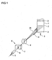
- Fig. 1 schematically shows in principle the process step of applying adhesive to a layer from which a honeycomb body is later to be produced together with other layers.
- a location especially one Layer 1, at least partially structured, with symbolically indicated structural extremes 2, that is to say structure minima and structure maxima, is moved in a direction of movement 3 relative to means 4 for applying adhesives.
- the means 4 for applying adhesive comprise a piezoelectric element 5, a nozzle 6, charging means 7, deflection means 8, and collecting means 9.
- the nozzle 6 is acted upon by the adhesive under a pressure of 2.5 bar or more.
- the nozzle 6 is set in motion by the piezoelectric element 5, to which a high-frequency AC voltage is applied. Vibration frequencies of more than 50 kHz, preferably more than 60 kHz, particularly preferably 100 kHz and more are preferred.
- Vibration frequencies of more than 50 kHz, preferably more than 60 kHz, particularly preferably 100 kHz and more are preferred.
- This drop jet 35 is electrostatically charged in the charging means 7.
- the drops of adhesive thus electrostatically charged are deflected by the deflecting means 8 by applying an electrostatic field.
- Fig. 1 the drop beam 35 is shown with different deflections. As a result, not only can adhesive points 10 be generated on the layer 1, but also adhesive lines 11.
- the adhesive ie the adhesive points 10 or adhesive lines 11, is applied directly adjacent to a structural extremum 2.
- the application of adhesive still lies in the area of the top of the structuring and not in the area of the side flank of the structuring, but directly adjacent to the structural extremum 2.
- the structural extremum 2 with which the at least partially structured layer 1 slides over the substantially smooth layer, is not provided with adhesive, so that the sliding friction is reduced in comparison to the winding with glue applied to the structural extreme 2.
- Fig. 2 shows schematically another embodiment of the means 4 for applying adhesive.
- an essentially smooth layer 12 is moved past a printing device 13 in the direction of movement 3, by means of which adhesive means 36 in the form of a drop jet 35 are applied in an application direction 41.
- the application direction 41 is essentially perpendicular to the direction of movement 3 of the layer 12.
- the printing device 13 comprises a piezoelectric element 5, charging means 7, deflection means 8 and collecting means 9.
- the piezoelectric element 5 is operated with a high-frequency alternating voltage which leads to an oscillation of the piezoelectric Element 5 leads in the direction of vibration 14.
- adhesive is supplied from an adhesive reservoir 16 through supply means 40 under high pressure to a nozzle 6.
- the vibrations of the piezoelectric element 5 produce a high-frequency continuous or quasi-continuous drop jet 35 therefrom. These drops 35 are electrostatically charged in the charging means 7 and deflected electrostatically in the deflecting means 8.
- Fig. 2 the drop beam 35 is shown with different deflections. The deflection takes place by applying respective voltages to the deflecting means 8 and the charging means 7. This allows the drop jet 35 to be moved relative to the position 1, 12.
- adhesive lines 11 are produced on an essentially smooth sheet-metal layer 12, which is shown in perspective. Here, very different lengths of the adhesive lines 11 can be generated.
- the drops of adhesive agent collected in the collecting means 9 are returned to the adhesive agent reservoir 16 via the return means 18 and possibly filters 19.
- the example shown is essentially a means 4 for applying adhesive, which works according to the continuous inkjet method.
- the second exemplary embodiment shown is a printing device 13 which works according to the drop-on-demand system. With such a system, no continuous high-frequency oscillation of a nozzle and thus a quasi-continuous drop jet is generated, rather individual drops 22 are generated by individual pulses.
- the same printing device 13 is shown at different times 1 to 4.
- the printing device 13 comprises a piezoelectric element 5, which can be provided with an electrical voltage pulse via contacts 20. The generation of drops is shown schematically at four different times 1 to 4. At time 1, the piezoelectric element 5 is in the rest position.
- Nozzle 6 and feed line 21 are filled with adhesive 36.
- a voltage pulse is applied to the piezoelectric element 5 via the contacts 20, which leads to a deflection of the piezoelectric element 5. This causes the adhesive 36 to move as symbolized by the two arrows.
- the voltage pulse in the piezoelectric element 5 is reduced again, so that it has already at least partially deformed back. This leads to a movement of the adhesive 36, as indicated by arrows.
- a drop 22 is ejected, which, however, has not yet been separated from the adhesive 36 in the nozzle 6. This takes place only in step 4, in which the piezoelectric element 5 is again in the rest position as at time 1.
- a detached Adhesive droplet 22 leaves the nozzle 6.
- Another method is the bubble jet method, in which a boiling film of the adhesive 36 is produced by briefly heating the nozzle 6. This creates a vapor bubble that throws a drop 22 of adhesive 36 out of the nozzle 6.
- the method is known from the prior art and at the same time represents a drop-on-demand method.
- Fig. 4 shows schematically the details of an adhesive application of a preferred embodiment of the method according to the invention.
- adhesive in the form of adhesive drops 22 is applied to an at least partially structured layer 1.
- the at least partially structured layer 1 is sinusoidal in the present example, but triangular waves or other structures could just as easily be present.
- the adhesive 4 is applied to the at least partially structured layer 1 by the means 4 for applying adhesive.
- the adhesive is applied in regions that are adjacent to structure extreme 2. If a honeycomb body is constructed from at least partially structured sheet metal layers 1 and possibly essentially smooth layers 12, the layers 1, 12 will move relative to one another when the layers 1, 12 are wound or twisted. This leads to the at least partially structured layers 1 slipping on the substantially smooth Layers 12.
- At least partially structured layers 1 and essentially smooth layers 12 must be connected to one another in order to build up a honeycomb body. This is often done by soldering, more precisely brazing, the layers to one another. The soldering takes place in the area of the structure extrema 2, so that when the at least partially structured layer 1 and the essentially smooth layer 12 come into contact, essentially triangular solder gussets form on both sides of the structure extremum 2.
- one of the great advantages of the present invention is that an adhesive can be applied directly adjacent to the structural extremes 2. This means that on the one hand the sliding friction between the layers 1, 12 is reduced during winding or twisting and on the other hand a soldering agent can be applied in the area of the extreme structure. A permanent and high-quality connection of the layers 1, 12 to one another can thus be established without the winding or twisting being made more difficult.
- the adhesive is applied directly adjacent to the structural extremes 2 in the manner according to the invention.
- Fig. 5 shows an example of two connected layers 1, 12.
- an at least partially structured layer 1 is connected to an essentially smooth layer 12.
- the at least partially structured layer 1 has structural extremes 2 against which the at least partially structured layer 1 bears against the essentially smooth layer 12.
- Processes were formed by soldering gussets 23 which connect the at least partially structured layer 1 to the substantially smooth layer 12.
- Fig. 6 shows schematically a structure of a device for producing honeycomb bodies.
- Fig. 6 shows means 23 for providing at least one at least partially structured metallic layer and possibly at least one essentially smooth metallic layer. These means can, for example, carry out the unwinding and severing, as well as, if necessary, structuring sheet metal layers of coils from smooth sheet metal foils, or they can also be made up according to fiber material, that is to say provide at least a certain length and, if necessary, structuring. These means 23 provide the required at least partially structured layers or, if necessary, essentially smooth layers.
- the means can have structuring means, which are not shown, by means of which an essentially structured layer is generated from a smooth layer, which is unwound, for example, from a coil.
- microstructuring means can be formed which form microstructures in the essentially smooth position.
- means 4 for applying adhesive are formed.
- stacking means 24 in which stacks are formed from essentially smooth and at least partially structured sheet metal layers.
- twisting means 25 in which one or more stacks produced in the stacking means 24 are twisted together.
- honeycomb bodies can be produced that have an S or involute shape. It is just as well possible not to form stacking means 24 and instead an at least partially structured layer or also at least partially structured layers and to wind up essentially smooth layers, for example to form a spiral honeycomb body.
- Soldering means 26 adjoin the twisting means 25, in which powdered solder is introduced into the wound honeycomb body.
- the soldering agent is followed by treatment agent 27, in which a thermal treatment is carried out, in which the solder introduced melts and connects the layers 1, 12 to one another.
- the individual means 23, 4, 24, 25, 26, 27 are connected to one another by connecting means 28, which enable the raw products to be transported from one means to the next.
- solder is applied in the soldering means 26 after stacking and twisting in the stacking means 24 and twisting means 25.
- Fig. 7 shows the example of a spirally wound honeycomb body different ways of applying adhesive 36, which are possible by means of the inventive method.
- the spirally wound honeycomb body 29 is spirally wound from an at least partially structured layer 1 and an essentially smooth layer 12.
- the honeycomb body 29 has channels 30 which extend through the honeycomb body 29.
- a first end face 37 can flow through the honeycomb body 29 to a second end face 38 in a flow direction 39.
- Fig. 7 shows various possibilities of how, according to the method according to the invention, an adhesive can be applied both to the at least partially structured layer 1 and to the essentially smooth layer 12.
- the adhesive 36 can be applied as an adhesive strip 31 on the end face or as an internal adhesive strip 32.
- the adhesive 36 is applied both to the at least partially structured layer 1 and to the substantially smooth layer Layer 12 continuous adhesive strips 33 can be formed. It is particularly preferred here to form them directly adjacent to the structure extremes 2 of the at least partially structured layer 1. In this case, the area of the structure which corresponds to the structure extremum 2 is not provided with adhesive 36. Furthermore, it is possible to provide only partial areas of the at least partially structured layer 1 with adhesive. Here, partial areas 34 can be formed in the flow direction with adhesive 36, which can be formed both on the end face and on the inside. Thus, several areas can be formed with adhesive 36 per structure. In all of these examples, the adhesive is applied according to the invention in the form of drops, preferably in the form of a drop jet, by means of a printing device such as, for example, a continuous inkjet printing device.
- a printing device such as, for example, a continuous inkjet printing device.
- solder powder When the solder powder is applied later, it adheres to the sections 31, 32, 33, 34 to which the adhesive 36 has been applied, so that the layers 1, 12 are connected to one another in these sections 31, 32, 33, 34.
- Fig. 8 shows another example of an advantageous embodiment of the method according to the invention.
- adhesive in the form of adhesive drops 22 is applied to an at least partially structured layer 1.
- the adhesive is applied essentially perpendicular to the surface 42 of the partial areas 43 to be provided with adhesive 36. That is, the adhesive is applied in a direction that is essentially the surface normal of the surface 42 to be provided with adhesive. This is done by a corresponding adjustment of the printing devices 13.
- the partial areas 42 to be provided with adhesive 36 are adjacent to the structural extremes 2.
- honeycomb bodies 29 advantageously allow very precise adhesive agents 36 to be applied to the areas in which a connection to adjacent layers is to be made later.
- adhesive 36 is applied by means of a printing technique, in particular also on the flank areas which are directly adjacent to an extreme structure 2.
- honeycomb bodies 29 which have a flexibility which is inhomogeneous across the flow direction 39 and / or essentially transverse to the flow direction 39.
Description
Die vorliegende Erfindung betrifft ein Verfahren zum Auftragen von Haftmittel auf Lagen zur Herstellung von Wabenkörpern, wie sie insbesondere als Katalysator-Trägerkörper, Adsorber und/oder Filterkörper im Automobilbau eingesetzt werden.The present invention relates to a method for applying adhesive to layers for the production of honeycomb bodies, such as are used in particular as catalyst support bodies, adsorbers and / or filter bodies in automobile construction.
Aus Lagen, insbesondere metallischen Lagen gewickelte oder geschichtete und verwundene Wabenkörper sind in vielfältigen Formen bekannt. Man unterscheidet vor allem zwei typische Bauformen für aus Lagen aufgebaute Wabenkörper. Eine frühe Bauform, für die die
Um einen Wabenkörper herzustellen, müssen diese Lagen miteinander verbunden werden. Hierzu sind verschiedene Verbindungstechniken möglich. Am Markt große Bedeutung haben Hartlötverfahren gewonnen, bei denen die Lagen zumindest in Teilbereichen miteinander hartgelötet werden. Hierzu ist es erforderlich, ein zusätzliches Material, das Lotmaterial, welches einen niedrigeren Schmelzpunkt als die Lagen aufweist, in den Wabenkörper einzubringen. Durch Erhitzen des Wabenkörpers über den Schmelzpunkt des Lotmaterials schmilzt das Lot auf und verbindet bei Abkühlung die Lagen miteinander.In order to produce a honeycomb body, these layers must be connected to one another. Various connection techniques are possible for this. Brazing processes in which the layers are brazed together, at least in some areas, have gained great importance on the market. This is it required to introduce an additional material, the solder material, which has a lower melting point than the layers, into the honeycomb body. By heating the honeycomb body above the melting point of the solder material, the solder melts and connects the layers to one another when it cools down.
Das Lotmaterial kann in unterschiedlichen Formen in den Wabenkörper eingebracht werden, beispielsweise als Lotfolie oder Lotpulver. Lotfolie wird in den Bereichen, in denen Lagen miteinander verbunden werden sollen, eingelegt oder -geklebt, während Lotpulver entweder ohne ein Haftmittel in den Wabenkörper eingebracht oder mittels eines Haftmittels in bestimmten Teilbereichen des Wabenkörpers aufgetragen wird.The solder material can be introduced into the honeycomb body in different forms, for example as a solder foil or solder powder. Solder foil is inserted or glued in the areas in which layers are to be connected to one another, while solder powder is either introduced into the honeycomb body without an adhesive or is applied in certain partial areas of the honeycomb body by means of an adhesive.
Wird das Lotpulver ohne Haftmittel in den Wabenkörper eingebracht, ist es praktisch nicht möglich, nur bestimmte, beispielsweise axial beabstandete Teilbereiche der Lagen miteinander zu verbinden. Wird eine lokal inhomogene Verbindung der Lagen untereinander, dass heißt eine Verbindung, die in Strömungsrichtung und/oder im wesentlichen quer zur Strömungsrichtung nicht durchgängig ist, oder auch der Lagen mit einem den Wabenkörper umschließenden Mantelrohr gewünscht, so ist bei Verwendung von Lotpulver das Auftragen eines Haftmittels nötig.If the solder powder is introduced into the honeycomb body without adhesive, it is practically not possible to connect only certain, for example axially spaced, partial areas of the layers to one another. If a locally inhomogeneous connection of the layers to one another, i.e. a connection that is not continuous in the direction of flow and / or essentially transversely to the direction of flow, or also the layers with a jacket tube enclosing the honeycomb body, the application of a solder powder is desirable Adhesive necessary.
Zum Auftragen des Haftmittels sind verschiedene Techniken bekannt. Beispielsweise offenbart die
Beide hier beschriebenen Verfahre weisen Nachteile auf. So ist der Auftrag des Haftmittels mittels Walzen relativ aufwendig, zudem ist insbesondere die relative Positionierung der Walzen in Bezug auf die mit Haftmittel zu versehenden Lagen fehleranfällig. Weiterhin erlaubt die Einbringung des Haftmittels mittels Kapillarkräften keine selektive Verbindung von benachbarten Lagen nur in Teilbereichen in einem genügend flexiblen Masse.Both of the methods described here have disadvantages. The application of the adhesive by means of rollers is relatively complex, and the relative positioning of the rollers in relation to the layers to be provided with adhesive is particularly prone to errors. Furthermore, the introduction of the adhesive by means of capillary forces does not allow a selective connection of adjacent layers only in partial areas in a sufficiently flexible mass.
Aus der
Die auf einem anderen technischen Gebiet liegende
Hiervon ausgehend ist es Aufgabe der vorliegenden Erfindung, ein Verfahren zum Auftragen von Haftmittel auf Lagen zur Herstellung von Wabenkörpern bereitzustellen, bei dem/der eine Verbindung der Lagen auf einfache Weise auch in Teilbereichen der Lagen erfolgen kann.Proceeding from this, it is an object of the present invention to provide a method for applying adhesive to layers for the production of To provide honeycomb bodies in which the layers can be connected in a simple manner even in partial areas of the layers.
Diese Aufgabe wird gelöst durch das Verfahren mit den Merkmalen des unabhängig formulierten Verfahrensanspruchs. Vorteilhafte Weiterbildungen sind Gegenstand der jeweiligen abhängigen Ansprüche, wobei die dort aufgeführten Merkmale in beliebiger, technisch sinnvoller Weise miteinander kombiniert werden können und weitere Ausgestaltungen der Erfindung aufzeigen.This object is achieved by the process with the features of the independently formulated process claim. Advantageous further developments are the subject of the respective dependent claims, the features listed there being able to be combined with one another in any technically meaningful manner and showing further refinements of the invention.
Das erfindungsgemäße Verfahren zum Auftragen von Haftmittel auf Lagen zur Herstellung eines Wabenkörpers, bevorzugt auf zumindest teilweise metallische Lagen, umfasst die folgenden Schritte:
- a) Bereitstellen von mindestens einer zumindest teilweise strukturierten Lage und gegebenenfalls von mindestens einer im wesentlichen glatten Lage;
- b) Auftragen von Haftmittel zumindest auf wenigstens einen Teilbereich der im wesentlichen glatten und/oder der zumindest teilweise strukturierten Lage;
- c) Herstellung eines Wabenkörpers;
- e) Durchführung eines thermischen Behandlungsschrittes,
- a) providing at least one at least partially structured layer and optionally at least one essentially smooth layer;
- b) applying adhesive to at least a portion of the substantially smooth and / or the at least partially structured layer;
- c) production of a honeycomb body;
- e) carrying out a thermal treatment step,
Insbesondere umfasst der Schritt c) das Stapeln mindestens einer zumindest teilweise strukturierten und mindestens einer im wesentlichen glatten Lage zu mindestens einem Stapel.In particular, step c) comprises stacking at least one at least partially structured and at least one essentially smooth layer to form at least one stack.
Dabei ist es bevorzugt, dass ein Schritt d) das Verwinden des mindestens einen Stapels von Lagen und/oder Aufwickeln mindestens einer zumindest teilweise strukturierten Lage und gegebenenfalls mindestens einer im wesentlichen glatten Lage zu einem Wabenkörper umfasst.It is preferred that step d) comprises twisting the at least one stack of layers and / or winding up at least one at least partially structured layer and optionally at least one essentially smooth layer to form a honeycomb body.
Weiter wird auch vorgeschlagen, dass der Wabenkörper nach Schritt b) und vor Schritt e) mit pulverförmigem Lotmaterial versehen wird. Auch der Auftrag des Lotmaterials in flüssiger Form, insbesondere in Tropfenform ist erfindungsgemäß möglich. Bevorzugt ist hierbei, dass die Tropfen von Lotmaterial die Tropfen Haftmittel auf den Lagen zumindest teilweise überdecken, bevorzugt möglichst großflächig überdecken. Es ist ferner auch möglich, im Schritt b) statt einem reinen Haftmittel eine Lotpaste, insbesondere eine Mischung von pulverförmigem Lotmaterial und einem viskosen Haftmittel, in Tropfenform aufzutragen.It is also proposed that the honeycomb body be provided with powdered solder material after step b) and before step e). The application of the solder material in liquid form, in particular in drop form, is also possible according to the invention. It is preferred here that the drops of solder material at least partially cover the drops of adhesive on the layers, preferably cover as large an area as possible. It is also possible in step b) to apply a solder paste, in particular a mixture of powdered solder material and a viscous adhesive, in drop form instead of a pure adhesive.
Der Auftrag des Haftmittels in Tropfenform hat den Vorteil, dass dieser kontaktfrei erfolgen kann, d. h. ohne dass es zu einem mechanischen Kontakt zwischen den Mitteln zum Auftragen des Haftmittels und den Lagen kommen muss. Zum anderen erfolgt erfindungsgemäß der Auftrag des Haftmittels vor dem Wickeln oder Stapeln der Lagen, so dass es in vorteilhafter Weise möglich ist, nur Teilbereiche der Lagen mit Haftmittel zu versehen und später miteinander zu verbinden. So ist es möglich, Wabenkörper aufzubauen, die in einigen Teilbereichen miteinander verlötet sind, während sie in anderen Teilbereichen nicht miteinander verlötet sind, so dass also Wabenkörper mit inhomogener Verbindung in einfacher Weise realisiert werden können. So können in vorteilhafter Weise Wabenkörper hergestellt werden, die in Bezug auf ihre Elastizität inhomogen sind, also Teilbereiche aufweisen, die elastischer oder weniger elastisch als andere Teilbereiche sind. Beim Einsatz des Wabenkörpers im Abgassystem eines Kraftfahrzeugs können so Wabenkörper hergestellt werden, die an die speziellen Anforderungen eines bestimmten Abgassystems angepasst sind.The application of the adhesive in droplet form has the advantage that it can take place without contact, ie without mechanical contact between the means for applying the adhesive and the layers. On the other hand, according to the invention, the adhesive is applied before the layers are wound or stacked, so that it is advantageously possible to provide only partial areas of the layers with adhesive and to bond them together later. It is thus possible to construct honeycomb bodies which are soldered to one another in some subregions, while they are not soldered to one another in other subregions, so that honeycomb bodies with an inhomogeneous connection can be realized in a simple manner. In this way, honeycomb bodies can be produced in an advantageous manner that are inhomogeneous with regard to their elasticity, that is to say they have partial areas that are more elastic or less elastic than other partial areas. When the honeycomb body is used in the exhaust system of a motor vehicle, honeycomb bodies can be produced in this way that are adapted to the special requirements of a particular exhaust system.
Weiterhin erlaubt der Auftrag des Haftmittels in Tropfenform eine örtliche Genauigkeit des Haftmittelauftrags, die zumindest in der Größenordnung der Tropfendurchmesser liegt, so dass eine örtlich sehr genaue Begrenzung der Teilbereiche der Lagen, auf die Haftmittel aufgetragen wird, erreicht werden kann.Furthermore, the application of the adhesive in drop form permits a local accuracy of the adhesive application, which is at least in the order of magnitude of the drop diameter, so that a locally very precise limitation of the partial areas of the layers to which adhesive is applied can be achieved.
Bei der Durchführung des thermischen Behandlungsschrittes kann es sich um einen Lötvorgang in einem Lötofen handeln, jedoch ist es genauso möglich, ein Aufheizen durch induktives Löten oder Strahlungslöten oder auch durch die Abwärme eines Schweißvorgangs zu erreichen.The thermal treatment step can be carried out by a soldering process in a soldering furnace, but it is also possible to achieve heating by inductive soldering or radiation soldering or also by the waste heat of a welding process.
Bei den verwendeten Haftmitteln handelt es sich bevorzugt um dünnflüssige Haftkleber, bevorzugt auf Basis eines polarisierbaren Lösungsmittels, insbesondere Wasser oder organische Lösungsmittel. Bevorzugt ist auch der Einsatz von bekannten und bewährten Haftmitteln zum Aufbau von Wabenkörpern.The adhesives used are preferably low-viscosity pressure-sensitive adhesives, preferably based on a polarizable solvent, in particular water or organic solvents. It is also preferred to use known and proven adhesives to build honeycomb bodies.
Gemäß einer vorteilhaften Ausgestaltung des Verfahrens wird das Haftmittel auf einer zumindest teilweise strukturierten Lage im Bereich der Flanken der Strukturierungen, bevorzugt nahe einem Strukturextremum aufgetragen.According to an advantageous embodiment of the method, the adhesive is applied to an at least partially structured layer in the region of the flanks of the structuring, preferably close to an extreme structure.
Wird beispielsweise ein Wabenkörper durch Wickeln einer im wesentlichen glatten und einer zumindest teilweise strukturierten Lage aufgebaut, so liegen nach dem Wickeln die Strukturextrema, also Strukturminima und Strukturmaxima, der zumindest teilweise strukturierten Lage an entsprechenden Bereichen der im wesentlichen glatten Lagen an. Die Anlageflächen bilden die Kontaktbereiche zwischen den Lagen, in denen später eine Lötverbindung ausgebildet werden soll. Dies erfolgt durch Einbringen von Lotpulver in der Nähe der Strukturextrema, so dass sich beim Löten mindestens einer, bevorzugt zwei Lötzwickel benachbart zu den Strukturextrema ausbilden. Diese Lötzwickel können beispielsweise näherungsweise dreiecksförmig sein. Wird das Haftmittel vor dem Wickeln bzw. Verwinden der Lagen und das Lotmittel nach dem Wickeln bzw. Verwinden der Lagen in den Wabenkörper eingebracht, so bilden sich Lötzwickel direkt benachbart zu den Strukturextrema aus, während das Strukturextremun selbst jedoch nicht zur Lötverbindung zwischen den Lagen beiträgt.If, for example, a honeycomb body is built up by winding an essentially smooth and an at least partially structured layer, the structural extremes, i.e. structure minima and structure maxima, of the at least partially structured layer rest on corresponding areas of the essentially smooth layers after the winding. The contact surfaces form the Contact areas between the layers in which a solder connection is to be formed later. This is done by introducing solder powder in the vicinity of the structural extremes, so that at least one, preferably two, solder gussets form adjacent to the structural extremes during soldering. These solder gussets can be approximately triangular, for example. If the adhesive is introduced into the honeycomb body before the winding or twisting of the layers and the solder after winding or twisting of the layers, then solder gussets form directly adjacent to the structural extremes, while the structural extremity itself does not contribute to the solder connection between the layers ,
Wird nun das Haftmittel auf die Flanken der Strukturierungen nahe einem Strukturextremum aufgetragen, so erfolgt einerseits bei Belotung ein Anhaften des Lotpulvers genau in den Bereichen, die später verbunden werden sollen und andererseits erfolgt kein Haftmittelauftrag auf dem Strukturextremum selber. Beim Aufwickeln des Wabenkörpers oder auch beim Verwinden von einem oder mehreren Stapeln von Lagen kommt es zu Relativbewegungen zwischen der im wesentlichen glatten und der zumindest teilweise strukturierten Lage. Hierbei gleiten die beiden Lagen im wesentlichen auf den Strukturextrema. Liegt nun auf dem Strukturextremum Leim auf, so wird diese Relativbewegung behindert und dadurch das Wickeln bzw. Verwinden erschwert. Somit bedingt ein Auftrag des Haftmittels auf den Flanken der Strukturierung eine verbesserte Wickel- bzw. Verwindungsfähigkeit, wobei die Anbindung der Lagen aneinander trotzdem mit hoher Zuverlässigkeit erreicht wird.If the adhesive is now applied to the flanks of the structuring near an extreme structure, the solder powder adheres precisely in the areas that are to be joined later, on the one hand, and on the other hand no adhesive is applied to the extreme structure itself. When winding up the honeycomb body or also when twisting one or more stacks of layers, there are relative movements between the essentially smooth and the at least partially structured layer. The two layers essentially slide onto the extreme structure. If there is glue on the extreme structure, this relative movement is hindered and the winding or twisting is made more difficult. Applying the adhesive to the flanks of the structuring thus results in improved winding or twisting capability, the bonding of the layers to one another nevertheless being achieved with high reliability.
Gemäß dem erfindungsgemäßen Verfahren wird das Haftmittel aufgedruckt nämlich nach einem Drop-on-Demand-Verfahren, einem Bubble-Jet-Verfahren und/oder einem Continuous-Inkjet-Verfahren.According to the method according to the invention, the adhesive is printed namely using a drop-on-demand method, a bubble jet method and / or a continuous inkjet method.
Drop-on-Demand-Verfahren sind Druckverfahren, die sich dadurch auszeichnen, dass ein Tropfen des Haftmittels nur dann erzeugt wird, wenn ein bestimmter Punkt der Lagen bedruckt werden soll. Betrachtet man eine Druckeinrichtung, die einen Haftmitteltropfen emittieren kann und den entsprechenden Bereich der Lage, auf welcher dieser Haftmitteltropfen aufgetragen werden kann, so wird also ein Haftmitteltropfen nur dann erzeugt, wenn der entsprechende Bereich der Lage mit Haftmittel versehen werden soll. Soll kein Haftmittel aufgetragen werden, wird auch kein Haftmitteltropfen erzeugt.Drop-on-demand processes are printing processes which are characterized by the fact that a drop of the adhesive is only generated when a specific point on the layers is to be printed. If one considers a printing device which can emit an adhesive drop and the corresponding area of the layer on which this adhesive drop can be applied, an adhesive drop is only generated when the corresponding area of the layer is to be provided with adhesive. If no adhesive is to be applied, no adhesive drop is generated.
Im Gegensatz dazu existieren auch kontinuierliche Druckverfahren, bei denen ein kontinuierlicher Strahl von Haftmitteltropfen erzeugt wird, der dann, wenn ein Bereich nicht bedruckt werden soll, über eine Ablenkung in ein Auffangmittel geführt wird und dann nicht auf die zu bedruckende Oberfläche gelangt.In contrast to this, there are also continuous printing processes in which a continuous jet of adhesive drops is generated which, if an area is not to be printed, is deflected into a collecting medium and then does not reach the surface to be printed.
Bei Drop-on-Demand-Systemen ist es beispielsweise möglich, einzelne Tropfen des Haftmittel mittels piezoelektrischer Aktoren zu erzeugen. Bei piezoelektrischen Aktoren handelt es sich um elektromechanische Wandler, die auf dem piezoelektrischen Effekt beruhen. Hierbei führt die Anlage einer Wechselspannung an das piezoelektrische Element zu mechanischen Schwingungen. Wird als piezoelektrischer Wandler eine Düse betrieben, die mit dem zu druckenden Stoff beaufschlagt ist, so entstehen durch diese mechanischen Schwingungen Tropfen des zu druckenden Materials, die die Düse mit einer relativ hohen Geschwindigkeit verlassen. Diese Tropfen treffen auf das zu bedruckende Material auf und bleiben dort haften. Durch Positionierung der Druckeinrichtung, die beispielsweise die eben beschriebenen piezoelektrischen Aktor enthält, ist es möglich, bestimmte Teilbereiche der Lage zu bedrucken und bestimmte Teilbereiche nicht zu bedrucken. Es sind mehrere Drop-on-Demand-Verfahren bekannt, die auf piezoelektrischen Wandlern beruhen. Nur als Beispiele seien Piezoröhrchen, Piezoscheiben, und Piezolamellen erwähnt.With drop-on-demand systems, for example, it is possible to generate individual drops of the adhesive using piezoelectric actuators. Piezoelectric actuators are electromechanical transducers based on the piezoelectric effect. The application of an AC voltage to the piezoelectric element leads to mechanical vibrations. If, as a piezoelectric transducer, a nozzle is operated which has the substance to be printed on, the mechanical vibrations cause drops of the material to be printed which leave the nozzle at a relatively high speed. These drops hit the material to be printed and stick there. By positioning the printing device, which contains, for example, the piezoelectric actuator just described, it is possible to print on certain partial areas of the layer and not on certain partial areas. There are several drop-on-demand processes known that are based on piezoelectric transducers. Piezo tubes, piezo disks and piezo plates are only examples.
Ein weiteres Drop-on-Demand-Verfahren stellt das Bubble-Jet-Verfahren dar. Hierbei werden die Haftmitteltropfen nicht mittels eines piezoelektrischen Wandlers erzeugt, sondern durch Einsatz von thermischen Aktoren. Es handelt sich hierbei um Heizelemente, die in einer Düse ausgebildet sind, die mit dem zu druckenden Material, also dem Haftmittel, beaufschlagt sind. Durch diese Heizelemente wird kurzzeitig in der Düse lokal eine Temperatur erzeugt, die deutlich über der Siedetemperatur des Haftmittels ist. Das Haftmittel beginnt lokal als Film zu sieden, worauf sich nach kurzer Zeit eine geschlossene Dampfblase bildet. Diese Dampfblase treibt einen Tropfen des zu druckenden Stoffes aus der Düse, wobei Drücke von 10 bar oder mehr und Austrittsgeschwindigkeiten von 10 m/sec und mehr erreicht werden können. Die Dampfblase kollabiert daran anschließend, worauf es aufgrund der Kapillarkräfte zum Nachsaugen von Haftmittel kommt. Bei solchen Bubble-Jet-Verfahren werden verschiedene Drucktechniken unterschieden, die allgemein als Edge- und Sideshooter bekannt sind.Another drop-on-demand process is the bubble jet process. Here, the adhesive drops are not generated by means of a piezoelectric transducer, but by using thermal actuators. These are heating elements which are formed in a nozzle and which are acted upon by the material to be printed, that is to say the adhesive. These heating elements briefly generate a temperature locally in the nozzle that is significantly above the boiling point of the adhesive. The adhesive begins to boil locally as a film, after which a closed vapor bubble forms after a short time. This vapor bubble drives a drop of the substance to be printed out of the nozzle, whereby pressures of 10 bar or more and outlet speeds of 10 m / sec and more can be achieved. The vapor bubble then collapses, resulting in the suction of adhesive due to the capillary forces. In such a bubble jet process, a distinction is made between different printing techniques, which are generally known as edge and side shooters.
Bei dem Continuous-Inkjet-Verfahren handelt es sich um ein bekanntes Druckverfahren, bei dem ein kontinuierlicher Strahl von Tintentropfen erzeugt wird, welcher durch Positionierung des Druckkopfes und/oder elektrostatische Auslenkung ein Druck in vorbestimmten Teilbereichen erfolgt.The continuous inkjet method is a known printing method in which a continuous jet of ink drops is generated, which is printed by positioning the printhead and / or electrostatic deflection in predetermined partial areas.
Wenn ein solches Continuous-Inkjet-Verfahren zum Auftragen von Haftmittel verwendet wird, wird ein kontinuierlicher Strahl von Haftmitteltropfen erzeugt, der auf die mit Haftmittel zu versehenden Teilbereiche der Lagen gelenkt wird. Die Haftmitteltropfen bleiben daraufhin an der Lage haften. Insbesondere die elektrostatische Auslenkung erlaubt in vorteilhafter Weise nicht nur das Drucken von Punkten, sondern auch das Drucken von sich überlappenden Punkten, die im Idealfall Linien bilden.If such a continuous inkjet method is used to apply adhesive, a continuous jet of adhesive drops is generated which is directed onto the partial regions of the layers to be provided with adhesive. The drops of adhesive then adhere to the layer. In particular, the electrostatic deflection advantageously not only allows printing of dots, but also the printing of overlapping dots, which ideally form lines.
Gemäß einer vorteilhaften Ausgestaltung des Verfahrens wird das Haftmittel durch eine Düse appliziert, welche impulsangeregt wird. Impulsangeregt bedeutet in diesem Zusammenhang, dass keine hochfrequente Schwingung der Düse erzeugt wird sondern diese vielmehr dann, wenn ein Haftmitteltropfen durch die Düse ausgestoßen werden soll, die Düse über einen einzelnen Impuls angeregt wird. Eine solche Impulsanregung kann beispielsweise durch einen elektrischen Spannungspuls an einem mit der Düse verbundenen piezoelektrischen Element oder durch einen Wärmeimpuls an ein entsprechendes Heizelement erzeugt werden. Bei einer Impulsanregung erfolgt also eine Anregung der Düse nur dann, wenn ein Haftmitteltropfen zum Auftrag auf die Lage benötigt wird.According to an advantageous embodiment of the method, the adhesive is applied through a nozzle, which is excited by pulses. In this context, pulse-excited means that no high-frequency oscillation of the nozzle is generated, but rather, if an adhesive drop is to be expelled through the nozzle, the nozzle is excited by a single pulse. Such pulse excitation can be generated, for example, by an electrical voltage pulse on a piezoelectric element connected to the nozzle or by a heat pulse on a corresponding heating element. In the case of impulse excitation, the nozzle is only excited when an adhesive drop is required to apply it to the layer.
Gemäß einer vorteilhaften Ausgestaltung des Verfahrens wird das Haftmittel durch eine Düse appliziert, welche zu hochfrequenten Schwingungen angeregt wird. Die Schwingungsanregung der Düse unterscheidet sich bei einem Continuous-Inkjet-Verfahren von einem Drop-on-Demand-Verfahren dadurch, dass diese Anregung beständig erfolgt, so dass ein kontinuierlicher Strahl von Haftmitteltropfen erzeugt wird. Sollen bestimmte Teilbereiche nicht bedruckt werden, auf die ohne weitere Maßnahmen nun der Haftmitteltropfenstrahl treffen würde, so muss durch Ablenkmittel gewährleistet sein, dass diese Haftmitteltropfen nicht die Lagen erreichen, sondern vorher abgefangen werden. Unter hochfrequenten Schwingungen sind insbesondere Schwingungen einer Frequenz von mehr als 10 kHz, bevorzugt mehr als 50 kHz, besonders bevorzugt 100 kHz und mehr zu verstehen.According to an advantageous embodiment of the method, the adhesive is applied through a nozzle which is excited to produce high-frequency vibrations. The vibration excitation of the nozzle differs in a continuous inkjet process from a drop-on-demand process in that this excitation takes place continuously, so that a continuous jet of adhesive drops is generated. If certain sub-areas are not to be printed on, which would now be hit by the adhesive drop jet without further measures, it must be ensured by means of deflecting means that these adhesive drops do not reach the layers but are intercepted beforehand. High-frequency vibrations are to be understood in particular as vibrations of a frequency of more than 10 kHz, preferably more than 50 kHz, particularly preferably 100 kHz and more.
Gemäß einer weiteren vorteilhaften Ausgestaltung des Verfahrens wird das Haftmittel in der Düse einen Druck von mehr als 2 bar, bevorzugt mehr als 2,5 bar auf.According to a further advantageous embodiment of the method, the adhesive in the nozzle is at a pressure of more than 2 bar, preferably more than 2.5 bar.
Gemäß einer weiteren vorteilhaften Ausgestaltung des Verfahrens erfolgt die Anregung der Düse mittels eines piezoelektrischen Elements. Hierbei erfolgt die Anregung über das piezoelektrische Element beispielsweise im Fall eines Drop-on-Demand-Systems über eine impulsartige Anregung des piezoelektrischen Elementes und im Falle eines Continuous-Inkjet-Verfahrens über eine dauerhafte hochfrequente Anregung des piezoelektrischen Elementes.According to a further advantageous embodiment of the method, the nozzle is excited by means of a piezoelectric element. In this case, the excitation takes place via the piezoelectric element, for example in the case of a drop-on-demand system, by means of a pulse-like excitation of the piezoelectric element and, in the case of a continuous inkjet method, by means of permanent high-frequency excitation of the piezoelectric element.
Gemäß einer vorteilhaften Ausgestaltung des Verfahrens erfolgt die Anregung bei einer Frequenz von mindestens 50 kHz, bevorzugt mindestens 60 kHz, besonders bevorzugt mindestens 100 kHz. Solche hochfrequenten Anregungen erlauben bei einem Continuous-Inkjet-System einen sehr schnellen und zügigen Auftrag des Haftmittels auf die zu verbindenden Bereiche der Lagen. So können hohe Fertigungsgeschwindigkeiten erreicht werden, die eine Fertigung eines Wabenkörpers bei sehr kurzer Taktzeit ermöglichen.According to an advantageous embodiment of the method, the excitation takes place at a frequency of at least 50 kHz, preferably at least 60 kHz, particularly preferably at least 100 kHz. With a continuous inkjet system, such high-frequency excitations allow the adhesive to be applied very quickly and quickly to the areas of the layers to be joined. In this way, high production speeds can be achieved, which enable the production of a honeycomb body with a very short cycle time.
Gemäß einer weiteren vorteilhaften Ausgestaltung des Verfahrens werden die Haftmitteltropfen elektrostatisch aufgeladen und elektrostatisch abgelenkt. So kann neben oder alternativ zu einer mechanischen Auslenkung des Druckkopfes noch eine Feinauslenkung des Strahls erfolgen, um besonders genau definierte Haftmittelaufträge zu erreichen.According to a further advantageous embodiment of the method, the drops of adhesive are electrostatically charged and electrostatically deflected. In addition to or as an alternative to a mechanical deflection of the printhead, a fine deflection of the jet can also take place in order to achieve particularly precisely defined adhesive applications.
Gemäß einer weiteren vorteilhaften Ausgestaltung des Verfahrens werden Haftmitteltropfen, die nicht auf die Lage aufgetragen werden sollen, elektrostatisch in ein Auffangmittel gelenkt und rückgeführt. In vorteilhafter Weise ist es so möglich, Tropfen, die nicht auf die Lagen aufgetragen werden sollen, abzulenken, aufzufangen und dann in ein Haftmittelreservoir rückzuführen. So kann in vorteilhafter Weise der Verbrauch von Haftmittel reduziert werden.According to a further advantageous embodiment of the method, drops of adhesive which are not to be applied to the layer are electrostatically directed into a collecting means and returned. Advantageously, it is possible to use drops that are not applied to the layers to distract, catch and then return to an adhesive reservoir. In this way, the consumption of adhesive can be reduced in an advantageous manner.
Gemäß einer vorteilhaften Ausgestaltung des Verfahrens wird die Positionierung des Haftmittels auf den Lagen zumindest zum Teil durch eine gezielte elektrostatische Ablenkung der Haftmitteltropfen vor Auftreffen auf die Lagen erreicht. Dies ermöglicht in vorteilhafter Weise eine sehr präzise Positionierung der Haftmitteltropfen auf der Lage. Ein reine Positionierung des Haftmittels auf den Lagen durch elektrostatische Ablenkung ist möglich und erfindungsgemäß. Eine solche kann sehr präzise und schnell erfolgen, so dass die Herstellung von Wabenkörpern in hoher Qualität bei kurzen Produktionszeiten möglich ist.According to an advantageous embodiment of the method, the positioning of the adhesive on the layers is achieved at least in part by a targeted electrostatic deflection of the adhesive drops before striking the layers. This advantageously enables the adhesive drops to be positioned very precisely on the layer. A pure positioning of the adhesive on the layers by electrostatic deflection is possible and according to the invention. This can be done very precisely and quickly, so that the production of honeycomb bodies in high quality is possible with short production times.
Gemäß einer weiteren vorteilhaften Ausgestaltung des Verfahrens werden die Haftmitteltropfen durch kurzzeitiges Erhitzen des Haftmittels über dessen Siedepunkt in einer Düse erzeugt. Das Haftmittel füllt hierbei eine dünne Düse kontinuierlich aus, ein kurzzeitiges Erhitzen über den Siedepunkt führt zur Entstehung einer Dampfblase, die einen Haftmitteltropfen aus der Düse herausschleudert. Dieser Haftmitteltropfen kann zum Auftrag des Haftmittels auf die Lage verwendet werden.According to a further advantageous embodiment of the method, the adhesive drops are generated by briefly heating the adhesive above its boiling point in a nozzle. The adhesive continuously fills a thin nozzle, briefly heating above the boiling point leads to the formation of a vapor bubble that throws a drop of adhesive out of the nozzle. This drop of adhesive can be used to apply the adhesive to the layer.
Gemäß einer weiteren vorteilhaften Ausgestaltung des Verfahrens ist zumindest ein Teil der Lagen als metallische Lagen, bevorzugt Blechlagen und/oder metallische Faserlagen ausgebildet. Der Aufbau von erfindungsgemäßen Wabenkörpern aus metallischen Lagen, insbesondere aus Blechlagen und/oder metallischen Faserlagen führt in vorteilhafter Weise zur Ausbildung von sehr dauerhaltbaren und hitzebeständigen Wabenkörpern. Diese können als Katalysator-Trägerkörper zur Umsetzung von zumindest Teilen des Abgases eines Automobils dienen. Weiterhin können solche Wabenkörper auch als Trägerstrukturen für Adsorberbeschichtungen verwendet werden, also beispielsweise der Speicherung von Kohlenwasserstoffen dienen oder im Abgassystem eines Automobils z. B. eine oder mehrere Komponenten des Abgases speichern und zu einem anderen Zeitpunkt wieder abgeben. Beispielsweise sind solche Adsorber zur zwischenzeitlichen Speicherung von Stickoxiden (NOx) bekannt. Ein weiteres Einsatzgebiet solcher Wabenkörper ist als Filterkörper im Automobilbau, beispielsweise zum Abfiltern von Partikeln. Solche Partikelfilter können offen oder geschlossen ausgebildet sein, wobei bei einem offenen Partikelfilter Teilchen, die größer sind als die Porengrößen der Filtermaterialien durch den Filter durchgehen können, während dies ist bei geschlossenen Filtersystemen nicht der Fall ist. Es ist auch möglich und erfindungsgemäß, metallische Faserlagen mit Blechstreifen zu verstärken.According to a further advantageous embodiment of the method, at least some of the layers are designed as metallic layers, preferably sheet metal layers and / or metallic fiber layers. The construction of honeycomb bodies according to the invention from metallic layers, in particular from sheet metal layers and / or metallic fiber layers, advantageously leads to the formation of very durable and heat-resistant honeycomb bodies. These can serve as a catalyst carrier body for converting at least parts of the exhaust gas of an automobile. Furthermore, such honeycomb bodies can also be used as support structures for adsorber coatings, that is serve for example the storage of hydrocarbons or in the exhaust system of an automobile z. B. save one or more components of the exhaust gas and release it at another time. For example, such adsorbers for the temporary storage of nitrogen oxides (NO x ) are known. Another area of application of such honeycomb bodies is as a filter body in automobile construction, for example for filtering off particles. Such particle filters can be designed to be open or closed, whereby in the case of an open particle filter particles which are larger than the pore sizes of the filter materials can pass through the filter, whereas this is not the case with closed filter systems. It is also possible and according to the invention to reinforce metallic fiber layers with sheet metal strips.
Gemäß einer weiteren vorteilhaften Ausgestaltung des erfindungsgemäßen Verfahrens ist zumindest ein Teil der Lagen aus Kompositmaterial, bevorzugt einem Kompositmaterial aus keramischen Fasern und metallischem Material, bevorzugt metallischen Fasern und/oder Blechlagen, ausgebildet. In vorteilhafter Weise ist es so möglich, Kompositmaterialien beispielsweise in Filterkörpern einzusetzen, die aus keramischen Fasern und/oder metallischen Fasern bestehen und die ggf. durch aufgebrachte und mit dem Fasermaterial verbundene Blechlagen verstärkt werden können. Genauso gut ist es möglich, einen Teilbereich der Lage aus einer Blechlage und einen anderen Teilbereich der Lage aus einer keramischen Faserlage auszubilden.According to a further advantageous embodiment of the method according to the invention, at least some of the layers are made of composite material, preferably a composite material made of ceramic fibers and metallic material, preferably metallic fibers and / or sheet metal layers. It is thus advantageously possible to use composite materials, for example in filter bodies, which consist of ceramic fibers and / or metallic fibers and which can optionally be reinforced by sheet metal layers applied and connected to the fiber material. It is equally possible to form a partial area of the layer from a sheet metal layer and another partial area of the layer from a ceramic fiber layer.
Gemäß einer vorteilhaften Ausgestaltung des Verfahrens weisen die Haftmitteltropfen auf der Lage einen mittleren Durchmesser von 0,05 bis 0,7 mm, bevorzugt von 0,1 bis 0,4 mm, besonders bevorzugt von 0,1 bis 0,3 mm auf. Haftmittelpunkte bzw. -linien auf der Lage, die einen solchen Durchmesser bzw. eine solche Breite aufweisen, ermöglichen eine sehr genaue Definition der Bereiche, in denen benachbarte Lagen nach dem Löten verbunden sind.According to an advantageous embodiment of the method, the adhesive drops on the layer have an average diameter of 0.05 to 0.7 mm, preferably 0.1 to 0.4 mm, particularly preferably 0.1 to 0.3 mm. Adhesive centers or lines on the layer which have such a diameter or width allow a very precise definition of the areas in which adjacent layers are connected after soldering.
Gemäß einer weiteren vorteilhaften Ausgestaltung des Verfahrens erfolgt das Auftragen des Haftmittels bevorzugt in einer Auftragrichtung, die im wesentlichen senkrecht zur Bewegungsrichtung der Lagen ist.According to a further advantageous embodiment of the method, the adhesive is preferably applied in an application direction which is essentially perpendicular to the direction of movement of the layers.
Gemäß einer weiteren vorteilhaften Ausgestaltung des Verfahrens erfolgt das Auftragen des Haftmittels bevorzugt in einer Auftragsrichtung, die im wesentlichen senkrecht zu einer Oberfläche des wenigstens einen mit Haftmittel zu versehenden Teilbereichs ist. Dies ermöglicht insbesondere bei Auftrag des Haftmittels auf die zumindest teilweise strukturierten Folien die Bildung von definierten Haftmitteltropfen benachbart zu den Strukturextrema, so dass das Auftragen einer breiten Haftmittelschicht auf den seitlichen Flanken verhindert werden kann.According to a further advantageous embodiment of the method, the adhesive is preferably applied in an application direction which is essentially perpendicular to a surface of the at least one partial area to be provided with adhesive. This allows, in particular when applying the adhesive to the at least partially structured foils, the formation of defined adhesive drops adjacent to the structural extremes, so that the application of a broad adhesive layer on the side flanks can be prevented.
Zudem wird nachfolgend eine Vorrichtung zum Herstellen von Wabenkörpern erläutert, die zumindest die folgenden Komponenten umfasst:
- a) Mittel zum Bereitstellen von mindestens einer zumindest teilweise strukturierten Lage und gegebenenfalls von mindestens einer im wesentlichen glatten Lage;
- b) Mittel zum Auftragen von Haftmittel zumindest auf wenigstens einen Teilbereich der im wesentlichen glatten und/oder der zumindest teilweise strukturierten Lage;
- c) Mittel zur Generierung eines Wabenkörpers;
- e) Belotungsmittel, mittels derer der Wabenkörper mit Lot versehen werden kann, welches im wesentlichen an den mit Haftmittel versehen Bereichen haften bleibt; und
- f) Behandlungsmittel zur Durchführung eines thermischen Behandlungsschrittes,
- a) means for providing at least one at least partially structured layer and optionally at least one substantially smooth layer;
- b) means for applying adhesive to at least a portion of the substantially smooth and / or the at least partially structured layer;
- c) means for generating a honeycomb body;
- e) soldering agent, by means of which the honeycomb body can be provided with solder, which essentially adheres to the areas provided with adhesive; and
- f) treatment agent for carrying out a thermal treatment step,
Insbesondere umfasst die Komponente c) Stapelmittel, mit denen mindestens eine zumindest teilweise strukturierte und mindestens eine im wesentlichen glatten Lage zu mindestens einem Stapel gestapelt werden.In particular, component c) comprises stacking means with which at least one at least partially structured and at least one essentially smooth layer is stacked to form at least one stack.
Bevorzugt ist zudem eine Komponente d) vorgesehen, die Verwindungsmittel zum Verwinden des mindestens einen Stapels von metallischen Lagen und/oder Aufwickelmittel zum Aufwickeln mindestens einer zumindest teilweise strukturierten Lage und gegebenenfalls mindestens einer im wesentlichen glatten Lage zu einem Wabenkörper umfasst.A component d) is preferably also provided, which comprises twisting means for twisting the at least one stack of metallic layers and / or winding means for winding up at least one at least partially structured layer and optionally at least one substantially smooth layer to form a honeycomb body.
Die Vorrichtung ermöglicht in vorteilhafter Weise das Auftragen von Haftmittel zur Fixierung von Lotmittel auf Lagen zum Aufbau eines Wabenkörpers mittels einer Drucktechnik. Hierbei kann mittels der Druckeinrichtung ein Auftrag von Haftmittel sowohl auf die im wesentlichen glatten, als auch auf die zumindest teilweise strukturierten Lagen erfolgen.The device advantageously enables the application of adhesive for fixing solder on layers for building up a honeycomb body by means of a printing technique. In this case, the pressure device can be used to apply adhesive to both the substantially smooth and the at least partially structured layers.
Unter Lagen sind hier insbesondere metallische Lagen und/oder Lagen aus Kompositmaterial zu verstehen.Layers are to be understood here in particular as metallic layers and / or layers made of composite material.
Gemäß einer vorteilhaften Ausgestaltung der erfindungsgemäßen Vorrichtung ist die Druckeinrichtung eine Drop-on-Demand-Druckeinrichtung.According to an advantageous embodiment of the device according to the invention, the printing device is a drop-on-demand printing device.
Gemäß einer weiteren vorteilhaften Ausgestaltung der Vorrichtung ist die Druckeinrichtung eine Bubble-Jet-Druckeinrichtung.According to a further advantageous embodiment of the device, the printing device is a bubble jet printing device.
Gemäß einer weiteren vorteilhaften Ausgestaltung der Vorrichtung ist die Druckeinrichtung eine Continuous-Inkjet-Druckeinrichtung.According to a further advantageous embodiment of the device, the printing device is a continuous inkjet printing device.
Alle diese drei Druckeinrichtungen erlauben prinzipiell in sehr einfacher Weise den Auftrag von Haftmittel. Bei den solchen Druckeinrichtungen zugrundeliegenden Druckverfahren handelt es sich um sogenannte Tinten- oder Tintenstrahlverfahren.In principle, all these three printing devices allow the application of adhesive in a very simple manner. The printing processes on which such printing devices are based are so-called ink or ink jet processes.
Gemäß einer weiteren vorteilhaften Ausgestaltung der Vorrichtung weist die Druckeinrichtung eine Düse zum Auftragen des Haftmittels auf, die zu hochfrequenten oder impulsartigen Schwingungen anregbar ist. Eine hochfrequent oder impulsartig angeregte Düse erlaubt in vorteilhafter Weise mit einer entsprechenden Druckeinrichtung die Erzeugung von einzelnen Haftmitteltropfen oder Haftmitteltropfstrahlen, die auf die zu bedruckenden Teilbereiche der metallischen Lagen aufgetragen werden können.According to a further advantageous embodiment of the device, the printing device has a nozzle for applying the adhesive, which nozzle can be excited to produce high-frequency or pulse-like vibrations. A high-frequency or pulse-like nozzle advantageously allows, with a corresponding printing device, the generation of individual adhesive drops or adhesive droplet jets which can be applied to the partial areas of the metallic layers to be printed.
Gemäß einer weiteren vorteilhaften Ausgestaltung der Vorrichtung weist die Düse ein piezoelektrisches Element auf. Ein piezoelektrisches Element ist ein Element, das nach dem piezoelektrischen Effekt arbeitet. D. h., eine an diesem Element anliegende elektrische Wechselspannung wird in Schwingungen umgewandelt. Hierbei kann entweder eine impulsartige Anregung durch einen Spannungsstoß erfolgen oder aber eine hochfrequente Schwingung erzeugt werden, indem eine hochfrequente Wechselspannung an das piezoelektrische Element angelegt wird.According to a further advantageous embodiment of the device, the nozzle has a piezoelectric element. A piezoelectric element is an element that works according to the piezoelectric effect. That is, an electrical AC voltage applied to this element is converted into vibrations. In this case, either a pulse-like excitation by a surge or a high-frequency oscillation can be generated by applying a high-frequency AC voltage to the piezoelectric element.
Gemäß einer weiteren vorteilhaften Ausgestaltung der Vorrichtung weist die Druckeinrichtung Auflademittel zur elektrostatischen Aufladung des Haftmittels und Ablenkmittel zur Ablenkung des Haftmittels auf.According to a further advantageous embodiment of the device, the printing device has charging means for electrostatically charging the adhesive and deflecting means for deflecting the adhesive.
Hierbei ist es besonders vorteilhaft, auch die Ablenkmittel in elektrostatischer Art und Weise auszubilden, also eine Ablenkung der elektrostatisch aufgeladenen Tropfen des Haftmittels durch ein elektrostatisches Feld zu erzeugen.It is particularly advantageous here to also design the deflecting means in an electrostatic manner, that is to say to generate a deflection of the electrostatically charged drops of the adhesive by means of an electrostatic field.
Gemäß einer weiteren vorteilhaften Ausgestaltung der Vorrichtung umfassen die Mittel zum Auftragen von Haftmittel Auffangmittel zum Auffangen nicht aufgetragenen Haftmittels.According to a further advantageous embodiment of the device, the means for applying adhesive comprise collecting means for collecting adhesive that has not been applied.
Im Falle eines Tintenstrahlverfahrens wie beispielsweise des Continuous-Inkjet-Verfahrens und entsprechend ausgebildeter Druckeinrichtungen ist es nötig, Haftmitteltropfen, die nicht auf die Oberfläche der metallischen Lagen gelangen sollen, aufzufangen. Beispielsweise ist es so möglich, nur bestimmte Teilbereiche einer Lage mit Haftmittel zu versehen. So könnte es beispielsweise vorteilhaft sein, die Flanken der Strukturen der zumindest teilweise strukturierten Lagen mit Haftmittel zu bedrucken. Hierzu wäre eine Druckeinrichtung vorteilhaft, deren Länge der Länge der Strukturen der zumindest teilweise strukturierten Lagen entspricht. Wenn nun nicht die Strukturen über die gesamte Länge bedruckt werden sollen, sondern nur in Teilbereichen, so ist es nötig, einige der Tropfen, die die Bereiche treffen würden, in denen kein Haftmittelauftrag nötig ist, aufzufangen. Dies geschieht mittels der Auffangmittel. Das aufgefangene Haftmittel wird gemäß einer weiteren vorteilhaften Ausgestaltung der Vorrichtung durch Rückführmittel, die in dem Mittel zum Auftragen von Haftmittel umfasst sind, zum Haftmittelreservoir zurückgeführt.In the case of an inkjet method such as the continuous inkjet method and appropriately trained printing devices, it is necessary to collect drops of adhesive that should not get onto the surface of the metallic layers. For example, it is possible to provide only certain sub-areas of a layer with adhesive. For example, it could be advantageous to print the flanks of the structures of the at least partially structured layers with adhesive. For this purpose, a printing device would be advantageous, the length of which corresponds to the length of the structures of the at least partially structured layers. If the structures are not to be printed over the entire length, but only in partial areas, it is necessary to catch some of the drops that would hit the areas in which no adhesive application is necessary. This is done using the fall arrest device. According to a further advantageous embodiment of the device, the captured adhesive is returned to the adhesive reservoir by return means, which are included in the means for applying adhesive.
Alle im Zusammenhang mit dem erfindungsgemäßen Verfahren offenbarten Details und Vorteile sind gleichermaßen vorteilhaft für die Vorrichtung und umgekehrt.All details and advantages disclosed in connection with the method according to the invention are equally advantageous for the device and vice versa.
Im folgenden werden weitere Vorteile und bevorzugte Ausführungsformen anhand der Zeichnung beschrieben, wobei die Erfindung nicht auf die in der Zeichnung gezeigten Details beschränkt ist. Es zeigen:
- Fig. 1
- schematisch den Verfahrensschritt des Auftragens des Haftmittels;
- Fig. 2
- schematisch den Aufbau von Mitteln zum Auftragen von Haftmittel;
- Fig. 3
- schematisch ein weiteres Ausführungsbeispiel zur Haftmitteltropfenerzeugung;
- Fig. 4
- schematisch Details eines Haftmittelauftrages einer bevorzugten Ausführungsform des erfindungsgemäßen Verfahrens;
- Fig. 5
- exemplarisch zwei verbundene Lagen;
- Fig. 6
- schematisch eine Vorrichtung zur Herstellung von Wabenkörpern;
- Fig. 7
- Beispiele eines möglichen Haftmittelauftrags am Beispiel eines spiralförmigen Wabenkörpers; und
- Fig. 8
- schematisch Details eines Haftmittelauftrages einer weiteren bevorzugten Ausführungsform des erfindungsgemäßen Verfahrens.
- Fig. 1
- schematically the process step of applying the adhesive;
- Fig. 2
- schematically the structure of means for applying adhesive;
- Fig. 3
- schematically another embodiment for the generation of adhesive drops;
- Fig. 4
- schematically details of an adhesive application of a preferred embodiment of the method according to the invention;
- Fig. 5
- exemplary two connected layers;
- Fig. 6
- schematically a device for the production of honeycomb bodies;
- Fig. 7
- Examples of a possible application of adhesive using the example of a spiral honeycomb body; and
- Fig. 8
- schematically details of an adhesive application of a further preferred embodiment of the method according to the invention.
Hierbei wird die Düse 6 mit dem Haftmittel unter einem Druck von 2,5 bar oder mehr beaufschlagt. Die Düse 6 wird durch das piezoelektrische Element 5, an welchem eine hochfrequente Wechselspannung anliegt, in Schwingung versetzt. Hierbei sind bevorzugt Schwingungsfrequenzen von mehr als 50 kHz, bevorzugt mehr als 60 kHz, besonders bevorzugt 100 kHz und mehr. Hierdurch verlässt ein kontinuierlicher Strahl von Haftmitteltropfen die Düse 6. Dieser Tropfenstrahl 35 wird im Auflademittel 7 elektrostatisch aufgeladen. Die so elektrostatisch aufgeladenen Haftmitteltropfen werden durch die Ablenkmittel 8 durch Anlegen eines elektrostatischen Feldes abgelenkt. In
Die im Auffangmittel 9 aufgefangenen Haftmitteltropfen werden über die Rückführmittel 18 und ggf. Filter 19 in das Haftmittelreservoir 16 zurückgeführt.The drops of adhesive agent collected in the collecting means 9 are returned to the
Die hier offenbarten Möglichkeiten des Haftmittelauftrags auf im wesentlichen glatten Lagen 12 gelten genauso für zumindest teilweise strukturierte Lagen 1.The options for applying adhesive to essentially
Bei dem in
Ein weiteres Verfahren stellt das Bubble-Jet-Verfahren dar, bei dem mittels eines kurzzeitigen Aufheizens der Düse 6 ein siedender Film des Haftmittels 36 erzeugt wird. Dieser erzeugt eine Dampfblase, die einen Tropfen 22 Haftmittel 36 aus der Düse 6 herausschleudert. Das Verfahren ist aus dem Stand der Technik bekannt und stellt gleichzeitig ein Drop-on-Demand-Verfahren dar.Another method is the bubble jet method, in which a boiling film of the adhesive 36 is produced by briefly heating the
Nach den Mitteln 23 zum Bereitstellen von Lagen sind Mittel 4 zum Auftragen von Haftmittel ausgebildet. In Bezug auf die Mittel 4 zum Auftragen von Haftmittel wird auf die oben angegebene Beschreibung verwiesen. An die Mittel 4 zum Auftragen von Haftmittel schließen sich Stapelmittel 24 an, in denen Stapel aus im wesentlichen glatten und zumindest teilweise strukturierten Blechlagen ausgebildet werden. An die Stapelmittel 24 schließen sich Verwindungsmittel 25 an, in denen einer oder mehrere in den Stapelmittel 24 hergestellte Stapel miteinander verwunden werden. So können beispielsweise Wabenkörper hergestellt werden, die eine S- oder Evolventenform aufweisen. Genauso gut ist es auch möglich, keine Stapelmittel 24 auszubilden und statt dessen eine zumindest teilweise strukturierte Lage oder auch mehrere zumindest teilweise strukturierte und im wesentlichen glatte Lagen aufzuwickeln, beispielsweise zu einem spiralförmigen Wabenkörper.After the
An die Verwindungsmittel 25 schließen sich Belotungsmittel 26 an, in denen pulverförmiges Lot in den gewickelten Wabenkörper eingebracht wird. An die Belotungsmittel schließen sich Behandlungsmittel 27 an, in denen eine thermische Behandlung vorgenommen wird, bei der das eingebrachte Lot aufschmilzt und die Lagen 1, 12 miteinander verbindet. Die einzelnen Mittel 23, 4, 24, 25, 26, 27 sind durch Verbindungsmittel 28 miteinander verbunden, die einen Transport der Rohprodukte von einem Mittel zum nächsten ermöglichen. Im vorliegenden Beispiel erfolgt das Auftragen von Lot in den Belotungsmitteln 26 nach dem Stapeln und Verwinden in den Stapelmitteln 24 und Verwindungsmitteln 25. Es ist jedoch genauso gut möglich und erfindungsgemäß, das Auftragen des pulverförmigen Lotmaterials vor dem Stapeln bzw. Verwinden vorzunehmen.Soldering means 26 adjoin the twisting means 25, in which powdered solder is introduced into the wound honeycomb body. The soldering agent is followed by
An den Teilbereichen 31, 32, 33, 34, auf denen Haftmittel 36 aufgebracht wurde, bleibt bei einer späteren Aufbringung von Lotpulver dieses haften, so dass in diesen Teilbereichen 31, 32, 33, 34 eine Verbindung der Lagen 1, 12 miteinander erfolgt.When the solder powder is applied later, it adheres to the
Das erfindungsgemäße Verfahren und die Vorrichtung zur Herstellung von Wabenkörpern 29 erlauben es in vorteilhafter Weise, sehr präzise Haftmittel 36 auf die Bereiche aufzutragen, in denen später eine Verbindung mit benachbarten Lagen erfolgen soll. Dabei erfolgt das Auftragen von Haftmittel 36 mittels einer Drucktechnik, insbesondere auch auf die Flankenbereiche, die einem Strukturextremum 2 direkt benachbart sind. Dadurch ist es bevorzugt möglich, das Strukturextremum 2 von Haftmittel 36 freizuhalten, so dass ein späteres Wickeln bzw. Verwinden der Lagen 1, 12 leichter durchzuführen ist. Mit dem erfindungsgemäßen Verfahren und der Vorrichtung ist es möglich, Wabenkörper 29 auszubilden, die eine über die Strömungsrichtung 39 und/oder im wesentlichen quer zur Strömungsrichtung 39 inhomogene Flexibilität aufweisen.The method according to the invention and the device for producing
- 11
- zumindest teilweise strukturierte Lageat least partially structured location
- 22
- StrukturextremumStrukturextremum
- 33
- Bewegungsrichtungmovement direction
- 44
- Mittel zum Auftragen von HaftmittelMeans for applying adhesive
- 55
- piezoelektrisches Elementpiezoelectric element
- 66
- Düsejet
- 77
- Auflademittelcharging means
- 88th
- Ablenkmitteldeflecting
- 99
- Auffangmittelcollecting means
- 1010
- HaftmittelpunktDetention center
- 1111
- HaftmittelstrichAdhesive stick
- 1212
- im wesentlichen glatte Lageessentially smooth location
- 1313
- Druckeinrichtungprint Setup
- 1414
- Schwingungsrichtungvibration direction
- 1515
- Hochdruckpumpehigh pressure pump
- 1616
- HaftmittelreservoirAdhesive reservoir
- 1717
- Querrichtungtransversely
- 1818
- RückführmittelReturn means
- 1919
- Filterfilter
- 2020
- KontaktContact
- 2121
- Zuführleitungfeed
- 2222
- HaftmitteltropfenAdhesive drops
- 2323
- Mittel zum Bereitstellen von LagenMeans for providing layers
- 2424
- Stapelmittelstacking means
- 2525
- Verwindungsmitteldistortion means
- 2626
- BelotungsmittelBelotungsmittel
- 2727
- Behandlungsmitteltreatment agents
- 2828
- Verwindungsmitteldistortion means
- 2929
- Wabenkörperhoneycombs
- 3030
- Kanalchannel
- 3131
- stirnseitiger Haftmittelstreifenadhesive strip on the face
- 3232
- innenliegender Haftmittelstreifeninternal adhesive strip
- 3333
- durchgehender Haftmittelstreifencontinuous strip of adhesive
- 3434
- Teilbereichsubregion
- 3535
- Tropfenstrahldroplet stream
- 3636
- Haftmitteladhesives
- 3737
- erste Stirnseitefirst face
- 3838
- zweite Stirnseitesecond face
- 3939
- Strömungsrichtungflow direction
- 4040
- Zuleitungsmittelsupply means
- 4141
- Auftragrichtungapplication direction
- 4242
- Oberflächesurface
- 4343
- Teilbereichsubregion
Claims (11)
- Method for applying adhesive (36) to layers (1, 12) for producing a honeycomb body (29), preferably to at least partly metallic layers, comprising the following steps:a. providing at least one at least partly structured layer (1) and optionally at least one substantially smooth layer (12);b. applying adhesive (36) at least to at least one subregion (10, 11, 31, 32, 33, 34, 43) of the substantially smooth (12) and/or the at least partly structured layer (1);c. producing a honeycomb body;e. carrying out a thermal treatment step, wherein the layer is provided with a solder material which remains substantially adhered to the sub-regions (10, 11, 31, 32, 33, 34, 43) of the layers (1, 12) provided with adhesive (36), wherein the adhesive (36) is applied in the form of drops (22, 35), characterized in that the adhesive (36) is printed on in accordance with a method from the group:- drop-on-demand method,- bubble-jet method,- continuous inkjet method.
- Method according to Claim 1, characterized in that the adhesive (36) is applied to the at least partly structured layer (1) in the region of the flanks of the structuring, preferably close to a structural extremum (2).
- Method according to one of the preceding claims, characterized in that the adhesive (36) is applied by a nozzle (6) which is pulse-excited.
- Method according to one of the preceding claims, characterized in that the adhesive (36) is applied by a nozzle (6) which is excited to make high-frequency oscillations, wherein the excitation is in particular carried out at a frequency of at least 50 kHz, preferably at least 60 kHz, particularly preferably at least 100 kHz.
- Method according to Claim 3 or 4, characterized in that the adhesive in the nozzle (6) has a pressure of more than 2 bar, preferably more than 2.5 bar.
- Method according to one of Claims 3 to 5, characterized in that the nozzle (6) is excited by means of a piezoelectric element (5).
- Method according to one of the preceding claims, characterized in that the adhesive drops (22, 35) are charged electrostatically and deflected electrostatically.
- Method according to Claim 7, characterized in that adhesive drops (22, 35) which are not to be applied to the layers (1, 12) are deflected electrostatically into a collecting means (9) and recycled.
- Method according to Claim 7 or 8, characterized in that the positioning of the adhesive (36) on the layers (1, 12) is at least partly achieved by specific electrostatic deflection of the adhesive drops (22, 35) before they impinge on the layers (1, 12).
- Method according to either of Claims 1 and 2, characterized in that the adhesive drops (22) are produced by brief heating of the adhesive (35) above its boiling point in a nozzle (6).
- Method according to one of the preceding claims, characterized in that the adhesive drops (10, 22) on the layer (1, 12) have an average diameter of 0.05 to 0.7 mm, preferably of 0.1 to 0.4 mm, particularly preferably of 0.1 to 0.3 mm.
Applications Claiming Priority (3)
| Application Number | Priority Date | Filing Date | Title |
|---|---|---|---|
| DE10338360A DE10338360A1 (en) | 2003-08-21 | 2003-08-21 | Method and device for producing a honeycomb body |
| PCT/EP2004/008804 WO2005021198A1 (en) | 2003-08-21 | 2004-08-06 | Method and device for producing a honeycomb body |
| EP04741375A EP1663560B1 (en) | 2003-08-21 | 2004-08-06 | Method and device for producing a honeycomb body |
Related Parent Applications (2)
| Application Number | Title | Priority Date | Filing Date |
|---|---|---|---|
| EP04741375A Division EP1663560B1 (en) | 2003-08-21 | 2004-08-06 | Method and device for producing a honeycomb body |
| PCT/EP2004/008804 Previously-Filed-Application WO2005021198A1 (en) | 2003-08-21 | 2004-08-06 | Method and device for producing a honeycomb body |
Publications (2)
| Publication Number | Publication Date |
|---|---|
| EP2060357A1 EP2060357A1 (en) | 2009-05-20 |
| EP2060357B1 true EP2060357B1 (en) | 2020-01-22 |
Family
ID=34223102
Family Applications (2)
| Application Number | Title | Priority Date | Filing Date |
|---|---|---|---|
| EP04741375A Active EP1663560B1 (en) | 2003-08-21 | 2004-08-06 | Method and device for producing a honeycomb body |
| EP08021590.8A Active EP2060357B1 (en) | 2003-08-21 | 2004-08-06 | Method for producing a honeycomb body |
Family Applications Before (1)
| Application Number | Title | Priority Date | Filing Date |
|---|---|---|---|
| EP04741375A Active EP1663560B1 (en) | 2003-08-21 | 2004-08-06 | Method and device for producing a honeycomb body |
Country Status (10)
| Country | Link |
|---|---|
| US (1) | US20060162854A1 (en) |
| EP (2) | EP1663560B1 (en) |
| JP (1) | JP4861174B2 (en) |
| KR (1) | KR101048259B1 (en) |
| CN (1) | CN1839007B (en) |
| DE (2) | DE10338360A1 (en) |
| ES (1) | ES2318299T3 (en) |
| PL (1) | PL1663560T3 (en) |
| RU (1) | RU2357840C2 (en) |
| WO (1) | WO2005021198A1 (en) |
Families Citing this family (4)
| Publication number | Priority date | Publication date | Assignee | Title |
|---|---|---|---|---|
| US20090223163A1 (en) * | 2008-03-10 | 2009-09-10 | Shu Ching Quek | Wind Turbine Tower Including An Induction Brazed Joint And A Method Of Fabricating The Wind Turbine Tower |
| DE102009018825A1 (en) | 2009-04-24 | 2010-10-28 | Emitec Gesellschaft Für Emissionstechnologie Mbh | Sheet metal layer with anti-diffusion structures and metallic honeycomb body with at least one such sheet metal layer |
| DE102011008378A1 (en) * | 2011-01-12 | 2012-07-12 | Emitec Gesellschaft Für Emissionstechnologie Mbh | Thermoelectric module with means for compensating thermal expansion |
| CN102922069B (en) * | 2012-11-03 | 2015-12-09 | 台州欧信环保净化器有限公司 | A kind of method of metal beehive carrier welding |
Family Cites Families (26)
| Publication number | Priority date | Publication date | Assignee | Title |
|---|---|---|---|---|
| US3479731A (en) * | 1967-06-13 | 1969-11-25 | Gen Motors Corp | Brazing method |
| US3579245A (en) * | 1967-12-07 | 1971-05-18 | Teletype Corp | Method of transferring liquid |
| DE2902779C2 (en) * | 1979-01-25 | 1985-09-26 | Süddeutsche Kühlerfabrik Julius Fr. Behr GmbH & Co. KG, 7000 Stuttgart | Matrix for a catalytic reactor for exhaust gas cleaning in internal combustion engines |
| DE3666262D1 (en) * | 1985-10-25 | 1989-11-16 | Interatom | Method for soldering metallic catalyst support articles |
| EP0245737B1 (en) * | 1986-05-12 | 1989-08-23 | INTERATOM Gesellschaft mit beschränkter Haftung | Honeycomb body, particularly a catalyst carrier, provided with opposedly folded metal sheet layers, and its manufacturing process |
| DE3818512A1 (en) * | 1988-05-31 | 1989-12-07 | Interatom | METHOD FOR GLUING AND SOLDERING A METAL CATALYST SUPPORT BODY AND RELATED DEVICE |
| DE58900964D1 (en) * | 1988-09-22 | 1992-04-16 | Emitec Emissionstechnologie | HONEYCOMB BODY, IN PARTICULAR CATALYST CARRIER BODY, FROM A MULTIPLE NUMBER OF PLAID STACKS. |
| DE3908453A1 (en) * | 1989-03-15 | 1990-09-20 | Mf Applikationstechnik Gmbh | Process and apparatus for the discontinuous delivery of application liquids solidifying in air from application nozzles |
| DE69006028T2 (en) * | 1990-09-13 | 1994-05-05 | Toyota Motor Co Ltd | Process for soldering a honeycomb body. |
| DE4219145C1 (en) * | 1992-06-11 | 1994-03-17 | Emitec Emissionstechnologie | Method and device for soldering a metallic honeycomb body |
| DE4416539C1 (en) * | 1994-05-10 | 1995-07-20 | Emitec Emissionstechnologie | Method for applying solder to metal structures using solder powder |
| JPH0872242A (en) * | 1994-09-07 | 1996-03-19 | Matsushita Electric Ind Co Ltd | Ink jet head |
| US5560543A (en) * | 1994-09-19 | 1996-10-01 | Board Of Regents, The University Of Texas System | Heat-resistant broad-bandwidth liquid droplet generators |
| EP1655094A1 (en) * | 1995-11-16 | 2006-05-10 | Nordson Corporation | Method and apparatus for dispensing small amounts of liquid material |
| US5988480A (en) * | 1997-12-12 | 1999-11-23 | Micron Technology, Inc. | Continuous mode solder jet apparatus |
| GB9808182D0 (en) * | 1998-04-17 | 1998-06-17 | The Technology Partnership Plc | Liquid projection apparatus |
| US20010032887A1 (en) * | 1999-02-19 | 2001-10-25 | Everett Alan L. | Precision dispensing tip and method |
| WO2001072502A1 (en) * | 2000-03-24 | 2001-10-04 | Generis Gmbh | Method for manufacturing a structural part by deposition technique |
| WO2002030566A1 (en) * | 2000-10-10 | 2002-04-18 | Nippon Steel Corporation | Honeycomb body manufacturing method |
| JP2002232123A (en) * | 2001-01-31 | 2002-08-16 | Mitsubishi Electric Corp | Manufacturing method of composite circuit substrate |
| JP2002252245A (en) * | 2001-02-22 | 2002-09-06 | Mitsubishi Electric Corp | Method for manufacturing semiconductor device |
| US6617045B2 (en) * | 2001-03-02 | 2003-09-09 | Nippon Steel Corporation | Metallic carrier, for automobile exhaust gas purification, made of thin metal foil and method of producing the same |
| DE10151487C1 (en) * | 2001-10-18 | 2002-10-02 | Emitec Emissionstechnologie | Production of metallic structure, used as catalyst supporting body in exhaust gas systems of mobile I.C. engines, involves wetting walls of structure by adding adhesive |
| DE10200069A1 (en) | 2002-01-03 | 2003-07-24 | Emitec Emissionstechnologie | Honeycomb structure and process for gluing and brazing |
| US6898082B2 (en) * | 2002-05-10 | 2005-05-24 | Serguei V. Dessiatoun | Enhanced heat transfer structure with heat transfer members of variable density |
| DE102005026532A1 (en) * | 2005-06-08 | 2006-12-14 | Bhs Corrugated Maschinen- Und Anlagenbau Gmbh | corrugator |
-
2003
- 2003-08-21 DE DE10338360A patent/DE10338360A1/en not_active Withdrawn
-
2004
- 2004-08-06 ES ES04741375T patent/ES2318299T3/en active Active
- 2004-08-06 EP EP04741375A patent/EP1663560B1/en active Active
- 2004-08-06 WO PCT/EP2004/008804 patent/WO2005021198A1/en active Application Filing
- 2004-08-06 CN CN2004800240480A patent/CN1839007B/en active Active
- 2004-08-06 JP JP2006523563A patent/JP4861174B2/en active Active
- 2004-08-06 PL PL04741375T patent/PL1663560T3/en unknown
- 2004-08-06 KR KR1020067003554A patent/KR101048259B1/en active IP Right Grant
- 2004-08-06 RU RU2006108469/02A patent/RU2357840C2/en not_active IP Right Cessation
- 2004-08-06 DE DE502004008744T patent/DE502004008744D1/en active Active
- 2004-08-06 EP EP08021590.8A patent/EP2060357B1/en active Active
-
2006
- 2006-02-21 US US11/359,948 patent/US20060162854A1/en not_active Abandoned
Also Published As
| Publication number | Publication date |
|---|---|
| DE502004008744D1 (en) | 2009-02-05 |
| PL1663560T3 (en) | 2009-06-30 |
| JP4861174B2 (en) | 2012-01-25 |
| ES2318299T3 (en) | 2009-05-01 |
| RU2357840C2 (en) | 2009-06-10 |
| JP2007502698A (en) | 2007-02-15 |
| DE10338360A1 (en) | 2005-03-31 |
| RU2006108469A (en) | 2007-09-27 |
| CN1839007A (en) | 2006-09-27 |
| EP1663560A1 (en) | 2006-06-07 |
| US20060162854A1 (en) | 2006-07-27 |
| EP2060357A1 (en) | 2009-05-20 |
| EP1663560B1 (en) | 2008-12-24 |
| KR101048259B1 (en) | 2011-07-08 |
| CN1839007B (en) | 2010-04-14 |
| WO2005021198A1 (en) | 2005-03-10 |
| KR20070006658A (en) | 2007-01-11 |
Similar Documents
| Publication | Publication Date | Title |
|---|---|---|
| EP0422000B1 (en) | Process for gluing and soldering a metallic catalyst carrier | |
| EP0713773B1 (en) | Microdroplets generator in particular for ink jet printers | |
| DE69133583T2 (en) | On-demand inkjet printhead | |
| EP3804863B1 (en) | Application method and application system | |
| DE2944005C2 (en) | ||
| DE102009026636B4 (en) | A method of welding a membrane to a carrier in the manufacture of a membrane nebulizer | |
| EP2422058B1 (en) | Honeycomb body heatable in multiple stages | |
| WO2006058666A1 (en) | Joining material for placing solder material with a support material and a solder preform that discontinuously lies thereupon; method for the production of a honeycomb member by means of such a joining material; corresponding honeycomb member | |
| DE3248087A1 (en) | LIQUID JET HEAD | |
| EP1463599B1 (en) | Honeycomb structure and method for glueing and soldering said structure | |
| WO1998000237A1 (en) | Droplet mist generator | |
| DE3225578A1 (en) | LIQUID JET RECORDING HEAD | |
| DE69932463T2 (en) | Drop generator | |
| DE69529354T2 (en) | ink-jet head | |
| WO2007031331A1 (en) | Method and device for applying hard solder | |
| EP2060357B1 (en) | Method for producing a honeycomb body | |
| EP0307403A1 (en) | Ink writing head with piezoelectrically excitable membrane. | |
| DE10214010A1 (en) | Device and method for producing composite materials | |
| EP1499168A2 (en) | Method and apparatus for manufacturing a system comprising a component placed at a predetermined place on the surface of a substrate | |
| DE3007189C2 (en) | ||
| EP2260190A1 (en) | Honeycomb body and process for producing a soldered honeycomb body | |
| EP1742756B1 (en) | Application of lubricant for producing a structure that is resistant to high temperatures | |
| EP0153436B1 (en) | Ink jet printer | |
| DE60115189T2 (en) | DEVICE FOR GAINING THE REDUCTION OF TINT DROPS AND METHOD FOR INCREASING THE DIVERGENCE OF TINTED DROPS | |
| EP3562007B1 (en) | Method for the preparation of lamellae packs and applicator for an adhesive for performing the method |
Legal Events
| Date | Code | Title | Description |
|---|---|---|---|
| PUAI | Public reference made under article 153(3) epc to a published international application that has entered the european phase |
Free format text: ORIGINAL CODE: 0009012 |
|
| AC | Divisional application: reference to earlier application |
Ref document number: 1663560 Country of ref document: EP Kind code of ref document: P |
|
| AK | Designated contracting states |
Kind code of ref document: A1 Designated state(s): DE ES FR GB IT PL |
|
| 17P | Request for examination filed |
Effective date: 20090527 |
|
| AKX | Designation fees paid |
Designated state(s): DE ES FR GB IT PL |
|
| 17Q | First examination report despatched |
Effective date: 20100621 |
|
| APBK | Appeal reference recorded |
Free format text: ORIGINAL CODE: EPIDOSNREFNE |
|
| APBN | Date of receipt of notice of appeal recorded |
Free format text: ORIGINAL CODE: EPIDOSNNOA2E |
|
| APAZ | Date of receipt of statement of grounds of appeal deleted |
Free format text: ORIGINAL CODE: EPIDOSDNOA3E |
|
| APBR | Date of receipt of statement of grounds of appeal recorded |
Free format text: ORIGINAL CODE: EPIDOSNNOA3E |
|
| APBR | Date of receipt of statement of grounds of appeal recorded |
Free format text: ORIGINAL CODE: EPIDOSNNOA3E |
|
| APAF | Appeal reference modified |
Free format text: ORIGINAL CODE: EPIDOSCREFNE |
|
| APAF | Appeal reference modified |
Free format text: ORIGINAL CODE: EPIDOSCREFNE |
|
| APAF | Appeal reference modified |
Free format text: ORIGINAL CODE: EPIDOSCREFNE |
|
| RAP1 | Party data changed (applicant data changed or rights of an application transferred) |
Owner name: CONTINENTAL AUTOMOTIVE GMBH |
|
| APBT | Appeal procedure closed |
Free format text: ORIGINAL CODE: EPIDOSNNOA9E |
|
| GRAP | Despatch of communication of intention to grant a patent |
Free format text: ORIGINAL CODE: EPIDOSNIGR1 |
|
| STAA | Information on the status of an ep patent application or granted ep patent |
Free format text: STATUS: GRANT OF PATENT IS INTENDED |
|
| INTG | Intention to grant announced |
Effective date: 20190820 |
|
| GRAS | Grant fee paid |
Free format text: ORIGINAL CODE: EPIDOSNIGR3 |
|
| GRAA | (expected) grant |
Free format text: ORIGINAL CODE: 0009210 |
|
| STAA | Information on the status of an ep patent application or granted ep patent |
Free format text: STATUS: THE PATENT HAS BEEN GRANTED |
|
| RAP1 | Party data changed (applicant data changed or rights of an application transferred) |
Owner name: VITESCO TECHNOLOGIES GMBH |
|
| AC | Divisional application: reference to earlier application |
Ref document number: 1663560 Country of ref document: EP Kind code of ref document: P |
|
| AK | Designated contracting states |
Kind code of ref document: B1 Designated state(s): DE ES FR GB IT PL |
|
| REG | Reference to a national code |
Ref country code: GB Ref legal event code: FG4D Free format text: NOT ENGLISH |
|
| REG | Reference to a national code |
Ref country code: DE Ref legal event code: R096 Ref document number: 502004015847 Country of ref document: DE |
|
| REG | Reference to a national code |
Ref country code: DE Ref legal event code: R097 Ref document number: 502004015847 Country of ref document: DE |
|
| PG25 | Lapsed in a contracting state [announced via postgrant information from national office to epo] |
Ref country code: ES Free format text: LAPSE BECAUSE OF FAILURE TO SUBMIT A TRANSLATION OF THE DESCRIPTION OR TO PAY THE FEE WITHIN THE PRESCRIBED TIME-LIMIT Effective date: 20200122 |
|
| PLBE | No opposition filed within time limit |
Free format text: ORIGINAL CODE: 0009261 |
|
| STAA | Information on the status of an ep patent application or granted ep patent |
Free format text: STATUS: NO OPPOSITION FILED WITHIN TIME LIMIT |
|
| 26N | No opposition filed |
Effective date: 20201023 |
|
| PG25 | Lapsed in a contracting state [announced via postgrant information from national office to epo] |
Ref country code: IT Free format text: LAPSE BECAUSE OF FAILURE TO SUBMIT A TRANSLATION OF THE DESCRIPTION OR TO PAY THE FEE WITHIN THE PRESCRIBED TIME-LIMIT Effective date: 20200122 |
|
| PG25 | Lapsed in a contracting state [announced via postgrant information from national office to epo] |
Ref country code: PL Free format text: LAPSE BECAUSE OF FAILURE TO SUBMIT A TRANSLATION OF THE DESCRIPTION OR TO PAY THE FEE WITHIN THE PRESCRIBED TIME-LIMIT Effective date: 20200122 |
|
| GBPC | Gb: european patent ceased through non-payment of renewal fee |
Effective date: 20200806 |
|
| PG25 | Lapsed in a contracting state [announced via postgrant information from national office to epo] |
Ref country code: GB Free format text: LAPSE BECAUSE OF NON-PAYMENT OF DUE FEES Effective date: 20200806 |
|
| REG | Reference to a national code |
Ref country code: DE Ref legal event code: R084 Ref document number: 502004015847 Country of ref document: DE |
|
| P01 | Opt-out of the competence of the unified patent court (upc) registered |
Effective date: 20230530 |
|
| REG | Reference to a national code |
Ref country code: DE Ref legal event code: R081 Ref document number: 502004015847 Country of ref document: DE Owner name: EMITEC TECHNOLOGIES GMBH, DE Free format text: FORMER OWNER: VITESCO TECHNOLOGIES GMBH, 30165 HANNOVER, DE |
|
| PGFP | Annual fee paid to national office [announced via postgrant information from national office to epo] |
Ref country code: FR Payment date: 20230824 Year of fee payment: 20 Ref country code: DE Payment date: 20230831 Year of fee payment: 20 |