EP2058061A1 - Negative-angle press-working die - Google Patents
Negative-angle press-working die Download PDFInfo
- Publication number
- EP2058061A1 EP2058061A1 EP08011615A EP08011615A EP2058061A1 EP 2058061 A1 EP2058061 A1 EP 2058061A1 EP 08011615 A EP08011615 A EP 08011615A EP 08011615 A EP08011615 A EP 08011615A EP 2058061 A1 EP2058061 A1 EP 2058061A1
- Authority
- EP
- European Patent Office
- Prior art keywords
- cam
- slide
- die
- negative
- rotary cam
- Prior art date
- Legal status (The legal status is an assumption and is not a legal conclusion. Google has not performed a legal analysis and makes no representation as to the accuracy of the status listed.)
- Granted
Links
Images


Classifications
-
- B—PERFORMING OPERATIONS; TRANSPORTING
- B21—MECHANICAL METAL-WORKING WITHOUT ESSENTIALLY REMOVING MATERIAL; PUNCHING METAL
- B21D—WORKING OR PROCESSING OF SHEET METAL OR METAL TUBES, RODS OR PROFILES WITHOUT ESSENTIALLY REMOVING MATERIAL; PUNCHING METAL
- B21D5/00—Bending sheet metal along straight lines, e.g. to form simple curves
- B21D5/04—Bending sheet metal along straight lines, e.g. to form simple curves on brakes making use of clamping means on one side of the work
-
- B—PERFORMING OPERATIONS; TRANSPORTING
- B21—MECHANICAL METAL-WORKING WITHOUT ESSENTIALLY REMOVING MATERIAL; PUNCHING METAL
- B21D—WORKING OR PROCESSING OF SHEET METAL OR METAL TUBES, RODS OR PROFILES WITHOUT ESSENTIALLY REMOVING MATERIAL; PUNCHING METAL
- B21D22/00—Shaping without cutting, by stamping, spinning, or deep-drawing
- B21D22/02—Stamping using rigid devices or tools
- B21D22/04—Stamping using rigid devices or tools for dimpling
-
- B—PERFORMING OPERATIONS; TRANSPORTING
- B21—MECHANICAL METAL-WORKING WITHOUT ESSENTIALLY REMOVING MATERIAL; PUNCHING METAL
- B21D—WORKING OR PROCESSING OF SHEET METAL OR METAL TUBES, RODS OR PROFILES WITHOUT ESSENTIALLY REMOVING MATERIAL; PUNCHING METAL
- B21D19/00—Flanging or other edge treatment, e.g. of tubes
- B21D19/08—Flanging or other edge treatment, e.g. of tubes by single or successive action of pressing tools, e.g. vice jaws
- B21D19/082—Flanging or other edge treatment, e.g. of tubes by single or successive action of pressing tools, e.g. vice jaws for making negative angles
- B21D19/084—Flanging or other edge treatment, e.g. of tubes by single or successive action of pressing tools, e.g. vice jaws for making negative angles with linear cams, e.g. aerial cams
-
- B—PERFORMING OPERATIONS; TRANSPORTING
- B21—MECHANICAL METAL-WORKING WITHOUT ESSENTIALLY REMOVING MATERIAL; PUNCHING METAL
- B21D—WORKING OR PROCESSING OF SHEET METAL OR METAL TUBES, RODS OR PROFILES WITHOUT ESSENTIALLY REMOVING MATERIAL; PUNCHING METAL
- B21D22/00—Shaping without cutting, by stamping, spinning, or deep-drawing
- B21D22/02—Stamping using rigid devices or tools
- B21D22/08—Stamping using rigid devices or tools with die parts on rotating carriers
-
- B—PERFORMING OPERATIONS; TRANSPORTING
- B21—MECHANICAL METAL-WORKING WITHOUT ESSENTIALLY REMOVING MATERIAL; PUNCHING METAL
- B21D—WORKING OR PROCESSING OF SHEET METAL OR METAL TUBES, RODS OR PROFILES WITHOUT ESSENTIALLY REMOVING MATERIAL; PUNCHING METAL
- B21D37/00—Tools as parts of machines covered by this subclass
- B21D37/08—Dies with different parts for several steps in a process
Definitions
- the present invention relates to a negative-angle press-working die, which performs bending or the like of an automobile panel with negative angle working.
- Negative angle working to be performed on a front pillar, roof and rear window of a body side outer panel of an automobile panel is difficult as the front pillar, roof and rear window have complicated cross-sectional shapes. Because the cross-sectional shape of a portion from the front pillar to the roof needs to keep the strength with a small cross section, negative angle forming of this part is particularly difficult.
- a press-working die to overcome such difficulty a press-working die disclosed in, for example, JP-A-59-197318 is known. As shown in Fig.
- the press-working die is of a columnar cam type that includes a lower die having a hold part 16b for holding a raw material on the upper portion of a fixed punch 16a of the lower die, and a cam groove having an arc surface continual to the hold part 16b, a columnar rotary cam 17 which is provided at the lower die 14 to be rotatably inserted in the cam groove and has a bending part 17a at its one end, an elevatable and laterally slidable aerial cam which is provided above the rotary cam 17, has a bending blade at a distal end, and rotates the rotary cam 17 in a direction of holding the raw material, and a pad elevatably disposed above the hold part 16b of the lower die.
- the press-working die performs complicated bending of the pillar (workpiece 12) with the rotary cam 17.
- the demanded cross-sectional shape of a workpiece is getting complicated, for example, from the one shown in Fig. 8A to the one shown in Fig. 8B , so that even the use of the conventional negative-angle press-working die makes it difficult to achieve negative angle forming. That is, as shown in Fig. 8B , the shape is thin and has deep bending, so that the width where the fixed punch 16a or hold part is present cannot be set, and with a clearance 18 for panel removal provided, the space becomes larger, so that the raw material panel cannot be pressed with the pad of the upper die. This leads to reduction in the quality of the formed panel.
- a negative-angle press-working die including an elevatable pad fixed to an upper die; a slide cam supported on the upper die or a lower die, forming a bending blade at one end portion, having cam surfaces on both upper and lower sides, and supported so as to laterally slide along the both cam surfaces; a rotary cam having, at one end thereof, a bending part which forms a negative-angle portion on a workpiece, having a cam surface abutting on one of the cam surfaces of the slide cam, and being rotatable about a rotational center; a slide body disposed under the pad, having a hold part provided at an upper portion on a bending part side of the rotary cam and constituting a part of a male die for workpiece forming, being elevatably held, and rotatable together with the rotary cam; a drive unit that rotates the rotary cam at a workpiece working position; and a slide drive unit that slides the slide body in an up and down direction.
- the drive unit should be disposed under the rotary cam, and have a horizontally movable slide block provided at a drive-axial distal end of an air cylinder and having a tapered portion at an upper surface on a distal end side, and the rotary cam should be rotated as the tapered portion abuts on a lower portion of the rotary cam to push up the lower portion.
- the slide drive unit preferably includes a cam slide having, on an upper side, a cam surface on which the slide body is slidable, and having a lower end supported at an end portion of the rotary cam so as to be movable laterally, an urging section that urges the cam slide in a direction away from the rotational center of the rotary cam, and an upper die driver having, at a lower end portion of a side face thereof, a cam surface which abuts on an upper end portion of a side face of the cam slide to forcibly move the cam slide laterally, and fixed to the upper die.
- the negative-angle press-working die according to the present invention not only can form a negative angle with deep bending, which cannot be achieved by a columnar cam type using the rotary cam of the prior art, but also need not form a panel removing clearance needed by the prior art to remove a panel, thereby improving the quality of the panel dramatically.
- the present invention particularly and preferably provides to enable forming a negative angle with deep bending and forming a high-quality panel, a negative-angle press-working die (1) including an elevatable pad (3) fixed to an upper die (2), a slide cam (4) supported slidable laterally on the upper die (2) or a lower die (14) and having a bending blade (4c), a rotary cam (5) rotatable about a rotational center (5c) having a bending part (5a) which forms a negative-angle portion on a workpiece (12) and a cam surface (5b) abutting on the slide cam (4), an elevatable slide body (7) disposed under the pad (3) rotatably together with the rotary cam (5) and having a hold part (7a) provided at an upper portion on a bending part side of the rotary cam (5) and constituting a part of a male die for workpiece forming, a drive unit (6) that rotates the rotary cam (5) to a workpiece working position, and a slide drive unit (8)
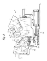
- Fig. 1 shows a negative-angle press-working die 1 according to an embodiment of the present invention, which forms an automobile panel or the like into a complicated cross-sectional shape.
- the negative-angle press-working die 1 includes an elevatable pad 3 fixed to an upper die 2, a laterally slidable aerial cam 4 serving as a slide cam, a rotary cam 5 which rotates about a rotational center 5c, a drive unit 6 for rotating the rotary cam 5, a slidable slide body 7 having a workpiece hold part 7a, and a slide drive unit 8 that slides the slide body 7.
- the aerial cam 4 serving as a slide cam is not limited to this aerial type, and may be slidably supported at a lower die.
- the aerial cam 4 is suspended from the upper die 2 via a cam surface 4b, and has a cam surface 4a on a bottom surface side, and a bending blade 4c formed at its distal end portion.
- the aerial cam 4 is supported at the upper die 2 so as to laterally slide along the cam surfaces 4a, 4b as the upper die 2 is elevated up and down.
- the rotary cam 5 is disposed to be rotatable about the rotational center 5c, has, on the top surface side, a bending part 5a for forming a negative angle portion in a workpiece to be subjected to bending and a cam surface 5b corresponding to the cam surface 4a of the aerial cam 4, and has, on one end side of the bottom surface, a slide plate 5d which abuts on the drive unit 6.
- the whole rotary cam 5 is rotated by the drive unit 6.
- the drive unit 6 is disposed under the rotary cam 5, and has a horizontally movable slide block 6b provided at a drive-axial distal end of an air cylinder 6a and having a tapered portion 6c on the distal end side of the upper surface.
- the rotary cam 5 is rotated as the tapered portion 6c abuts on the slide plate 5d of the rotary cam 5 to push up the slide plate 5d.
- the slide body 7 is disposed under the pad 3, has the hold part 7a provided at an upper portion on the bending part 5a side of the rotary cam 5 and constituting a part of a male die for workpiece forming, and is held to be slidable obliquely upward.
- an end face of the hold part 7a of the slide body 7 and an end face of the bending part 5a of the rotary cam 5 slidably abut on each other, and rotate together with the rotary cam 5 about the rotational center 5c.
- a projecting work surface (male die) for forming a workpiece 12 is formed.
- a recessed work surface (female die) corresponding to the former work surface is formed at the bottom side of the pad 3.
- the slide drive unit 8 includes a cam slide 9 having, on an upper side, a cam surface 9a on which the slide body 7 slides upward, and having a lower end supported at an end portion of the rotary cam 5 so as to be movable laterally, a coil spring 10 serving as an urging section to urge the cam slide 9 in a direction away from the rotational center of the rotary cam 5, and an upper die driver 11 having, at a lower end portion of a side face thereof, a cam surface 11 a which abuts on a cam surface 9b formed at an upper end portion of a side face of the cam slide 9 to forcibly move the cam slide 9 laterally, and fixed to the upper die 2.
- the aerial cam 4 and the upper die driver 11 are all at the top dead center, the workpiece 12 such as a body side outer panel, is placed in the die, and the drive unit 6 is driven first.
- the pad 3 supported by a spring 15 presses the workpiece 12 from above.
- the vertical side face 11 b of the upper die driver 11 comes in slide contact with the side end face 9c of the cam slide 9, thus keeping the cam slide 9 moved rightward.
- the cam surface 4a of the aerial cam 4 abuts on the cam surface 5b of the rotary cam 5, and moves on the cam surface 5b toward the bending part 5a located obliquely leftward as the upper die 2 further moves downward.
- the vertical side face 11 b of the upper die driver 11 and the side end face 9c of the cam slide 9 are formed and arranged so as to provide timings in the up and down direction.
- the bending blade 4c of the aerial cam 4 presses the workpiece 12 held between the bending blade 4c and the bending part 5a of the rotary cam 5 to effect deep bending (see Fig. 2 ).
- the upper die 2 further moves upward, so that the upper die driver 11 and the aerial cam 4 move upward.
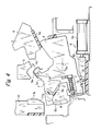
- the slide block 6b is moved rightward by the air cylinder 6a of the drive unit 6. Accordingly, the rotary cam 5 rotates about the rotational center 5c counterclockwise, causing the bending part 5a to move away from inside the workpiece 12.
- sufficient space for panel removal is secured under the workpiece 12, as shown in Fig. 4 . Therefore, such negative angle forming with deep bending is possible.
- the die 1 When the workpiece 12 after bending is removed from the die 1, the die 1 returns to the initial state shown in Fig. 1 .
- the slide body 7 which has the hold part 7a constituting a part of a male die for workpiece forming, and slides in the up and down direction is provided at the rotary cam 5, so that when the workpiece is subjected to bending, the hold part 7a is separated from the workpiece 12 first and the bending part 5a is rotated into the space formed by the separation of the hold part 7a so as to be separated from the workpiece 12.
- a negative-angle press-working die 1a includes a slide body 7 having a fixed punch 16 and a hold part 7a and being slidable obliquely upward and downward with respect to a workpiece 12a, a rotary cam 5 having a bending part 5a, and a slide cam 4d supported at a lower die and laterally slidable on the rotary cam 5, with a rotational center 5c set at a proper position.
- This structure can cause the rotary cam 5 to rotate counterclockwise to move the bending part 5a away from the bottom surface of the workpiece 12a, thus securing a panel removal clearance, as in the above-described embodiment.
Abstract
Description
- The present invention relates to a negative-angle press-working die, which performs bending or the like of an automobile panel with negative angle working.
- Negative angle working to be performed on a front pillar, roof and rear window of a body side outer panel of an automobile panel is difficult as the front pillar, roof and rear window have complicated cross-sectional shapes. Because the cross-sectional shape of a portion from the front pillar to the roof needs to keep the strength with a small cross section, negative angle forming of this part is particularly difficult. As a press-working die to overcome such difficulty, a press-working die disclosed in, for example,
JP-A-59-197318 Fig. 8A , the press-working die is of a columnar cam type that includes a lower die having ahold part 16b for holding a raw material on the upper portion of a fixedpunch 16a of the lower die, and a cam groove having an arc surface continual to thehold part 16b, a columnarrotary cam 17 which is provided at thelower die 14 to be rotatably inserted in the cam groove and has abending part 17a at its one end, an elevatable and laterally slidable aerial cam which is provided above therotary cam 17, has a bending blade at a distal end, and rotates therotary cam 17 in a direction of holding the raw material, and a pad elevatably disposed above thehold part 16b of the lower die. The press-working die performs complicated bending of the pillar (workpiece 12) with therotary cam 17. - Recently, the demanded cross-sectional shape of a workpiece is getting complicated, for example, from the one shown in
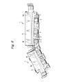
Fig. 8A to the one shown inFig. 8B , so that even the use of the conventional negative-angle press-working die makes it difficult to achieve negative angle forming. That is, as shown inFig. 8B , the shape is thin and has deep bending, so that the width where the fixedpunch 16a or hold part is present cannot be set, and with aclearance 18 for panel removal provided, the space becomes larger, so that the raw material panel cannot be pressed with the pad of the upper die. This leads to reduction in the quality of the formed panel. If the bending of the curved shape of a workpiece is deep and the level difference in the up and down direction is large, the separation line between the fixing punch and the rotary cam has different heights at individual cross sections, and designing the panel with a single cross section is not possible. It is therefore necessary to separate the press-working steps, or separate adie 20 of the columnar cam type into a front pillar A, roofs B, C, a rear D, and so forth, as shown inFig. 9 , which need to be arranged along the inclinations of the respective workpiece and need to be formed in multiple steps. - Accordingly, it is an object of the present invention to provide a negative-angle press-working die which overcomes the conventional problem and can form a negative angle with deep bending and can form a high-quality panel.
- To achieve the object, according to the invention, there is provided a negative-angle press-working die including an elevatable pad fixed to an upper die; a slide cam supported on the upper die or a lower die, forming a bending blade at one end portion, having cam surfaces on both upper and lower sides, and supported so as to laterally slide along the both cam surfaces; a rotary cam having, at one end thereof, a bending part which forms a negative-angle portion on a workpiece, having a cam surface abutting on one of the cam surfaces of the slide cam, and being rotatable about a rotational center; a slide body disposed under the pad, having a hold part provided at an upper portion on a bending part side of the rotary cam and constituting a part of a male die for workpiece forming, being elevatably held, and rotatable together with the rotary cam; a drive unit that rotates the rotary cam at a workpiece working position; and a slide drive unit that slides the slide body in an up and down direction.
- It is preferable that the drive unit should be disposed under the rotary cam, and have a horizontally movable slide block provided at a drive-axial distal end of an air cylinder and having a tapered portion at an upper surface on a distal end side, and the rotary cam should be rotated as the tapered portion abuts on a lower portion of the rotary cam to push up the lower portion.
- The slide drive unit preferably includes a cam slide having, on an upper side, a cam surface on which the slide body is slidable, and having a lower end supported at an end portion of the rotary cam so as to be movable laterally, an urging section that urges the cam slide in a direction away from the rotational center of the rotary cam, and an upper die driver having, at a lower end portion of a side face thereof, a cam surface which abuts on an upper end portion of a side face of the cam slide to forcibly move the cam slide laterally, and fixed to the upper die.
- The negative-angle press-working die according to the present invention not only can form a negative angle with deep bending, which cannot be achieved by a columnar cam type using the rotary cam of the prior art, but also need not form a panel removing clearance needed by the prior art to remove a panel, thereby improving the quality of the panel dramatically.
- Further, it becomes possible to keep separation of a die to a minimum, thereby enabling reduction of the working costs. Furthermore, it becomes possible to set the axis of the rotational center horizontal without inclination of the axis, thereby contributing reduction of production costs of the dies.
- The present invention particularly and preferably provides to enable forming a negative angle with deep bending and forming a high-quality panel, a negative-angle press-working die (1) including an elevatable pad (3) fixed to an upper die (2), a slide cam (4) supported slidable laterally on the upper die (2) or a lower die (14) and having a bending blade (4c), a rotary cam (5) rotatable about a rotational center (5c) having a bending part (5a) which forms a negative-angle portion on a workpiece (12) and a cam surface (5b) abutting on the slide cam (4), an elevatable slide body (7) disposed under the pad (3) rotatably together with the rotary cam (5) and having a hold part (7a) provided at an upper portion on a bending part side of the rotary cam (5) and constituting a part of a male die for workpiece forming, a drive unit (6) that rotates the rotary cam (5) to a workpiece working position, and a slide drive unit (8) that slides the slide body (7) in an up and down direction.
-
Fig. 1 is a longitudinal cross-sectional view showing the schematic structure of a negative-angle press-working die according to an embodiment of the present invention; -
Fig. 2 is a longitudinal cross-sectional view showing the movement of the negative-angle press-working die in bending a workpiece; -
Fig. 3 is a longitudinal cross-sectional view showing the return movement of the negative-angle press-working die after workpiece bending; -
Fig. 4 is a longitudinal cross-sectional view showing the initial state of the negative-angle press-working die after workpiece bending is completed; -
Fig. 5 is a longitudinal cross-sectional view showing the schematic structure of a negative-angle press-working die according to another embodiment of the present invention; -
Fig. 6 is a plan view showing an example of usage of the negative-angle press-working die according to the present invention; -
Fig. 7 is a front view showing a state where the axis of the rotational center of the negative-angle press-working die is set horizontal to a workpiece having a curved shape; -
Fig. 8A is a cross-sectional view of essential portions showing a conventional press-working die in use, andFig. 8B is a cross-sectional view of essential portions showing a state where a workpiece is bent deeper in the press-working die; and -
Fig. 9 is a front view showing an example of usage where a conventional press-working die is separated into four sections. -
Fig. 1 shows a negative-angle press-working die 1 according to an embodiment of the present invention, which forms an automobile panel or the like into a complicated cross-sectional shape. The negative-angle press-working die 1 includes anelevatable pad 3 fixed to anupper die 2, a laterally slidableaerial cam 4 serving as a slide cam, arotary cam 5 which rotates about arotational center 5c, adrive unit 6 for rotating therotary cam 5, aslidable slide body 7 having a workpiece holdpart 7a, and aslide drive unit 8 that slides theslide body 7. Theaerial cam 4 serving as a slide cam is not limited to this aerial type, and may be slidably supported at a lower die. - The
aerial cam 4 is suspended from theupper die 2 via acam surface 4b, and has acam surface 4a on a bottom surface side, and abending blade 4c formed at its distal end portion. Theaerial cam 4 is supported at theupper die 2 so as to laterally slide along thecam surfaces upper die 2 is elevated up and down. - The
rotary cam 5 is disposed to be rotatable about therotational center 5c, has, on the top surface side, abending part 5a for forming a negative angle portion in a workpiece to be subjected to bending and acam surface 5b corresponding to thecam surface 4a of theaerial cam 4, and has, on one end side of the bottom surface, aslide plate 5d which abuts on thedrive unit 6. The wholerotary cam 5 is rotated by thedrive unit 6. Thedrive unit 6 is disposed under therotary cam 5, and has a horizontallymovable slide block 6b provided at a drive-axial distal end of anair cylinder 6a and having atapered portion 6c on the distal end side of the upper surface. Therotary cam 5 is rotated as thetapered portion 6c abuts on theslide plate 5d of therotary cam 5 to push up theslide plate 5d. - The
slide body 7 is disposed under thepad 3, has thehold part 7a provided at an upper portion on thebending part 5a side of therotary cam 5 and constituting a part of a male die for workpiece forming, and is held to be slidable obliquely upward. As shown inFig. 1 , an end face of thehold part 7a of theslide body 7 and an end face of thebending part 5a of therotary cam 5 slidably abut on each other, and rotate together with therotary cam 5 about therotational center 5c. When the top surface of thehold part 7a slides obliquely upward and is aligned with the top surface of thebending part 5a, a projecting work surface (male die) for forming aworkpiece 12 is formed. A recessed work surface (female die) corresponding to the former work surface is formed at the bottom side of thepad 3. - The
slide drive unit 8 includes acam slide 9 having, on an upper side, acam surface 9a on which theslide body 7 slides upward, and having a lower end supported at an end portion of therotary cam 5 so as to be movable laterally, acoil spring 10 serving as an urging section to urge thecam slide 9 in a direction away from the rotational center of therotary cam 5, and anupper die driver 11 having, at a lower end portion of a side face thereof, acam surface 11 a which abuts on acam surface 9b formed at an upper end portion of a side face of thecam slide 9 to forcibly move thecam slide 9 laterally, and fixed to theupper die 2. - In the initial position state where the
upper die 2 of the negative-angle press-working die 1 with the foregoing structure is at the top dead center and thepad 3, theaerial cam 4 and theupper die driver 11 are all at the top dead center, theworkpiece 12 such as a body side outer panel, is placed in the die, and thedrive unit 6 is driven first. - As the
drive unit 6 is driven, a cylinder rod extends out and theslide block 6b at the distal end slides forward on aplate 13. Then, thetapered portion 6c of theslide block 6b abuts on theslide plate 5d and pushes up theslide plate 5d, so that therotary cam 5 rotates about therotational center 5c clockwise. When theslide block 6b further moves forward and theslide plate 5d comes to the horizontal upper surface of theslide block 6b, the rotation of therotary cam 5 stops. - The
slide body 7 andcam slide 9, supported on therotary cam 5, rotate together according to the rotation of therotary cam 5, so that aside end face 9c of thecam slide 9 becomes in parallel to avertical side face 11 b of theupper die driver 11. - Next, when the
upper die 2 moves down toward thelower die 14, first, thecam surface 11 a of theupper die driver 11 abuts on thecam surface 9b of thecam slide 9, moving thecam slide 9 rightward against the urging force of thecoil spring 10. The movement of thecam slide 9 causes the lower end face of theslide body 7 to slide on thecam surface 9a, pushing theslide body 7 obliquely upward, so that the top surface of thehold part 7a is level with the top surface of thebending part 5a, both of which abut on the bottom surface of theworkpiece 12. - Then, the
pad 3 supported by a spring 15 (seeFig. 1 ) or the like presses theworkpiece 12 from above. As theupper die 2 further moves downward, thevertical side face 11 b of theupper die driver 11 comes in slide contact with theside end face 9c of thecam slide 9, thus keeping thecam slide 9 moved rightward. Meanwhile, thecam surface 4a of theaerial cam 4 abuts on thecam surface 5b of therotary cam 5, and moves on thecam surface 5b toward thebending part 5a located obliquely leftward as theupper die 2 further moves downward. It is to be noted that thevertical side face 11 b of theupper die driver 11 and theside end face 9c of thecam slide 9 are formed and arranged so as to provide timings in the up and down direction. - The
bending blade 4c of theaerial cam 4 presses theworkpiece 12 held between thebending blade 4c and thebending part 5a of therotary cam 5 to effect deep bending (seeFig. 2 ). - Thereafter, when the
upper die 2 moves upward, as shown inFig. 3 , theaerial cam 4 and theupper die driver 11 move at the same time, so that thebending blade 4c moves away from thebending part 5a. When the position of contact between thecam slide 9 and theupper die driver 11 is shifted from between thevertical side face 11 b and theside end face 9c to between thecam surface 11a and thecam surface 9b, thecam slide 9 is urged by thecoil spring 10 to move leftward. This causes theslide body 7 to slide down on thecam surface 9a obliquely. Accordingly, thehold part 7a moves away from the bottom surface of theworkpiece 12. Thepad 3 is pulled upward via thespring 15 or the like. - Next, the
upper die 2 further moves upward, so that theupper die driver 11 and theaerial cam 4 move upward. Then theslide block 6b is moved rightward by theair cylinder 6a of thedrive unit 6. Accordingly, therotary cam 5 rotates about therotational center 5c counterclockwise, causing the bendingpart 5a to move away from inside theworkpiece 12. As a result, sufficient space for panel removal is secured under theworkpiece 12, as shown inFig. 4 . Therefore, such negative angle forming with deep bending is possible. - When the
workpiece 12 after bending is removed from the die 1, the die 1 returns to the initial state shown inFig. 1 . In the negative-angle press-working die 1 according to the present invention, as apparent from the above, theslide body 7 which has thehold part 7a constituting a part of a male die for workpiece forming, and slides in the up and down direction is provided at therotary cam 5, so that when the workpiece is subjected to bending, thehold part 7a is separated from theworkpiece 12 first and the bendingpart 5a is rotated into the space formed by the separation of thehold part 7a so as to be separated from theworkpiece 12. -
Fig. 5 shows another embodiment of the present invention. A negative-angle press-workingdie 1a includes aslide body 7 having a fixedpunch 16 and ahold part 7a and being slidable obliquely upward and downward with respect to aworkpiece 12a, arotary cam 5 having a bendingpart 5a, and aslide cam 4d supported at a lower die and laterally slidable on therotary cam 5, with arotational center 5c set at a proper position. This structure can cause therotary cam 5 to rotate counterclockwise to move the bendingpart 5a away from the bottom surface of theworkpiece 12a, thus securing a panel removal clearance, as in the above-described embodiment.
Claims (3)
- A negative-angle press-working die (1) comprising an elevatable pad (3) fixed to an upper die (2); a slide cam (4) supported on the upper die (2) or a lower die (14), forming a bending blade (4c) at one end portion, having cam surfaces (4a, 4b) on both upper and lower sides, and supported so as to laterally slide along the both cam surfaces (4a, 4b); and a rotary cam (5) having, at one end thereof, a bending part (5a) that forms a negative-angle portion on a workpiece (12), having a cam surface (5b) abutting on one of the cam surfaces of the slide cam, and being rotatable about a rotational center (5c); characterized by further comprising:a slide body (7) disposed under the pad (3), having a hold part (7a) provided at an upper portion on a bending part side of the rotary cam (5) and constituting a part of a male die for workpiece forming, elevatably held, and being rotatable together with the rotary cam;a drive unit (6) that rotates the rotary cam (5) at a workpiece working position; anda slide drive unit (8) that slides the slide body (7) in an up and down direction.
- The negative-angle press-working die according to claim 1, wherein the drive unit (6) is disposed under the rotary cam (5), and has a horizontally movable slide block (6b) provided at a drive-axial distal end of an air cylinder (6a) and having a tapered portion (6c) at an upper surface on a distal end side, and the rotary cam (5) is rotated as the tapered portion (6c) abuts on a lower portion (5d) of the rotary cam (5) to push up the lower portion.
- The negative-angle press-working die according to claim 1 or 2, wherein the slide drive (8) unit includes a cam slide (9) having, on an upper side, a cam surface (9a) on which the slide body (7) is slidable, and having a lower end supported at an end portion of the rotary cam (5) so as to be movable laterally, an urging section that urges the cam slide (9) in a direction away from the rotational center (5c) of the rotary cam (5), and an upper die driver (11) having, at a lower end portion of a side face thereof, a cam surface (11 a) which abuts on a cam surface (9b) formed at an upper end portion of a side face of the cam slide (9) to forcibly move the cam slide laterally, and fixed to the upper die (2).
Applications Claiming Priority (1)
| Application Number | Priority Date | Filing Date | Title |
|---|---|---|---|
| JP2007288585A JP5014069B2 (en) | 2007-11-06 | 2007-11-06 | Press mold |
Publications (2)
| Publication Number | Publication Date |
|---|---|
| EP2058061A1 true EP2058061A1 (en) | 2009-05-13 |
| EP2058061B1 EP2058061B1 (en) | 2010-05-19 |
Family
ID=40379826
Family Applications (1)
| Application Number | Title | Priority Date | Filing Date |
|---|---|---|---|
| EP08011615A Expired - Fee Related EP2058061B1 (en) | 2007-11-06 | 2008-06-26 | Negative-angle press-working die |
Country Status (6)
| Country | Link |
|---|---|
| US (1) | US7665341B2 (en) |
| EP (1) | EP2058061B1 (en) |
| JP (1) | JP5014069B2 (en) |
| KR (1) | KR20090046676A (en) |
| CN (1) | CN101428315A (en) |
| DE (1) | DE602008001300D1 (en) |
Cited By (9)
| Publication number | Priority date | Publication date | Assignee | Title |
|---|---|---|---|---|
| KR100971354B1 (en) | 2009-12-28 | 2010-07-20 | 주식회사 현대알비 | A plate edge banding machine |
| EP2431108A1 (en) * | 2010-09-17 | 2012-03-21 | Yourbusiness Co., Ltd. | Press die assembly |
| WO2012075363A1 (en) * | 2010-12-02 | 2012-06-07 | Norgren Automation Solutions, Inc. | Bending die with radial cam unit |
| EP2705913A1 (en) * | 2012-09-10 | 2014-03-12 | Peugeot Citroën Automobiles Sa | Die for a press for deep-drawing a metal sheet |
| DE102012210960A1 (en) | 2012-06-27 | 2014-04-03 | Bayerische Motoren Werke Aktiengesellschaft | Filling device for metal plate press processing mold, has eccentric mechanism provided with filling piece for filling kinematic locking device, and eccentric disk supported on eccentric disk accommodating part |
| FR3024380A1 (en) * | 2014-08-04 | 2016-02-05 | Peugeot Citroen Automobiles Sa | BINDING PRESS FOR BOTTOMING A PIECE OF SHEET IN COUNTER-TILE |
| FR3027828A1 (en) * | 2014-10-30 | 2016-05-06 | Peugeot Citroen Automobiles Sa | TOOLING FOR FORMING AN EDGE IN A COUNTER-TILT OF EMBROIDERY |
| FR3031322A1 (en) * | 2015-01-06 | 2016-07-08 | Peugeot Citroen Automobiles Sa | SHAPING A BOTTOM EDGE WITH COUNTER-TILE REFLEX |
| EP3100795A1 (en) | 2015-06-03 | 2016-12-07 | Peugeot Citroën Automobiles SA | Punch for forming by deep drawing an undercut edge of the deep drawn piece |
Families Citing this family (23)
| Publication number | Priority date | Publication date | Assignee | Title |
|---|---|---|---|---|
| US20080237961A1 (en) * | 2007-03-30 | 2008-10-02 | Honda Motor Co., Ltd. | Pad for holding blank and die assembly therewith |
| US8516874B2 (en) * | 2007-12-27 | 2013-08-27 | Toyota Motor Engineering & Manufacturing North America, Inc. | Pillar for motor vehicle and tool for making the same |
| JP5152047B2 (en) * | 2009-03-11 | 2013-02-27 | トヨタ自動車株式会社 | Press machine |
| DE102010018534A1 (en) * | 2010-04-27 | 2011-10-27 | Läpple Werkzeugbau GmbH | Device for molding a workpiece |
| US8371150B2 (en) * | 2010-11-09 | 2013-02-12 | Cheng Uei Precision Industry Co., Ltd. | Forming die |
| WO2013026138A1 (en) * | 2011-08-19 | 2013-02-28 | Magna International Inc. | Self-compensating retractable insert for high-temperature forming tools |
| KR101167042B1 (en) * | 2012-01-04 | 2012-07-31 | 주식회사 루보 | The device for forming negative angle |
| KR101455673B1 (en) * | 2012-11-06 | 2014-10-28 | 주식회사 성우하이텍 | Cam press apparatus |
| CN102962358A (en) * | 2012-11-22 | 2013-03-13 | 奇瑞汽车股份有限公司 | Rotary-type child and mother wedge mould |
| CN103357762B (en) * | 2013-07-18 | 2015-05-20 | 上海大众汽车有限公司 | Three-layer-superimposed direction-changing wedge mechanism, stamping die and stamping method |
| CN103433390B (en) * | 2013-07-25 | 2015-12-23 | 柳州职业技术学院 | A kind of rotary tapered wedge |
| KR101550619B1 (en) * | 2013-12-30 | 2015-09-07 | 현대자동차 주식회사 | Press device |
| CN104043718B (en) * | 2014-06-26 | 2016-04-20 | 梧州恒声电子科技有限公司 | A kind of oblique shock wave mould structure of frame series products of adjustable size |
| CN104190790B (en) * | 2014-08-13 | 2016-08-24 | 奇瑞汽车股份有限公司 | A kind of three action primary and secondary cam die and control methods thereof |
| CN104722659B (en) * | 2015-03-17 | 2017-03-08 | 安徽江淮汽车集团股份有限公司 | Tapered wedge rotating mechanism and diel |
| KR101655668B1 (en) | 2015-04-20 | 2016-09-07 | 기아자동차주식회사 | Cam type press die |
| JP6517622B2 (en) * | 2015-07-31 | 2019-05-22 | ダイハツ工業株式会社 | Roof side rail |
| KR101714256B1 (en) * | 2015-11-04 | 2017-03-08 | 현대자동차주식회사 | Swivel jig cam for machining burring hole of door inner panel and operation method thereof |
| CN108348975A (en) * | 2015-12-21 | 2018-07-31 | 标致雪铁龙汽车股份有限公司 | Operated pressing tool with the composite slider operated under same pressing stroke |
| US10486216B2 (en) | 2016-10-17 | 2019-11-26 | Ford Motor Company | Draw die and binder lock |
| JP7014131B2 (en) * | 2018-11-07 | 2022-02-01 | トヨタ車体株式会社 | Rotary cam type bending / bending composite mold |
| KR102173558B1 (en) * | 2020-03-11 | 2020-11-03 | 김종열 | Double cam press die for lower arm of car |
| CN114472717A (en) * | 2022-02-22 | 2022-05-13 | 四川成飞集成科技股份有限公司 | Pulley mechanism capable of moving automatically |
Citations (5)
| Publication number | Priority date | Publication date | Assignee | Title |
|---|---|---|---|---|
| JPS59197318A (en) | 1983-04-21 | 1984-11-08 | Daihatsu Motor Co Ltd | Die for press |
| JP2000271649A (en) * | 1999-03-24 | 2000-10-03 | Toyota Motor Corp | Press device |
| EP1044739A2 (en) * | 1999-04-15 | 2000-10-18 | Umix Co., Ltd. | Negative angular forming dies and pressing apparatus thereof |
| EP1698409A1 (en) * | 2005-03-02 | 2006-09-06 | Bayerische Motoren Werke Aktiengesellschaft | Device for a press for forming of a sheet-metal with a deformable section torwards an undercut-shape separated from the device |
| EP1847371A2 (en) * | 2006-04-17 | 2007-10-24 | Yourbusiness Co., Ltd. | Bearing Structure and Press Molding Apparatus Having the Structure |
Family Cites Families (5)
| Publication number | Priority date | Publication date | Assignee | Title |
|---|---|---|---|---|
| JP2001137946A (en) * | 1999-11-09 | 2001-05-22 | Toyota Motor Corp | Forming die |
| JP2004066314A (en) * | 2002-08-08 | 2004-03-04 | Your Business:Kk | Press-forming apparatus |
| JP4162579B2 (en) * | 2003-11-27 | 2008-10-08 | 株式会社ユアビジネス | Negative angle mold |
| JP2006116558A (en) * | 2004-10-20 | 2006-05-11 | Your Business:Kk | Press forming apparatus for metallic sheet |
| US7624615B2 (en) * | 2006-10-27 | 2009-12-01 | Chrysler Group Llc | Wedge activated rotating filler cam |
-
2007
- 2007-11-06 JP JP2007288585A patent/JP5014069B2/en not_active Expired - Fee Related
-
2008
- 2008-06-18 US US12/213,335 patent/US7665341B2/en not_active Expired - Fee Related
- 2008-06-26 DE DE602008001300T patent/DE602008001300D1/en active Active
- 2008-06-26 EP EP08011615A patent/EP2058061B1/en not_active Expired - Fee Related
- 2008-07-17 CN CNA2008101379679A patent/CN101428315A/en active Pending
- 2008-07-17 KR KR1020080069601A patent/KR20090046676A/en not_active Application Discontinuation
Patent Citations (5)
| Publication number | Priority date | Publication date | Assignee | Title |
|---|---|---|---|---|
| JPS59197318A (en) | 1983-04-21 | 1984-11-08 | Daihatsu Motor Co Ltd | Die for press |
| JP2000271649A (en) * | 1999-03-24 | 2000-10-03 | Toyota Motor Corp | Press device |
| EP1044739A2 (en) * | 1999-04-15 | 2000-10-18 | Umix Co., Ltd. | Negative angular forming dies and pressing apparatus thereof |
| EP1698409A1 (en) * | 2005-03-02 | 2006-09-06 | Bayerische Motoren Werke Aktiengesellschaft | Device for a press for forming of a sheet-metal with a deformable section torwards an undercut-shape separated from the device |
| EP1847371A2 (en) * | 2006-04-17 | 2007-10-24 | Yourbusiness Co., Ltd. | Bearing Structure and Press Molding Apparatus Having the Structure |
Cited By (21)
| Publication number | Priority date | Publication date | Assignee | Title |
|---|---|---|---|---|
| KR100971354B1 (en) | 2009-12-28 | 2010-07-20 | 주식회사 현대알비 | A plate edge banding machine |
| EP2431108A1 (en) * | 2010-09-17 | 2012-03-21 | Yourbusiness Co., Ltd. | Press die assembly |
| US9327330B2 (en) | 2010-12-02 | 2016-05-03 | Norgren Automation Solutions, Llc | Bending die with radial cam unit |
| WO2012075363A1 (en) * | 2010-12-02 | 2012-06-07 | Norgren Automation Solutions, Inc. | Bending die with radial cam unit |
| CN103260782A (en) * | 2010-12-02 | 2013-08-21 | 诺冠自动化解决方案有限责任公司 | Bending die with radial cam unit |
| US8789402B2 (en) | 2010-12-02 | 2014-07-29 | Norgren Automation Solutions, Llc | Bending die with radial cam unit |
| CN103260782B (en) * | 2010-12-02 | 2015-04-22 | 诺冠自动化解决方案有限责任公司 | Bending die with radial cam unit |
| US9032771B2 (en) | 2010-12-02 | 2015-05-19 | Norgren Automation Solutions, Llc | Bending die with radial cam unit |
| DE102012210960A1 (en) | 2012-06-27 | 2014-04-03 | Bayerische Motoren Werke Aktiengesellschaft | Filling device for metal plate press processing mold, has eccentric mechanism provided with filling piece for filling kinematic locking device, and eccentric disk supported on eccentric disk accommodating part |
| DE102012210960B4 (en) | 2012-06-27 | 2024-02-29 | Bayerische Motoren Werke Aktiengesellschaft | Filling slide arrangement for a press-connected sheet metal processing tool and press-connected sheet metal processing tool with such a filling slide arrangement |
| EP2705913A1 (en) * | 2012-09-10 | 2014-03-12 | Peugeot Citroën Automobiles Sa | Die for a press for deep-drawing a metal sheet |
| FR2995232A1 (en) * | 2012-09-10 | 2014-03-14 | Peugeot Citroen Automobiles Sa | PRESS TOOL FOR BINDING A SHEET |
| FR3024380A1 (en) * | 2014-08-04 | 2016-02-05 | Peugeot Citroen Automobiles Sa | BINDING PRESS FOR BOTTOMING A PIECE OF SHEET IN COUNTER-TILE |
| WO2016020594A1 (en) * | 2014-08-04 | 2016-02-11 | Peugeot Citroen Automobiles Sa | Stamping press for stamping a sheet metal part with an undercut cross-section |
| FR3027828A1 (en) * | 2014-10-30 | 2016-05-06 | Peugeot Citroen Automobiles Sa | TOOLING FOR FORMING AN EDGE IN A COUNTER-TILT OF EMBROIDERY |
| FR3031322A1 (en) * | 2015-01-06 | 2016-07-08 | Peugeot Citroen Automobiles Sa | SHAPING A BOTTOM EDGE WITH COUNTER-TILE REFLEX |
| WO2016110621A1 (en) * | 2015-01-06 | 2016-07-14 | Peugeot Citroen Automobiles Sa | Tool and a method for shaping an edge of a stamping piece having an undercut return |
| CN107107143A (en) * | 2015-01-06 | 2017-08-29 | 标致雪铁龙集团 | There is the shaping jig and method at the edge of the stamping parts of recess at undercutting |
| CN107107143B (en) * | 2015-01-06 | 2020-03-10 | 标致雪铁龙集团 | Forming tool and method for the edge of a stamping part with a recess at the undercut |
| EP3100795A1 (en) | 2015-06-03 | 2016-12-07 | Peugeot Citroën Automobiles SA | Punch for forming by deep drawing an undercut edge of the deep drawn piece |
| FR3036987A1 (en) * | 2015-06-03 | 2016-12-09 | Peugeot Citroen Automobiles Sa | SHAFT PUNCH BY EMBOSSING AN EDGE INTO A BOTTOM STRIP. |
Also Published As
| Publication number | Publication date |
|---|---|
| CN101428315A (en) | 2009-05-13 |
| JP2009113078A (en) | 2009-05-28 |
| JP5014069B2 (en) | 2012-08-29 |
| EP2058061B1 (en) | 2010-05-19 |
| KR20090046676A (en) | 2009-05-11 |
| US7665341B2 (en) | 2010-02-23 |
| DE602008001300D1 (en) | 2010-07-01 |
| US20090113978A1 (en) | 2009-05-07 |
Similar Documents
| Publication | Publication Date | Title |
|---|---|---|
| EP2058061B1 (en) | Negative-angle press-working die | |
| US5784916A (en) | Thin sheet forming die assembly including a lower die having plural parallel rotating cylindrical members | |
| US5746082A (en) | Thin sheet forming die assembly including lower die cylindrical member having varied diameters | |
| CN205519196U (en) | Deburring that becomes negative angle degree with pressing direction slide wedge that punches a hole | |
| CN210632751U (en) | Bending device for workpiece machining | |
| EP3294498B1 (en) | Method and machining device for clamping and machining an electrical enclosure component | |
| US8474296B2 (en) | Formation tool for a punching machine | |
| CN106825231B (en) | Tool for a stamping machine for reshaping a part of a plate-shaped workpiece and method for using same | |
| CN108043953B (en) | Wiper arm flat iron integrated into one piece processing equipment is scraped to wiper | |
| US6923103B2 (en) | Machine for the continuous multi-stroke slotting of plate-shaped workpieces | |
| JP5371177B2 (en) | Bending die in punch press and processing method using the bending die | |
| EP2379318B1 (en) | A punch | |
| JP2005246410A (en) | Press die | |
| EP3147044B1 (en) | Method and apparatus for forging heterogeneous material | |
| JP2008229670A (en) | Hemming device and hemming method | |
| CN109648339A (en) | A kind of plate forming cutting integration apparatus | |
| EP2822713B1 (en) | Tool for press-forming and flanging the edges of a vehicle bonnet | |
| JP2004042109A (en) | Apparatus for moving rotary cam in negative angle shaping die | |
| CN101773966B (en) | Gear type bending die | |
| JP6619595B2 (en) | Press machine | |
| JP2007210029A (en) | Apparatus and method for bending side of body panel for vehicle and body panel for vehicle | |
| FR3100726A1 (en) | Device for punching a sheet in concurrent directions, by bearing against one another by sliders carrying respective punches. | |
| CN212443573U (en) | Local thinning die for workpiece | |
| CN110586770B (en) | Progressive radius stamping die | |
| WO2016149681A1 (en) | Method and machine for bending metal |
Legal Events
| Date | Code | Title | Description |
|---|---|---|---|
| PUAI | Public reference made under article 153(3) epc to a published international application that has entered the european phase |
Free format text: ORIGINAL CODE: 0009012 |
|
| AK | Designated contracting states |
Kind code of ref document: A1 Designated state(s): AT BE BG CH CY CZ DE DK EE ES FI FR GB GR HR HU IE IS IT LI LT LU LV MC MT NL NO PL PT RO SE SI SK TR |
|
| AX | Request for extension of the european patent |
Extension state: AL BA MK RS |
|
| 17P | Request for examination filed |
Effective date: 20090610 |
|
| GRAP | Despatch of communication of intention to grant a patent |
Free format text: ORIGINAL CODE: EPIDOSNIGR1 |
|
| AKX | Designation fees paid |
Designated state(s): DE FR IT |
|
| GRAS | Grant fee paid |
Free format text: ORIGINAL CODE: EPIDOSNIGR3 |
|
| GRAA | (expected) grant |
Free format text: ORIGINAL CODE: 0009210 |
|
| AK | Designated contracting states |
Kind code of ref document: B1 Designated state(s): DE FR IT |
|
| REF | Corresponds to: |
Ref document number: 602008001300 Country of ref document: DE Date of ref document: 20100701 Kind code of ref document: P |
|
| PGFP | Annual fee paid to national office [announced via postgrant information from national office to epo] |
Ref country code: FR Payment date: 20100630 Year of fee payment: 3 |
|
| PGFP | Annual fee paid to national office [announced via postgrant information from national office to epo] |
Ref country code: DE Payment date: 20100729 Year of fee payment: 3 |
|
| PLBE | No opposition filed within time limit |
Free format text: ORIGINAL CODE: 0009261 |
|
| STAA | Information on the status of an ep patent application or granted ep patent |
Free format text: STATUS: NO OPPOSITION FILED WITHIN TIME LIMIT |
|
| PG25 | Lapsed in a contracting state [announced via postgrant information from national office to epo] |
Ref country code: IT Free format text: LAPSE BECAUSE OF FAILURE TO SUBMIT A TRANSLATION OF THE DESCRIPTION OR TO PAY THE FEE WITHIN THE PRESCRIBED TIME-LIMIT Effective date: 20100519 |
|
| 26N | No opposition filed |
Effective date: 20110222 |
|
| REG | Reference to a national code |
Ref country code: DE Ref legal event code: R097 Ref document number: 602008001300 Country of ref document: DE Effective date: 20110221 |
|
| REG | Reference to a national code |
Ref country code: FR Ref legal event code: ST Effective date: 20120229 |
|
| REG | Reference to a national code |
Ref country code: DE Ref legal event code: R119 Ref document number: 602008001300 Country of ref document: DE Effective date: 20120103 |
|
| PG25 | Lapsed in a contracting state [announced via postgrant information from national office to epo] |
Ref country code: FR Free format text: LAPSE BECAUSE OF NON-PAYMENT OF DUE FEES Effective date: 20110630 Ref country code: DE Free format text: LAPSE BECAUSE OF NON-PAYMENT OF DUE FEES Effective date: 20120103 |