EP1847371A2 - Bearing Structure and Press Molding Apparatus Having the Structure - Google Patents
Bearing Structure and Press Molding Apparatus Having the Structure Download PDFInfo
- Publication number
- EP1847371A2 EP1847371A2 EP06121260A EP06121260A EP1847371A2 EP 1847371 A2 EP1847371 A2 EP 1847371A2 EP 06121260 A EP06121260 A EP 06121260A EP 06121260 A EP06121260 A EP 06121260A EP 1847371 A2 EP1847371 A2 EP 1847371A2
- Authority
- EP
- European Patent Office
- Prior art keywords
- support shaft
- bearing
- rotational die
- bearing hole
- pressing
- Prior art date
- Legal status (The legal status is an assumption and is not a legal conclusion. Google has not performed a legal analysis and makes no representation as to the accuracy of the status listed.)
- Withdrawn
Links
- 238000000465 moulding Methods 0.000 title claims abstract description 28
- 238000003825 pressing Methods 0.000 description 55
- 238000000034 method Methods 0.000 description 4
- 230000005484 gravity Effects 0.000 description 2
- 238000004519 manufacturing process Methods 0.000 description 2
- 230000015572 biosynthetic process Effects 0.000 description 1
- 230000003247 decreasing effect Effects 0.000 description 1
- 238000006073 displacement reaction Methods 0.000 description 1
- 238000003780 insertion Methods 0.000 description 1
- 230000037431 insertion Effects 0.000 description 1
- 230000002265 prevention Effects 0.000 description 1
- 238000000926 separation method Methods 0.000 description 1
Images


Classifications
-
- F—MECHANICAL ENGINEERING; LIGHTING; HEATING; WEAPONS; BLASTING
- F16—ENGINEERING ELEMENTS AND UNITS; GENERAL MEASURES FOR PRODUCING AND MAINTAINING EFFECTIVE FUNCTIONING OF MACHINES OR INSTALLATIONS; THERMAL INSULATION IN GENERAL
- F16C—SHAFTS; FLEXIBLE SHAFTS; ELEMENTS OR CRANKSHAFT MECHANISMS; ROTARY BODIES OTHER THAN GEARING ELEMENTS; BEARINGS
- F16C35/00—Rigid support of bearing units; Housings, e.g. caps, covers
- F16C35/02—Rigid support of bearing units; Housings, e.g. caps, covers in the case of sliding-contact bearings
-
- B—PERFORMING OPERATIONS; TRANSPORTING
- B21—MECHANICAL METAL-WORKING WITHOUT ESSENTIALLY REMOVING MATERIAL; PUNCHING METAL
- B21D—WORKING OR PROCESSING OF SHEET METAL OR METAL TUBES, RODS OR PROFILES WITHOUT ESSENTIALLY REMOVING MATERIAL; PUNCHING METAL
- B21D7/00—Bending rods, profiles, or tubes
- B21D7/02—Bending rods, profiles, or tubes over a stationary forming member; by use of a swinging forming member or abutment
- B21D7/024—Bending rods, profiles, or tubes over a stationary forming member; by use of a swinging forming member or abutment by a swinging forming member
- B21D7/028—Bending rods, profiles, or tubes over a stationary forming member; by use of a swinging forming member or abutment by a swinging forming member and altering the profile at the same time, e.g. forming bumpers
-
- B—PERFORMING OPERATIONS; TRANSPORTING
- B21—MECHANICAL METAL-WORKING WITHOUT ESSENTIALLY REMOVING MATERIAL; PUNCHING METAL
- B21D—WORKING OR PROCESSING OF SHEET METAL OR METAL TUBES, RODS OR PROFILES WITHOUT ESSENTIALLY REMOVING MATERIAL; PUNCHING METAL
- B21D19/00—Flanging or other edge treatment, e.g. of tubes
- B21D19/08—Flanging or other edge treatment, e.g. of tubes by single or successive action of pressing tools, e.g. vice jaws
- B21D19/082—Flanging or other edge treatment, e.g. of tubes by single or successive action of pressing tools, e.g. vice jaws for making negative angles
- B21D19/086—Flanging or other edge treatment, e.g. of tubes by single or successive action of pressing tools, e.g. vice jaws for making negative angles with rotary cams
-
- F—MECHANICAL ENGINEERING; LIGHTING; HEATING; WEAPONS; BLASTING
- F16—ENGINEERING ELEMENTS AND UNITS; GENERAL MEASURES FOR PRODUCING AND MAINTAINING EFFECTIVE FUNCTIONING OF MACHINES OR INSTALLATIONS; THERMAL INSULATION IN GENERAL
- F16B—DEVICES FOR FASTENING OR SECURING CONSTRUCTIONAL ELEMENTS OR MACHINE PARTS TOGETHER, e.g. NAILS, BOLTS, CIRCLIPS, CLAMPS, CLIPS OR WEDGES; JOINTS OR JOINTING
- F16B35/00—Screw-bolts; Stay-bolts; Screw-threaded studs; Screws; Set screws
-
- F—MECHANICAL ENGINEERING; LIGHTING; HEATING; WEAPONS; BLASTING
- F16—ENGINEERING ELEMENTS AND UNITS; GENERAL MEASURES FOR PRODUCING AND MAINTAINING EFFECTIVE FUNCTIONING OF MACHINES OR INSTALLATIONS; THERMAL INSULATION IN GENERAL
- F16C—SHAFTS; FLEXIBLE SHAFTS; ELEMENTS OR CRANKSHAFT MECHANISMS; ROTARY BODIES OTHER THAN GEARING ELEMENTS; BEARINGS
- F16C17/00—Sliding-contact bearings for exclusively rotary movement
- F16C17/02—Sliding-contact bearings for exclusively rotary movement for radial load only
- F16C17/022—Sliding-contact bearings for exclusively rotary movement for radial load only with a pair of essentially semicircular bearing sleeves
Definitions
- the present prevention relates to an apparatus of molding a member used for a front fender or the like of an automobile by pressing, and particularly relates to a structure of a bearing for pivoting a support shaft of a rotational die (swing die) used for a negative-angle molding mechanism or the like in pressing, and press molding apparatus having the bearing structure.
- a rotation body bearing is known, the bearing is divided into a fitting base member and a covering member so that dividing the bearing hole in semicircular, and the fitting base member is fastened on an press apparatus body, a support shaft of the rotation body is placed on the base member to be held with the covering member, and a fastening bolt hole is made in a direction perpendicular to the hole (refer to JP-A-2005-249019 ).
- This type of technique in the related art is generally configured in a way that support shafts are provided in the left and right of a rotational die for supporting the rotational die during rotation, and the support shafts are rotatably pivoted by bearing holes formed in the bearing.
- the rotational die used for pressing is formed with high dimension accuracy of about 1/100 mm in tolerance between the support shaft and the bearing hole, and the rotational die is made in a zero contact condition with a predetermined position in a lower mold in which the rotational die is provided in order to prevent displacement of the die during pressing, or excessive application of pressure (load) to the support shafts at a pressing position.
- the troubles include:
- the technique in the related art has the following difficulty: since tolerance between the support shaft and the bearing hole is made in the high dimension accuracy of about 1/100 mm, and work surfaces are contacted with such accuracy, it is obvious that manufacturing accuracy of the support shaft and the bearing hole is hard to be kept, in addition, operation of assembling the support shaft and the bearing hole (operation of setting the rotational die in the predetermined position in the lower mold) formed with such high accuracy becomes more difficult, consequently much time is required for the assembling operation of them, and the troubles such as insufficient rotation of the rotational die and breakage of the support shaft may occur after assembling.
- the bearing structure according to the embodiment of the invention is a structure of bearing for rotatably pivoting a support shaft of a rotational die arranged in press molding apparatus by a bearing hole, which is configured in a way that inner diameter in at least an upper side of the bearing hole with respect to a horizontal line is formed slightly large compared with diameter of the support shaft, and a space is provided between the inner diameter in the upper side of the bearing hole and the support shaft.
- Press molding apparatus is configured in a way that it has a lower mold having at least a rotational die and an upper mold facing the lower mold, and a support shaft provided in the rotational die is rotatably pivoted by a bearing hole of a bearing provided in the lower mold, wherein inner diameter in at least an upper side of the bearing hole with respect to a horizontal line is formed slightly large compared with diameter of the support shaft, and a space is provided between the inner diameter in the upper side of the bearing hole and the support shaft.
- an end of the rotational die in a vertical or horizontal direction from the support shaft is preferably situated slightly near a release direction side with respect to the vertical or horizontal direction from the support shaft.
- the bearing structure according to the invention is the structure of the bearing for rotatably pivoting the support shaft of the rotational die arranged in the press molding apparatus by the bearing hole, which is configured in a way that the inner diameter in at least the upper side of the inner diameter of the bearing hole with respect to the horizontal line is formed slightly large compared with diameter of the support shaft, and the space is provided between the inner diameter in the upper side of the bearing hole and the support shaft, and the press molding apparatus is configured in a way that it has the lower mold having at least the rotational die therein and the upper mold facing the lower die, and the support shaft provided in the rotational die is rotatably pivoted by the bearing hole of the bearing provided in the lower mold, wherein the inner diameter in at least the upper side of the bearing hole with respect to the horizontal line is formed slightly large compared with the diameter of the support shaft, and the space is provided between the inner diameter in the upper side of the bearing hole and the support shaft; thereby excellent advantages are exhibited, that is, the rotational die and a predetermined position in the lower mold where
- the end of the rotational die in the vertical or horizontal direction from the support shaft is situated slightly near the release direction side with respect to the vertical or horizontal direction from the support shaft, thereby an excellent advantage is exhibited, that is, occurrence of the troubles such as insufficient rotation of the rotational die and breakage of the support shaft is further reduced.
- Figs. 1 to 3 schematically show an internal structure of press molding apparatus 1 in a cross section view.
- Fig. 1 shows a condition before performing pressing using a rotational die 3 to a sheet material 2 as a workpiece;
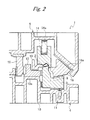
- Fig. 2 shows a condition immediately after pressing the sheet material 2 by the rotational die 3;
- Fig. 3 shows a condition where the rotational die 3 is separated from the sheet material 2 after pressing. While the rotational die 3 is in an L-shape here, it may be in any other shape such as a cylindrical shape.
- the rotational die 3 is arranged in a rotatable manner with a support shaft 6 as a center.
- Fig. 4 schematically shows a bearing 7 provided in the rotational die 3 in a schematic view, the bearing being for rotatably pivoting the support shaft 6; and Fig. 5 shows a vertical section of the bearing.
- the bearing 7 is provided in a predetermined position in the lower mold 4.
- a bearing hole 8 for rotatably pivoting the support shaft 6 is formed in the bearing 7, a bearing hole 8 for rotatably pivoting the support shaft 6 is formed.
- a bearing 8a may be arranged in the bearing hole 8 so that the support shaft 6 can be rotated more easily.
- the bearing 7 is preferably provided in a manner of being separated into a bearing body 7a situated at a lower side of the support shaft 6 for substantially pivoting the support shaft 6 when the support shaft 6 is inserted, and a bearing cover member 7b being situated at an upper side of the support shaft 6 to cover the upper side of the support shaft 6 and thus preventing falling off of the shaft and supplementarily pivoting the support shaft 6.
- inner diameter of the bearing hole 8 (or bearing 8a) and diameter of the support shaft 6 are preferably formed with high dimension accuracy within 1/100 mm to keep accuracy in pressing.
- inner diameter of the bearing body 7a and the diameter of the support shaft 6 are preferably made with high dimension accuracy within 1/100 mm
- inner diameter of the bearing cover member 7b and the diameter of the support shaft 6 may be in a freely fitting condition in some degree if the member 7b can supplementarily pivot the upper side of the support shaft 6, because the bearing cover member 7b does not substantially pivot the support shaft 6 due to gravity.
- the bearing body 7a and the bearing cover member 7b are assembled by fastening them using bolts 9 or the like after the support shaft 6 has been inserted.
- the bearing body 7a and the bearing cover member 7b are preferably separated at a horizontal line 8c passing through a center of the inner diameter of the bearing hole 8 formed at a side of the bearing body 7a, as shown in Fig. 6A showing the periphery of the bearing hole 8 in an enlarged manner.
- the horizontal line 8c passing through the center of the inner diameter of the bearing hole 8 formed at the side of the bearing body 7a means an imaginary line passing through a substantially central portion 8d of the bearing hole 8 (position corresponding to a central portion of the support shaft 6 when the support shaft 6 is inserted), and being in a perpendicular direction (horizontal direction) to a gravity direction (vertical direction) applied to the support shaft 6 to be inserted.
- the inner diameter of the bearing body 7a separated by the horizontal line 8c passing through the center of the inner diameter of the bearing hole 8 formed at the side of the bearing body 7a, that is, inner diameter of a lower-side bearing hole 8e in a lower side of the bearing 7 is formed in a semicircular shape to have a diameter with high dimension accuracy within 0 mm to +1/100 mm compared with the diameter of the support shaft 6.
- the inner diameter of the bearing cover member 7b that is, inner diameter of an upper-side bearing hole 8f in an upper side of the bearing 7 is formed in a semicircular shape having a diameter slightly large compared with the diameter of the support shaft 6, and preferably having a diameter approximately 0.2 mm larger than the diameter of the support shaft 6 irrespective of size of the support shaft 6.
- the upper-side bearing hole 8f formed in the bearing cover member 7b can supplementarily pivot the support shaft 6 by covering the upper side of the support shaft 6 in a slight freely-fitting-condition in a degree that the support shaft 6 does not fall off, and work accuracy is not inhibited during pressing.
- the upper-side bearing hole 8f has an extremely large diameter compared with the diameter of the support shaft 6, work accuracy of the hole is inhibited during pressing.
- the hole is formed to have a diameter approximately 0.2 mm large compared with the diameter of the support shaft 6, work accuracy of the hole is not inhibited during pressing.
- An inner shape of the hole is not limited to the semicircular shape, and for example, may be an elliptic shape.
- the inner diameter in the upper side of the bearing hole 8 with respect to the horizontal line that is, the inner diameter of the upper-side bearing hole 8f is formed slightly large compared with the diameter of the support shaft 6 in this way, thereby a space can be provided between the inner diameter in the upper side of the bearing hole 8 and the support shaft 6. Therefore operation of setting the rotational die 3 in the predetermined position in the lower mold 4, that is, operation of inserting the support shaft 6 into the bearing hole 8 of the bearing 7 for assembling can be easily performed.
- the bearing 7 may be singly provided in part of the lower mold 4, or may be formed in a cavity 10 of the lower mold 4.
- the bearing hole 8 need not be necessarily separated into the upper side and the lower side with respect to the horizontal line 8c of the inner diameter, and the upper side and the lower side may be integrally formed if a shape of the inner diameter is made in a manner that the upper side is formed to have a diameter slightly large compared with the diameter of the support shaft 6, and the lower side is formed to have approximately the same diameter as the diameter of the support shaft 6 with the horizontal line 8C as a border.
- a lift pin 11 is arranged in the cavity 10 at a lower side (bottom side) of the rotational die 3 in the lower mold 4, as shown in Figs. 1 to 3, which can project or submerge by vertically sliding.
- the lift pin 1 projects from the cavity 10 by vertically sliding, it can rotate the rotational die 3 by pressing the bottom of the rotational die 3.
- a pressing cum 12 which is slidable in a left and right direction in the figure, is arranged at a backside of the rotational die 3 in the lower mold 4.
- the pressing cum 12 is slidable in a space between an upper side 10a of the cavity 10 at the backside of the rotational die 3 and a sheet material receiver 13 on which the sheet material 2 is set during pressing.
- the sheet material receiver 13 is formed in accordance with a processed shape of the sheet material 2 such that it follows the shape.
- the upper mold 5 facing the lower mold 4 is provided above the lower mold 4, and the whole body of the mold 5 is moved in a vertical direction. That is, when the sheet material 2 as a workpiece is set on the sheet material receiver 13 of the lower mold 4 (refer to Fig. 1), the upper mold 5 is kept above, and after the sheet material 2 has been set on the sheet material receiver 13, the upper mold 5 is lowered for pressing (refer to Fig. 2).
- An upper pad 14 for pressing an upper part of the sheet material 2 set on the sheet material receiver 13 is arranged in the upper mold 5, the pad being formed in accordance with the shape of the sheet material 2.
- the upper part of the sheet material 2 set on the sheet material receiver 13 is pressed by the upper pad 14, thereby the sheet material 2 can be fixed such that the sheet material 2 is not displaced during pressing the sheet material 2.
- a cushion spring 14a is provided between the upper pad 14 and the upper mold 5, and the upper part of the sheet material 2 can be fixed by being pressed at appropriate pressing force by the cushion spring 14a.
- a doweling 15 is further arranged in the upper mold 5 in a downward projecting manner such that when the upper mold 5 is lowered, the doweling is lowered in a backside of the pressing cum 12 arranged in the lower mold 4, that is, in a left side of the pressing cum 12 in the figure.
- the doweling 15 is not contacted to the backside of the pressing cum 12, however, when the upper mold 5 is lowered, it is contacted to the backside of the pressing cum 12, and presses the backside of the pressing cum 12, thereby slides the pressing cum 12 to a position near the rotational die 3 and keeps the cum at the position.
- the pressing cum 12 is pushed to the backside of the rotational die 3 by the die 3 rotated by the lift pin 11 projecting upward, thereby slides in a left direction in the figure, and when the upper mold 5 is lowered, as shown in Fig. 2, the pressing cum 12 is pressed by the doweling 15 and thus slides in a right direction in the figure, and kept at a certain position in a condition that the rotational die 3 is pushed and thereby rotated at a predetermined angle.
- a slide cum 16 for molding is arranged in the right of the upper pad 14 of the upper mold 5, which is for pressing a working portion of the sheet material 2 fixed on the sheet material receiver 13 by the upper pad 14, and pressing the sheet material 2 into an intended shape between the slide cum 16 and the rotational die 3.
- the slide cum 16 is arranged in a slidable manner on a sliding area 16a provided in the upper mold 5.
- the sliding area 16a is provided in an oblique manner, and when the upper mold 5 is lowering and thus a lower part of the slide cum 16 is contacted to a sliding surface 3a of the rotational die 3, then the upper mold 5 is further lowering, the slide cum slides obliquely upward (in an upper left direction in the figure) along the sliding area 16a. That is, since height of the sliding surface 3a of the rotational die 3 is fixed, the slide cum 16 slides in a substantially left direction in the figure to press the working portion of the sheet material 2, so that pressing can be carried out.
- steps that the press molding apparatus 1 is operated to perform pressing of the sheet material 2 are sequentially described.
- Such operation of setting the sheet material 2 on the sheet material receiver 13 may be performed by using a predetermined device such as conveyer, or may be manually performed.
- the slide cum 16 arranged in the upper mold 5 slides obliquely downward (in a lower right direction in the figure) to a predetermined position along the sliding area 16a due to its own weight.
- the lift pin 11 provided in the lower mold 4 slides upward and projects from the cavity 10, and presses a bottom near a front of the rotational die 3, thereby the rotational die 3 is rotated counterclockwise in the figure.
- the rotational die 3 is rotated, thereby a molding part 3b of the rotational die 3 is separated from the sheet material 2 set on the sheet material receiver 13, or rotated in the left direction in the figure, that is, rotated to a side in a release direction as a backside direction of the rotational die 3.
- the sheet material 2 can be easily set.
- the lift pin 11 slides downward along with lowering of the upper mold 5 to be submerged into the cavity 10.
- the rotational die 3 is rotated clockwise in the figure along with submergence of the lift pin 11, that is, rotated to a fixing direction side with the support shaft 6 as a center due to its own weight, then the bottom of the rotational die 3 is contacted to the cavity 10, thereby rotation of the rotational die 3 is stopped, and such a condition is kept.
- the inner diameter in the upper side of the bearing hole 8 with respect to the horizontal line 8c passing through the center of the inner diameter, the upper side being formed in the bearing body 7a side, is formed slightly large compared with the diameter of the support shaft 6, and thus a space is provided between the inner diameter in the upper side of the bearing hole 8 and the support shaft 6, therefore even if the bottom contact end 3c of the rotational die 3 is contacted to the cavity 10 before the whole bottom of the rotational die 3 is contacted to the cavity 10, the support shaft 6 is in a slightly floating condition in the bearing hole 8 as shown in Fig. 6B, and therefore rotation of the rotational die 3 is not inhibited, consequently occurrence of the troubles such as insufficient rotation of the rotational die 3 and breakage of the support shaft 6 can be reduced.
- the inner diameter in the upper side of the bearing hole 8 with respect to the horizontal line 8c passing through the center of the inner diameter, the upper side being formed in the bearing body 7a side, is formed slightly large compared with the diameter of the support shaft 6, and thus a space is provided between the inner diameter in the upper side of the bearing hole 8 and the support shaft 6, thereby the axis of the support shaft 6 is movable to a slightly high position compared with a central position of the bearing hole 8, and thereby the rotational die 3 and the predetermined position in the lower mold 4 where the rotational die 3 is to be provided can be securely set in a zero contact manner, and occurrence of the troubles such as insufficient rotation of the rotational die 3 and breakage of the support shaft 6 can be reduced.
- a space between the inner diameter of the bearing hole 8 in a condition that the support shaft 6 is slightly floating in the bearing hole 8 and the support shaft 6 at the lower side of the bearing hole 8, that is, a space between the lower-side bearing hole 8e and the support shaft 6 may be about 0 mm to 0.05 mm, and the space at the upper side of the bearing hole 8 in the condition, that is, a space between the upper-side bearing hole 8f and the support shaft 6 can be about 0.15 mm to 0.2 mm.
- the bottom end 3c is formed to be situated at a slightly release direction side with respect to a position at which the bottom of the rotational die 3 intersects orthogonally with a perpendicular from the center of the support shaft 6 to the bottom, that is, situated at a counterclockwise side in the figure.
- the bottom end 3c is formed in this way, thereby when the rotational die 3 is rotated in the release direction, compared with a case of forming the end 3c at the position at which the bottom of the rotational die 3 intersects orthogonally with the perpendicular to the bottom, a space is produced between the bottom contact end 3c of the rotational die 3 and the lower mold 4 and thus contact resistance between them is reduced, consequently occurrence of the troubles such as insufficient rotation of the rotational die 3 and breakage of the support shaft 6 is further reduced.
- bottom contact end 3c is situated at a position of a line (imaginary line a') as a result of counterclockwise rotation of a line (imaginary line a) from the center of the support shaft 6 to an extension of the bottom of the rotational die 3 by a predetermined angle ⁇ , consequently rotation radius with the support shaft 6 as a center can be decreased by c as shown in Fig. 8.
- the doweling 15 provided in the upper mold 5 is lowered along with lowering of the upper mold 5, the doweling 15 is contacted to the backside of the pressing cum 12 and presses the cum, thereby as shown in Fig. 2, the pressing cum 12 is slid to a position near the rotational die 3, or in the right direction in the figure, and fixed and kept at the position. That is, since a position of the pressing cum 12 is kept while the pressing cum 12 is contacted to the backside of the rotational die 3, the rotational die 3 is fixed to the position without moving or rotating in a backside direction.
- the upper pad 14 provided in the upper mold 5 presses an upper part of the sheet material 2 set on the sheet material receiver 13, and fixes it not to be displaced.
- the slide cum 16 arranged in the sliding area 16a slides in the left direction in the figure and thus presses the working portion of the sheet material 2, so that pressing is carried out.
- the rotational die 3 whose posture is fixed by the pressing cum 12 is used, and pressing is carried out to the sheet material 2 securely fixed by the sheet material receiver 13 and the upper pad 14, accuracy of products manufactured by the pressing is improved.
- Patches 17 are provided to a contact surface between the rotational die 3 and the cavity 10, contact surface between the rotational die 3 and the pressing cum 12, contact surface between the rotational die 3 and the slide cum 16, contact surface between the pressing cum 12 and the sheet material receiver 13, and contact surface between the pressing cum 12 and the doweling 15, respectively, so that contact resistance between them is reduced.
- the whole inner diameter of the bearing hole 8 may be formed slightly large compared with the diameter of the support shaft 6.
- the rotational die 3 and the predetermined position in the lower mold 4 in which the rotational die 3 is provided are set in the zero contact manner.
- the structure of the bearing according to the invention and the press molding apparatus having the structure facilitate operation of inserting the support shaft into the bearing hole formed in the bearing and setting the rotational die in the predetermined position in the lower mold, and allow reduction in occurrence of troubles such as insufficient rotation of the rotational die and breakage of the support shaft, consequently contribute to improvement in manufacturing efficiency and quality of pressing products.
Landscapes
- Engineering & Computer Science (AREA)
- Mechanical Engineering (AREA)
- General Engineering & Computer Science (AREA)
- Mounting, Exchange, And Manufacturing Of Dies (AREA)
- Bending Of Plates, Rods, And Pipes (AREA)
- Sliding-Contact Bearings (AREA)
- Moulds For Moulding Plastics Or The Like (AREA)
- Shaping Metal By Deep-Drawing, Or The Like (AREA)
Abstract
While a rotational die and a predetermined position of a lower mold in which the rotational die is provided can be set in a zero contact manner, operation of setting the rotational die in the predetermined position of the lower mold can be easily performed, and occurrence of troubles such as insufficient rotation of the rotational die and breakage of support shafts is reduced. To realize this, in a structure of bearing (7) for rotatably pivoting a support shaft (6) of a rotational die (3) arranged in press molding apparatus (1) by a bearing hole (8), inner diameter in at least an upper side of the bearing hole with respect to a horizontal line passing through a center of the bearing hole is formed slightly large compared with diameter of the support shaft, and a space is provided between the inner diameter in the upper side of the bearing hole and the support shaft.
Description
- The present prevention relates to an apparatus of molding a member used for a front fender or the like of an automobile by pressing, and particularly relates to a structure of a bearing for pivoting a support shaft of a rotational die (swing die) used for a negative-angle molding mechanism or the like in pressing, and press molding apparatus having the bearing structure.
- As this type of technique in the related art, a rotation body bearing is known, the bearing is divided into a fitting base member and a covering member so that dividing the bearing hole in semicircular, and the fitting base member is fastened on an press apparatus body, a support shaft of the rotation body is placed on the base member to be held with the covering member, and a fastening bolt hole is made in a direction perpendicular to the hole (refer to
JP-A-2005-249019 - This type of technique in the related art is generally configured in a way that support shafts are provided in the left and right of a rotational die for supporting the rotational die during rotation, and the support shafts are rotatably pivoted by bearing holes formed in the bearing.
- Since tolerance between the support shaft and the bearing hole formed in the bearing affects also on accuracy of products manufactured by pressing, a structure formed in dimension accuracy in approximately 1/100 mm has been typically used.
- In this way, the rotational die used for pressing is formed with high dimension accuracy of about 1/100 mm in tolerance between the support shaft and the bearing hole, and the rotational die is made in a zero contact condition with a predetermined position in a lower mold in which the rotational die is provided in order to prevent displacement of the die during pressing, or excessive application of pressure (load) to the support shafts at a pressing position.
- However, while such a technique in the related art is required to have high dimension accuracy for forming the support shaft and the bearing hole, in addition, required to make the lower mold and the rotational die provided in the lower mold to be in the zero contact condition, it is hard particularly from a difficulty in working accuracy of the bearing (bearing hole formation position) that the rotational die is arranged in the lower mold while keeping such two kinds of accuracy.
- That is, when the support shafts provided in the left and right of the rotational die are set in the bearing holes of the bearing provided in the lower mold, if deviation occurs in dimension even in a slight level in one of a position of attaching the support shaft and a position of forming the bearing hole of the bearing, the following troubles may occur.
- For example, when accuracy of the support shafts provided in the left and right of the rotational die is supposed to be constant, the troubles include:
- A) In the case that the position where the bearing hole was formed is displaced in a higher direction (upward) with respect to the position where the support shaft is provided, a space is produced between the rotational die and the predetermined position in the lower mold where the rotational die is to be provided, therefore pressure during pressing is applied to the support shaft, and the pressure becomes excessive load to the support shaft, leading to one of causes for troubles of the support shaft (for example, breakage); and
- B) In the case that the position where the bearing hole was formed is displaced in a lower direction (downward) with respect to the position where the support shaft is provided, when the rotational die and the predetermined position in the lower mold where the rotational die is to be provided are set in the zero contact manner, the position where the support shaft is provided is high (above) with respect to the position where the bearing hole was formed, therefore the rotational die is hard to be set in the predetermined position in the lower mold, in addition, even if it can be set, an upper side of the bearing hole strongly presses the support shaft, thereby a trouble that the rotational die does not work (insufficient rotation of the rotational die) and the like occur.
- In a word, the technique in the related art has the following difficulty: since tolerance between the support shaft and the bearing hole is made in the high dimension accuracy of about 1/100 mm, and work surfaces are contacted with such accuracy, it is obvious that manufacturing accuracy of the support shaft and the bearing hole is hard to be kept, in addition, operation of assembling the support shaft and the bearing hole (operation of setting the rotational die in the predetermined position in the lower mold) formed with such high accuracy becomes more difficult, consequently much time is required for the assembling operation of them, and the troubles such as insufficient rotation of the rotational die and breakage of the support shaft may occur after assembling.
- In an embodiment of the invention, in a bearing structure of a support shaft of a rotational die and press molding apparatus having the structure, while the rotational die and a predetermined position in the lower mold in which the rotational die is provided can be set in the zero contact manner, operation of setting the rotational die in the predetermined position in the lower mold can be easily performed, and occurrence of the troubles such as insufficient rotation of the rotational die and breakage of the support shaft is reduced.
- The bearing structure according to the embodiment of the invention is a structure of bearing for rotatably pivoting a support shaft of a rotational die arranged in press molding apparatus by a bearing hole, which is configured in a way that inner diameter in at least an upper side of the bearing hole with respect to a horizontal line is formed slightly large compared with diameter of the support shaft, and a space is provided between the inner diameter in the upper side of the bearing hole and the support shaft.
- Press molding apparatus according to an embodiment of a second invention is configured in a way that it has a lower mold having at least a rotational die and an upper mold facing the lower mold, and a support shaft provided in the rotational die is rotatably pivoted by a bearing hole of a bearing provided in the lower mold, wherein inner diameter in at least an upper side of the bearing hole with respect to a horizontal line is formed slightly large compared with diameter of the support shaft, and a space is provided between the inner diameter in the upper side of the bearing hole and the support shaft.
- In the press molding apparatus, an end of the rotational die in a vertical or horizontal direction from the support shaft is preferably situated slightly near a release direction side with respect to the vertical or horizontal direction from the support shaft.
- The bearing structure according to the invention is the structure of the bearing for rotatably pivoting the support shaft of the rotational die arranged in the press molding apparatus by the bearing hole, which is configured in a way that the inner diameter in at least the upper side of the inner diameter of the bearing hole with respect to the horizontal line is formed slightly large compared with diameter of the support shaft, and the space is provided between the inner diameter in the upper side of the bearing hole and the support shaft, and the press molding apparatus is configured in a way that it has the lower mold having at least the rotational die therein and the upper mold facing the lower die, and the support shaft provided in the rotational die is rotatably pivoted by the bearing hole of the bearing provided in the lower mold, wherein the inner diameter in at least the upper side of the bearing hole with respect to the horizontal line is formed slightly large compared with the diameter of the support shaft, and the space is provided between the inner diameter in the upper side of the bearing hole and the support shaft; thereby excellent advantages are exhibited, that is, the rotational die and a predetermined position in the lower mold where the rotational die is to be provided can be set in the zero contact manner, so that operation of setting the rotational die in the predetermined position in the lower mold can be easily performed, and occurrence of troubles such as insufficient rotation of the rotational die and breakage of the support shaft is reduced.
- In the press molding apparatus, the end of the rotational die in the vertical or horizontal direction from the support shaft is situated slightly near the release direction side with respect to the vertical or horizontal direction from the support shaft, thereby an excellent advantage is exhibited, that is, occurrence of the troubles such as insufficient rotation of the rotational die and breakage of the support shaft is further reduced.
Next, the invention will be described in detail according to a specific embodiment. A bearing structure according to the embodiment of the invention and press molding apparatus having the structure are described using Figs. 1 to 8. - Fig. 1 is a cross section view of an internal structure of press molding apparatus according to an embodiment of the invention, schematically showing a state before pressing a sheet material as a workpiece;
- Fig. 2 is a cross section view schematically showing an internal structure of the press molding apparatus immediately after pressing the sheet material;
- Fig. 3 is a cross section view schematically showing an internal structure of the press molding apparatus after pressing the sheet material;
- Fig. 4 is a perspective view schematically showing a bearing provided in a lower mold of the press molding apparatus;
- Fig. 5 is a cross section view schematically showing the bearing;
- Fig. 6A is a front view schematically showing the periphery of a bearing hole as a relevant part of the bearing in an enlarged manner;
- Fig. 6B is a front view imaginarily showing a condition that a support shaft is inserted into the bearing hole;
- Fig. 7 is cross section view schematically showing a rotational die provided in the lower mold of the press molding apparatus in an enlarged manner; and
- Fig. 8 is an explanatory view showing a positional relationship between the support shaft of the rotational die and an end of a bottom.
- Figs. 1 to 3 schematically show an internal structure of
press molding apparatus 1 in a cross section view. Fig. 1 shows a condition before performing pressing using arotational die 3 to asheet material 2 as a workpiece; Fig. 2 shows a condition immediately after pressing thesheet material 2 by therotational die 3; and Fig. 3 shows a condition where therotational die 3 is separated from thesheet material 2 after pressing. While therotational die 3 is in an L-shape here, it may be in any other shape such as a cylindrical shape. - In the
press molding apparatus 1, at least alower mold 4 and anupper mold 5 are provided. In thelower mold 4, therotational die 3 is arranged in a rotatable manner with asupport shaft 6 as a center. - Fig. 4 schematically shows a
bearing 7 provided in therotational die 3 in a schematic view, the bearing being for rotatably pivoting thesupport shaft 6; and Fig. 5 shows a vertical section of the bearing. Thebearing 7 is provided in a predetermined position in thelower mold 4. In thebearing 7, abearing hole 8 for rotatably pivoting thesupport shaft 6 is formed. - A
bearing 8a may be arranged in thebearing hole 8 so that thesupport shaft 6 can be rotated more easily. Moreover, to facilitate operation of inserting thesupport shaft 6 for assembling, thebearing 7 is preferably provided in a manner of being separated into a bearingbody 7a situated at a lower side of thesupport shaft 6 for substantially pivoting thesupport shaft 6 when thesupport shaft 6 is inserted, and abearing cover member 7b being situated at an upper side of thesupport shaft 6 to cover the upper side of thesupport shaft 6 and thus preventing falling off of the shaft and supplementarily pivoting thesupport shaft 6. - Generally, inner diameter of the bearing hole 8 (or bearing 8a) and diameter of the
support shaft 6 are preferably formed with high dimension accuracy within 1/100 mm to keep accuracy in pressing. However, in the case of using thebearing 7 separated into the bearingbody 7a and thebearing cover member 7b as described before, while inner diameter of the bearingbody 7a and the diameter of thesupport shaft 6 are preferably made with high dimension accuracy within 1/100 mm, inner diameter of thebearing cover member 7b and the diameter of thesupport shaft 6 may be in a freely fitting condition in some degree if themember 7b can supplementarily pivot the upper side of thesupport shaft 6, because thebearing cover member 7b does not substantially pivot thesupport shaft 6 due to gravity. - The bearing
body 7a and thebearing cover member 7b are assembled by fastening them usingbolts 9 or the like after thesupport shaft 6 has been inserted. In consideration of insertion of thesupport shaft 6, the bearingbody 7a and thebearing cover member 7b are preferably separated at ahorizontal line 8c passing through a center of the inner diameter of thebearing hole 8 formed at a side of thebearing body 7a, as shown in Fig. 6A showing the periphery of thebearing hole 8 in an enlarged manner. The reason for this is because when they are separated at an upper side or a lower side with respect to such ahorizontal line 8c of the inner diameter of thebearing hole 8, size of a bore formed by such separation becomes small compared with length of thehorizontal line 8c as the diameter of the inner diameter of thebearing hole 8 to be the maximum length, consequently it becomes small compared with the diameter of thesupport shaft 6, and therefore thesupport shaft 6 can not be smoothly inserted. Thehorizontal line 8c passing through the center of the inner diameter of thebearing hole 8 formed at the side of the bearingbody 7a means an imaginary line passing through a substantiallycentral portion 8d of the bearing hole 8 (position corresponding to a central portion of thesupport shaft 6 when thesupport shaft 6 is inserted), and being in a perpendicular direction (horizontal direction) to a gravity direction (vertical direction) applied to thesupport shaft 6 to be inserted. - The inner diameter of the bearing
body 7a separated by thehorizontal line 8c passing through the center of the inner diameter of thebearing hole 8 formed at the side of thebearing body 7a, that is, inner diameter of a lower-side bearinghole 8e in a lower side of thebearing 7 is formed in a semicircular shape to have a diameter with high dimension accuracy within 0 mm to +1/100 mm compared with the diameter of thesupport shaft 6. On the other hand, the inner diameter of thebearing cover member 7b, that is, inner diameter of an upper-side bearinghole 8f in an upper side of thebearing 7 is formed in a semicircular shape having a diameter slightly large compared with the diameter of thesupport shaft 6, and preferably having a diameter approximately 0.2 mm larger than the diameter of thesupport shaft 6 irrespective of size of thesupport shaft 6. - In a word, the upper-side bearing
hole 8f formed in thebearing cover member 7b can supplementarily pivot thesupport shaft 6 by covering the upper side of thesupport shaft 6 in a slight freely-fitting-condition in a degree that thesupport shaft 6 does not fall off, and work accuracy is not inhibited during pressing. When the upper-side bearinghole 8f has an extremely large diameter compared with the diameter of thesupport shaft 6, work accuracy of the hole is inhibited during pressing. However, when the hole is formed to have a diameter approximately 0.2 mm large compared with the diameter of thesupport shaft 6, work accuracy of the hole is not inhibited during pressing. An inner shape of the hole is not limited to the semicircular shape, and for example, may be an elliptic shape. - The inner diameter in the upper side of the
bearing hole 8 with respect to the horizontal line, that is, the inner diameter of the upper-side bearinghole 8f is formed slightly large compared with the diameter of thesupport shaft 6 in this way, thereby a space can be provided between the inner diameter in the upper side of thebearing hole 8 and thesupport shaft 6. Therefore operation of setting therotational die 3 in the predetermined position in thelower mold 4, that is, operation of inserting thesupport shaft 6 into thebearing hole 8 of thebearing 7 for assembling can be easily performed. - The
bearing 7 may be singly provided in part of thelower mold 4, or may be formed in acavity 10 of thelower mold 4. Thebearing hole 8 need not be necessarily separated into the upper side and the lower side with respect to thehorizontal line 8c of the inner diameter, and the upper side and the lower side may be integrally formed if a shape of the inner diameter is made in a manner that the upper side is formed to have a diameter slightly large compared with the diameter of thesupport shaft 6, and the lower side is formed to have approximately the same diameter as the diameter of thesupport shaft 6 with the horizontal line 8C as a border. - A
lift pin 11 is arranged in thecavity 10 at a lower side (bottom side) of therotational die 3 in thelower mold 4, as shown in Figs. 1 to 3, which can project or submerge by vertically sliding. When thelift pin 1 projects from thecavity 10 by vertically sliding, it can rotate therotational die 3 by pressing the bottom of therotational die 3. - A
pressing cum 12, which is slidable in a left and right direction in the figure, is arranged at a backside of therotational die 3 in thelower mold 4. Thepressing cum 12 is slidable in a space between anupper side 10a of thecavity 10 at the backside of therotational die 3 and asheet material receiver 13 on which thesheet material 2 is set during pressing. For example, in the case of setting a partial processedsheet material 2, thesheet material receiver 13 is formed in accordance with a processed shape of thesheet material 2 such that it follows the shape. - On the other hand, the
upper mold 5 facing thelower mold 4 is provided above thelower mold 4, and the whole body of themold 5 is moved in a vertical direction. That is, when thesheet material 2 as a workpiece is set on thesheet material receiver 13 of the lower mold 4 (refer to Fig. 1), theupper mold 5 is kept above, and after thesheet material 2 has been set on thesheet material receiver 13, theupper mold 5 is lowered for pressing (refer to Fig. 2). - An
upper pad 14 for pressing an upper part of thesheet material 2 set on thesheet material receiver 13 is arranged in theupper mold 5, the pad being formed in accordance with the shape of thesheet material 2. The upper part of thesheet material 2 set on thesheet material receiver 13 is pressed by theupper pad 14, thereby thesheet material 2 can be fixed such that thesheet material 2 is not displaced during pressing thesheet material 2. Acushion spring 14a is provided between theupper pad 14 and theupper mold 5, and the upper part of thesheet material 2 can be fixed by being pressed at appropriate pressing force by thecushion spring 14a. - A
doweling 15 is further arranged in theupper mold 5 in a downward projecting manner such that when theupper mold 5 is lowered, the doweling is lowered in a backside of thepressing cum 12 arranged in thelower mold 4, that is, in a left side of thepressing cum 12 in the figure. When theupper mold 5 is kept above, thedoweling 15 is not contacted to the backside of thepressing cum 12, however, when theupper mold 5 is lowered, it is contacted to the backside of thepressing cum 12, and presses the backside of thepressing cum 12, thereby slides thepressing cum 12 to a position near therotational die 3 and keeps the cum at the position. - That is, while pressing is not done, or while the
upper mold 5 is kept above, as shown in Fig. 1. thepressing cum 12 is pushed to the backside of therotational die 3 by thedie 3 rotated by thelift pin 11 projecting upward, thereby slides in a left direction in the figure, and when theupper mold 5 is lowered, as shown in Fig. 2, thepressing cum 12 is pressed by thedoweling 15 and thus slides in a right direction in the figure, and kept at a certain position in a condition that therotational die 3 is pushed and thereby rotated at a predetermined angle. - A
slide cum 16 for molding is arranged in the right of theupper pad 14 of theupper mold 5, which is for pressing a working portion of thesheet material 2 fixed on thesheet material receiver 13 by theupper pad 14, and pressing thesheet material 2 into an intended shape between theslide cum 16 and therotational die 3. - The
slide cum 16 is arranged in a slidable manner on a slidingarea 16a provided in theupper mold 5. The slidingarea 16a is provided in an oblique manner, and when theupper mold 5 is lowering and thus a lower part of theslide cum 16 is contacted to a slidingsurface 3a of therotational die 3, then theupper mold 5 is further lowering, the slide cum slides obliquely upward (in an upper left direction in the figure) along the slidingarea 16a. That is, since height of the slidingsurface 3a of therotational die 3 is fixed, theslide cum 16 slides in a substantially left direction in the figure to press the working portion of thesheet material 2, so that pressing can be carried out. - Next, steps that the
press molding apparatus 1 is operated to perform pressing of thesheet material 2 are sequentially described. First, while theupper mold 5 is kept above, thesheet material 2 is set on thesheet material receiver 13 in the lower mold 4 (refer to Fig. 1). Such operation of setting thesheet material 2 on thesheet material receiver 13 may be performed by using a predetermined device such as conveyer, or may be manually performed. - When the
upper mold 5 is raised, theslide cum 16 arranged in theupper mold 5 slides obliquely downward (in a lower right direction in the figure) to a predetermined position along the slidingarea 16a due to its own weight. - The
lift pin 11 provided in thelower mold 4 slides upward and projects from thecavity 10, and presses a bottom near a front of therotational die 3, thereby therotational die 3 is rotated counterclockwise in the figure. Therotational die 3 is rotated, thereby amolding part 3b of therotational die 3 is separated from thesheet material 2 set on thesheet material receiver 13, or rotated in the left direction in the figure, that is, rotated to a side in a release direction as a backside direction of therotational die 3. Thus, thesheet material 2 can be easily set. - When the
rotational die 3 is rotated by pressing force by the upward projectedlift pin 11, thepressing cum 12 is pushed by the back of therotational die 3 and thus slides in the left direction in the figure. - When the
upper mold 5 is started to be lowered, thelift pin 11 slides downward along with lowering of theupper mold 5 to be submerged into thecavity 10. When thelift pin 11 is submerged into thecavity 10, therotational die 3 is rotated clockwise in the figure along with submergence of thelift pin 11, that is, rotated to a fixing direction side with thesupport shaft 6 as a center due to its own weight, then the bottom of therotational die 3 is contacted to thecavity 10, thereby rotation of therotational die 3 is stopped, and such a condition is kept. - When the bottom of the
rotational die 3 is contacted to thecavity 10, in the case that an axis of thesupport shaft 6 is situated slightly high compared with an axis of thebearing hole 8, if thesupport shaft 6 and thebearing hole 8 are formed in an approximately the same size as in the related art, before the whole bottom of therotational die 3 is contacted to thecavity 10, part of the bottom of therotational die 3, that is, abottom contact end 3c is contacted to thecavity 10, thereby rotation of therotational die 3 is inhibited, causing occurrence of troubles such as insufficient rotation of therotational die 3 and breakage of thesupport shaft 6. According to a structure of thebearing 7 according to the invention, the inner diameter in the upper side of thebearing hole 8 with respect to thehorizontal line 8c passing through the center of the inner diameter, the upper side being formed in thebearing body 7a side, is formed slightly large compared with the diameter of thesupport shaft 6, and thus a space is provided between the inner diameter in the upper side of thebearing hole 8 and thesupport shaft 6, therefore even if thebottom contact end 3c of therotational die 3 is contacted to thecavity 10 before the whole bottom of therotational die 3 is contacted to thecavity 10, thesupport shaft 6 is in a slightly floating condition in thebearing hole 8 as shown in Fig. 6B, and therefore rotation of therotational die 3 is not inhibited, consequently occurrence of the troubles such as insufficient rotation of therotational die 3 and breakage of thesupport shaft 6 can be reduced. - In this way, the inner diameter in the upper side of the
bearing hole 8 with respect to thehorizontal line 8c passing through the center of the inner diameter, the upper side being formed in thebearing body 7a side, is formed slightly large compared with the diameter of thesupport shaft 6, and thus a space is provided between the inner diameter in the upper side of thebearing hole 8 and thesupport shaft 6, thereby the axis of thesupport shaft 6 is movable to a slightly high position compared with a central position of thebearing hole 8, and thereby therotational die 3 and the predetermined position in thelower mold 4 where therotational die 3 is to be provided can be securely set in a zero contact manner, and occurrence of the troubles such as insufficient rotation of therotational die 3 and breakage of thesupport shaft 6 can be reduced. - Incidentally, a space between the inner diameter of the
bearing hole 8 in a condition that thesupport shaft 6 is slightly floating in thebearing hole 8 and thesupport shaft 6 at the lower side of thebearing hole 8, that is, a space between the lower-side bearing hole 8e and thesupport shaft 6 may be about 0 mm to 0.05 mm, and the space at the upper side of thebearing hole 8 in the condition, that is, a space between the upper-side bearing hole 8f and thesupport shaft 6 can be about 0.15 mm to 0.2 mm. - Furthermore, in a view of a positional relationship between the
support shaft 6 and thebottom end 3c in therotational die 3, as shown in Fig. 8, thebottom end 3c is formed to be situated at a slightly release direction side with respect to a position at which the bottom of therotational die 3 intersects orthogonally with a perpendicular from the center of thesupport shaft 6 to the bottom, that is, situated at a counterclockwise side in the figure. Thebottom end 3c is formed in this way, thereby when therotational die 3 is rotated in the release direction, compared with a case of forming theend 3c at the position at which the bottom of therotational die 3 intersects orthogonally with the perpendicular to the bottom, a space is produced between thebottom contact end 3c of therotational die 3 and thelower mold 4 and thus contact resistance between them is reduced, consequently occurrence of the troubles such as insufficient rotation of therotational die 3 and breakage of thesupport shaft 6 is further reduced. This is because thebottom contact end 3c is situated at a position of a line (imaginary line a') as a result of counterclockwise rotation of a line (imaginary line a) from the center of thesupport shaft 6 to an extension of the bottom of therotational die 3 by a predetermined angle α, consequently rotation radius with thesupport shaft 6 as a center can be decreased by c as shown in Fig. 8. - Furthermore, since the
doweling 15 provided in theupper mold 5 is lowered along with lowering of theupper mold 5, thedoweling 15 is contacted to the backside of thepressing cum 12 and presses the cum, thereby as shown in Fig. 2, thepressing cum 12 is slid to a position near therotational die 3, or in the right direction in the figure, and fixed and kept at the position. That is, since a position of thepressing cum 12 is kept while thepressing cum 12 is contacted to the backside of therotational die 3, therotational die 3 is fixed to the position without moving or rotating in a backside direction. - Furthermore, the
upper pad 14 provided in theupper mold 5 presses an upper part of thesheet material 2 set on thesheet material receiver 13, and fixes it not to be displaced. When theupper mold 5 is further lowered from this condition, theslide cum 16 arranged in the slidingarea 16a slides in the left direction in the figure and thus presses the working portion of thesheet material 2, so that pressing is carried out. In this way, since therotational die 3 whose posture is fixed by thepressing cum 12 is used, and pressing is carried out to thesheet material 2 securely fixed by thesheet material receiver 13 and theupper pad 14, accuracy of products manufactured by the pressing is improved. - When the pressing of the
sheet material 2 has been finished, as shown in Fig. 3, theupper mold 5 is raised, and thelift pin 11 slides upward and projects from thecavity 10, thereby presses the bottom near the front of therotational die 3, Thus, therotational die 3 is rotated in the release direction, that is, rotated counterclockwise in the figure, consequently thesheet material 2 set on thesheet material receiver 13 can be easily removed, even if it is subjected to negative-angle molding. -
Patches 17 are provided to a contact surface between therotational die 3 and thecavity 10, contact surface between therotational die 3 and thepressing cum 12, contact surface between therotational die 3 and theslide cum 16, contact surface between thepressing cum 12 and thesheet material receiver 13, and contact surface between thepressing cum 12 and thedoweling 15, respectively, so that contact resistance between them is reduced. - In consideration of keeping accuracy of products manufactured by pressing, only the inner diameter in the upper side of the
bearing hole 8 with respect to the horizontal line is formed slightly large compared with the diameter of thesupport shaft 6 in the embodiment, however, when accuracy of products manufactured by pressing is not required to be kept, the whole inner diameter of thebearing hole 8 may be formed slightly large compared with the diameter of thesupport shaft 6. When the whole inner diameter of thebearing hole 8 is formed slightly large compared with the diameter of thesupport shaft 6, even if a position where thesupport shaft 6 is provided is in a position in a slightly low direction compared with a position where the center of thebearing hole 8 is provided, therotational die 3 and the predetermined position in thelower mold 4 in which therotational die 3 is provided are set in the zero contact manner. Industrial applicability - The structure of the bearing according to the invention and the press molding apparatus having the structure facilitate operation of inserting the support shaft into the bearing hole formed in the bearing and setting the rotational die in the predetermined position in the lower mold, and allow reduction in occurrence of troubles such as insufficient rotation of the rotational die and breakage of the support shaft, consequently contribute to improvement in manufacturing efficiency and quality of pressing products.
Claims (3)
- A structure of a bearing (7) for rotatably pivoting a support shaft (6) of a rotational die (3) arranged in press molding apparatus (1) by a bearing hole (8), characterized in that:inner diameter in at least an upper side of the bearing hole (8) with respect to a horizontal line passing through a center of the bearing hole is formed slightly large compared with diameter of the support shaft (6), anda space is provided between the inner diameter in the upper side of the bearing hole and the support shaft.
- Press molding apparatus having a lower mold (4) having at least a rotational die (3) therein, and an upper mold (5) facing the lower mold, in which a support shaft (6) provided in the rotational die is rotatably pivoted by a bearing hole (8) of a bearing (7) provided in the lower mold, characterized in that:inner diameter in at least an upper side of the bearing hole (8) with respect to a horizontal line passing through a center of the bearing hole is formed slightly large compared with diameter of the support shaft (6), and a space is provided between the inner diameter in the upper side of the bearing hole and the support shaft.
- The press molding apparatus according to claim 2, wherein one end of a bottom of the rotational die (3) is situated slightly near a release direction side with respect to a position at which the bottom intersects orthogonally with a perpendicular extending from a center of the support shaft (6) to the bottom.
Applications Claiming Priority (1)
| Application Number | Priority Date | Filing Date | Title |
|---|---|---|---|
| JP2006113237A JP5013736B2 (en) | 2006-04-17 | 2006-04-17 | Bearing structure and press forming apparatus having the structure |
Publications (1)
| Publication Number | Publication Date |
|---|---|
| EP1847371A2 true EP1847371A2 (en) | 2007-10-24 |
Family
ID=38266676
Family Applications (1)
| Application Number | Title | Priority Date | Filing Date |
|---|---|---|---|
| EP06121260A Withdrawn EP1847371A2 (en) | 2006-04-17 | 2006-09-26 | Bearing Structure and Press Molding Apparatus Having the Structure |
Country Status (5)
| Country | Link |
|---|---|
| US (1) | US7363794B2 (en) |
| EP (1) | EP1847371A2 (en) |
| JP (1) | JP5013736B2 (en) |
| KR (1) | KR101217003B1 (en) |
| CN (1) | CN101059148A (en) |
Cited By (3)
| Publication number | Priority date | Publication date | Assignee | Title |
|---|---|---|---|---|
| EP2058061A1 (en) * | 2007-11-06 | 2009-05-13 | Yourbusiness Co., Ltd. | Negative-angle press-working die |
| EP2431108A1 (en) * | 2010-09-17 | 2012-03-21 | Yourbusiness Co., Ltd. | Press die assembly |
| CN104741430A (en) * | 2013-12-30 | 2015-07-01 | 现代自动车株式会社 | Press apparatus for vehicle |
Families Citing this family (7)
| Publication number | Priority date | Publication date | Assignee | Title |
|---|---|---|---|---|
| JP4597254B1 (en) * | 2009-10-16 | 2010-12-15 | 株式会社ユアビジネス | Rotating structure of rotating body |
| FR2984189B1 (en) * | 2011-12-15 | 2014-05-09 | Peugeot Citroen Automobiles Sa | PRESS TO BE PUT TO WORK A SHEET IN TWO DIRECTIONS DIFFERENT FROM THAT OF THE PRESS MOVEMENT |
| CN102699169A (en) * | 2012-06-29 | 2012-10-03 | 天津汽车模具股份有限公司 | Rotating mechanism of side flanging of automobile covering piece |
| JP6038216B2 (en) * | 2015-03-30 | 2016-12-07 | 株式会社ユアビジネス | Rotating bearing and manufacturing method thereof |
| KR101714256B1 (en) * | 2015-11-04 | 2017-03-08 | 현대자동차주식회사 | Swivel jig cam for machining burring hole of door inner panel and operation method thereof |
| CN107824712A (en) * | 2017-11-07 | 2018-03-23 | 惠州市仨联自动化设备有限公司 | A kind of retainer dividing apparatus |
| CN112692146B (en) * | 2020-12-08 | 2021-12-21 | 安徽江淮汽车集团股份有限公司 | Drawing die and drawing forming method |
Family Cites Families (12)
| Publication number | Priority date | Publication date | Assignee | Title |
|---|---|---|---|---|
| US3610712A (en) * | 1969-11-24 | 1971-10-05 | Carrier Corp | Bearing structure with reserve oil supply |
| US3687510A (en) * | 1970-11-12 | 1972-08-29 | Westinghouse Electric Corp | Pivoted pad journal bearing |
| GB8720915D0 (en) * | 1987-09-05 | 1987-10-14 | Coussinets Ste Indle | Bearings |
| US5372430A (en) * | 1988-04-15 | 1994-12-13 | The B. F. Goodrich Company | Bearing assembly |
| JP3540965B2 (en) * | 1999-08-04 | 2004-07-07 | 株式会社ユアビジネス | Plate press forming equipment |
| JP3370628B2 (en) * | 1999-11-15 | 2003-01-27 | ユミックス株式会社 | Negative angle mold |
| US6966700B2 (en) * | 2000-06-23 | 2005-11-22 | Gleitlagertechnik Weissbacher Gmbh | Hydrodynamic plain bearing and method of lubricating and cooling the bearing |
| JP3861578B2 (en) * | 2000-09-22 | 2006-12-20 | 三菱自動車工業株式会社 | Press mold equipment |
| JP2002188636A (en) * | 2000-12-25 | 2002-07-05 | Daido Metal Co Ltd | Sliding bearing |
| JP2002263754A (en) * | 2001-03-05 | 2002-09-17 | Umix Co Ltd | Rotary cam driving device of negative angle forming die |
| JP4162579B2 (en) * | 2003-11-27 | 2008-10-08 | 株式会社ユアビジネス | Negative angle mold |
| JP2005249019A (en) | 2004-03-03 | 2005-09-15 | Your Business:Kk | Support shaft forming and journaling method of turning body, support shaft and bearing |
-
2006
- 2006-04-17 JP JP2006113237A patent/JP5013736B2/en not_active Expired - Fee Related
- 2006-09-05 KR KR1020060085144A patent/KR101217003B1/en active IP Right Grant
- 2006-09-12 CN CNA2006101539467A patent/CN101059148A/en active Pending
- 2006-09-26 EP EP06121260A patent/EP1847371A2/en not_active Withdrawn
- 2006-09-28 US US11/528,238 patent/US7363794B2/en not_active Expired - Fee Related
Cited By (4)
| Publication number | Priority date | Publication date | Assignee | Title |
|---|---|---|---|---|
| EP2058061A1 (en) * | 2007-11-06 | 2009-05-13 | Yourbusiness Co., Ltd. | Negative-angle press-working die |
| EP2431108A1 (en) * | 2010-09-17 | 2012-03-21 | Yourbusiness Co., Ltd. | Press die assembly |
| CN104741430A (en) * | 2013-12-30 | 2015-07-01 | 现代自动车株式会社 | Press apparatus for vehicle |
| CN104741430B (en) * | 2013-12-30 | 2018-06-19 | 现代自动车株式会社 | For the decompressor of vehicle |
Also Published As
| Publication number | Publication date |
|---|---|
| US20070240483A1 (en) | 2007-10-18 |
| US7363794B2 (en) | 2008-04-29 |
| JP2007283352A (en) | 2007-11-01 |
| CN101059148A (en) | 2007-10-24 |
| KR101217003B1 (en) | 2012-12-31 |
| JP5013736B2 (en) | 2012-08-29 |
| KR20070102917A (en) | 2007-10-22 |
Similar Documents
| Publication | Publication Date | Title |
|---|---|---|
| EP1847371A2 (en) | Bearing Structure and Press Molding Apparatus Having the Structure | |
| JP5014069B2 (en) | Press mold | |
| US7562609B2 (en) | Method of forming through-hole and through-hole forming machine | |
| KR102008517B1 (en) | Clamping device for V groove cutting device | |
| JPS5834724A (en) | Device for assembly of double-row ball bearings | |
| US7673487B2 (en) | Method for forming hollow shaft with a flange and product with hollow shaft formed by the same | |
| KR100667196B1 (en) | Negative-angle forming die | |
| CN113211357B (en) | Positioning carrier | |
| KR100988161B1 (en) | Mold for bending device | |
| JP2009262307A (en) | Boring tool | |
| EP3981546A1 (en) | Pneumatic clamp for plates with tilting jaws | |
| EP3342496B1 (en) | Step-bending device | |
| JP4293781B2 (en) | Processing apparatus and method | |
| JP4517586B2 (en) | Double cam device | |
| CN110722031A (en) | Bending device | |
| CN110523842B (en) | Punching die capable of automatically leveling and machining inclined plane and machining method of punching die | |
| EP2320102A2 (en) | Rotating structure for rotary forming die | |
| JP3644312B2 (en) | Press mold | |
| CN104551736B (en) | Oblique top positioner | |
| KR102065517B1 (en) | Kit type vise | |
| KR200439677Y1 (en) | Oil press machine having projected working board and eccentrin cylinder | |
| CN214977136U (en) | Plate stamping die | |
| CN220268197U (en) | Carousel strutting arrangement and rotary mechanism | |
| JPH0755426B2 (en) | Work positioning device | |
| CN214919648U (en) | Rotatable auxiliary-discharge waste assembly for trimming die |
Legal Events
| Date | Code | Title | Description |
|---|---|---|---|
| PUAI | Public reference made under article 153(3) epc to a published international application that has entered the european phase |
Free format text: ORIGINAL CODE: 0009012 |
|
| AK | Designated contracting states |
Kind code of ref document: A2 Designated state(s): AT BE BG CH CY CZ DE DK EE ES FI FR GB GR HU IE IS IT LI LT LU LV MC NL PL PT RO SE SI SK TR |
|
| AX | Request for extension of the european patent |
Extension state: AL BA HR MK YU |
|
| STAA | Information on the status of an ep patent application or granted ep patent |
Free format text: STATUS: THE APPLICATION HAS BEEN WITHDRAWN |
|
| 18W | Application withdrawn |
Effective date: 20100628 |