EP2057809B1 - Übertragungsverfahren und Vorrichtungen zur Unterdrückung der Interferenzen zwischen Trägern - Google Patents
Übertragungsverfahren und Vorrichtungen zur Unterdrückung der Interferenzen zwischen Trägern Download PDFInfo
- Publication number
- EP2057809B1 EP2057809B1 EP07805352A EP07805352A EP2057809B1 EP 2057809 B1 EP2057809 B1 EP 2057809B1 EP 07805352 A EP07805352 A EP 07805352A EP 07805352 A EP07805352 A EP 07805352A EP 2057809 B1 EP2057809 B1 EP 2057809B1
- Authority
- EP
- European Patent Office
- Prior art keywords
- sub
- carriers
- carrier
- isolated
- inter
- Prior art date
- Legal status (The legal status is an assumption and is not a legal conclusion. Google has not performed a legal analysis and makes no representation as to the accuracy of the status listed.)
- Active
Links
- 230000005540 biological transmission Effects 0.000 title claims abstract description 63
- 238000000034 method Methods 0.000 title claims abstract description 41
- 239000000969 carrier Substances 0.000 claims abstract description 282
- 230000002452 interceptive effect Effects 0.000 abstract description 44
- 238000004891 communication Methods 0.000 abstract description 11
- 238000010586 diagram Methods 0.000 description 7
- 238000004088 simulation Methods 0.000 description 5
- 238000005562 fading Methods 0.000 description 3
- 125000004122 cyclic group Chemical group 0.000 description 2
- 238000005516 engineering process Methods 0.000 description 2
- 230000009466 transformation Effects 0.000 description 2
- 238000013459 approach Methods 0.000 description 1
- 230000015556 catabolic process Effects 0.000 description 1
- 230000008859 change Effects 0.000 description 1
- 238000006731 degradation reaction Methods 0.000 description 1
- 238000013461 design Methods 0.000 description 1
- 238000010295 mobile communication Methods 0.000 description 1
- 238000012986 modification Methods 0.000 description 1
- 230000004048 modification Effects 0.000 description 1
- 238000007781 pre-processing Methods 0.000 description 1
- 230000009467 reduction Effects 0.000 description 1
- 230000004044 response Effects 0.000 description 1
- 230000001131 transforming effect Effects 0.000 description 1
Images


Classifications
-
- H—ELECTRICITY
- H04—ELECTRIC COMMUNICATION TECHNIQUE
- H04L—TRANSMISSION OF DIGITAL INFORMATION, e.g. TELEGRAPHIC COMMUNICATION
- H04L27/00—Modulated-carrier systems
- H04L27/26—Systems using multi-frequency codes
- H04L27/2601—Multicarrier modulation systems
- H04L27/2602—Signal structure
-
- H—ELECTRICITY
- H04—ELECTRIC COMMUNICATION TECHNIQUE
- H04L—TRANSMISSION OF DIGITAL INFORMATION, e.g. TELEGRAPHIC COMMUNICATION
- H04L25/00—Baseband systems
- H04L25/02—Details ; arrangements for supplying electrical power along data transmission lines
- H04L25/03—Shaping networks in transmitter or receiver, e.g. adaptive shaping networks
- H04L25/03006—Arrangements for removing intersymbol interference
- H04L25/03159—Arrangements for removing intersymbol interference operating in the frequency domain
-
- H—ELECTRICITY
- H04—ELECTRIC COMMUNICATION TECHNIQUE
- H04L—TRANSMISSION OF DIGITAL INFORMATION, e.g. TELEGRAPHIC COMMUNICATION
- H04L25/00—Baseband systems
- H04L25/02—Details ; arrangements for supplying electrical power along data transmission lines
- H04L25/03—Shaping networks in transmitter or receiver, e.g. adaptive shaping networks
- H04L25/03006—Arrangements for removing intersymbol interference
- H04L25/03343—Arrangements at the transmitter end
-
- H—ELECTRICITY
- H04—ELECTRIC COMMUNICATION TECHNIQUE
- H04L—TRANSMISSION OF DIGITAL INFORMATION, e.g. TELEGRAPHIC COMMUNICATION
- H04L5/00—Arrangements affording multiple use of the transmission path
- H04L5/003—Arrangements for allocating sub-channels of the transmission path
- H04L5/0032—Distributed allocation, i.e. involving a plurality of allocating devices, each making partial allocation
-
- H—ELECTRICITY
- H04—ELECTRIC COMMUNICATION TECHNIQUE
- H04L—TRANSMISSION OF DIGITAL INFORMATION, e.g. TELEGRAPHIC COMMUNICATION
- H04L25/00—Baseband systems
- H04L25/02—Details ; arrangements for supplying electrical power along data transmission lines
- H04L25/03—Shaping networks in transmitter or receiver, e.g. adaptive shaping networks
- H04L25/03006—Arrangements for removing intersymbol interference
- H04L2025/0335—Arrangements for removing intersymbol interference characterised by the type of transmission
- H04L2025/03375—Passband transmission
- H04L2025/03414—Multicarrier
Definitions
- the invention relates to wireless communication systems, and more particularly, to a transmission method and apparatus for cancelling inter-carrier interference in multi-carrier communication systems.
- OFDM Orthogonal Frequency Division Multiplexing
- OFDM Orthogonal Frequency Division Multiplexing
- This method is widely applied in wireless communication systems due to its good characteristics of resisting frequency selective fading and narrow-band interference.
- the OFDM system is very sensitive to frequency offsets, such as the carrier frequency offset caused by the frequency offset between the transmitter and the receiver.
- the carrier frequency offset leads to a series of problems, for example, sub-carrier phase rotation, amplitude fading and ICI (inter-carrier interference), which limit the application of the OFDM technology. Therefore, how to cancel the inter-carrier interference is very important for the OFDM system.
- a transmission method and apparatus for cancelling inter-carrier interference in OFDM systems is disclosed in a patent application published with No. EP 1496659A on January 12th, 2005 , entitled "Transmitting and receiving apparatus and method in an orthogonal frequency division multiplexing system using an insufficient cyclic prefix".
- the OFDM system has N sub-carriers, wherein K sub-carriers are designated as redundant sub-carriers.
- a transmission apparatus comprises a P filter, for receiving (N-K) data symbols and generating K virtual data symbols, and an IFFT (Inverse Fast Fourier Transformer) having N input taps corresponding to the N sub-carriers.
- the IFFT receives the (N-K) data symbols and the K virtual data symbols corresponding to the redundant sub-carriers, and performs inverse fast Fourier transformation on the (N-K) data symbols and the K virtual data symbols to output a data frame.
- the K virtual data symbols are set to a certain value so that the value of the time domain signals that generate ICI is zero in the data frame, resulting in cancellation of the interferences generated among multiple sub-carriers.
- a plurality of sub-carriers corresponding to an OFDM symbol can generally further carry data with different characteristics, specifically, carry data on the common channels and data on the traffic channels simultaneously.
- Data with different characteristics will generate different ICI.
- data on the broadcast channels and the synchronization channels generally will bring larger interference to data transmitted in parallel on the traffic channel due to its higher transmitting power, and sometimes even will become a bottleneck problem for the transmission design.
- European Patent Application EP-A- 1 496 659 discloses a preprocessing apparatus and method for a transmitter and a receiver to prevent system degradation caused by Inter Channel Interference in OFDM.
- a transmitter renders ICI causing parts to be zeroes in a data frame when a cyclic prefix is not longer than a channel impulse response.
- a technical problem to be solved in the present invention is to cancel the interference from a set of consecutive sub-carriers to another set of sub-carriers in a plurality of sub-carriers corresponding to the same transmission symbol.
- a transmission method for cancelling inter-carrier interference in wireless communication systems comprising: first, configuring at least one isolated sub-carrier between a first set of sub-carriers and a second set of sub-carriers; second, determining the data values on the isolated sub-carriers such that the inter-carrier interference, resulting from the isolated sub-carriers, to the second set of sub-carriers compensates the inter-carrier interference resulting from the first set of sub-carriers to the second set of sub-carriers; and finally, transmitting the data via a plurality of sub-carriers comprising the first set of sub-carriers, the second set of sub-carriers and the isolated sub-carriers, as per claims 1 and 4.
- a transmission apparatus for cancelling inter-carrier interference in wireless communication systems comprising: a configuration unit, for configuring at least one isolated sub-carrier between a first set of sub-carriers and a second set of sub-carriers; a determination unit, for determining the data values on the isolated sub-carriers such that the inter-carrier interference, resulting from the isolated sub-carriers, to the second set of sub-carriers compensates the inter-carrier interference resulting from the first set of sub-carriers to the second set of sub-carriers; and a transmission unit, for transmitting the data on a plurality of sub-carriers comprising the first set of sub-carriers, as per claims 6 and 8.
- the interference from a set of consecutive sub-carriers to another set of sub-carriers can be cancelled effectively when the two sets of consecutive sub-carriers are parts of a plurality of sub-carriers corresponding to a same transmission symbol.
- the transmission method for ICI cancellation helps to cancel the interference from a set of interfering source sub-carriers to the target sub-carriers by configuring at least an isolated sub-carriers between the set of interfering source sub-carriers and the set of target sub-carriers and further setting a certain value for the isolated sub-carriers.
- Fig. 1 is a flow chart illustrating the transmission method for ICI cancellation according to the invention.
- the method provided in the invention comprises the steps of: configuring at least one isolated sub-carrier between a first set of sub-carriers and a second set of sub-carriers (step S10); determining the data values on the isolated sub-carriers such that the inter-carrier interference, resulting from the isolated sub-carriers, to the second set of sub-carriers compensates the inter-carrier interference resulting from the first set of sub-carriers to the second set of sub-carriers (step S20); and transmitting the data via a plurality of sub-carriers comprising the first set of sub-carriers, the second set of sub-carriers and the isolated sub-carriers (step S30).
- the first set of sub-carriers is a set of sub-carriers generating interference, referred to as the interfering source sub-carriers herein and thereafter
- the second set of sub-carriers is a set of sub-carriers being interfered, referred to as the target sub-carriers herein and thereafter.
- the number of isolated sub-carriers configured between the first set of sub-carriers and the second set of sub-carriers can be adjusted according to practical requirements.
- multiple sets of isolated sub-carriers can be configured.
- the common channels when a plurality of sub-carriers corresponding to an OFDM symbol carry data on the common channels (such as, broadcast channel and SYN channel) and data on the traffic channels simultaneously, the common channels usually occupy a set of sub-carriers at the central frequency in the overall transmission band.
- its downlink common channels generally occupy a set of sub-carriers in the middle of the bands to adapt the changes of the transmission bandwidths, i.e. when the transmission bandwidth configured for a cell ranges between 1.25 MHz and 20 MHz.
- This means that both sides of the common channels can be used for traffic channels and meanwhile the traffic channels will experience interferences from the data on the common channels.
- Fig. 2 shows a first exemplary sub-carrier configuration of the transmission method for ICI cancellation according to the invention.
- multiple sub-carriers corresponding to an OFDM symbol D comprise a set of interfering source sub-carriers and two sets of target sub-carriers, and a first and second isolated sub-carriers are respectively configured between the set of interfering source sub-carriers and each set of target sub-carriers.
- the horizontal axis denotes time, each grid corresponding to an OFDM symbol interval, and the vertical axis denotes frequency, each grid corresponding to a unit of sub-carrier.
- An OFDM symbol (as shown by D in the figure) comprises multiple sub-carriers, the blank grids represent the data sub-carriers, namely the target sub-carriers; the diagonal grids represent the interfering source sub-carriers, such as the data carried on the common channels; and the shaded grids represent the configured isolated sub-carriers.
- the s 1 and s 2 are the sequence numbers for the first and the N th interfering source sub-carriers, and the t 1 and t 2 are the sequence numbers for the isolated sub-carriers.
- the number of the isolated sub-carriers configured between a set of interfering source sub-carriers and a set of target data sub-carriers is one.
- Fig. 3 shows a second exemplary sub-carrier configuration of the transmission method for ICI cancellation according to the invention.
- the sub-carrier configuration shown in Fig. 3 is same as in Fig. 2 except that for the sub-carriers in Fig. 3 , the number of the isolated sub-carriers configured between a set of interfering source sub-carriers and a set of target sub-carriers is two.
- Fig. 4 shows a third exemplary sub-carrier configuration of the transmission method for ICI cancellation according to the invention.
- the sub-carrier configuration shown in Fig. 4 is same as in Fig. 2 except that for the sub-carriers in Fig. 4 , the isolated sub-carriers are configured between two sets of the interfering source sub-carriers to cancel the interference generated between the two sets of the interfering source sub-carriers.
- Fig. 5 is a diagram showing how the interference coefficients for the sub-carriers vary with the carrier frequency offset in a conventional OFDM system. Detailed explanations will be given below to the method for setting the data values on the isolated sub-carriers with reference to Fig. 1 to Fig. 5 .
- the ICI inter carrier interference
- OFDM orthogonality between several sub-carriers, such as the carrier frequency offset between the transmitter and the receiver, the Doppler frequency offset and so on.
- the orthogonality between the sets of sub-carriers is destroyed, the data on a sub-carrier will experience interference from the data on other sub-carriers.
- d i is the data sent on the i th sub-carrier
- d i ⁇ is the corresponding data received at the receiver
- c l-i is the coefficient for the interference on the i th sub-carrier resulting from the date on the l th sub-carrier
- c 0 is the transmission coefficient for the useful signal d i , and 0 ⁇ i ⁇ 15, -15 ⁇ l - i ⁇ 15.
- the horizontal axis denotes the carrier frequency offset between the interfering source sub-carriers and the target sub-carriers, which is multiple times of the sub-carrier frequency band
- the vertical axis denotes the real and imaginary components of the sub-carrier interference coefficient, whose value vary with respect to the carrier frequency offset.
- the ICI coefficient curve tends to be flat and the coefficients for the interferences from various interfering source sub-carriers to the target sub-carriers are approximately equal.
- the target sub-carriers are distributed on both sides of the interfering source sub-carriers and two isolated sub-carriers are respectively configured between the interfering source sub-carriers and the target sub-carriers.
- ⁇ n 1 and ⁇ n 2 are the weighting factors corresponding to the n th sub-carrier in the set of interfering source sub-carriers
- D n is the data carried on the corresponding sub-carriers
- s 1 and s 2 are respectively the sequence numbers for the first and the N th sub-carriers in the set of interfering source sub-carriers
- N is the number of sub-carriers in the set of interfering source sub-carriers.
- the target sub-carriers are distributed on both sides of the interfering source sub-carriers and two isolated sub-carriers are respectively configured between the interfering source sub-carriers and the target sub-carriers.
- ⁇ 1 and ⁇ 2 are respectively the interference allocation factors for the two isolated sub-carriers, and the other parameters have the same meaning as those in Equation (2).
- the weighting factors ⁇ n 1 and ⁇ n 2 in Equations (2), (3-1) and (3-2) can be determined on the basis of the characteristics that the ICI varies with respect to the carrier frequency offset, and the data values on the isolated sub-carriers can be optimized by this so that the interference from the isolated sub-carriers to the target sub-carriers can compensate most of the interference resulting from the interfering source sub-carriers to the target sub-carriers.
- Fig. 6 is a diagram showing the simulation result for the interference cancellation method provided in the invention.
- the corresponding simulation environment can be characterized in that the central carrier frequency is 2 GHz, the transmission bandwidth is 5 MHz, and the sub-carrier bandwidth is 15 KHz, namely an OFDM symbol corresponding to 301 sub-carriers (the middle one is not modulated and not used for data transmission ), wherein, the number N of interfering source sub-carriers I is 76 and 112 target sub-carriers, namely data sub-carriers D, are distributed uniformly on both sides, two isolated sub-carriers are respectively configured between the set of interfering source sub-carriers and the set of target sub-carriers, and the wireless transmission environment for simulation is Rayleigh Fast Fading Channel.
- the above method of transmitting one data by two sub-carriers to cancel ICI mentioned before are generally not used because the transmission efficiency for the method can only reach 50%.
- a common approach is to set the sub-carriers that are adjacent to the interfering source having more serious interference idle, i.e. set as the idle sub-carriers, therefore the idle sub-carrier scheme is taken as the reference scheme in the simulation to launch performance comparison.
- the solid line shows the performance curve when the isolated sub-carriers are idle
- the dotted line shows the performance curve when a fixed weighting factor (-1/2, in Equation 5) is used
- the dot dashed line shows the performance curve when a reciprocal function (Equation 4) is used.
- the reciprocal function scheme obtains better performance than the idle sub-carrier scheme in all situations and thus can be taken as a commonly used scheme.
- the fixed weighting factor scheme can achieve optimal performance when the target sub-carriers are far away from the interfering source and thus can be used in some particular situations, for example, when minimum sum of the interference powers on the overall target sub-carriers is requested.
- Fig. 6 provides a case where a pair of isolated sub-carriers is configured on both sides of the interfering source sub-carriers.
- the scheme and the conclusion also apply to the case where one isolated sub-carrier is configured on only one side, namely the target sub-carriers are distributed on one side of the isolated sub-carriers.
- Table 1 provides the transmission efficiency loss analysis caused by the ICI cancellation method provided in the invention by taking a practical 3GPP LTE system as an example. It can be known from Table 1 that this method only cause slight transmission efficiency loss, especially when the transmission bandwidth is large, the loss of transmission efficiency can almost be ignored.
- Fig. 7 is a block diagram showing an embodiment of a transmission apparatus 100 for ICI cancellation according to the invention.
- the transmission apparatus comprises a configuration unit 10, a determination unit 20 and a transmission unit 30.
- the configuration unit 10 is mainly used for configuring at least one isolated sub-carrier between a first set of sub-carriers, namely interfering source sub-carriers, and a second set of sub-carriers, namely target sub-carriers.
- the specific operations can be referred in the configuration scheme shown in Figs. 2-4 .
- the determination unit 20 is mainly used for determining the data values on the isolated sub-carriers such that the inter-carrier interference, resulting from the configured isolated sub-carrier, to the target sub-carriers compensates the inter-carrier interference resulting from the interfering source sub-carriers to the target sub-carriers.
- the method for determining the data values on the isolated sub-carriers can be referred in Equations (2), (3-1), (3-2) and (4) with reference to the configuration schemes shown in Figs.2-4 and the description is omitted herein.
- the transmission unit 30 is mainly used for transmitting the data on a plurality of sub-carriers comprising the interfering source sub-carriers, the target sub-carriers and the isolated sub-carriers.
- the transformation is a common general knowledge implemented with OFDM technologies and the description is omitted herein.
- the invention applies not only to OFDM systems, but also to MC-CDMA (Multi-Carrier Code Division Multiple Access) systems and SC-FDMA (Single Carrier Frequency Division Multiple Access) systems that have multi-carrier characteristics.
- MC-CDMA Multi-Carrier Code Division Multiple Access
- SC-FDMA Single Carrier Frequency Division Multiple Access
Landscapes
- Engineering & Computer Science (AREA)
- Signal Processing (AREA)
- Computer Networks & Wireless Communication (AREA)
- Power Engineering (AREA)
- Mobile Radio Communication Systems (AREA)
- Noise Elimination (AREA)
- Near-Field Transmission Systems (AREA)
- Transmitters (AREA)
Claims (8)
- Übertragungsverfahren zur Unterdrückung von Zwischenträgerinterferenzen (engl. Inter-Carrier Interference, ICI), das Folgendes umfasst:a) Konfigurieren von mindestens einem isolierten Subträger zwischen einem ersten Satz von Subträgem und einem zweiten Satz von Subträgem,b) Bestimmen der Datenwerte auf den isolierten Subträgem derart, dass die aus den isolierten Subträgem resultierende Zwischenträgerinterferenz zu dem zweiten Satz von Subträgem die aus dem ersten Satz von Subträgem resultierende Zwischenträgerinterferenz mit dem zweiten Satz von Subträgem ausgleicht, wobei die Datenwerte auf den isolierten Subträgem auf der Grundlage der gewichteten Summe der Daten auf jedem Subträger des ersten Satzes von Subträgem bestimmt werden, wobei die jedem der Subträger entsprechenden Gewichtungsfaktoren auf der Grundlage bestimmt werden, dass sich die Interferenzeigenschaften zwischen den Subträgem gegenüber dem Trägerfrequenzversatz zwischen dem ersten Satz und dem zweiten Satz von Subträgem ändern, undc) Übertragen der Daten über eine Vielzahl von Subträgem, die den ersten Satz von Subträgem, den zweiten Satz von Subträgem und die isolierten Subträger umfasst, wobei von der genannten Änderung der Interferenzeigenschaften zwischen den Subträgem, die in den Koeffizienten für die Interferenz zwischen dem ersten Satz von Subträgem und dem zweiten Satz von Subträgem bestehen, angenommen wird, dass sie umgekehrt proportional zum Frequenzversatz zwischen dem ersten Satz von Subträgem und dem zweiten Satz von Subträgem ist.
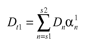
- Übertragungsverfahren nach Anspruch 1, wobei in dem Fall, dass die Anzahl der isolierten Subträger gleich 1 ist, der Wert Dt1 auf dem isolierten Subträger bestimmt wird durch:

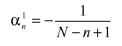
wobei
- Übertragungsverfahren zur Unterdrückung von Zwischenträgerinterferenzen, das Folgendes umfasst:a) Konfigurieren von mindestens einem isolierten Subträger zwischen einem ersten Satz von Subträgem und einem zweiten Satz von Subträgem,b) Bestimmen der Datenwerte auf den isolierten Subträgem derart, dass die aus den isolierten Subträgem resultierende Zwischenträgerinterferenz zu dem zweiten Satz von Subträgem die aus dem ersten Satz von Subträgem resultierende Zwischenträgerinterferenz mit dem zweiten Satz von Subträgem ausgleicht, wobei die Datenwerte auf den isolierten Subträgem auf der Grundlage der gewichteten Summe der Daten auf jedem Subträger des ersten Satzes von Subträgem bestimmt werden, wobei die jedem der Subträger entsprechenden Gewichtungsfaktoren auf der Grundlage bestimmt werden, dass sich die Interferenzeigenschaften zwischen den Subträgem gegenüber dem Trägerfrequenzversatz zwischen dem ersten Satz und dem zweiten Satz von Subträgem ändern, undc) Übertragen der Daten über eine Vielzahl von Subträgem, die den ersten Satz von Subträgem, den zweiten Satz von Subträgem und die isolierten Subträger umfasst, wobei die genannte Änderung der Interferenzeigenschaften zwischen den Subträgem, die in den Koeffizienten für die Interferenz zwischen dem ersten Satz von Subträgem und dem zweiten Satz von Subträgem bestehen, gegenüber dem Frequenzversatz zwischen dem ersten Satz von Subträgem und dem zweiten Satz von Subträgem flach verläuft.
- Übertragungsverfahren nach Anspruch 3, wobei in dem Fall, dass die Anzahl der isolierten Subträger gleich 1 ist, der Wert Dt1 auf dem isolierten Subträger bestimmt wird durch:


wobei
- Übertragungsvorrichtung zur Unterdrückung von Zwischenträgerinterferenzen, die Folgendes umfasst:eine Konfigurationseinheit zum Konfigurieren von mindestens einem isolierten Subträger zwischen einem ersten Satz von Subträgem und einem zweiten Satz von Subträgem,eine Bestimmungseinheit zum Bestimmen der Datenwerte auf den isolierten Subträgem derart, dass die aus den isolierten Subträgem resultierende Zwischenträgerinterferenz zu dem zweiten Satz von Subträgem die aus dem ersten Satz von Subträgem resultierende Zwischenträgerinterferenz mit dem zweiten Satz von Subträgem ausgleicht, wobei die Datenwerte auf den isolierten Subträgem auf der Grundlage der gewichteten Summe der Daten auf jedem Subträger des ersten Satzes von Subträgem bestimmt werden, wobei die jedem der Subträger entsprechenden Gewichtungsfaktoren auf der Grundlage bestimmt werden, dass sich die Interferenzeigenschaften zwischen den Subträgem gegenüber dem Trägerfrequenzversatz zwischen dem ersten Satz und dem zweiten Satz von Subträgem ändern, undeine Übertragungseinheit zum Übertragen der Daten über eine Vielzahl von Subträgem, die den ersten Satz von Subträgem, den zweiten Satz von Subträgem und die isolierten Subträger umfasst,wobei von der genannten Änderung der Interferenzeigenschaften zwischen den Subträgem, die in den Koeffizienten für die Interferenz zwischen dem ersten Satz von Subträgem und dem zweiten Satz von Subträgem bestehen, angenommen wird, dass sie umgekehrt proportional zum Frequenzversatz zwischen dem ersten Satz von Subträgem und dem zweiten Satz von Subträgem ist.
- Übertragungsvorrichtung nach Anspruch 5, wobei in dem Fall, dass die Anzahl der isolierten Subträger gleich 1 ist, der Wert Dt1 auf dem isolierten Subträger bestimmt wird durch:

wobei
- Übertragungsvorrichtung zur Unterdrückung von Zwischenträgerinterferenzen, die Folgendes umfasst:eine Konfigurationseinheit zum Konfigurieren von mindestens einem isolierten Subträger zwischen einem ersten Satz von Subträgem und einem zweiten Satz von Subträgem,eine Bestimmungseinheit zum Bestimmen der Datenwerte auf den isolierten Subträgem derart, dass die aus den isolierten Subträgem resultierende Zwischenträgerinterferenz zu dem zweiten Satz von Subträgem die aus dem ersten Satz von Subträgem resultierende Zwischenträgerinterferenz mit dem zweiten Satz von Subträgem ausgleicht, wobei die Datenwerte auf den isolierten Subträgem auf der Grundlage der gewichteten Summe der Daten auf jedem Subträger des ersten Satzes von Subträgem bestimmt werden, wobei die jedem der Subträger entsprechenden Gewichtungsfaktoren auf der Grundlage bestimmt werden, dass sich die Interferenzeigenschaften zwischen den Subträgem gegenüber dem Trägerfrequenzversatz zwischen dem ersten Satz und dem zweiten Satz von Subträgem ändern, undeine Übertragungseinheit zum Übertragen der Daten über eine Vielzahl von Subträgem, die den ersten Satz von Subträgem, den zweiten Satz von Subträgem und die isolierten Subträger umfasst,wobei die genannte Änderung der Interferenzeigenschaften zwischen den Subträgem, die in den Koeffizienten für die Interferenz zwischen dem ersten Satz von Subträgem und dem zweiten Satz von Subträgem bestehen, gegenüber dem Frequenzversatz zwischen dem ersten Satz von Subträgem und dem zweiten Satz von Subträgem flach verläuft.
- Übertragungsvorrichtung nach Anspruch 7, wobei in dem Fall, dass die Anzahl der isolierten Subträger gleich 1 ist, der Wert Dt1 auf dem isolierten Subträger bestimmt wird durch:


wobei
Applications Claiming Priority (2)
| Application Number | Priority Date | Filing Date | Title |
|---|---|---|---|
| CN200610121323 | 2006-08-21 | ||
| PCT/IB2007/053154 WO2008023299A2 (en) | 2006-08-21 | 2007-08-09 | A transmission method and apparatus for cancelling inter-carrier interference |
Publications (2)
| Publication Number | Publication Date |
|---|---|
| EP2057809A2 EP2057809A2 (de) | 2009-05-13 |
| EP2057809B1 true EP2057809B1 (de) | 2010-05-26 |
Family
ID=38996563
Family Applications (1)
| Application Number | Title | Priority Date | Filing Date |
|---|---|---|---|
| EP07805352A Active EP2057809B1 (de) | 2006-08-21 | 2007-08-09 | Übertragungsverfahren und Vorrichtungen zur Unterdrückung der Interferenzen zwischen Trägern |
Country Status (7)
| Country | Link |
|---|---|
| US (2) | US8520750B2 (de) |
| EP (1) | EP2057809B1 (de) |
| JP (1) | JP5302887B2 (de) |
| CN (1) | CN101507221B (de) |
| AT (1) | ATE469493T1 (de) |
| DE (1) | DE602007006817D1 (de) |
| WO (1) | WO2008023299A2 (de) |
Families Citing this family (14)
| Publication number | Priority date | Publication date | Assignee | Title |
|---|---|---|---|---|
| ATE469493T1 (de) * | 2006-08-21 | 2010-06-15 | Koninkl Philips Electronics Nv | Übertragungsverfahren und vorrichtungen zur unterdrückung der interferenzen zwischen trägern |
| WO2009069088A2 (en) * | 2007-11-30 | 2009-06-04 | Nxp B.V. | Ici cancellation apparatus and method for ofdm systems |
| CN102469590B (zh) * | 2010-11-10 | 2016-08-17 | 南京中兴新软件有限责任公司 | 一种下行干扰协调的方法和装置 |
| CN102238130B (zh) * | 2011-08-05 | 2014-06-18 | 电子科技大学 | 基于ofdm的wdm-pon系统及下行数据传输方法 |
| JP5559759B2 (ja) * | 2011-09-12 | 2014-07-23 | 日本電信電話株式会社 | 無線通信システム、及び無線通信方法 |
| US20130142138A1 (en) * | 2011-12-05 | 2013-06-06 | Esmael Hejazi Dinan | Coordination of Control Channel Transmissions |
| CN105933909A (zh) * | 2012-02-24 | 2016-09-07 | 华为技术有限公司 | 物理小区标识配置、逻辑根序列索引配置方法及基站设备 |
| CN104079306B (zh) * | 2013-03-26 | 2016-08-03 | 华为技术有限公司 | 一种接收机的操作方法和信号接收设备 |
| CN105357160B (zh) | 2014-08-19 | 2020-09-15 | 北京三星通信技术研究有限公司 | 发送参考信号的方法及装置、接收参考信号的方法及装置 |
| CN106998591B (zh) * | 2016-01-24 | 2018-03-23 | 上海朗帛通信技术有限公司 | 一种调度方法和装置 |
| CN109792263B (zh) * | 2016-09-27 | 2021-06-08 | 江苏舒茨测控设备股份有限公司 | 数据传输方法及装置 |
| CN111698185B (zh) * | 2020-06-16 | 2023-05-30 | Oppo广东移动通信有限公司 | 载波干扰消除方法、装置、电子设备及存储介质 |
| US11356856B2 (en) | 2020-07-14 | 2022-06-07 | Motorola Solutions, Inc. | Reallocation of spectral resources in multiwaveform systems |
| CN114337904B (zh) * | 2021-11-29 | 2023-11-14 | 中山大学 | 一种波分复用传输系统中提高信道带宽利用率的方法 |
Family Cites Families (17)
| Publication number | Priority date | Publication date | Assignee | Title |
|---|---|---|---|---|
| FR2671857B1 (fr) | 1991-01-23 | 1994-12-09 | Snecma | Chambre de combustion, notamment pour turbine a gaz, a paroi deformable. |
| JP3112659B2 (ja) * | 1997-05-30 | 2000-11-27 | 株式会社次世代デジタルテレビジョン放送システム研究所 | 周波数ダイバーシティ方式ならびにその送信装置、受信装置 |
| JP2916445B2 (ja) * | 1997-09-03 | 1999-07-05 | 株式会社次世代デジタルテレビジョン放送システム研究所 | 多周波数網方式ならびにその送信装置、中継装置 |
| JP2000224133A (ja) * | 1999-01-28 | 2000-08-11 | Matsushita Electric Ind Co Ltd | 周波数分割多重信号送受信装置と送受信方法 |
| JP3127918B1 (ja) * | 1999-07-14 | 2001-01-29 | 住友電気工業株式会社 | 路車間通信システム並びに路上通信局及び車載移動局 |
| JP3992489B2 (ja) * | 2001-12-12 | 2007-10-17 | 株式会社エヌ・ティ・ティ・ドコモ | 無線通信方法及びその装置 |
| KR100498953B1 (ko) * | 2003-07-08 | 2005-07-04 | 삼성전자주식회사 | 불충분한 주기적 프리픽스를 사용하는 직교 주파수 분할다중화 시스템을 위한 송수신 장치 및 방법 |
| KR100913874B1 (ko) | 2003-10-27 | 2009-08-26 | 삼성전자주식회사 | 직교주파수분할다중 시스템에서 부채널 간 간섭 제거 방법 |
| US8027417B2 (en) * | 2003-12-19 | 2011-09-27 | Nortel Networks Limited | Interference-weighted communication signal processing systems and methods |
| CN1667987B (zh) * | 2004-03-12 | 2011-03-23 | 上海贝尔阿尔卡特股份有限公司 | 自适应通信方法和装置 |
| US7616557B2 (en) | 2004-05-17 | 2009-11-10 | California Institute Of Technology | Method and apparatus for canceling intercarrier interference through conjugate transmission for multicarrier communication systems |
| TWI256219B (en) * | 2004-08-09 | 2006-06-01 | Realtek Semiconductor Corp | Interference alleviation equalizer of multi-carrier communication system and method thereof |
| US7620018B2 (en) * | 2005-02-02 | 2009-11-17 | Samsung Electronics Co., Ltd. | Apparatus and method for a multi-channel orthogonal frequency division multiplexing wireless network |
| US7706428B2 (en) * | 2005-04-21 | 2010-04-27 | Telefonaktiebolaget L M Ericsson (Publ) | Low complexity inter-carrier interference cancellation |
| WO2007088580A1 (ja) * | 2006-01-31 | 2007-08-09 | Mitsubishi Denki Kabushiki Kaisha | 通信制御方法、受信局装置、送信局装置および通信システム |
| JP2007329532A (ja) * | 2006-06-06 | 2007-12-20 | Matsushita Electric Ind Co Ltd | 直交周波数分割多元接続システムおよびその送受信装置 |
| ATE469493T1 (de) * | 2006-08-21 | 2010-06-15 | Koninkl Philips Electronics Nv | Übertragungsverfahren und vorrichtungen zur unterdrückung der interferenzen zwischen trägern |
-
2007
- 2007-08-09 AT AT07805352T patent/ATE469493T1/de not_active IP Right Cessation
- 2007-08-09 DE DE602007006817T patent/DE602007006817D1/de active Active
- 2007-08-09 WO PCT/IB2007/053154 patent/WO2008023299A2/en active Application Filing
- 2007-08-09 US US12/438,161 patent/US8520750B2/en active Active
- 2007-08-09 JP JP2009525137A patent/JP5302887B2/ja active Active
- 2007-08-09 CN CN2007800310326A patent/CN101507221B/zh active Active
- 2007-08-09 EP EP07805352A patent/EP2057809B1/de active Active
-
2013
- 2013-07-31 US US13/955,022 patent/US9374204B2/en active Active
Also Published As
| Publication number | Publication date |
|---|---|
| JP5302887B2 (ja) | 2013-10-02 |
| US9374204B2 (en) | 2016-06-21 |
| US20090252245A1 (en) | 2009-10-08 |
| US8520750B2 (en) | 2013-08-27 |
| US20130308587A1 (en) | 2013-11-21 |
| ATE469493T1 (de) | 2010-06-15 |
| EP2057809A2 (de) | 2009-05-13 |
| WO2008023299A2 (en) | 2008-02-28 |
| DE602007006817D1 (de) | 2010-07-08 |
| CN101507221A (zh) | 2009-08-12 |
| CN101507221B (zh) | 2013-07-24 |
| WO2008023299A3 (en) | 2008-05-08 |
| JP2010502078A (ja) | 2010-01-21 |
Similar Documents
| Publication | Publication Date | Title |
|---|---|---|
| EP2057809B1 (de) | Übertragungsverfahren und Vorrichtungen zur Unterdrückung der Interferenzen zwischen Trägern | |
| US7715492B2 (en) | Transmitter and transmission method | |
| US8582548B2 (en) | Frequency division multiple access schemes for wireless communication | |
| US8077692B2 (en) | Enhanced frequency division multiple access for wireless communication | |
| US7948868B2 (en) | Method and arrangement relating to the insertion of pilot tones in the frequency domain in SC-FDMA | |
| US9240910B2 (en) | Out-of-band emission cancellation | |
| US20080080627A1 (en) | Controlling filter in connection with cyclic transmission format | |
| US20100220797A1 (en) | Communication apparatus | |
| KR20160088792A (ko) | 필터 뱅크 멀티 캐리어 변조 기반의 통신 방법 및 장치 | |
| US8396145B2 (en) | Method and device for notching the transmission band of an analog signal, in particular for a detect and avoid (DAA) operation mode of an MB-OFDM system | |
| JP2002271293A (ja) | 受信装置、受信方法、プログラム、ならびに、情報記録媒体 | |
| EP2353265B1 (de) | Verfahren für papr optimierung in daten für übertragung und verfahren für datenübertragung | |
| US7346041B2 (en) | Processing of an OFDM signal | |
| WO2020105481A1 (ja) | 送信装置および送信方法 | |
| JP4874178B2 (ja) | 無線送信方法、伝搬路推定方法、無線送信機、無線受信機および無線通信システム | |
| Levy et al. | Filter bank multi carrier modulation performance | |
| Aldinger | A multicarrier scheme for HIPERLAN | |
| Yoshito et al. | A Frequency-domain ICI Cancellation Using Weight Matrix Based on Window Shape for Simplified UTW-OFDM | |
| Dewangan | A detailed Study of 4G in Wireless Communication: Looking insight in issues in OFDM | |
| WO2018110279A1 (ja) | 送信装置、送信方法、受信装置および受信方法 | |
| Wei et al. | Performance analysize of joint processing of sidelobe suppression and PAPR reduction in NC-OFDM systems | |
| WO2009069088A2 (en) | Ici cancellation apparatus and method for ofdm systems |
Legal Events
| Date | Code | Title | Description |
|---|---|---|---|
| PUAI | Public reference made under article 153(3) epc to a published international application that has entered the european phase |
Free format text: ORIGINAL CODE: 0009012 |
|
| 17P | Request for examination filed |
Effective date: 20090323 |
|
| AK | Designated contracting states |
Kind code of ref document: A2 Designated state(s): AT BE BG CH CY CZ DE DK EE ES FI FR GB GR HU IE IS IT LI LT LU LV MC MT NL PL PT RO SE SI SK TR |
|
| AX | Request for extension of the european patent |
Extension state: AL BA HR MK RS |
|
| 17Q | First examination report despatched |
Effective date: 20090713 |
|
| DAX | Request for extension of the european patent (deleted) | ||
| GRAP | Despatch of communication of intention to grant a patent |
Free format text: ORIGINAL CODE: EPIDOSNIGR1 |
|
| RTI1 | Title (correction) |
Free format text: TRANSMISSION METHODS AND APPARATUSES FOR CANCELLING INTER-CARRIER INTERFERENCE |
|
| RTI1 | Title (correction) |
Free format text: TRANSMISSION METHODS AND APPARATUSES FOR CANCELLING INTER-CARRIER INTERFERENCE |
|
| RTI1 | Title (correction) |
Free format text: TRANSMISSION METHODS AND APPARATUSES FOR CANCELLING INTER-CARRIER INTERFERENCE |
|
| GRAS | Grant fee paid |
Free format text: ORIGINAL CODE: EPIDOSNIGR3 |
|
| GRAA | (expected) grant |
Free format text: ORIGINAL CODE: 0009210 |
|
| AK | Designated contracting states |
Kind code of ref document: B1 Designated state(s): AT BE BG CH CY CZ DE DK EE ES FI FR GB GR HU IE IS IT LI LT LU LV MC MT NL PL PT RO SE SI SK TR |
|
| REG | Reference to a national code |
Ref country code: GB Ref legal event code: FG4D |
|
| REG | Reference to a national code |
Ref country code: CH Ref legal event code: EP |
|
| REG | Reference to a national code |
Ref country code: IE Ref legal event code: FG4D |
|
| REF | Corresponds to: |
Ref document number: 602007006817 Country of ref document: DE Date of ref document: 20100708 Kind code of ref document: P |
|
| REG | Reference to a national code |
Ref country code: NL Ref legal event code: VDEP Effective date: 20100526 |
|
| LTIE | Lt: invalidation of european patent or patent extension |
Effective date: 20100526 |
|
| PG25 | Lapsed in a contracting state [announced via postgrant information from national office to epo] |
Ref country code: SE Free format text: LAPSE BECAUSE OF FAILURE TO SUBMIT A TRANSLATION OF THE DESCRIPTION OR TO PAY THE FEE WITHIN THE PRESCRIBED TIME-LIMIT Effective date: 20100526 Ref country code: LT Free format text: LAPSE BECAUSE OF FAILURE TO SUBMIT A TRANSLATION OF THE DESCRIPTION OR TO PAY THE FEE WITHIN THE PRESCRIBED TIME-LIMIT Effective date: 20100526 |
|
| PG25 | Lapsed in a contracting state [announced via postgrant information from national office to epo] |
Ref country code: SI Free format text: LAPSE BECAUSE OF FAILURE TO SUBMIT A TRANSLATION OF THE DESCRIPTION OR TO PAY THE FEE WITHIN THE PRESCRIBED TIME-LIMIT Effective date: 20100526 Ref country code: LV Free format text: LAPSE BECAUSE OF FAILURE TO SUBMIT A TRANSLATION OF THE DESCRIPTION OR TO PAY THE FEE WITHIN THE PRESCRIBED TIME-LIMIT Effective date: 20100526 Ref country code: IS Free format text: LAPSE BECAUSE OF FAILURE TO SUBMIT A TRANSLATION OF THE DESCRIPTION OR TO PAY THE FEE WITHIN THE PRESCRIBED TIME-LIMIT Effective date: 20100926 Ref country code: FI Free format text: LAPSE BECAUSE OF FAILURE TO SUBMIT A TRANSLATION OF THE DESCRIPTION OR TO PAY THE FEE WITHIN THE PRESCRIBED TIME-LIMIT Effective date: 20100526 Ref country code: AT Free format text: LAPSE BECAUSE OF FAILURE TO SUBMIT A TRANSLATION OF THE DESCRIPTION OR TO PAY THE FEE WITHIN THE PRESCRIBED TIME-LIMIT Effective date: 20100526 |
|
| PG25 | Lapsed in a contracting state [announced via postgrant information from national office to epo] |
Ref country code: CY Free format text: LAPSE BECAUSE OF FAILURE TO SUBMIT A TRANSLATION OF THE DESCRIPTION OR TO PAY THE FEE WITHIN THE PRESCRIBED TIME-LIMIT Effective date: 20100609 Ref country code: PL Free format text: LAPSE BECAUSE OF FAILURE TO SUBMIT A TRANSLATION OF THE DESCRIPTION OR TO PAY THE FEE WITHIN THE PRESCRIBED TIME-LIMIT Effective date: 20100526 |
|
| PG25 | Lapsed in a contracting state [announced via postgrant information from national office to epo] |
Ref country code: NL Free format text: LAPSE BECAUSE OF FAILURE TO SUBMIT A TRANSLATION OF THE DESCRIPTION OR TO PAY THE FEE WITHIN THE PRESCRIBED TIME-LIMIT Effective date: 20100526 Ref country code: PT Free format text: LAPSE BECAUSE OF FAILURE TO SUBMIT A TRANSLATION OF THE DESCRIPTION OR TO PAY THE FEE WITHIN THE PRESCRIBED TIME-LIMIT Effective date: 20100927 Ref country code: DK Free format text: LAPSE BECAUSE OF FAILURE TO SUBMIT A TRANSLATION OF THE DESCRIPTION OR TO PAY THE FEE WITHIN THE PRESCRIBED TIME-LIMIT Effective date: 20100526 Ref country code: EE Free format text: LAPSE BECAUSE OF FAILURE TO SUBMIT A TRANSLATION OF THE DESCRIPTION OR TO PAY THE FEE WITHIN THE PRESCRIBED TIME-LIMIT Effective date: 20100526 |
|
| PG25 | Lapsed in a contracting state [announced via postgrant information from national office to epo] |
Ref country code: BE Free format text: LAPSE BECAUSE OF FAILURE TO SUBMIT A TRANSLATION OF THE DESCRIPTION OR TO PAY THE FEE WITHIN THE PRESCRIBED TIME-LIMIT Effective date: 20100526 Ref country code: RO Free format text: LAPSE BECAUSE OF FAILURE TO SUBMIT A TRANSLATION OF THE DESCRIPTION OR TO PAY THE FEE WITHIN THE PRESCRIBED TIME-LIMIT Effective date: 20100526 Ref country code: SK Free format text: LAPSE BECAUSE OF FAILURE TO SUBMIT A TRANSLATION OF THE DESCRIPTION OR TO PAY THE FEE WITHIN THE PRESCRIBED TIME-LIMIT Effective date: 20100526 Ref country code: CZ Free format text: LAPSE BECAUSE OF FAILURE TO SUBMIT A TRANSLATION OF THE DESCRIPTION OR TO PAY THE FEE WITHIN THE PRESCRIBED TIME-LIMIT Effective date: 20100526 |
|
| PG25 | Lapsed in a contracting state [announced via postgrant information from national office to epo] |
Ref country code: IT Free format text: LAPSE BECAUSE OF FAILURE TO SUBMIT A TRANSLATION OF THE DESCRIPTION OR TO PAY THE FEE WITHIN THE PRESCRIBED TIME-LIMIT Effective date: 20100526 Ref country code: MC Free format text: LAPSE BECAUSE OF NON-PAYMENT OF DUE FEES Effective date: 20100831 |
|
| PLBE | No opposition filed within time limit |
Free format text: ORIGINAL CODE: 0009261 |
|
| STAA | Information on the status of an ep patent application or granted ep patent |
Free format text: STATUS: NO OPPOSITION FILED WITHIN TIME LIMIT |
|
| 26N | No opposition filed |
Effective date: 20110301 |
|
| PG25 | Lapsed in a contracting state [announced via postgrant information from national office to epo] |
Ref country code: GR Free format text: LAPSE BECAUSE OF FAILURE TO SUBMIT A TRANSLATION OF THE DESCRIPTION OR TO PAY THE FEE WITHIN THE PRESCRIBED TIME-LIMIT Effective date: 20100827 |
|
| REG | Reference to a national code |
Ref country code: DE Ref legal event code: R097 Ref document number: 602007006817 Country of ref document: DE Effective date: 20110301 Ref country code: DE Ref legal event code: R097 Ref document number: 602007006817 Country of ref document: DE Effective date: 20110228 |
|
| REG | Reference to a national code |
Ref country code: DE Ref legal event code: R119 Ref document number: 602007006817 Country of ref document: DE Effective date: 20110301 |
|
| PG25 | Lapsed in a contracting state [announced via postgrant information from national office to epo] |
Ref country code: IE Free format text: LAPSE BECAUSE OF NON-PAYMENT OF DUE FEES Effective date: 20100809 Ref country code: DE Free format text: LAPSE BECAUSE OF NON-PAYMENT OF DUE FEES Effective date: 20110301 |
|
| PG25 | Lapsed in a contracting state [announced via postgrant information from national office to epo] |
Ref country code: MT Free format text: LAPSE BECAUSE OF FAILURE TO SUBMIT A TRANSLATION OF THE DESCRIPTION OR TO PAY THE FEE WITHIN THE PRESCRIBED TIME-LIMIT Effective date: 20100526 |
|
| REG | Reference to a national code |
Ref country code: CH Ref legal event code: PL |
|
| PG25 | Lapsed in a contracting state [announced via postgrant information from national office to epo] |
Ref country code: LI Free format text: LAPSE BECAUSE OF NON-PAYMENT OF DUE FEES Effective date: 20110831 Ref country code: CH Free format text: LAPSE BECAUSE OF NON-PAYMENT OF DUE FEES Effective date: 20110831 |
|
| PG25 | Lapsed in a contracting state [announced via postgrant information from national office to epo] |
Ref country code: BG Free format text: LAPSE BECAUSE OF FAILURE TO SUBMIT A TRANSLATION OF THE DESCRIPTION OR TO PAY THE FEE WITHIN THE PRESCRIBED TIME-LIMIT Effective date: 20100526 Ref country code: HU Free format text: LAPSE BECAUSE OF FAILURE TO SUBMIT A TRANSLATION OF THE DESCRIPTION OR TO PAY THE FEE WITHIN THE PRESCRIBED TIME-LIMIT Effective date: 20101127 Ref country code: LU Free format text: LAPSE BECAUSE OF NON-PAYMENT OF DUE FEES Effective date: 20100809 |
|
| PG25 | Lapsed in a contracting state [announced via postgrant information from national office to epo] |
Ref country code: TR Free format text: LAPSE BECAUSE OF FAILURE TO SUBMIT A TRANSLATION OF THE DESCRIPTION OR TO PAY THE FEE WITHIN THE PRESCRIBED TIME-LIMIT Effective date: 20100526 |
|
| PG25 | Lapsed in a contracting state [announced via postgrant information from national office to epo] |
Ref country code: BG Free format text: LAPSE BECAUSE OF FAILURE TO SUBMIT A TRANSLATION OF THE DESCRIPTION OR TO PAY THE FEE WITHIN THE PRESCRIBED TIME-LIMIT Effective date: 20100826 |
|
| PG25 | Lapsed in a contracting state [announced via postgrant information from national office to epo] |
Ref country code: ES Free format text: LAPSE BECAUSE OF FAILURE TO SUBMIT A TRANSLATION OF THE DESCRIPTION OR TO PAY THE FEE WITHIN THE PRESCRIBED TIME-LIMIT Effective date: 20100906 |
|
| REG | Reference to a national code |
Ref country code: FR Ref legal event code: CD Owner name: KONINKLIJKE PHILIPS ELECTRONICS N.V., NL Effective date: 20141126 Ref country code: FR Ref legal event code: CA Effective date: 20141126 |
|
| REG | Reference to a national code |
Ref country code: FR Ref legal event code: PLFP Year of fee payment: 10 |
|
| REG | Reference to a national code |
Ref country code: FR Ref legal event code: PLFP Year of fee payment: 11 |
|
| REG | Reference to a national code |
Ref country code: FR Ref legal event code: PLFP Year of fee payment: 12 |
|
| PGFP | Annual fee paid to national office [announced via postgrant information from national office to epo] |
Ref country code: GB Payment date: 20230822 Year of fee payment: 17 |
|
| PGFP | Annual fee paid to national office [announced via postgrant information from national office to epo] |
Ref country code: FR Payment date: 20230824 Year of fee payment: 17 |