EP2057418B1 - Geräteblende - Google Patents
Geräteblende Download PDFInfo
- Publication number
- EP2057418B1 EP2057418B1 EP07788134.0A EP07788134A EP2057418B1 EP 2057418 B1 EP2057418 B1 EP 2057418B1 EP 07788134 A EP07788134 A EP 07788134A EP 2057418 B1 EP2057418 B1 EP 2057418B1
- Authority
- EP
- European Patent Office
- Prior art keywords
- cover
- appliance
- particles
- display
- light
- Prior art date
- Legal status (The legal status is an assumption and is not a legal conclusion. Google has not performed a legal analysis and makes no representation as to the accuracy of the status listed.)
- Active
Links
- 239000002245 particle Substances 0.000 claims description 20
- 239000000463 material Substances 0.000 claims description 13
- 238000001746 injection moulding Methods 0.000 claims description 10
- 238000000034 method Methods 0.000 claims description 9
- 238000004519 manufacturing process Methods 0.000 claims description 8
- 239000003795 chemical substances by application Substances 0.000 claims 4
- 239000011888 foil Substances 0.000 claims 1
- 229920003023 plastic Polymers 0.000 description 6
- 238000005286 illumination Methods 0.000 description 5
- 239000003086 colorant Substances 0.000 description 3
- 238000005516 engineering process Methods 0.000 description 3
- 238000007639 printing Methods 0.000 description 3
- BQCADISMDOOEFD-UHFFFAOYSA-N Silver Chemical compound [Ag] BQCADISMDOOEFD-UHFFFAOYSA-N 0.000 description 2
- 238000001816 cooling Methods 0.000 description 2
- 230000000694 effects Effects 0.000 description 2
- 239000000049 pigment Substances 0.000 description 2
- 229910052709 silver Inorganic materials 0.000 description 2
- 239000004332 silver Substances 0.000 description 2
- 230000004913 activation Effects 0.000 description 1
- RHZUVFJBSILHOK-UHFFFAOYSA-N anthracen-1-ylmethanolate Chemical compound C1=CC=C2C=C3C(C[O-])=CC=CC3=CC2=C1 RHZUVFJBSILHOK-UHFFFAOYSA-N 0.000 description 1
- 239000003830 anthracite Substances 0.000 description 1
- 238000000149 argon plasma sintering Methods 0.000 description 1
- 238000004140 cleaning Methods 0.000 description 1
- 239000011248 coating agent Substances 0.000 description 1
- 238000000576 coating method Methods 0.000 description 1
- 238000005034 decoration Methods 0.000 description 1
- 230000001419 dependent effect Effects 0.000 description 1
- 238000010017 direct printing Methods 0.000 description 1
- 230000003670 easy-to-clean Effects 0.000 description 1
- 230000003628 erosive effect Effects 0.000 description 1
- 230000003760 hair shine Effects 0.000 description 1
- 239000012535 impurity Substances 0.000 description 1
- 238000003780 insertion Methods 0.000 description 1
- 230000037431 insertion Effects 0.000 description 1
- 239000000203 mixture Substances 0.000 description 1
- 230000019612 pigmentation Effects 0.000 description 1
- 230000003678 scratch resistant effect Effects 0.000 description 1
- MZFIXCCGFYSQSS-UHFFFAOYSA-N silver titanium Chemical compound [Ti].[Ag] MZFIXCCGFYSQSS-UHFFFAOYSA-N 0.000 description 1
- 238000001228 spectrum Methods 0.000 description 1
- 229910001220 stainless steel Inorganic materials 0.000 description 1
- 239000010935 stainless steel Substances 0.000 description 1
- 239000012780 transparent material Substances 0.000 description 1
Images

Classifications
-
- H—ELECTRICITY
- H01—ELECTRIC ELEMENTS
- H01H—ELECTRIC SWITCHES; RELAYS; SELECTORS; EMERGENCY PROTECTIVE DEVICES
- H01H9/00—Details of switching devices, not covered by groups H01H1/00 - H01H7/00
- H01H9/18—Distinguishing marks on switches, e.g. for indicating switch location in the dark; Adaptation of switches to receive distinguishing marks
- H01H9/182—Illumination of the symbols or distinguishing marks
-
- F—MECHANICAL ENGINEERING; LIGHTING; HEATING; WEAPONS; BLASTING
- F24—HEATING; RANGES; VENTILATING
- F24C—DOMESTIC STOVES OR RANGES ; DETAILS OF DOMESTIC STOVES OR RANGES, OF GENERAL APPLICATION
- F24C7/00—Stoves or ranges heated by electric energy
- F24C7/08—Arrangement or mounting of control or safety devices
- F24C7/082—Arrangement or mounting of control or safety devices on ranges, e.g. control panels, illumination
Definitions
- the invention relates to a device panel with the features of the preamble of claim 1, and a method for producing such a panel.
- Blends produced in this way are used, for example, as a control and / or function display for appliances from household technology.
- conventional screens usually have dots, illuminated areas and symbols which light up depending on the operation or device status.
- a window with a diffuser film or a light guide with diffuser particles is usually inserted into the apertures.
- structures in particular microstructures, are also applied to the front of a transparent plastic display window facing away from the interior of the device.
- a transparent plastic display window facing away from the interior of the device.
- Such a device panel is from the JP 2004 090626 A known.
- the present invention is therefore an object of the invention to provide a screen for a display, in particular for an LED display, and a manufacturing method, which is to manufacture in the simplest and most cost-effective manner and ensures uniform scattering of an incident light of a light source.
- the particle size can be adapted to the prevailing conditions, such as wavelength of light and aperture thickness, so that a uniform illumination of the display area is achieved by the light scattering on the particles.
- the particles preferably have an average diameter of 1 to 5 microns, especially about 3 microns.
- the material of the control surface in the area of the luminous surface is transparent, for example, as a transparent or colorless plastic such as SAN or Luran, designed so that for the control and / or function display, so the display areas, desired different colors by a correspondingly printed ink layer, for example a color film, can be produced.
- a printed color film according to the so-called IMD technique Inner Mold Decoration
- IMD technique Inner Mold Decoration
- the luminous surfaces or the display areas form an aligned unit with the rest of the material of the panel or are integrated in this, so that advantageously no edges or joints on the upper or outer surface, ie at the in-installed state of the device interior facing away from the front panel of the diaphragm, in which impurities could arise, so that the surface of the diaphragm can be cleaned while avoiding such edges or moving parts in a simple manner.
- operating elements can be realized for example as a touch control.
- the device panel is formed integrally with their display area or their display areas.
- the top layer of the panel can also be designed as anti-scratch coating, so that advantageously creates a scratch-resistant and easy-to-clean surface.
- the luminous surfaces can be omitted in color printing, so that any shapes, such as rectangles, dots and symbols in positive or negative printing are easy to implement. Even a mirroring of the luminous surfaces is possible by applying a transparent silver color printing, so that a light display or a display area is mirrored and only becomes visible when lighting up.
- color particles or pigments can be added to the transparent material as particles, so that the display area itself appears in the switched-off state, ie without light, in, for example, dark color, or the appearance of a switched-off display area can be set in a desired color.
- the aperture is made of plastic.
- the diaphragm can be produced particularly easily by an injection molding process, wherein the particles are added to the material before or during the injection molding process.
- the interior of the device facing rear of the device panel is structured at least in the display area, so that in combination with the addition of particles, the scattering effect and thus the uniformity of the illumination can be further improved.
- a structure may be applied to make the bottom of the panel structured in a simple and cost-effective manner.
- the dimensions of this structure can be adapted to the wavelength of the light source. In this way, the scattering of a high proportion of the light emitted by the light source can be achieved.
- this structure is a structure in the micrometer range, a so-called microstructure.
- the structure can be achieved, for example, by targeted erosion of the core surface of the injection molding tool.
- inventive method for producing can be dispensed with in any embodiments of the invention on the use of additional parts such as light guides, diffuser films or diffuser prints without the desired uniform illumination of the luminous or luminous surfaces suffers hereunder.
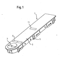
- Fig. 1 an aperture 1 according to the invention is shown, which has a substantially flat base surface 3.
- vertical projections 5 are formed in the form of walls and locking elements, which serve for insertion into a recess provided for this purpose, for example, a freezer.
- the panel 1 control and / or function displays in different shape and color.
- the function display or the operating element 7 is designed to display and / or activate a cooling unit as a circular area, whereas the displays 9 and 11 are formed for example as rectangular symbols.
- Fig. 2 is the panel 1 of a refrigerator, such as a fridge freezer, in addition to those already in Fig. 1 illustrated and explained above display or operating elements 7, 9 and 11 are provided with additional displays 13, for example, to display the actual temperature in ° C both in the cooling area (lower row “2" to "8") and in the freezer area (upper row “-26" to "-18").
- additional displays 13 for example, to display the actual temperature in ° C both in the cooling area (lower row “2" to "8") and in the freezer area (upper row “-26" to "-18").
- logos can be found inside this display, for example in the display 9 "Super” and “Alarm”, in the display 11 “Super” and in the display 7 “Cooler” and “Freezer”, as well as the numbers 2-8 -26 to -18 be designed as a luminous area or display areas, which light up depending on the function and operation.
- These display areas appear through the inventive design, namely admixture of particles, in particular color particles, when illuminated in a desired color and uniform illumination to indicate the respective display and the state (for example, temperature).
- the panel 1 according to the invention and the production method according to the invention for this panel require no structuring of the surface of the panel, it is possible, for example, by means of IMD method, direct printing, etc. to make the surface in desired colors or, for example, by a multi-layered multi-colored structure.
- the diaphragm according to the invention can have operating buttons with touch operation, so that gaps and joints for moving parts can be avoided in order to allow easy cleaning and to avoid functional failures.
- the displays or buttons 7, 9, 11, 13 and plastic for example, as a spherical survey form, which is possible even when using the aforementioned IMD technology to a limited extent.
- the panel it is possible to form the panel as a whole or curved in some areas.
Landscapes
- Engineering & Computer Science (AREA)
- Chemical & Material Sciences (AREA)
- Combustion & Propulsion (AREA)
- Mechanical Engineering (AREA)
- General Engineering & Computer Science (AREA)
- Illuminated Signs And Luminous Advertising (AREA)
- Injection Moulding Of Plastics Or The Like (AREA)
- Details Of Rigid Or Semi-Rigid Containers (AREA)
Description
- Die Erfindung bezieht sich auf eine Geräteblende mit den Merkmalen des Oberbegriffs des Anspruchs 1, sowie ein Verfahren zur Herstellung einer solchen Blende.
- Derartig hergestellte Blenden werden beispielsweise als Bedien- und/oder Funktionsanzeige für Geräte aus der Haushaltstechnik verwendet.
- Hierbei weisen herkömmliche Blenden üblicherweise Punkte, Leuchtflächen und Symbole auf, welche je nach Bedienung oder Gerätezustand aufleuchten.
- Hierbei ist eine möglichst gleichmäßige Ausleuchtung erwünscht. Um das Licht einer meist stark konzentrierten oder gar punktförmigen Lichtquelle, insbesondere einer LED, zu streuen, wird üblicherweise ein Fenster mit einer Diffusorfolie oder ein Lichtleiter mit Diffusorpartikeln in die Blendenöffnungen eingesetzt.
- Weiterhin werden zum Erreichen einer gewünschten Streuwirkung auch Strukturen, insbesondere Mikrostrukturen, auf die dem Geräteinneren abgewandte Vorderseite eines transparenten Kunststoffanzeigefensters aufgebracht. Eine solche Geräteblende ist aus dem
JP 2004 090626 A - Diese Maßnahmen erfordern jedoch einen Mehraufwand an Material oder Arbeitsschritten und sind daher nachteiligerweise zeit- und kostenintensiv.
- Der vorliegenden Erfindung liegt daher die Aufgabe zugrunde, eine Blende für eine Anzeige, insbesondere für eine LED-Anzeige, sowie ein Herstellungsverfahren zu schaffen, welche auf möglichst einfache und kostengünstige Art und Weise herzustellen ist und eine gleichmäßige Streuung eines einfallenden Lichts eines Leuchtmittels gewährleistet.
- Diese Aufgabe wird erfindungsgemäß durch eine Geräteblende mit den Merkmalen des Anspruchs 1, sowie durch ein Verfahren zur Herstellung einer solchen Blende mit den Merkmalen des Anspruchs 8 gelöst.
- Je nach verwendeter Lichtquelle kann die Partikelgröße an die vorliegenden Bedingungen, wie Lichtwellenlänge und Blendendicke, angepasst werden, so dass durch die Lichtstreuung an den Partikeln eine gleichmäßige Ausleuchtung des Anzeigebereichs erzielt wird. Für das verwendete Lichtspektrum im sichtbaren Bereich haben die Partikel bevorzugt einen mittleren Durchmesser von 1 bis 5 Mikrometer, insbesondere etwa 3 Mikrometer.
- In bevorzugter Ausgestaltung der Erfindung ist das Material der Bedienfläche im Bereich der Leuchtfläche transparent, beispielsweise als transparenter bzw. farbloser Kunststoff wie SAN oder Luran, ausgebildet, so dass für die Bedien- und/oder Funktionsanzeige, also die Anzeigebereiche, gewünschte unterschiedliche Farben durch eine entsprechend bedruckte Farbschicht, beispielsweise eine Farbfolie, erzeugt werden können. Hierzu kann beispielsweise eine bedruckte Farbfolie nach der sogenannten IMD-Technik (Inner Mould Decoration) mit Kunststoff hinterspritzt werden.
- In weiterer Ausgestaltung der Erfindung bilden die Leuchtflächen bzw. die Anzeigebereiche eine fluchtende Einheit mit dem übrigen Material der Blende oder sind in dieser integriert, so dass vorteilhafterweise keine Kanten oder Fugen an der Ober- bzw. Außenfläche, also an der im eingebauten Zustand dem Geräteinneren abgewandten Vorderseite der Blende entstehen, in welchen Verunreinigungen entstehen könnten, so dass die Oberfläche der Blende unter Vermeidung von derartigen Kanten oder beweglichen Teilen auf einfache Weise gereinigt werden kann. In dieser Ausgestaltung können Bedienelemente beispielsweise als Touchbedienung realisiert werden. Insbesondere ist daher die Geräteblende mit ihrem Anzeigebereich bzw. ihren Anzeigebereichen einstückig ausgebildet.
- Bei Anwendung der IMD-Technik und einem mehrschichtigen Aufbau kann die oberste Schicht der Blende zudem auch als Antikratzbeschichtung ausgeführt werden, so dass vorteilhafterweise eine kratzfeste und einfach zu reinigende Oberfläche entsteht.
- Bei der Herstellung in der IMD-Technik können die Leuchtflächen im Farbdruck ausgespart werden, so dass beliebige Formen, wie Rechtecke, Punkte und Symbole in Positiv- oder Negativdruck leicht zu realisieren sind. Selbst eine Verspiegelung der Leuchtflächen ist durch Aufbringen eines transparenten Silberfarbdrucks möglich, so dass eine Leuchtanzeige bzw. ein Anzeigebereich verspiegelt ist und erst beim Aufleuchten sichtbar wird.
- In weiterer Ausgestaltung der Erfindung können dem transparenten Material als Partikel Farbpartikel bzw. Pigmente beigemengt werden, so dass der Anzeigebereich selbst im ausgeschalteten Zustand, also ohne Licht, in beispielsweise dunkler Farbe erscheint bzw. das Erscheinungsbild eines ausgeschalteten Anzeigebereichs in einer gewünschten Farbe einstellbar ist.
- Vorzugsweise ist die Blende aus Kunststoff gefertigt. Die Blende kann besonders leicht durch ein Spritzgussverfahren hergestellt werden, wobei dem Material die Partikel vor oder bei dem Spritzgussverfahren beigemengt werden.
- In bevorzugter Ausgestaltung der Erfindung ist die dem Geräteinneren zugewandte Rückseite der Geräteblende zumindest in dem Anzeigebereich strukturiert ausgebildet, so dass in Kombination mit der Beimengung von Partikeln die Streuwirkung und damit die Gleichmäßigkeit der Ausleuchtung weiter verbessert werden kann. Hierzu kann beispielsweise im Spritzgussverfahren auf einer Kernoberfläche eines Spritzwerkzeuges eine Struktur aufgebracht sein, um die Unterseite der Blende auf einfache und kostengünstige Weise strukturiert zu gestalten. Die Abmessungen dieser Struktur können an die Wellenlänge der Lichtquelle angepasst sein. Auf diese Weise kann die Streuung eines hohen Anteils des von der Lichtquelle emittierte Lichts erzielt werden. Insbesondere handelt sich es bei dieser Struktur um eine Struktur im Mikrometerbereich, eine sogenannte Mikrostruktur. Die Struktur kann beispielsweise durch gezielte Erodierung der Kernoberfläche des Spritzgusswerkzeugs erzielt werden.
- Nach dem erfindungsgemäßen Verfahren zur Herstellung kann in den beliebigen Ausgestaltungen der Erfindung auf die Verwendung von zusätzlichen Teilen wie Lichtleiter, Diffusorfolien oder Diffusordrucke verzichtet werden, ohne dass die gewünschte gleichmäßige Ausleuchtung der Leuchtfläche bzw. Leuchtflächen hierunter leidet.
- Weitere Vorteile der Erfindung ergeben sich aus den Unteransprüchen.
- Die Erfindung wird nachfolgend anhand eines in der Zeichnung dargestellten Ausführungsbeispiels näher erläutert.
- In der Zeichnung zeigen:
- Fig. 1
- eine perspektivische Ansicht einer Blende nach der Erfindung und
- Fig. 2
- eine Draufsicht auf eine Oberfläche einer Blende nach
Fig. 1 . - In
Fig. 1 ist eine Blende 1 nach der Erfindung dargestellt, welche eine im Wesentlichen ebene Grundfläche 3 aufweist. An der Unterseite der Grundfläche 3 sind senkrechte Vorsprünge 5 in Form von Wandungen und Rastelementen angeformt, welche dem Einsetzen in eine hierfür vorgesehene Ausnehmung eines Gerätes, beispielsweise eines Gefrierschrankes, dienen. An der Oberseite bzw. an der einer eingebauten Geräteblende dem Geräteinneren abgewandten Vorderseite der Grundfläche 3 weist die Blende 1 Bedien- und/oder Funktionsanzeigen in unterschiedlicher Form und Farbgebung auf. - So ist die Funktionsanzeige bzw. das Bedienelement 7 für das Anzeigen und/oder Aktivieren eines Kühlaggregats als Kreisfläche ausgeführt, wohingegen die Anzeigen 9 und 11 beispielsweise als rechteckige Symbole ausgebildet sind.
- Wie in
Fig. 2 dargestellt, ist die Blende 1 eines Kühlgerätes, beispielsweise einer Kühl-/Gefrierkombination, zusätzlich zu den bereits inFig. 1 dargestellten und vorstehend erläuterten Anzeige- bzw. Bedienelementen 7, 9 und 11 mit zusätzlichen Anzeigen 13 versehen, um beispielsweise die Ist-Temperatur in °C sowohl im Kühlbereich (untere Reihe "2" bis "8") und im Gefrierbereich (obere Reihe "-26" bis "-18") anzuzeigen. - Im Inneren dieser Anzeige können zusätzlich Schriftzüge, wie beispielsweise in der Anzeige 9 "Super" und "Alarm", in der Anzeige 11 "Super" und in der Anzeige 7 "Cooler" und "Freezer", sowie die Zahlen 2-8 bzw. -26 bis -18 als Leuchtfläche bzw. Anzeigebereiche ausgebildet sein, welche je nach Funktion und Bedienung aufleuchten. Diese Anzeigebereiche erscheinen durch die erfindungsgemäße Ausbildung, nämlich Beimengung von Partikeln, insbesondere Farbpartikeln, bei Erleuchten in einer gewünschten Farbe und gleichmäßiger Ausleuchtung, um die jeweilige Anzeige und den Zustand (beispielsweise Temperatur) anzuzeigen.
- Da die erfindungsgemäße Blende 1 und das erfindungsgemäße Herstellverfahren für diese Blende keine Strukturierung der Oberfläche der Blende erfordern, ist es möglich, beispielsweise mittels IMD-Verfahren, direktem Bedrucken, etc. die Oberfläche in gewünschten Farben bzw. beispielsweise durch einen Mehrschichtaufbau mehrfarbig zu gestalten. So kann beispielsweise die die vorstehend erläuterten Anzeigen umgebende Fläche der Oberfläche 15 in Edelstahlsilber, die Anzeigen 11 und 9 in Titansilber und die Anzeigen 13 in Anthrazitgrau, also unterschiedlichen Farben, ausgeführt sein.
- Innerhalb dieser Anzeigen können die Leuchtflächen im nicht erleuchteten Zustand transparent oder durch Beimengung von Pigmenten, also Farbpartikeln, bei der Herstellung in den transparenten Kunststoff auch farbig, also beispielsweise dunkelgelb, erscheinen. Erst bei entsprechendem Leuchten einer bestimmten Leuchtfläche wird deren Aktivierung einem Bediener durch ein helleres Licht oder bei Farbpigmentierung durch die entsprechende Farbe, beispielsweise helles Gelb, angezeigt.
- Hierbei kann die erfindungsgemäße Blende Bedientasten mit Touchbedienung aufweisen, so dass Spalten und Fugen für bewegte Teile vermieden werden können, um eine einfache Reinigung zu ermöglichen und Funktionsausfälle zu vermeiden.
- Selbstverständlich ist es denkbar, trotz im Wesentlichen ebener Ausbildung die Anzeigen bzw. Bedientasten 7, 9, 11, 13 auch plastisch, beispielsweise als kugelförmige Erhebung, auszubilden, was selbst bei Verwendung der vorgenannten IMD-Technik in begrenztem Umfang möglich ist. Ebenso ist es möglich, die Blende insgesamt oder in Teilbereichen gekrümmt auszubilden.
-
- 1
- Geräteblende
- 3
- Grundfläche
- 5
- senkrechte Vorsprünge
- 7
- Anzeige mit Anzeigebereich
- 9
- Anzeige mit Anzeigebereich
- 11
- Anzeige mit Anzeigebereich
- 13
- Anzeige mit Anzeigebereich
- 15
- Oberfläche bzw. Vorderseite
Claims (14)
- Geräteblende eines Haushaltsgeräts mit Bedienelementen (7,9,11,13) und Anzeigebereichen (7,9,11,13), mit einer Vorderseite (15) und einer der Vorderseite gegenüberliegenden Rückseite, wobei die Vorderseite im Falle der in ein Gerät eingebauten Geräteblende (1) dem Geräteinneren abgewandt ist, wobei die Geräteblende (1) in zumindest einem Anzeigebereich (7,9,11,13) aus einem für Licht eines Leuchtmittels einer Geräteanzeige, insbesondere einer LED-Anzeige, lichtdurchlässigen Material ausgebildet ist, dadurch gekennzeichnet, dass die Bedienelemente (7,9,11,13) als Touchbedienung realisiert sind, dass die Geräteblende (1) mit dem Anzeigebereich (7,9,11,13) einstückig in einem Ein-Komponenten Spritzgussprozess aus dem lichtdurchlässigen Material gefertigt ist, so dass die Geräteblende (1) mit dem Anzeigebereich (7,9,11,13) aus einer einzigen Spritzguss-Komponente besteht, und dass in das Material zur diffusen Streuung des von dem Leuchtmittel emittierten Lichts Partikel eingebracht sind.
- Blende nach Anspruch 1, dadurch gekennzeichnet, dass die Partikel Farbpartikel sind.
- Blende nach Anspruch 1 oder 2, dadurch gekennzeichnet, dass die Partikel einen mittleren Durchmesser von 1 bis 5 Mikrometer, insbesondere etwa 3 Mikrometer, haben.
- Blende nach einem der Ansprüche 1 bis 3, dadurch gekennzeichnet, dass das Material farblos ist.
- Blende nach einem der vorhergehenden Ansprüche, dadurch gekennzeichnet, dass die Rückseite der Geräteblende zumindest in dem Anzeigebereich (7,9,11,13) eine Struktur aufweist.
- Blende nach Anspruch 5, dadurch gekennzeichnet, dass die Struktur eine Mikrostruktur ist.
- Blende nach einem der vorhergehenden Ansprüche, dadurch gekennzeichnet, dass die Geräteblende (1) an ihrer Vorderseite (15) eine Farbschicht aufweist.
- Verfahren zur Herstellung einer Geräteblende (1) eines Haushaltsgeräts mit Bedienelementen (7,9,11,13) und Anzeigebereichen (7,9,11,13), mit einer Vorderseite (15) und einer der Vorderseite gegenüberliegenden Rückseite, wobei die Vorderseite im Falle der in ein Gerät eingebauten Geräteblende (1) dem Geräteinneren abgewandt ist, wobei die Geräteblende (1) in zumindest einem Anzeigebereich (7,9,11,13) aus einem für Licht eines Leuchtmittels einer Geräteanzeige, insbesondere einer LED-Anzeige, lichtdurchlässigen Material ausgebildet ist, dadurch gekennzeichnet, dass die Bedienelemente (7,9,11,13) als Touchbedienung realisiert werden, dass die Geräteblende (1) mit dem Anzeigebereich (7,9,11,13) einstückig in einem Ein-Komponenten Spritzgussprozess aus dem lichtdurchlässigen Material gefertigt wird, so dass die Geräteblende (1) mit dem Anzeigebereich (7,9,11,139 aus einer einzigen Spritzguss-Komponente besteht, und dass in das Material zur diffusen Streuung des von dem Leuchtmittel emittierten Lichts Partikel eingebracht werden.
- Verfahren nach Anspruch 8, dadurch gekennzeichnet, dass die Partikel Farbpartikel sind.
- Verfahren nach Anspruch 8 oder 9, dadurch gekennzeichnet, dass die Partikel einen mittleren Durchmesser von 1 bis 5 Mikrometer, insbesondere etwa 3 Mikrometer, haben.
- Verfahren nach einem der Ansprüche 8 bis 10, dadurch gekennzeichnet, dass dem Material die Partikel vor oder bei dem Spritzgussverfahren beigemengt werden.
- Verfahren nach Anspruch 11, dadurch gekennzeichnet, dass eine Kernoberfläche des Spritzgusswerkzeuges mit einer Struktur, insbesondere Mikrostruktur versehen ist, zur Strukturierung der Rückseite der Blende (1) zumindest in dem Anzeigebereich.
- Verfahren nach einem der Ansprüche 10 bis 12, dadurch gekennzeichnet, dass auf die Vorderseite (15) der Blende (1) eine Farbschicht aufgebracht wird, indem eine bedruckte Farbfolie hinterspritzt wird.
- Verfahren nach einem der Ansprüche 8 bis 13, dadurch gekennzeichnet, dass das Material farblos ist.
Applications Claiming Priority (2)
| Application Number | Priority Date | Filing Date | Title |
|---|---|---|---|
| DE200610039502 DE102006039502A1 (de) | 2006-08-23 | 2006-08-23 | Geräteblende |
| PCT/EP2007/057966 WO2008022885A1 (de) | 2006-08-23 | 2007-08-01 | Geräteblende |
Publications (2)
| Publication Number | Publication Date |
|---|---|
| EP2057418A1 EP2057418A1 (de) | 2009-05-13 |
| EP2057418B1 true EP2057418B1 (de) | 2014-03-19 |
Family
ID=38667078
Family Applications (1)
| Application Number | Title | Priority Date | Filing Date |
|---|---|---|---|
| EP07788134.0A Active EP2057418B1 (de) | 2006-08-23 | 2007-08-01 | Geräteblende |
Country Status (6)
| Country | Link |
|---|---|
| EP (1) | EP2057418B1 (de) |
| CN (1) | CN101506585B (de) |
| DE (1) | DE102006039502A1 (de) |
| ES (1) | ES2456329T3 (de) |
| RU (1) | RU2433362C2 (de) |
| WO (1) | WO2008022885A1 (de) |
Cited By (1)
| Publication number | Priority date | Publication date | Assignee | Title |
|---|---|---|---|---|
| US9035178B2 (en) | 2012-12-12 | 2015-05-19 | Bsh Bosch Und Siemens Hausgeraete Gmbh | Domestic appliance with at least a display window |
Families Citing this family (4)
| Publication number | Priority date | Publication date | Assignee | Title |
|---|---|---|---|---|
| EP2014347A1 (de) * | 2007-07-03 | 2009-01-14 | ALSTOM Technology Ltd | Entfernung von Kohlendioxid aus Rauchgas |
| DE102008027220A1 (de) * | 2008-06-02 | 2009-12-03 | E.G.O. Elektro-Gerätebau GmbH | Anzeigevorrichtung für ein Kochfeld, Kochfeld und Verfahren zum Betrieb einer solchen Anzeigevorrichtung |
| DE102012221499A1 (de) * | 2012-11-23 | 2014-05-28 | BSH Bosch und Siemens Hausgeräte GmbH | Haushaltskältegerät mit einem Anzeigemittel für einen Behälterdeckel |
| DE102016212457A1 (de) * | 2016-07-08 | 2018-01-11 | BSH Hausgeräte GmbH | Bedienvorrichtung mit einem Bedienelement und einem diesen umgebenden Rahmen und einem Langloch als Mittel zur Befestigung |
Family Cites Families (11)
| Publication number | Priority date | Publication date | Assignee | Title |
|---|---|---|---|---|
| US3478536A (en) * | 1966-07-28 | 1969-11-18 | Mitsubishi Electric Corp | Refrigerator |
| DE8409406U1 (de) * | 1984-03-27 | 1984-08-09 | Bosch-Siemens Hausgeräte GmbH, 7000 Stuttgart | Frontblende fuer ein hausgeraet |
| US4738113A (en) * | 1985-10-18 | 1988-04-19 | The Cola-Cola Company | Combination cooler and freezer for refrigerating containers and food in outer space |
| ES1001517Y (es) * | 1987-01-28 | 1990-08-01 | S.A. De Fabricantes De Electrodomesticos (Safel) | Dispositivo de control para aparatos domesticos |
| RU2084785C1 (ru) * | 1994-03-31 | 1997-07-20 | Общество с ограниченной ответственностью Малое предприятие Фирма "Криэко" | Бытовой холодопроизводящий комплекс |
| JPH10145476A (ja) * | 1996-11-08 | 1998-05-29 | Casio Comput Co Ltd | 表示部及び操作部付き電子機器 |
| CN2569314Y (zh) * | 2002-08-22 | 2003-08-27 | 苏虹 | 触摸延时开关亮屏亮键遥控器 |
| DE10250675A1 (de) * | 2002-10-31 | 2004-05-19 | Hella Kg Hueck & Co. | Anzeigeneinheit, isbesondere für Kraftfahrzeuge |
| JP2004090626A (ja) * | 2003-07-03 | 2004-03-25 | Sumitomo Chem Co Ltd | 光拡散性積層樹脂板 |
| GB0424245D0 (en) * | 2004-11-02 | 2004-12-01 | Mcgavigan John Ltd | Switch panel |
| CN2758954Y (zh) * | 2004-12-30 | 2006-02-15 | 张尧弟 | 一种开关、插座面框 |
-
2006
- 2006-08-23 DE DE200610039502 patent/DE102006039502A1/de not_active Withdrawn
-
2007
- 2007-08-01 CN CN2007800313790A patent/CN101506585B/zh not_active Expired - Fee Related
- 2007-08-01 WO PCT/EP2007/057966 patent/WO2008022885A1/de not_active Ceased
- 2007-08-01 EP EP07788134.0A patent/EP2057418B1/de active Active
- 2007-08-01 RU RU2009104744/21A patent/RU2433362C2/ru not_active IP Right Cessation
- 2007-08-01 ES ES07788134.0T patent/ES2456329T3/es active Active
Cited By (1)
| Publication number | Priority date | Publication date | Assignee | Title |
|---|---|---|---|---|
| US9035178B2 (en) | 2012-12-12 | 2015-05-19 | Bsh Bosch Und Siemens Hausgeraete Gmbh | Domestic appliance with at least a display window |
Also Published As
| Publication number | Publication date |
|---|---|
| ES2456329T3 (es) | 2014-04-22 |
| CN101506585B (zh) | 2011-04-13 |
| WO2008022885A1 (de) | 2008-02-28 |
| RU2009104744A (ru) | 2010-09-27 |
| RU2433362C2 (ru) | 2011-11-10 |
| DE102006039502A1 (de) | 2008-03-27 |
| CN101506585A (zh) | 2009-08-12 |
| EP2057418A1 (de) | 2009-05-13 |
Similar Documents
| Publication | Publication Date | Title |
|---|---|---|
| EP3048015B1 (de) | Formteil, insbesondere als formteil ausgebildetes dekorteil und/oder verkleidungsteil für einen fahrzeuginnenraum, und verfahren zum herstellen eines formteils | |
| DE102010051166A1 (de) | Verfahren zur Herstellung eines Korpus mit bei Beleuchtung sichtbarer Graphik | |
| EP3573043A2 (de) | Bauteil mit basisteil, zusatzteil und deckschicht aus lack sowie verfahren zur herstellung eines solchen bauteils | |
| DE102011103200A1 (de) | Lichtfenster | |
| DE102012023135B4 (de) | Dekorteil | |
| EP2069550B1 (de) | Anzeige- und/oder bedienelement in einem kraftfahrzeug | |
| EP3088156B1 (de) | Verfahren zum herstellen eines beleuchtbaren anbauteils, beleuchtbares anbauteil und kraftfahrzeug mit einem anbauteil | |
| DE102021200335A1 (de) | Bedieneinheit für einen fahrzeuginnenraum sowie verfahren zum herstellen der bedieneinheit | |
| EP3575153A1 (de) | Hinterleuchtbares bauteil | |
| DE19822636A1 (de) | Leuchtvorrichtung in der Fahrzeugtür | |
| EP3856535A1 (de) | Dekorfolie, transferfolie, verwendung einer transferfolie, verfahren zur herstellung einer transferfolie, verfahren zum dekorieren eines kunststoffformteils sowie kunststoffformteil | |
| DE202016100258U1 (de) | Formteil, insbesondere als Formteil ausgebildetes Dekorteil und/oder Verkleidungsteil für einen Fahrzeuginnenraum | |
| EP2074238B1 (de) | Kappe für ein anzeige- oder bedienelement mit lichtdurchlässiger metallbeschichtung und verfahren zu deren herstellung | |
| DE112020005121T5 (de) | Beleuchtete anzeigetafel und verfahren zur herstellung derselben | |
| DE102015003207A1 (de) | Ziervorrichtung für ein Kraftfahrzeug | |
| DE10336354B3 (de) | Bedienfläche insbesondere für Hausgeräte | |
| DE102016215764A1 (de) | Bedientafel mit gedruckter LED für ein Fahrzeug und Verfahren zum Herstellen davon | |
| EP2057418A1 (de) | Geräteblende | |
| DE102012101314A1 (de) | Formteil und Verfahren zur Herstellung eines Formteils | |
| DE102016014469A1 (de) | Dekorblende aus Flachglas | |
| DE102009041244B4 (de) | Spritzgießverfahren zum Herstellen eines Bedienelementes | |
| DE202010011267U1 (de) | Dekorative, bevorzugt metallisierte, Funktionsblenden oder Funktionseinheiten mit berührungssensitiven, bevorzugt metallisierten Schaltflächen und integrierten und funktionalen Lichtleiterfunktionen | |
| DE102016214805A1 (de) | Verfahren zum Herstellen eines Bauteils zur Verwendung in einem Fahrzeuginnenraum und Bauteil | |
| DE102016108614B4 (de) | Verfahren zur Herstellung eines zumindest partiell durchleuchtbaren Bauteils und Bauteil | |
| DE102005024365A1 (de) | Anzeigeelement und Anzeigetafeleinheit |
Legal Events
| Date | Code | Title | Description |
|---|---|---|---|
| PUAI | Public reference made under article 153(3) epc to a published international application that has entered the european phase |
Free format text: ORIGINAL CODE: 0009012 |
|
| 17P | Request for examination filed |
Effective date: 20090323 |
|
| AK | Designated contracting states |
Kind code of ref document: A1 Designated state(s): AT BE BG CH CY CZ DE DK EE ES FI FR GB GR HU IE IS IT LI LT LU LV MC MT NL PL PT RO SE SI SK TR |
|
| AX | Request for extension of the european patent |
Extension state: AL BA HR MK RS |
|
| DAX | Request for extension of the european patent (deleted) | ||
| GRAP | Despatch of communication of intention to grant a patent |
Free format text: ORIGINAL CODE: EPIDOSNIGR1 |
|
| INTG | Intention to grant announced |
Effective date: 20131017 |
|
| GRAS | Grant fee paid |
Free format text: ORIGINAL CODE: EPIDOSNIGR3 |
|
| GRAA | (expected) grant |
Free format text: ORIGINAL CODE: 0009210 |
|
| AK | Designated contracting states |
Kind code of ref document: B1 Designated state(s): AT BE BG CH CY CZ DE DK EE ES FI FR GB GR HU IE IS IT LI LT LU LV MC MT NL PL PT RO SE SI SK TR |
|
| REG | Reference to a national code |
Ref country code: GB Ref legal event code: FG4D Free format text: NOT ENGLISH |
|
| REG | Reference to a national code |
Ref country code: CH Ref legal event code: EP |
|
| REG | Reference to a national code |
Ref country code: IE Ref legal event code: FG4D Free format text: LANGUAGE OF EP DOCUMENT: GERMAN |
|
| REG | Reference to a national code |
Ref country code: AT Ref legal event code: REF Ref document number: 657923 Country of ref document: AT Kind code of ref document: T Effective date: 20140415 |
|
| REG | Reference to a national code |
Ref country code: ES Ref legal event code: FG2A Ref document number: 2456329 Country of ref document: ES Kind code of ref document: T3 Effective date: 20140422 |
|
| REG | Reference to a national code |
Ref country code: DE Ref legal event code: R096 Ref document number: 502007012885 Country of ref document: DE Effective date: 20140430 |
|
| PG25 | Lapsed in a contracting state [announced via postgrant information from national office to epo] |
Ref country code: LT Free format text: LAPSE BECAUSE OF FAILURE TO SUBMIT A TRANSLATION OF THE DESCRIPTION OR TO PAY THE FEE WITHIN THE PRESCRIBED TIME-LIMIT Effective date: 20140319 |
|
| REG | Reference to a national code |
Ref country code: NL Ref legal event code: VDEP Effective date: 20140319 |
|
| REG | Reference to a national code |
Ref country code: LT Ref legal event code: MG4D |
|
| PG25 | Lapsed in a contracting state [announced via postgrant information from national office to epo] |
Ref country code: FI Free format text: LAPSE BECAUSE OF FAILURE TO SUBMIT A TRANSLATION OF THE DESCRIPTION OR TO PAY THE FEE WITHIN THE PRESCRIBED TIME-LIMIT Effective date: 20140319 Ref country code: SE Free format text: LAPSE BECAUSE OF FAILURE TO SUBMIT A TRANSLATION OF THE DESCRIPTION OR TO PAY THE FEE WITHIN THE PRESCRIBED TIME-LIMIT Effective date: 20140319 Ref country code: CY Free format text: LAPSE BECAUSE OF FAILURE TO SUBMIT A TRANSLATION OF THE DESCRIPTION OR TO PAY THE FEE WITHIN THE PRESCRIBED TIME-LIMIT Effective date: 20140319 |
|
| PG25 | Lapsed in a contracting state [announced via postgrant information from national office to epo] |
Ref country code: LV Free format text: LAPSE BECAUSE OF FAILURE TO SUBMIT A TRANSLATION OF THE DESCRIPTION OR TO PAY THE FEE WITHIN THE PRESCRIBED TIME-LIMIT Effective date: 20140319 |
|
| PG25 | Lapsed in a contracting state [announced via postgrant information from national office to epo] |
Ref country code: CZ Free format text: LAPSE BECAUSE OF FAILURE TO SUBMIT A TRANSLATION OF THE DESCRIPTION OR TO PAY THE FEE WITHIN THE PRESCRIBED TIME-LIMIT Effective date: 20140319 Ref country code: EE Free format text: LAPSE BECAUSE OF FAILURE TO SUBMIT A TRANSLATION OF THE DESCRIPTION OR TO PAY THE FEE WITHIN THE PRESCRIBED TIME-LIMIT Effective date: 20140319 Ref country code: BG Free format text: LAPSE BECAUSE OF FAILURE TO SUBMIT A TRANSLATION OF THE DESCRIPTION OR TO PAY THE FEE WITHIN THE PRESCRIBED TIME-LIMIT Effective date: 20140619 Ref country code: RO Free format text: LAPSE BECAUSE OF FAILURE TO SUBMIT A TRANSLATION OF THE DESCRIPTION OR TO PAY THE FEE WITHIN THE PRESCRIBED TIME-LIMIT Effective date: 20140319 Ref country code: NL Free format text: LAPSE BECAUSE OF FAILURE TO SUBMIT A TRANSLATION OF THE DESCRIPTION OR TO PAY THE FEE WITHIN THE PRESCRIBED TIME-LIMIT Effective date: 20140319 Ref country code: IS Free format text: LAPSE BECAUSE OF FAILURE TO SUBMIT A TRANSLATION OF THE DESCRIPTION OR TO PAY THE FEE WITHIN THE PRESCRIBED TIME-LIMIT Effective date: 20140719 |
|
| PG25 | Lapsed in a contracting state [announced via postgrant information from national office to epo] |
Ref country code: SK Free format text: LAPSE BECAUSE OF FAILURE TO SUBMIT A TRANSLATION OF THE DESCRIPTION OR TO PAY THE FEE WITHIN THE PRESCRIBED TIME-LIMIT Effective date: 20140319 Ref country code: PL Free format text: LAPSE BECAUSE OF FAILURE TO SUBMIT A TRANSLATION OF THE DESCRIPTION OR TO PAY THE FEE WITHIN THE PRESCRIBED TIME-LIMIT Effective date: 20140319 |
|
| REG | Reference to a national code |
Ref country code: DE Ref legal event code: R097 Ref document number: 502007012885 Country of ref document: DE |
|
| PG25 | Lapsed in a contracting state [announced via postgrant information from national office to epo] |
Ref country code: PT Free format text: LAPSE BECAUSE OF FAILURE TO SUBMIT A TRANSLATION OF THE DESCRIPTION OR TO PAY THE FEE WITHIN THE PRESCRIBED TIME-LIMIT Effective date: 20140721 |
|
| PLBE | No opposition filed within time limit |
Free format text: ORIGINAL CODE: 0009261 |
|
| STAA | Information on the status of an ep patent application or granted ep patent |
Free format text: STATUS: NO OPPOSITION FILED WITHIN TIME LIMIT |
|
| PG25 | Lapsed in a contracting state [announced via postgrant information from national office to epo] |
Ref country code: DK Free format text: LAPSE BECAUSE OF FAILURE TO SUBMIT A TRANSLATION OF THE DESCRIPTION OR TO PAY THE FEE WITHIN THE PRESCRIBED TIME-LIMIT Effective date: 20140319 |
|
| 26N | No opposition filed |
Effective date: 20141222 |
|
| REG | Reference to a national code |
Ref country code: CH Ref legal event code: PFA Owner name: BSH HAUSGERAETE GMBH, DE Free format text: FORMER OWNER: BSH BOSCH UND SIEMENS HAUSGERAETE GMBH, DE |
|
| PG25 | Lapsed in a contracting state [announced via postgrant information from national office to epo] |
Ref country code: LU Free format text: LAPSE BECAUSE OF FAILURE TO SUBMIT A TRANSLATION OF THE DESCRIPTION OR TO PAY THE FEE WITHIN THE PRESCRIBED TIME-LIMIT Effective date: 20140801 Ref country code: MC Free format text: LAPSE BECAUSE OF FAILURE TO SUBMIT A TRANSLATION OF THE DESCRIPTION OR TO PAY THE FEE WITHIN THE PRESCRIBED TIME-LIMIT Effective date: 20140319 |
|
| REG | Reference to a national code |
Ref country code: CH Ref legal event code: PL |
|
| REG | Reference to a national code |
Ref country code: DE Ref legal event code: R097 Ref document number: 502007012885 Country of ref document: DE Effective date: 20141222 |
|
| PG25 | Lapsed in a contracting state [announced via postgrant information from national office to epo] |
Ref country code: LI Free format text: LAPSE BECAUSE OF NON-PAYMENT OF DUE FEES Effective date: 20140831 Ref country code: BE Free format text: LAPSE BECAUSE OF NON-PAYMENT OF DUE FEES Effective date: 20140831 Ref country code: CH Free format text: LAPSE BECAUSE OF NON-PAYMENT OF DUE FEES Effective date: 20140831 |
|
| REG | Reference to a national code |
Ref country code: DE Ref legal event code: R081 Ref document number: 502007012885 Country of ref document: DE Owner name: BSH HAUSGERAETE GMBH, DE Free format text: FORMER OWNER: BSH BOSCH UND SIEMENS HAUSGERAETE GMBH, 81739 MUENCHEN, DE Effective date: 20150408 |
|
| REG | Reference to a national code |
Ref country code: IE Ref legal event code: MM4A |
|
| REG | Reference to a national code |
Ref country code: ES Ref legal event code: PC2A Owner name: BSH HAUSGERATE GMBH Effective date: 20150609 |
|
| PG25 | Lapsed in a contracting state [announced via postgrant information from national office to epo] |
Ref country code: SI Free format text: LAPSE BECAUSE OF FAILURE TO SUBMIT A TRANSLATION OF THE DESCRIPTION OR TO PAY THE FEE WITHIN THE PRESCRIBED TIME-LIMIT Effective date: 20140319 |
|
| REG | Reference to a national code |
Ref country code: FR Ref legal event code: PLFP Year of fee payment: 9 |
|
| PG25 | Lapsed in a contracting state [announced via postgrant information from national office to epo] |
Ref country code: IE Free format text: LAPSE BECAUSE OF NON-PAYMENT OF DUE FEES Effective date: 20140801 |
|
| REG | Reference to a national code |
Ref country code: AT Ref legal event code: MM01 Ref document number: 657923 Country of ref document: AT Kind code of ref document: T Effective date: 20140801 |
|
| REG | Reference to a national code |
Ref country code: FR Ref legal event code: CD Owner name: BSH HAUSGERATE GMBH, DE Effective date: 20151022 |
|
| PG25 | Lapsed in a contracting state [announced via postgrant information from national office to epo] |
Ref country code: AT Free format text: LAPSE BECAUSE OF NON-PAYMENT OF DUE FEES Effective date: 20140801 |
|
| PG25 | Lapsed in a contracting state [announced via postgrant information from national office to epo] |
Ref country code: GR Free format text: LAPSE BECAUSE OF FAILURE TO SUBMIT A TRANSLATION OF THE DESCRIPTION OR TO PAY THE FEE WITHIN THE PRESCRIBED TIME-LIMIT Effective date: 20140620 Ref country code: MT Free format text: LAPSE BECAUSE OF FAILURE TO SUBMIT A TRANSLATION OF THE DESCRIPTION OR TO PAY THE FEE WITHIN THE PRESCRIBED TIME-LIMIT Effective date: 20140319 |
|
| PG25 | Lapsed in a contracting state [announced via postgrant information from national office to epo] |
Ref country code: HU Free format text: LAPSE BECAUSE OF FAILURE TO SUBMIT A TRANSLATION OF THE DESCRIPTION OR TO PAY THE FEE WITHIN THE PRESCRIBED TIME-LIMIT; INVALID AB INITIO Effective date: 20070801 |
|
| REG | Reference to a national code |
Ref country code: FR Ref legal event code: PLFP Year of fee payment: 10 |
|
| PGFP | Annual fee paid to national office [announced via postgrant information from national office to epo] |
Ref country code: GB Payment date: 20160824 Year of fee payment: 10 |
|
| PGFP | Annual fee paid to national office [announced via postgrant information from national office to epo] |
Ref country code: FR Payment date: 20160825 Year of fee payment: 10 |
|
| PGFP | Annual fee paid to national office [announced via postgrant information from national office to epo] |
Ref country code: ES Payment date: 20160829 Year of fee payment: 10 |
|
| GBPC | Gb: european patent ceased through non-payment of renewal fee |
Effective date: 20170801 |
|
| REG | Reference to a national code |
Ref country code: FR Ref legal event code: ST Effective date: 20180430 |
|
| PG25 | Lapsed in a contracting state [announced via postgrant information from national office to epo] |
Ref country code: GB Free format text: LAPSE BECAUSE OF NON-PAYMENT OF DUE FEES Effective date: 20170801 |
|
| PG25 | Lapsed in a contracting state [announced via postgrant information from national office to epo] |
Ref country code: FR Free format text: LAPSE BECAUSE OF NON-PAYMENT OF DUE FEES Effective date: 20170831 |
|
| REG | Reference to a national code |
Ref country code: ES Ref legal event code: FD2A Effective date: 20181030 |
|
| PG25 | Lapsed in a contracting state [announced via postgrant information from national office to epo] |
Ref country code: ES Free format text: LAPSE BECAUSE OF NON-PAYMENT OF DUE FEES Effective date: 20170802 |
|
| PGFP | Annual fee paid to national office [announced via postgrant information from national office to epo] |
Ref country code: IT Payment date: 20220831 Year of fee payment: 16 Ref country code: DE Payment date: 20220831 Year of fee payment: 16 |
|
| REG | Reference to a national code |
Ref country code: DE Ref legal event code: R084 Ref document number: 502007012885 Country of ref document: DE |
|
| PGFP | Annual fee paid to national office [announced via postgrant information from national office to epo] |
Ref country code: TR Payment date: 20230727 Year of fee payment: 17 |
|
| REG | Reference to a national code |
Ref country code: DE Ref legal event code: R119 Ref document number: 502007012885 Country of ref document: DE |
|
| PG25 | Lapsed in a contracting state [announced via postgrant information from national office to epo] |
Ref country code: IT Free format text: LAPSE BECAUSE OF NON-PAYMENT OF DUE FEES Effective date: 20230801 Ref country code: DE Free format text: LAPSE BECAUSE OF NON-PAYMENT OF DUE FEES Effective date: 20240301 |