EP2056063A1 - Système de tête de mesure pour une machine de mesure de coordonnées et procédé de mesure optique de déplacements d'un élément palpeur du système de tête de mesure - Google Patents
Système de tête de mesure pour une machine de mesure de coordonnées et procédé de mesure optique de déplacements d'un élément palpeur du système de tête de mesure Download PDFInfo
- Publication number
- EP2056063A1 EP2056063A1 EP07119973A EP07119973A EP2056063A1 EP 2056063 A1 EP2056063 A1 EP 2056063A1 EP 07119973 A EP07119973 A EP 07119973A EP 07119973 A EP07119973 A EP 07119973A EP 2056063 A1 EP2056063 A1 EP 2056063A1
- Authority
- EP
- European Patent Office
- Prior art keywords
- measuring head
- partial projection
- head system
- projection
- displacement
- Prior art date
- Legal status (The legal status is an assumption and is not a legal conclusion. Google has not performed a legal analysis and makes no representation as to the accuracy of the status listed.)
- Withdrawn
Links
Images


Classifications
-
- G—PHYSICS
- G01—MEASURING; TESTING
- G01B—MEASURING LENGTH, THICKNESS OR SIMILAR LINEAR DIMENSIONS; MEASURING ANGLES; MEASURING AREAS; MEASURING IRREGULARITIES OF SURFACES OR CONTOURS
- G01B11/00—Measuring arrangements characterised by the use of optical techniques
- G01B11/002—Measuring arrangements characterised by the use of optical techniques for measuring two or more coordinates
- G01B11/005—Measuring arrangements characterised by the use of optical techniques for measuring two or more coordinates coordinate measuring machines
- G01B11/007—Measuring arrangements characterised by the use of optical techniques for measuring two or more coordinates coordinate measuring machines feeler heads therefor
-
- G—PHYSICS
- G01—MEASURING; TESTING
- G01B—MEASURING LENGTH, THICKNESS OR SIMILAR LINEAR DIMENSIONS; MEASURING ANGLES; MEASURING AREAS; MEASURING IRREGULARITIES OF SURFACES OR CONTOURS
- G01B5/00—Measuring arrangements characterised by the use of mechanical techniques
- G01B5/004—Measuring arrangements characterised by the use of mechanical techniques for measuring coordinates of points
- G01B5/008—Measuring arrangements characterised by the use of mechanical techniques for measuring coordinates of points using coordinate measuring machines
- G01B5/012—Contact-making feeler heads therefor
Definitions
- the invention relates to a measuring head system for a coordinate measuring machine with a mechanical probe element according to the preamble of claim 1 and to a method for optically measuring displacements of a probe element of the measuring head system according to the preamble of claim 21.
- Measuring head systems for coordinate measuring machines with a mechanical probe element have been used for many years to precisely measure a surface of a test object.
- a generic measuring head system, also called a probe, for a corresponding coordinate measuring machine is eg off EP 0 373 644 A1 known.
- the object shape of machined workpieces is checked for quality control.
- the measuring head of the coordinate measuring machine is moved with a sliding frame so far to the measurement object until a relative to a measuring head base of the measuring head movably mounted probe element, in particular a stylus touches a desired measurement point on the measurement object. Subsequently, from the position of the measuring head and the relative position of the probe element to the measuring head base, the spatial coordinate of the touched measuring point can be determined.
- an optical detector is used. This includes two light transmitters, which generate two diagonally converging light beams, as well as a two-dimensional PSD (Position Sensitive Device) as a light receiver.
- the two beams of light create a common spot of light in the center of the PSD.
- the PSD When the stylus is deflected, the two light beams each produce a spot of light on the PSD, with the two spots of light traveling on the PSD depending on the magnitude and direction of the deflection.
- the PSD generates two output currents with the aid of which the position of the light spots on the PSD can be determined. The values obtained can then be used to determine the size and direction of the stylus deflection. Due to the special nature of the arrangement of the light emitter deflections of the stylus in all three coordinate directions (x, y, z) can be detected in this case.
- a three-dimensional measuring head in which a first optical Detector element for the deflections of the stylus in x or. y direction and a second, spatially separated, optical detector element for detecting deflections in the z direction is used.
- a two-dimensional measuring head in which the deflection of the stylus in the x and y directions from the position of a light spot on a two-dimensional array of photocells is determined.
- the detector array is divided into four quadrants and the position of the light spot in one or more of the quadrants is a measure of the deflection of the stylus.
- the publication WO 2005/085749 discloses a measuring head with a stylus, the deflection in the lateral and vertical directions is read by generating a circular light image on at least two spatially separated and mutually offset line sensors.
- the at least two, preferably four, a sensor cross-forming line sensors are illuminated together and simultaneously by the one light figure. Furthermore, it is described that line sensors are measuring elements for only one dimension at a time.
- measuring heads in which the deflections of the stylus are not detected optically, but with other detectors, such as plunger coils or Hall elements.
- the known measuring head systems each have their own individual strengths and weaknesses in terms of the maximum achievable measuring accuracy, the maximum measuring speed and the maximum possible measuring range and, moreover, in terms of size and weight of the measuring head, robustness and production costs.
- none of the known measuring head systems fulfills all requirements in the same way.
- a specific object of the invention is to provide a measuring head system and opto-electronic measuring method which are improved with regard to the read-out speed and thus the measuring speed.
- a further specific object of the invention is the provision of a measuring head system with less complex optical measuring components, which in particular have a smaller space requirement and thereby ensure a constant or improved measuring accuracy.
- a measuring head system according to the invention for a coordinate machine has a part intended for contacting a measuring object on a feeler element which is movable relative to a measuring head base in a lateral x-direction, a lateral y-direction and a vertical z-direction and thus for mechanical scanning of the DUT is suitable.
- the measuring head system may comprise, in a manner already known, three movement sections through which the feeler element is connected to the measuring head base.
- the movement sections are connected to one another and to the measuring head base in such a way that a guided displacement in each case in one of the directions of movement x, y and z can be carried out between in each case two movement sections or between the measuring head base and the movement section attached thereto.
- Characterized a guided in the three directions mobility of the probe element is ensured relative to the measuring head base, whereby the probe element - up to a rotational movement and up to a certain deflection of a zero position - is freely movable.
- means with at least one radiation source and at least two differing mask elements are used to produce at least two partial projections on a sensor row arranged on the measuring head base.
- the Mask elements are designed such that a first partial projection generated by a first mask element for determining lateral displacements in the x and y direction and a second partial projection generated by a second mask element for determining vertical displacements of the contacting part in the z direction are optimized ,
- the sensor line as part of an optical sensor consists of a multiplicity of sensor elements arranged in a row, so that the projection produced thereon, which consists of the at least two partial projections, can be read out.
- the optical sensor is preferably a line sensor with a single sensor line, since a single line can be read considerably faster than several lines or even flat sensors.
- CCD linear arrays or line sensors in CMOS technology come into question.
- flat, two-dimensional sensors can also be used as an alternative, in which only a single line is read out for measuring the displacements.
- the sensor is preferably mounted on the gauge head base such that the sensor line - or more specifically, the longitudinal axis of the sensor line - is aligned in the x direction.
- the means for generating the projection that is, the at least one radiation source and the mask elements are preferably spatially fixedly connected to the probe, so that they perform all shifts of the probe together with the probe and thus the projection generated on the sensor line of the relative Location of the probe to the measuring head base depends.
- a mask member, along with the illuminating radiation source may also be mounted on a moving portion of the measuring head system which is movable in only one or only two of the three directions.
- this mask element then allows only the determination of deflections of the probe in one or two directions. For example, this can be deliberately used to eliminate a risk of confusion caused by the respective shifts in the three directions, different changes in the partial projections, which will be discussed in more detail below.
- the at least two differing partial projections can be separated spatially or temporally, so that they can be distinguished from one another in the reading of the sensor row.
- the two partial projections can be projected next to each other on each half of the sensor row or, alternatively, they can be generated alternately in time on the same sensor row or a same area thereof.
- the partial projections can also be generated spatially and temporally separated from each other on the sensor line.
- a measuring head system improved with respect to the readout speed can be provided, yet displacements in all three directions into which the contacting part of the probe element is movable, can be determined with the same or even improved accuracy. This is achieved by generating partial projections that are designed for determining specifically the lateral displacements or especially the vertical displacement.
- the first partial projection optimized for the determination of lateral displacements which is generated by the first mask element, has a pattern such that both an x and a y shift are each uniquely identifiable and readable.
- the first partial projection is thus designed so far for the determination of lateral displacements, that even with a deflection of the contacting part along all three directions unmistakable changes of the first partial projection on the sensor line as a change due to the x-shift or as a through the y shift justified change are recognizable.
- the first mask element may in particular be designed such that the x-displacement of the contacting part of the probe element causes a defined movement of the first partial projection along the sensor line.
- a degree of the x-shift can be determined based on a displacement of the entire first partial projection along the sensor line.
- the y-displacement from the determined by the first mask element generated first partial projection, the y-displacement.
- the mask element is additionally designed in such a way that a y-displacement causes a defined change in the ratio of the first partial projection imaged on the sensor line.
- proportionality change is to be understood as a defined change of proportions of the pattern generated on the line.
- the first partial projection generated on the sensor line changes - i. E. the arrangement of the light spots on the sensor line - such that, depending on the extent of the y-shift, the ratio of the distance a to the distance b changes defined.
- a change in proportionality can now be clearly identified as a change of the first partial projection caused by the y-shift.
- only a defined change in the distance a can be used to determine the extent of the y-displacement.
- the first mask element may be designed to generate the first partial projection designed for the determination of lateral displacements such that the first partial projection has a pattern with two lines aligned perpendicular to the sensor line and a third obliquely aligned with the sensor line Line has.
- the first partial projection for example, also have a V-shaped structure.
- the optimization of the second partial projection generated by the second mask element for determining the vertical displacements takes place with regard to a clear identifiability and exact readability of changes of the second partial projection caused by the z-shift.
- the second partial projection is thus designed to determine the vertical displacement, that even with a deflection of the contacting part along all three directions unmistakably a specific change of the second partial projection on the sensor line as a z-shift justified and defined change is recognizable ,
- the second mask element is in particular designed such that the z-displacement of the contacting part causes a defined scaling change of the second partial projection on the sensor line.
- Scaling change is here to be understood to mean an enlargement or reduction of the entire second partial projection, i. E. all ratios within the partial projection or the partial projection pattern on the sensor line remain unchanged, whereas the size scale of the entire second partial projection is changed.
- the second mask element can be designed in such a way that the second partial projection is a pattern with several perpendicular to the sensor line aligned lines which are arranged side by side.
- the second partial projection can be optimized, for example, in addition to determining the y shift, so that a y shift determined from first and second partial projection can be averaged and thus determined more accurately.
- the second mask element is designed such that in addition the y-displacement causes a defined proportionality change of the second partial projection on the sensor line and the y-displacement can also be unambiguously identified on the basis of this proportionality change of the second partial projection.
- the second mask element and the radiation source illuminating the same for generating the second partial projection can be spatially fixedly attached to that movement section of the measuring head system which is movable relative to the measuring head base only in the y- and z-directions.
- changes in the second partial projection which are caused by deflections of the contacting part on the probe element in the x-direction, can be excluded from the outset, whereby a likelihood of confusion with the actually measured changes caused by shifts in the y- or z-direction , disappears.
- the at least two mask elements can be realized, for example, on a common mask, in particular if the at least two partial projections are realized intertwined.
- the mask elements can also be realized in each case on a separate mask, in which case a plurality of radiation sources or deflecting means are used for illuminating the masks.
- the mask elements any means known from the prior art can be used, which are suitable for generating the partial projections described above.
- the mask elements may have opaque and translucent areas therefor, whereby a shadow projection can be generated as a simple example of a partial projection.
- one or more additional optics for generating the partial projections can be arranged on the sensor row, for which purpose all known types of optics, such as diffractive, refractive or reflective, can be used.
- a microscope lens-like lens combination is arranged in the beam path after the mask elements, for example for sharp and / or enlarged imaging of the mask element pattern on the sensor line.
- a fixed attachment of this lens combination on the measuring head, ie on the non-moving part of the measuring head system be advantageous, with an alternative attachment to the probe element - downstream of the mask elements - is possible.
- a measuring head system according to the invention is particularly suitable for coordinate measuring machines, in which the measuring head system is mounted on movable arms or a displacement frame of the coordinate measuring machine and means are provided for determining a relative spatial position of the measuring head system with respect to an inner coordinate system.
- FIG. 1 shows a measuring head system 1 for a coordinate measuring machine in a schematic cross-sectional view and a spatial oblique view.
- the structure of generic measuring head systems with a probe element is already known from the prior art.
- the contacting part 5 of a stylus designed as a stylus 6 for scanning a measurement object is relative to a Meßkopfbasis 2, which is fixedly mounted, for example, on an arm of a coordinate measuring machine, in three mutually perpendicular spatial directions 20,21,22 movable.
- the feeler element 6 is suspended on the probe head base 2 via three movement sections 40, 41, 42, which are shown schematically here, which enable a guided movement in each case in a spatial direction 20, 21, 22.
- the suspension of the first movement section 40 at the measuring head base a guided movement in the z-direction 22, by the suspension of the second movement section 41 at the first movement section, a guided movement in the y-direction 21 and by the suspension of the third movement section 42 at the second movement section allows a guided movement in the x-direction 20.
- the probe element 6 is fixedly mounted on the third movement section 42 or represents itself the third movement section 42, whereby the measuring head system 1 schematically illustrated here is now able to perform displacements in all three spatial directions x, y, z.
- the type of suspension plays only a minor role for the realization of the present invention.
- the suspensions may, for example, be realized by spring suspensions (diaphragm springs, spring parallelograms, double spring parallelograms) or linear guides (sliding bearings, roller bearings or the like), as known to those skilled in the art.
- the measuring head base 2 can be, for example, the housing of the measuring head system 1 or a part connected to it.
- an optical sensor 10 is fixed with a readable sensor line of a plurality of juxtaposed sensor elements.
- the longitudinal axis of the sensor line is aligned parallel to the x-direction 20.
- the means comprise a radiation source 15, for example an LED or a laser diode, and a mask 12 located downstream of the radiation source 15.
- the mask 12 has a first mask element and a second mask element differing therefrom, which are designed to generate at least a first or a second partial projection on the sensor row in such a way that the first partial projection for determining an x and a y-shift in the x- or y-direction 20,21 and the second partial projection for determining at least one z-displacement in the z-direction 22 of the contacting part 5 are optimized relative to the measuring head base 2.
- the measuring head system 1 has an evaluation unit 3 for determining the x-, y-, and z-displacement from signals generated only by the one sensor line. That is, by reading the only a single sensor line, the displacements of the probe element 6 and the contacting part 5 can now be determined in the three spatial directions x, y, z, which advantages according to the invention in terms of read speed and thus the measurement speed can be achieved can. Since at least two differing and respectively specially optimized mask elements are used, the deflections of the probe element 6 can be determined despite the extremely fast readout speed with accuracies demanded according to the generic or even improved accuracies with respect to the prior art.
- FIG. 2a schematically shows a measuring head system 1 according to the invention with three moving parts shown as a cuboid, which - according to the description FIG. 1 - Allow the guided shifts in a spatial direction 20,21,22.
- a microscope lens-like lens combination 30 is arranged on the sensor line 11 for sharp and magnifying imaging of the mask element pattern. This lens combination 30 is fixedly mounted on the measuring head base.
- FIG. 2b is an embodiment with too FIG. 2a alternative arrangement of the means for generating the partial projections shown.
- a first radiation source 15 and the downstream mask 13 with a first mask element are fixedly attached to the third movement section.
- the third movement section is - as described FIG. 1 - With respect to the measuring head base in all three spatial directions x, y, z movable.
- the first mask element is optimized in such a way that the first partial projection generated thereby is designed to determine an x shift and a y shift.
- the mask element has a pattern, so that unmistakable from the first partial projection generated on the sensor line 11 separately an x and a y shift identifiable and dimensions of these shifts are readable.
- a second radiation source 16 and a further downstream mask 14 with a second mask element are fixedly mounted. If the contacting part of the probe element is now deflected in all spatial directions x, y, z, then the second movement section nevertheless carries out only the deflections in the y and z directions.
- the second partial projection generated by the second radiation source 16 and the second mask element thus does not change with a pure x-deflection of the contacting part. Therefore, the second mask element is specially designed such that the second partial projection is optimized for determining the y- and z-displacement. A confusion caused by an x-shift change of the second partial projection on the sensor line with a change caused by a y or z shift can therefore be ruled out from the outset.
- the first and the second partial projection are temporally separated and generated alternately on the sensor line 11 in this embodiment.
- the two partial projections can each be distinguished and identified during read-out.
- a prism 31 for merging the beam paths of the first and the second partial projection is arranged in front of or between a sharp-imaging lens combination 30.
- an average value can be formed, for example, for determining the y-displacement from the y-shift values determined from the first and the second partial projection.
- FIG. 3 schematically illustrates a known and suitable example for the generation of a readable projection on a sensor line 11.
- a mask 12 is illuminated with a pattern forming, translucent and opaque areas of a radiation source 15 and thus a part of the through the pattern shaped shadow projected on the sensor line 11.
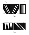
- FIGS. 4a to 4d show exemplary embodiments of the respectively optimized for determining either lateral or vertical displacements mask elements 17,18. In each case an attachment of the sensor row is provided parallel to the x-direction 20.
- the first and second mask elements 17, 18 are realized on a common mask 12 that can be illuminated by a radiation source.
- the first mask element 17 has a pattern of two mutually parallel, obliquely aligned to the x-direction 20 lines and thus in a certain Form a V-shape, whereas the second mask member 18 has four parallel to each other, arranged perpendicular to the x-direction 20 lines.
- the first and second partial projections are thus generated by this mask 12 intertwined. It shows FIG. 5 As can be seen, arise by the projection 50 eight points of light on the sensor line 11, wherein the two left outer and the two right outer points of light through the first Partial projection 51 and the inner four points of light caused by the second partial projection 52.
- the extent of this displacement can be determined unambiguously and with displacements in other directions unmistakably at the respective distances of the four light points of the second mask element generated by the parallel lines.
- the second mask element is thus optimized for determining the z-shift.
- a displacement of the mask in the x-direction 20 causes a displacement of the projection 50 along the sensor line 11, which can be determined, for example, unambiguously from the position of a distance midpoint of the distance from the extreme left to the extreme right light point.
- the determination of the y-displacement can, for example, be unambiguous and unmistakable on the basis of a defined ratio of the distance from the extreme left to the extreme right light point to the distance between the two external left light points.
- FIG. 4b is another example of a first and a second mask element 17,18, which are now realized side by side on a common mask 12 is illustrated.
- the first mask element 17 has four triangles arranged next to one another and thus again in a certain way a V-shape.
- the position of the center of the intensity of the illumination zones on the sensor line resulting from the triangles can thereby be unambiguous for determining the x-displacement and the ratio of the width of the illumination zones to the distance of the illumination zones can be used for unambiguous determination independent of shifts in the x and z directions the y-shift can be used.
- the first mask element 17 is thus optimized for the determination of lateral displacements.
- the second mask element 18 is according to the embodiment in FIG. 4a trained and thus designed for the determination of z-displacements.
- FIG. 4c are the FIG. 4a corresponding two mask elements 17,18 realized on two separate masks 13,14.
- the separate masks 13,14 can now - as in the FIGS. 2b . 6a or 6b - Illuminated by two separate sources and their partial projections either side by side, in one another or staggered time combined and mapped on the sensor line.
- FIG. 4d are the similar ones Figure 4c formed two mask elements 17,18 realized on two separate masks 13,14.
- the second mask element 18 is for attachment to a movement section, which carries out only y- and z-displacements with the probe element together, which, for example, the embodiment of FIG. 2b corresponds, provided. Since an alteration of the second partial projection produced by the second mask element 18 caused by an x-shift can therefore be ruled out from the outset, in this embodiment of the second mask element 18 a y-shift can be based on a movement of the second partial projection along the sensor line with high resolution be determined. As before, it is also possible to determine z shifts based on scaling changes of the second partial projection 18 on the sensor line.
- the second mask element 18 shown in this embodiment is thus optimized for determining the z and the y displacement.
- the first mask element 17 as already in the description to FIG. 4b is optimized for the determination of lateral displacements, an averaging of the first partial projection and based on the second partial projection determined y-shift values can be carried out and thus a y-shift can be determined more accurately.
- Figures 6a and 6b show two embodiments for juxtaposed merging the first and second partial projections produced by two separate masks 13,14.
- FIG. 6a is a to FIG. 2b alternative example shown.
- the two partial projections are now not separated in time, but brought together side by side, so that they are displayed side by side on the one sensor line.
- FIG. 6b shows an example of a merging of two generated by separate on masks 13,14 mask elements generated, side-by-side partial projections, both radiation sources 15,16 and masks 13,14 are fixedly attached to the probe element.
- FIG. 7 an exemplary embodiment is shown in which the partial projections produced by the radiation source 15 and the first and second mask elements 12 are enlarged by means of reflective elements 32 and imaged sharply on the sensor array 11 by additional lenses 33.
- the feeler element 6 embodied as a stylus can also be suspended tiltably relative to the measuring head base, so that the feeler element 6 is tilted when a measurement object is scanned.
- a first and second partial projection can now be generated on the sensor row, so that changes in the two partial projections produced on the sensor row are also read out by tilting the probe element 6 in such a way that the x-, y- and z displacement of the contacting part 5 relative to the measuring head base are determined.
- FIGS. 8a and 8b show - for a more understandable illustration once without and once with movement sections 40,41,42 of the measuring head system 1 - another embodiment for the generation of partial projections on the sensor line 11.
- This variant provides that the radiation source 15 light in the negative z- Direction 22 on a parabolic mirror 35 emits. This is fixed to the probe element 6 and thus performs all Tastelementausschungen with.
- the mask 12 according to the invention with two different mask elements and an enlarging optics 34. The light beam is now on reflected the mirror surface of the paraboloid 35 and deflected to the side.
- a cylindrical hollow mirror 36 is arranged outside the movement sections 40, 41, 42, so that the partial projections are imaged on the sensor line 11.
- the radiation source 15, the magnifying optic 34, the mask 12 and the cylindrical hollow mirror 36 are fixedly attached to the measuring head base. Only the parabolic mirror 35 is arranged on the probe element 6 for co-execution of its movements or of the movements of the contacting part 5 of the probe element 6.
- the movement sections are at least half transparent, so that the beam path of the partial projections is not interrupted or adversely affected by the movement sections 40,41,42.
Priority Applications (9)
| Application Number | Priority Date | Filing Date | Title |
|---|---|---|---|
| EP07119973A EP2056063A1 (fr) | 2007-11-05 | 2007-11-05 | Système de tête de mesure pour une machine de mesure de coordonnées et procédé de mesure optique de déplacements d'un élément palpeur du système de tête de mesure |
| US12/741,075 US8294906B2 (en) | 2007-11-05 | 2008-10-29 | Measuring head system for a coordinate measuring machine and method for optically measuring of displacements of a probe element |
| PCT/EP2008/064642 WO2009059916A1 (fr) | 2007-11-05 | 2008-10-29 | Système de tête de mesure pour une machine de mesure de coordonnées et procédé de mesure optique de déplacements d'une sonde du système de tête de mesure |
| EP08846763A EP2208015B1 (fr) | 2007-11-05 | 2008-10-29 | Système de tête de mesure pour une machine de mesure de coordonnées et procédé de mesure optique de déplacements d'une sonde du système de tête de mesure |
| DE502008002434T DE502008002434D1 (de) | 2007-11-05 | 2008-10-29 | Messkopfsystem für eine koordinatenmessmaschine und verfahren zum optischen messen von verschiebungen eines tastelements des messkopfsystems |
| CN2008801146287A CN101849159B (zh) | 2007-11-05 | 2008-10-29 | 坐标测量仪的测量头系统和测量头系统的扫描元件的位移的光学测量方法 |
| AT08846763T ATE496276T1 (de) | 2007-11-05 | 2008-10-29 | Messkopfsystem für eine koordinatenmessmaschine und verfahren zum optischen messen von verschiebungen eines tastelements des messkopfsystems |
| AU2008324308A AU2008324308B2 (en) | 2007-11-05 | 2008-10-29 | Measuring head system for a coordinate measuring machine and method for the optical measurement of displacements of a scanning element of the measuring head system |
| CA2702823A CA2702823C (fr) | 2007-11-05 | 2008-10-29 | Systeme de tete de mesure pour une machine de mesure de coordonnees et procede de mesure optique de deplacements d'une sonde du systeme de tete de mesure |
Applications Claiming Priority (1)
| Application Number | Priority Date | Filing Date | Title |
|---|---|---|---|
| EP07119973A EP2056063A1 (fr) | 2007-11-05 | 2007-11-05 | Système de tête de mesure pour une machine de mesure de coordonnées et procédé de mesure optique de déplacements d'un élément palpeur du système de tête de mesure |
Publications (1)
| Publication Number | Publication Date |
|---|---|
| EP2056063A1 true EP2056063A1 (fr) | 2009-05-06 |
Family
ID=39739386
Family Applications (2)
| Application Number | Title | Priority Date | Filing Date |
|---|---|---|---|
| EP07119973A Withdrawn EP2056063A1 (fr) | 2007-11-05 | 2007-11-05 | Système de tête de mesure pour une machine de mesure de coordonnées et procédé de mesure optique de déplacements d'un élément palpeur du système de tête de mesure |
| EP08846763A Active EP2208015B1 (fr) | 2007-11-05 | 2008-10-29 | Système de tête de mesure pour une machine de mesure de coordonnées et procédé de mesure optique de déplacements d'une sonde du système de tête de mesure |
Family Applications After (1)
| Application Number | Title | Priority Date | Filing Date |
|---|---|---|---|
| EP08846763A Active EP2208015B1 (fr) | 2007-11-05 | 2008-10-29 | Système de tête de mesure pour une machine de mesure de coordonnées et procédé de mesure optique de déplacements d'une sonde du système de tête de mesure |
Country Status (8)
| Country | Link |
|---|---|
| US (1) | US8294906B2 (fr) |
| EP (2) | EP2056063A1 (fr) |
| CN (1) | CN101849159B (fr) |
| AT (1) | ATE496276T1 (fr) |
| AU (1) | AU2008324308B2 (fr) |
| CA (1) | CA2702823C (fr) |
| DE (1) | DE502008002434D1 (fr) |
| WO (1) | WO2009059916A1 (fr) |
Cited By (1)
| Publication number | Priority date | Publication date | Assignee | Title |
|---|---|---|---|---|
| DE102009030929A1 (de) * | 2009-06-25 | 2010-12-30 | Carl Zeiss Ag | Tastkopf für ein Koordinatenmessgerät |
Families Citing this family (36)
| Publication number | Priority date | Publication date | Assignee | Title |
|---|---|---|---|---|
| US9551575B2 (en) | 2009-03-25 | 2017-01-24 | Faro Technologies, Inc. | Laser scanner having a multi-color light source and real-time color receiver |
| DE102009015920B4 (de) | 2009-03-25 | 2014-11-20 | Faro Technologies, Inc. | Vorrichtung zum optischen Abtasten und Vermessen einer Umgebung |
| US9210288B2 (en) | 2009-11-20 | 2015-12-08 | Faro Technologies, Inc. | Three-dimensional scanner with dichroic beam splitters to capture a variety of signals |
| US9529083B2 (en) | 2009-11-20 | 2016-12-27 | Faro Technologies, Inc. | Three-dimensional scanner with enhanced spectroscopic energy detector |
| DE102009057101A1 (de) | 2009-11-20 | 2011-05-26 | Faro Technologies, Inc., Lake Mary | Vorrichtung zum optischen Abtasten und Vermessen einer Umgebung |
| US9113023B2 (en) | 2009-11-20 | 2015-08-18 | Faro Technologies, Inc. | Three-dimensional scanner with spectroscopic energy detector |
| US8630314B2 (en) | 2010-01-11 | 2014-01-14 | Faro Technologies, Inc. | Method and apparatus for synchronizing measurements taken by multiple metrology devices |
| US9163922B2 (en) | 2010-01-20 | 2015-10-20 | Faro Technologies, Inc. | Coordinate measurement machine with distance meter and camera to determine dimensions within camera images |
| US8284407B2 (en) | 2010-01-20 | 2012-10-09 | Faro Technologies, Inc. | Coordinate measuring machine having an illuminated probe end and method of operation |
| US8832954B2 (en) | 2010-01-20 | 2014-09-16 | Faro Technologies, Inc. | Coordinate measurement machines with removable accessories |
| US8875409B2 (en) | 2010-01-20 | 2014-11-04 | Faro Technologies, Inc. | Coordinate measurement machines with removable accessories |
| US8677643B2 (en) | 2010-01-20 | 2014-03-25 | Faro Technologies, Inc. | Coordinate measurement machines with removable accessories |
| US8615893B2 (en) | 2010-01-20 | 2013-12-31 | Faro Technologies, Inc. | Portable articulated arm coordinate measuring machine having integrated software controls |
| JP5192614B1 (ja) | 2010-01-20 | 2013-05-08 | ファロ テクノロジーズ インコーポレーテッド | 座標測定デバイス |
| US9628775B2 (en) | 2010-01-20 | 2017-04-18 | Faro Technologies, Inc. | Articulated arm coordinate measurement machine having a 2D camera and method of obtaining 3D representations |
| GB2490631B (en) | 2010-01-20 | 2016-11-02 | Faro Tech Inc | Portable articulated arm coordinate measuring machine with multi-bus arm technology |
| US9607239B2 (en) | 2010-01-20 | 2017-03-28 | Faro Technologies, Inc. | Articulated arm coordinate measurement machine having a 2D camera and method of obtaining 3D representations |
| US9879976B2 (en) | 2010-01-20 | 2018-01-30 | Faro Technologies, Inc. | Articulated arm coordinate measurement machine that uses a 2D camera to determine 3D coordinates of smoothly continuous edge features |
| US8898919B2 (en) | 2010-01-20 | 2014-12-02 | Faro Technologies, Inc. | Coordinate measurement machine with distance meter used to establish frame of reference |
| DE102010020925B4 (de) | 2010-05-10 | 2014-02-27 | Faro Technologies, Inc. | Verfahren zum optischen Abtasten und Vermessen einer Umgebung |
| DE112011102995B4 (de) | 2010-09-08 | 2016-05-19 | Faro Technologies Inc. | Laserscanner oder Lasernachführungsgerät mit einem Projektor |
| US9168654B2 (en) | 2010-11-16 | 2015-10-27 | Faro Technologies, Inc. | Coordinate measuring machines with dual layer arm |
| WO2013097671A1 (fr) * | 2011-12-30 | 2013-07-04 | 国民技术股份有限公司 | Procédé de communication et système de communication |
| JP5936357B2 (ja) * | 2012-01-06 | 2016-06-22 | 株式会社ミツトヨ | 姿勢検出器、接触プローブ、および、マルチセンシングプローブ |
| DE102012100609A1 (de) | 2012-01-25 | 2013-07-25 | Faro Technologies, Inc. | Vorrichtung zum optischen Abtasten und Vermessen einer Umgebung |
| EP2629048B1 (fr) * | 2012-02-20 | 2018-10-24 | Tesa Sa | Palpeur |
| US8997362B2 (en) | 2012-07-17 | 2015-04-07 | Faro Technologies, Inc. | Portable articulated arm coordinate measuring machine with optical communications bus |
| DE102012109481A1 (de) | 2012-10-05 | 2014-04-10 | Faro Technologies, Inc. | Vorrichtung zum optischen Abtasten und Vermessen einer Umgebung |
| US9513107B2 (en) | 2012-10-05 | 2016-12-06 | Faro Technologies, Inc. | Registration calculation between three-dimensional (3D) scans based on two-dimensional (2D) scan data from a 3D scanner |
| US10067231B2 (en) | 2012-10-05 | 2018-09-04 | Faro Technologies, Inc. | Registration calculation of three-dimensional scanner data performed between scans based on measurements by two-dimensional scanner |
| DE102013102476B4 (de) * | 2013-03-12 | 2023-09-14 | Carl Mahr Holding Gmbh | Tasteinheit |
| US10869175B2 (en) | 2014-11-04 | 2020-12-15 | Nathan Schumacher | System and method for generating a three-dimensional model using flowable probes |
| US11073382B2 (en) * | 2015-11-13 | 2021-07-27 | Hexagon Technology Center Gmbh | Error compensation for coordinate measuring machines using a reference module |
| DE102015122844A1 (de) | 2015-12-27 | 2017-06-29 | Faro Technologies, Inc. | 3D-Messvorrichtung mit Batteriepack |
| WO2018153921A1 (fr) * | 2017-02-24 | 2018-08-30 | Marposs Societa' Per Azioni | Tête de mesure bidirectionnelle permettant la vérification dimensionnelle et/ou géométrique d'une pièce mécanique |
| DE102019110389B4 (de) * | 2019-04-18 | 2021-08-12 | Carl Zeiss Industrielle Messtechnik Gmbh | Verfahren und vorrichtung zur justierung einer optischen messeinrichtung mit einem koordinatenmessgerät sowie messkopf hierfür |
Citations (6)
| Publication number | Priority date | Publication date | Assignee | Title |
|---|---|---|---|---|
| DD125296A1 (fr) * | 1976-01-29 | 1977-04-13 | ||
| DE2741413A1 (de) * | 1976-09-27 | 1978-03-30 | Sgtc Soc General Int | Zweiachsige fuehlervorrichtung zur steuerung von einrichtungen zum kopieren von schablonen fuer werkzeugmaschinen |
| GB2150282A (en) * | 1983-11-25 | 1985-06-26 | Sigma Ltd | Measurement apparatus |
| US5048194A (en) * | 1987-12-05 | 1991-09-17 | Renishaw Plc | Position sensing probe |
| DE4409360A1 (de) * | 1993-03-19 | 1994-09-22 | Renishaw Plc | Analogsonde |
| WO2005085749A1 (fr) * | 2004-02-26 | 2005-09-15 | Carl Zeiss Industrielle Messtechnik Gmbh | Sonde pour un appareil de mesure de coordonnees |
Family Cites Families (3)
| Publication number | Priority date | Publication date | Assignee | Title |
|---|---|---|---|---|
| DE3826581A1 (de) | 1988-08-04 | 1990-02-08 | Freund H Mora Messgeraete | Elektronischer koordinatenmesstaster |
| JPH0789045B2 (ja) | 1988-12-15 | 1995-09-27 | 富山県 | 三次元変位量測定器 |
| DE19514815C2 (de) * | 1995-04-21 | 1997-02-13 | Gerlach Dieter | Meßeinrichtung mit einem auf einer Führungseinheit entlang eines Maßstabs verfahrbaren Meßkopf und mit einem Taster |
-
2007
- 2007-11-05 EP EP07119973A patent/EP2056063A1/fr not_active Withdrawn
-
2008
- 2008-10-29 EP EP08846763A patent/EP2208015B1/fr active Active
- 2008-10-29 AT AT08846763T patent/ATE496276T1/de active
- 2008-10-29 AU AU2008324308A patent/AU2008324308B2/en not_active Ceased
- 2008-10-29 CA CA2702823A patent/CA2702823C/fr not_active Expired - Fee Related
- 2008-10-29 WO PCT/EP2008/064642 patent/WO2009059916A1/fr active Application Filing
- 2008-10-29 CN CN2008801146287A patent/CN101849159B/zh not_active Expired - Fee Related
- 2008-10-29 US US12/741,075 patent/US8294906B2/en active Active
- 2008-10-29 DE DE502008002434T patent/DE502008002434D1/de active Active
Patent Citations (6)
| Publication number | Priority date | Publication date | Assignee | Title |
|---|---|---|---|---|
| DD125296A1 (fr) * | 1976-01-29 | 1977-04-13 | ||
| DE2741413A1 (de) * | 1976-09-27 | 1978-03-30 | Sgtc Soc General Int | Zweiachsige fuehlervorrichtung zur steuerung von einrichtungen zum kopieren von schablonen fuer werkzeugmaschinen |
| GB2150282A (en) * | 1983-11-25 | 1985-06-26 | Sigma Ltd | Measurement apparatus |
| US5048194A (en) * | 1987-12-05 | 1991-09-17 | Renishaw Plc | Position sensing probe |
| DE4409360A1 (de) * | 1993-03-19 | 1994-09-22 | Renishaw Plc | Analogsonde |
| WO2005085749A1 (fr) * | 2004-02-26 | 2005-09-15 | Carl Zeiss Industrielle Messtechnik Gmbh | Sonde pour un appareil de mesure de coordonnees |
Cited By (2)
| Publication number | Priority date | Publication date | Assignee | Title |
|---|---|---|---|---|
| DE102009030929A1 (de) * | 2009-06-25 | 2010-12-30 | Carl Zeiss Ag | Tastkopf für ein Koordinatenmessgerät |
| DE102009030929B4 (de) * | 2009-06-25 | 2016-07-28 | Carl Zeiss Ag | Tastkopf für ein Koordinatenmessgerät |
Also Published As
| Publication number | Publication date |
|---|---|
| WO2009059916A1 (fr) | 2009-05-14 |
| ATE496276T1 (de) | 2011-02-15 |
| EP2208015B1 (fr) | 2011-01-19 |
| AU2008324308A1 (en) | 2009-05-14 |
| EP2208015A1 (fr) | 2010-07-21 |
| CA2702823A1 (fr) | 2009-05-14 |
| CN101849159B (zh) | 2013-06-12 |
| DE502008002434D1 (de) | 2011-03-03 |
| US8294906B2 (en) | 2012-10-23 |
| AU2008324308B2 (en) | 2011-03-24 |
| CN101849159A (zh) | 2010-09-29 |
| US20110013199A1 (en) | 2011-01-20 |
| CA2702823C (fr) | 2013-01-08 |
Similar Documents
| Publication | Publication Date | Title |
|---|---|---|
| EP2208015B1 (fr) | Système de tête de mesure pour une machine de mesure de coordonnées et procédé de mesure optique de déplacements d'une sonde du système de tête de mesure | |
| EP1071922B1 (fr) | Procede et dispositif permettant de detecter la geometrie d'objets a l'aide d'appareils de mesure de coordonnees | |
| EP2150780B1 (fr) | Procédé et dispositif optoélectronique de mesure de position | |
| EP2450673B1 (fr) | Dispositif optique de mesure de la position | |
| DE102008060621B3 (de) | Optische Anordnung zum berührungslosen Messen oder Prüfen einer Körperoberfläche | |
| DE102005040772B4 (de) | Optischer Längen- und Geschwindigkeitssensor | |
| EP2449338B1 (fr) | Procédé et dispositif destinés à la détermination sans contact de l'épaisseur d'une bande de matériau avec correction du défaut d'alignement | |
| EP1718925B1 (fr) | Sonde pour un appareil de mesure de coordonnees | |
| EP0159354B1 (fr) | Procede et installation de mesure pluridimensionnelle d'un objet | |
| EP2381222A1 (fr) | Système de guidage doté de corpsen déplacement relatif et dispositif de détermination d'une position à l'aide du balayage optique d'une échelle de mesure. | |
| DE102009030929B4 (de) | Tastkopf für ein Koordinatenmessgerät | |
| DE112005000934B4 (de) | Koordinatenmessgerät sowie Verfahren zum Messen von Strukturen mittels eines Koordinatenmessgerätes | |
| DE102019209902A1 (de) | Optischer winkelsensor | |
| DE102014215633A1 (de) | Positionsmesseinrichtung | |
| DE102016013550B3 (de) | Profilmesssystem für eine Rauheits- und Konturmessung an einer Oberfläche eines Werkstücks | |
| DE102020124704B4 (de) | Vorrichtung und Verfahren zur Erfassung einer räumlichen Position eines Körpers | |
| EP4174447B1 (fr) | Dispositif optique de mesure de position et procédé de fonctionnement d'un dispositif optique de mesure de position | |
| DE10043828B4 (de) | Abtasteinheit für eine optische Positionsmesseinrichtung | |
| EP1872085B1 (fr) | Procede pour mesurer des structures d'un objet | |
| EP0387521A2 (fr) | Capteur optique de distances | |
| DE102022200195A1 (de) | Optische Positionsmesseinrichtung | |
| WO2015169329A1 (fr) | Appareil de mesure de coordonnées pour déterminer les propriétés géométriques d'un objet de mesure | |
| DE102008043540A1 (de) | Optische Positionsmesseinrichtung | |
| DE102005019158A1 (de) | Punktmessende optische Sensoren | |
| DE102014010417A1 (de) | Positionsmesssystem für den Nanometerbereich |
Legal Events
| Date | Code | Title | Description |
|---|---|---|---|
| PUAI | Public reference made under article 153(3) epc to a published international application that has entered the european phase |
Free format text: ORIGINAL CODE: 0009012 |
|
| AK | Designated contracting states |
Kind code of ref document: A1 Designated state(s): AT BE BG CH CY CZ DE DK EE ES FI FR GB GR HU IE IS IT LI LT LU LV MC MT NL PL PT RO SE SI SK TR |
|
| AX | Request for extension of the european patent |
Extension state: AL BA HR MK RS |
|
| AKX | Designation fees paid | ||
| REG | Reference to a national code |
Ref country code: DE Ref legal event code: 8566 |
|
| STAA | Information on the status of an ep patent application or granted ep patent |
Free format text: STATUS: THE APPLICATION IS DEEMED TO BE WITHDRAWN |
|
| 18D | Application deemed to be withdrawn |
Effective date: 20091107 |