EP2055531A1 - Tunnelkonsole für den Passagierraum eines Fahrzeugs - Google Patents
Tunnelkonsole für den Passagierraum eines Fahrzeugs Download PDFInfo
- Publication number
- EP2055531A1 EP2055531A1 EP07425689A EP07425689A EP2055531A1 EP 2055531 A1 EP2055531 A1 EP 2055531A1 EP 07425689 A EP07425689 A EP 07425689A EP 07425689 A EP07425689 A EP 07425689A EP 2055531 A1 EP2055531 A1 EP 2055531A1
- Authority
- EP
- European Patent Office
- Prior art keywords
- console according
- compartment
- wall
- inner compartment
- console
- Prior art date
- Legal status (The legal status is an assumption and is not a legal conclusion. Google has not performed a legal analysis and makes no representation as to the accuracy of the status listed.)
- Granted
Links
Images


Classifications
-
- B—PERFORMING OPERATIONS; TRANSPORTING
- B60—VEHICLES IN GENERAL
- B60R—VEHICLES, VEHICLE FITTINGS, OR VEHICLE PARTS, NOT OTHERWISE PROVIDED FOR
- B60R7/00—Stowing or holding appliances inside vehicle primarily intended for personal property smaller than suit-cases, e.g. travelling articles, or maps
- B60R7/04—Stowing or holding appliances inside vehicle primarily intended for personal property smaller than suit-cases, e.g. travelling articles, or maps in driver or passenger space, e.g. using racks
-
- B—PERFORMING OPERATIONS; TRANSPORTING
- B60—VEHICLES IN GENERAL
- B60N—SEATS SPECIALLY ADAPTED FOR VEHICLES; VEHICLE PASSENGER ACCOMMODATION NOT OTHERWISE PROVIDED FOR
- B60N3/00—Arrangements or adaptations of other passenger fittings, not otherwise provided for
- B60N3/10—Arrangements or adaptations of other passenger fittings, not otherwise provided for of receptacles for food or beverages, e.g. refrigerated
- B60N3/102—Arrangements or adaptations of other passenger fittings, not otherwise provided for of receptacles for food or beverages, e.g. refrigerated storable or foldable in a non-use position
Definitions
- the present invention concerns a tunnel console for the passenger compartment of a vehicle.
- the front seats of vehicles are positioned on opposite sides of the so-called tunnel, upon which a console having glove compartments, armrests, ashtrays, holders for mobile phone, etc., is mounted.
- the object of the present invention is that of embodying a tunnel console for the passenger compartment of a vehicle, which allows the above-indicated need to be met in a simple and economic manner.
- a tunnel console for the passenger compartment of a vehicle comprising:
- said outer compartment has a base surface defined by said hatch, when said hatch is located in the closed position.
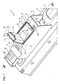
- reference numeral 1 indicates a console placed on a tunnel 2 (partially shown) in the passenger compartment of a vehicle.
- the tunnel console 1 extends along the longitudinal direction 3 of vehicle travel and is positioned between two front seats (not shown) of the passenger compartment and behind a portion of the tunnel 4 defining a support and, possibly, a pass-through opening for a lever device (not shown) that operates the hand brake of the vehicle.
- a lever device not shown
- the tunnel console 1 comprises an outer structure 5 (shown in a simplified manner) that, in turn, comprises a front portion 6 facing towards the portion of the tunnel 4 and a rear portion 7 facing towards the rear seats (not shown) of the passenger compartment.
- Portion 6 has an substantially flat upper surface 8, defining a substantially horizontal upper rest, and houses a container 9, which is connected in a fixed position with respect to the structure 5, in a known manner and not described in detail, and which internally defines a glove compartment 10.
- the compartment 10 has a top-access opening 11, which is opened/closed by lifting/lowering a hatch 12 carried by the structure 5.
- the hatch 12 comprises a rear portion 13 hinged to the structure 5 or the container 9, in a manner not shown in detail, to turn around an axis 14, horizontal and orthogonal to direction 3, between an open position ( Figure 1 ) and a closed position ( Figure 2 ), in which an upper surface 16 of the hatch 12 is positioned substantially flush with surface 8.
- the hatch 12 comprises a front appendage or recess 17, which is shaped to engage with the user's finger and facilitate the rearward lifting of the hatch 12 to the open position.
- the hatch 12 defines a lower seat 18 having a front entrance 19 ( Figure 1 ), which allows an object to be inserted/extracted in a direction 21 orthogonal to axis 14 when the hatch 12 is in the open position. Instead, when the hatch 12 is in the closed position, the entrance 19 is closed by an upper portion 23 of the container 9.
- the tunnel console 1 also comprises a wall 24, which is coupled to portion 6 or the container 9 such that it is movable between a lowered position and a raised position. In the raised position, the wall 24 projects upwards with respect to surface 8 and defines, at the sides, back and front, a compartment 25, which is permanently open at the top. The wall 24 is positioned around hatch 12, such that the bottom of the compartment 25 is at least partially defined by surface 16 when the hatch 12 is in the closed position.
- the wall 24 is preferably positioned flush with or beneath surface 8.
- the wall 24 is a rigid wall that has a substantially rectangular, closed, annular profile in plan and which is fitted around the container 9.
- the wall 24 engages in a sliding manner with an opening 26 defined by a slit between surface 8 and the upper edge of the container 9 and, at its bottom end, carries an appendage 27 that projects outwards with respect to the wall 24.
- a latch retaining device (indicated by reference numeral 28 in the variant in Figure 3 ) is provided to keep the wall 24 in the lowered position.
- the retaining device is released by the user pressing a release button 29.
- a spring system (not shown) pushes the wall 24 towards its raised position until it makes the appendage 27 hit against portion 6.
- a friction holding system is provided (placed, for example, along the opening 26).
- the tunnel console 1 houses an air duct 30, which constitutes part of the passenger compartment's ventilation and air distribution system, and comprises a front portion 31 connected to the remainder of this system, in a manner not shown, and a rear portion 32 that ends in a vent 33 to send air to the rear passengers.
- Portion 31 is housed in portion 6 beneath the container 9 and has a flattened cross-section in the vertical direction.
- Portion 32 has a substantially circular cross-section connected to portion 31, is housed in portion 7 behind the container 9, and is upwardly inclined in the rearward direction.
- the tunnel console 1 also comprises a glove compartment 35 defined by a drawer 36, which is carried by portion 7, behind the container 9 and portion 32, below the vent 33, and is longitudinally extractable in a rearwards direction from portion 7 to make compartment 35 accessible from the top, for the rear passengers in particular.
- Figures 3 to 8 show variants, the constituent parts of which, where possible, are indicated by the same reference numerals used in Figures 1 and 2 .
- the variant in Figure 3 differs from what shown in Figures 1 and 2 in that the vent 33 is placed in a lower position and in that compartment 35 is defined by a container 36a housed in a fixed position in portion 7 behind the container 9 and above portion 32.
- compartment 35 is accessible by opening a hatch 39.
- the hatch 39 has an upper portion hinged to portion 7 to turn around an axis 40 parallel to axis 14 from a closed position, in which it is substantially coplanar with the vent 33, upwards to an open position (not shown). In this way, the opening trajectory of the hatch 39 does not disturb the airflow leaving the vent 33.
- the variant in Figure 4 differs from what shown in Figures 1 and 2 in the position of the release button 29, which is positioned in front of the wall 24, for the fact that the wall 24 is defined by two pieces 24a and 24b coupled together in a telescopic manner in a substantially vertical direction, and due to the presence of two vents 33a and 33b at the end of the air duct 30.
- Wall 24c comprises an intermediate portion 45 positioned in front of the container 9 and having an arc-like shape, with the centre of curvature defined by axis 43, and two side portions 46 positioned at the sides of the container 9 and shaped substantially like a sector of a circle.
- the compartment 25 is delimited at the front by portion 45 and at the sides by portions 46.
- wall 24c has an upper edge 47 that slightly projects from opening 26 with respect to surface 8 and defines a grip portion that the user can grasp by hand to move wall 24c to the raised position.
- portion 45 is longitudinally spaced apart from the container 9 along surface 8.
- the space between portion 45 and the container 9 along surface 8 is preferable covered by a front portion 48 of the hatch 12.
- FIG. 7 and 8 differs from what shown in Figures 5 and 6 due to presence of two vertical seats 50, open at the top for respectively putting away objects and positioned on opposite sides of portion 32 of the air duct 30, and because compartment 35 is defined by a container 36b, which is housed in a fixed position in portion 7 behind and below portion 32 of the air duct 30.
- a rear hatch 39a has one side hinged to portion 7 or to container 36b, to turn around an axis 40a parallel to axis 14 from a first position, in which it closes compartment 35 and is substantially coplanar with the vent 33, downwards to a second position ( Figure 8 ), in which it leaves compartment 35 open.
- the opening trajectory of the hatch 39a does not disturb the airflow leaving the vent 33.
- the hatch 39a is substantially horizontal to define a support and, on its upward-facing side, defines a seat 51 that can be used to accommodate and support the bottom of an object, such as a can for example.
- the wall 24,24c allows an outer glove compartment 25 to be obtained in a simple manner in case of need, without creating significant additional occupied space with respect to that occupied by the other components of the tunnel console 1.
- the wall 24,24c provides both versatility of use and a certain aesthetic quality to the tunnel console 1.
- the wall 24 could also be used as an armrest for the front seats, which are positioned at the side of the tunnel console.
- the tunnel console 1 is also useful for rear passengers, not only thanks to the air duct 30, but also to compartment 35, which is placed in a position such as to keep the dimensions of portion 7 of the tunnel console 1 compact.
- hatch 39a allows access to both seat 51 and compartment 34 at the same time.
- the air duct 30 has characteristics that render the tunnel console 1 extremely compact.
- the rotating wall 24c or sliding wall 24 could be defined by a folding element that assumes an upright position when raised with respect to portion 6 of the structure 5 and is concertina-folded for lowering against surface 8 or into a seat flush with surface 8.
Landscapes
- Engineering & Computer Science (AREA)
- Mechanical Engineering (AREA)
- Physics & Mathematics (AREA)
- Thermal Sciences (AREA)
- Transportation (AREA)
- Vehicle Step Arrangements And Article Storage (AREA)
- Body Structure For Vehicles (AREA)
Priority Applications (4)
| Application Number | Priority Date | Filing Date | Title |
|---|---|---|---|
| EP07425689A EP2055531B1 (de) | 2007-10-31 | 2007-10-31 | Tunnelkonsole für den Passagierraum eines Fahrzeugs |
| AT07425689T ATE471842T1 (de) | 2007-10-31 | 2007-10-31 | Tunnelkonsole für den passagierraum eines fahrzeugs |
| DE602007007341T DE602007007341D1 (de) | 2007-10-31 | 2007-10-31 | Tunnelkonsole für den Passagierraum eines Fahrzeugs |
| US12/289,421 US7802833B2 (en) | 2007-10-31 | 2008-10-28 | Tunnel console for passenger compartment of a vehicle |
Applications Claiming Priority (1)
| Application Number | Priority Date | Filing Date | Title |
|---|---|---|---|
| EP07425689A EP2055531B1 (de) | 2007-10-31 | 2007-10-31 | Tunnelkonsole für den Passagierraum eines Fahrzeugs |
Publications (2)
| Publication Number | Publication Date |
|---|---|
| EP2055531A1 true EP2055531A1 (de) | 2009-05-06 |
| EP2055531B1 EP2055531B1 (de) | 2010-06-23 |
Family
ID=39259633
Family Applications (1)
| Application Number | Title | Priority Date | Filing Date |
|---|---|---|---|
| EP07425689A Not-in-force EP2055531B1 (de) | 2007-10-31 | 2007-10-31 | Tunnelkonsole für den Passagierraum eines Fahrzeugs |
Country Status (4)
| Country | Link |
|---|---|
| US (1) | US7802833B2 (de) |
| EP (1) | EP2055531B1 (de) |
| AT (1) | ATE471842T1 (de) |
| DE (1) | DE602007007341D1 (de) |
Families Citing this family (13)
| Publication number | Priority date | Publication date | Assignee | Title |
|---|---|---|---|---|
| KR100809047B1 (ko) * | 2007-03-20 | 2008-03-03 | 류희석 | 휴대용 단말기 수납부가 구비된 대시보드 |
| DE102008019867B4 (de) * | 2008-04-16 | 2012-12-20 | Faurecia Innenraum Systeme Gmbh | Staufach |
| US8382183B2 (en) * | 2008-04-25 | 2013-02-26 | Faurecia Interior Systems, Inc. | Spine member and accessory module apparatus |
| US8196985B2 (en) * | 2009-12-01 | 2012-06-12 | Toyota Motor Engineering & Manufacturing North America, Inc. | Console assembly |
| DE102010047626A1 (de) * | 2010-10-06 | 2012-04-12 | Gm Global Technology Operations Llc (N.D.Ges.D. Staates Delaware) | Kraftfahrzeug |
| DE102012018777A1 (de) * | 2012-09-24 | 2014-04-17 | GM Global Technology Operations LLC (n. d. Ges. d. Staates Delaware) | Mittelkonsolenelement für ein Kraftfahrzeug |
| JP6020352B2 (ja) * | 2013-05-28 | 2016-11-02 | 豊田合成株式会社 | ダクト装置 |
| JP5797721B2 (ja) * | 2013-10-25 | 2015-10-21 | 本田技研工業株式会社 | 車両用空調装置 |
| US9321402B2 (en) * | 2014-01-22 | 2016-04-26 | Ford Global Technologies, Llc | Multi-function automotive trunk storage drawer |
| US9156407B1 (en) | 2014-09-17 | 2015-10-13 | Honda Motor Co., Ltd. | Vehicular storage assembly and methods of use and manufacture thereof |
| DE102015214220B4 (de) * | 2015-07-28 | 2023-09-07 | Volkswagen Aktiengesellschaft | Ablagesystem für ein Fahrzeug |
| CN105946729B (zh) * | 2016-06-12 | 2018-07-03 | 浙江吉利控股集团有限公司 | 车用扶手箱结构和汽车 |
| EP3524477B1 (de) * | 2018-02-13 | 2020-10-21 | Volvo Car Corporation | Fahrzeugloungekonsole |
Citations (5)
| Publication number | Priority date | Publication date | Assignee | Title |
|---|---|---|---|---|
| EP0189051A2 (de) | 1985-01-19 | 1986-07-30 | Iveco Magirus Aktiengesellschaft | Ablageanordnung für Kraftfahrzeuge, insbesondere im Tunnelbereich von Lastkraftwagen |
| EP0219632A1 (de) | 1985-09-25 | 1987-04-29 | MAN Nutzfahrzeuge Aktiengesellschaft | Ablagekasten mit Stauraum |
| US5562331A (en) * | 1994-12-09 | 1996-10-08 | Prince Corporation | Storage compartment with cover |
| DE19542198A1 (de) * | 1995-11-13 | 1997-05-15 | Daimler Benz Ag | Armauflage für eine Mittelkonsole eines Kraftfahrzeugs |
| DE19826943A1 (de) * | 1998-06-17 | 1999-12-23 | Daimler Chrysler Ag | Tunnelverkleidung für ein Kraftfahrzeug |
Family Cites Families (4)
| Publication number | Priority date | Publication date | Assignee | Title |
|---|---|---|---|---|
| JPH09328039A (ja) | 1996-06-10 | 1997-12-22 | Kanto Auto Works Ltd | 自動車用ラック |
| US5902181A (en) * | 1998-05-01 | 1999-05-11 | Chrysler Corporation | Diverter valve assembly for an automobile HVAC system |
| JP2008529882A (ja) * | 2005-02-09 | 2008-08-07 | ジョンソン コントロールズ テクノロジー カンパニー | コンソール収納囲壁部 |
| JP4488946B2 (ja) * | 2005-04-04 | 2010-06-23 | 株式会社ニフコ | カップホルダー |
-
2007
- 2007-10-31 DE DE602007007341T patent/DE602007007341D1/de active Active
- 2007-10-31 EP EP07425689A patent/EP2055531B1/de not_active Not-in-force
- 2007-10-31 AT AT07425689T patent/ATE471842T1/de not_active IP Right Cessation
-
2008
- 2008-10-28 US US12/289,421 patent/US7802833B2/en not_active Expired - Fee Related
Patent Citations (5)
| Publication number | Priority date | Publication date | Assignee | Title |
|---|---|---|---|---|
| EP0189051A2 (de) | 1985-01-19 | 1986-07-30 | Iveco Magirus Aktiengesellschaft | Ablageanordnung für Kraftfahrzeuge, insbesondere im Tunnelbereich von Lastkraftwagen |
| EP0219632A1 (de) | 1985-09-25 | 1987-04-29 | MAN Nutzfahrzeuge Aktiengesellschaft | Ablagekasten mit Stauraum |
| US5562331A (en) * | 1994-12-09 | 1996-10-08 | Prince Corporation | Storage compartment with cover |
| DE19542198A1 (de) * | 1995-11-13 | 1997-05-15 | Daimler Benz Ag | Armauflage für eine Mittelkonsole eines Kraftfahrzeugs |
| DE19826943A1 (de) * | 1998-06-17 | 1999-12-23 | Daimler Chrysler Ag | Tunnelverkleidung für ein Kraftfahrzeug |
Also Published As
| Publication number | Publication date |
|---|---|
| DE602007007341D1 (de) | 2010-08-05 |
| US7802833B2 (en) | 2010-09-28 |
| US20090134649A1 (en) | 2009-05-28 |
| EP2055531B1 (de) | 2010-06-23 |
| ATE471842T1 (de) | 2010-07-15 |
Similar Documents
| Publication | Publication Date | Title |
|---|---|---|
| US7802833B2 (en) | Tunnel console for passenger compartment of a vehicle | |
| US7784843B2 (en) | Vehicle console with sliding panel | |
| KR102563594B1 (ko) | 컵홀더를 갖는 콘솔 | |
| JP4204312B2 (ja) | センタコンソールアセンブリ | |
| US7237816B1 (en) | Automotive center console with open front face | |
| JP3764095B2 (ja) | 車両のセンターコンソール | |
| US9840172B2 (en) | Multipurpose armrest for vehicle | |
| US5505516A (en) | Compact container holder | |
| US6045173A (en) | Console with multi-position cover | |
| US8196985B2 (en) | Console assembly | |
| US6921118B2 (en) | Sliding and nesting console system | |
| US8777173B2 (en) | Holding apparatus | |
| US8052190B2 (en) | Multi-position cargo holder for use in vehicles | |
| US8708408B2 (en) | Armrest assembly having beverage holder | |
| CN204915498U (zh) | 用于车辆的车门 | |
| US8991891B2 (en) | Device for covering a storage compartment and storage compartment device | |
| CN108263291B (zh) | 车门 | |
| JP2015510853A (ja) | 車両の収納コンパートメントアセンブリ | |
| JP2008279891A (ja) | コンソールボックス | |
| US5803326A (en) | Tour guide cabinet for use in a passenger vehicle | |
| JP3770129B2 (ja) | 車両用収納ボックス | |
| EP2465377A1 (de) | Fahrzeugtisch und entsprechendes Gehäuse im Fahrzeugarmaturenbrett, insbesondere für Industrie- oder Nutzfahrzeuge | |
| JP5158773B2 (ja) | コンソールボックス | |
| JP2016055829A (ja) | 自動車のセンターコンソール構造 | |
| KR20120032074A (ko) | 자동차의 센터콘솔 암레스트 조립체 |
Legal Events
| Date | Code | Title | Description |
|---|---|---|---|
| PUAI | Public reference made under article 153(3) epc to a published international application that has entered the european phase |
Free format text: ORIGINAL CODE: 0009012 |
|
| 17P | Request for examination filed |
Effective date: 20080701 |
|
| AK | Designated contracting states |
Kind code of ref document: A1 Designated state(s): AT BE BG CH CY CZ DE DK EE ES FI FR GB GR HU IE IS IT LI LT LU LV MC MT NL PL PT RO SE SI SK TR |
|
| AX | Request for extension of the european patent |
Extension state: AL BA HR MK RS |
|
| GRAP | Despatch of communication of intention to grant a patent |
Free format text: ORIGINAL CODE: EPIDOSNIGR1 |
|
| AKX | Designation fees paid |
Designated state(s): AT BE BG CH CY CZ DE DK EE ES FI FR GB GR HU IE IS IT LI LT LU LV MC MT NL PL PT RO SE SI SK TR |
|
| GRAS | Grant fee paid |
Free format text: ORIGINAL CODE: EPIDOSNIGR3 |
|
| GRAA | (expected) grant |
Free format text: ORIGINAL CODE: 0009210 |
|
| AK | Designated contracting states |
Kind code of ref document: B1 Designated state(s): AT BE BG CH CY CZ DE DK EE ES FI FR GB GR HU IE IS IT LI LT LU LV MC MT NL PL PT RO SE SI SK TR |
|
| REG | Reference to a national code |
Ref country code: CH Ref legal event code: EP |
|
| REG | Reference to a national code |
Ref country code: IE Ref legal event code: FG4D |
|
| REF | Corresponds to: |
Ref document number: 602007007341 Country of ref document: DE Date of ref document: 20100805 Kind code of ref document: P |
|
| REG | Reference to a national code |
Ref country code: NL Ref legal event code: VDEP Effective date: 20100623 |
|
| PG25 | Lapsed in a contracting state [announced via postgrant information from national office to epo] |
Ref country code: SE Free format text: LAPSE BECAUSE OF FAILURE TO SUBMIT A TRANSLATION OF THE DESCRIPTION OR TO PAY THE FEE WITHIN THE PRESCRIBED TIME-LIMIT Effective date: 20100623 Ref country code: LT Free format text: LAPSE BECAUSE OF FAILURE TO SUBMIT A TRANSLATION OF THE DESCRIPTION OR TO PAY THE FEE WITHIN THE PRESCRIBED TIME-LIMIT Effective date: 20100623 |
|
| LTIE | Lt: invalidation of european patent or patent extension |
Effective date: 20100623 |
|
| PG25 | Lapsed in a contracting state [announced via postgrant information from national office to epo] |
Ref country code: SI Free format text: LAPSE BECAUSE OF FAILURE TO SUBMIT A TRANSLATION OF THE DESCRIPTION OR TO PAY THE FEE WITHIN THE PRESCRIBED TIME-LIMIT Effective date: 20100623 Ref country code: LV Free format text: LAPSE BECAUSE OF FAILURE TO SUBMIT A TRANSLATION OF THE DESCRIPTION OR TO PAY THE FEE WITHIN THE PRESCRIBED TIME-LIMIT Effective date: 20100623 Ref country code: AT Free format text: LAPSE BECAUSE OF FAILURE TO SUBMIT A TRANSLATION OF THE DESCRIPTION OR TO PAY THE FEE WITHIN THE PRESCRIBED TIME-LIMIT Effective date: 20100623 Ref country code: FI Free format text: LAPSE BECAUSE OF FAILURE TO SUBMIT A TRANSLATION OF THE DESCRIPTION OR TO PAY THE FEE WITHIN THE PRESCRIBED TIME-LIMIT Effective date: 20100623 |
|
| PG25 | Lapsed in a contracting state [announced via postgrant information from national office to epo] |
Ref country code: PL Free format text: LAPSE BECAUSE OF FAILURE TO SUBMIT A TRANSLATION OF THE DESCRIPTION OR TO PAY THE FEE WITHIN THE PRESCRIBED TIME-LIMIT Effective date: 20100623 |
|
| PG25 | Lapsed in a contracting state [announced via postgrant information from national office to epo] |
Ref country code: NL Free format text: LAPSE BECAUSE OF FAILURE TO SUBMIT A TRANSLATION OF THE DESCRIPTION OR TO PAY THE FEE WITHIN THE PRESCRIBED TIME-LIMIT Effective date: 20100623 Ref country code: EE Free format text: LAPSE BECAUSE OF FAILURE TO SUBMIT A TRANSLATION OF THE DESCRIPTION OR TO PAY THE FEE WITHIN THE PRESCRIBED TIME-LIMIT Effective date: 20100623 |
|
| PG25 | Lapsed in a contracting state [announced via postgrant information from national office to epo] |
Ref country code: CY Free format text: LAPSE BECAUSE OF FAILURE TO SUBMIT A TRANSLATION OF THE DESCRIPTION OR TO PAY THE FEE WITHIN THE PRESCRIBED TIME-LIMIT Effective date: 20100623 Ref country code: BE Free format text: LAPSE BECAUSE OF FAILURE TO SUBMIT A TRANSLATION OF THE DESCRIPTION OR TO PAY THE FEE WITHIN THE PRESCRIBED TIME-LIMIT Effective date: 20100623 Ref country code: CZ Free format text: LAPSE BECAUSE OF FAILURE TO SUBMIT A TRANSLATION OF THE DESCRIPTION OR TO PAY THE FEE WITHIN THE PRESCRIBED TIME-LIMIT Effective date: 20100623 Ref country code: SK Free format text: LAPSE BECAUSE OF FAILURE TO SUBMIT A TRANSLATION OF THE DESCRIPTION OR TO PAY THE FEE WITHIN THE PRESCRIBED TIME-LIMIT Effective date: 20100623 Ref country code: RO Free format text: LAPSE BECAUSE OF FAILURE TO SUBMIT A TRANSLATION OF THE DESCRIPTION OR TO PAY THE FEE WITHIN THE PRESCRIBED TIME-LIMIT Effective date: 20100623 Ref country code: PT Free format text: LAPSE BECAUSE OF FAILURE TO SUBMIT A TRANSLATION OF THE DESCRIPTION OR TO PAY THE FEE WITHIN THE PRESCRIBED TIME-LIMIT Effective date: 20101025 Ref country code: IS Free format text: LAPSE BECAUSE OF FAILURE TO SUBMIT A TRANSLATION OF THE DESCRIPTION OR TO PAY THE FEE WITHIN THE PRESCRIBED TIME-LIMIT Effective date: 20101023 |
|
| PG25 | Lapsed in a contracting state [announced via postgrant information from national office to epo] |
Ref country code: DK Free format text: LAPSE BECAUSE OF FAILURE TO SUBMIT A TRANSLATION OF THE DESCRIPTION OR TO PAY THE FEE WITHIN THE PRESCRIBED TIME-LIMIT Effective date: 20100623 |
|
| PLBE | No opposition filed within time limit |
Free format text: ORIGINAL CODE: 0009261 |
|
| STAA | Information on the status of an ep patent application or granted ep patent |
Free format text: STATUS: NO OPPOSITION FILED WITHIN TIME LIMIT |
|
| PG25 | Lapsed in a contracting state [announced via postgrant information from national office to epo] |
Ref country code: MC Free format text: LAPSE BECAUSE OF NON-PAYMENT OF DUE FEES Effective date: 20101031 Ref country code: GR Free format text: LAPSE BECAUSE OF FAILURE TO SUBMIT A TRANSLATION OF THE DESCRIPTION OR TO PAY THE FEE WITHIN THE PRESCRIBED TIME-LIMIT Effective date: 20100924 |
|
| 26N | No opposition filed |
Effective date: 20110324 |
|
| REG | Reference to a national code |
Ref country code: DE Ref legal event code: R097 Ref document number: 602007007341 Country of ref document: DE Effective date: 20110323 |
|
| PG25 | Lapsed in a contracting state [announced via postgrant information from national office to epo] |
Ref country code: IE Free format text: LAPSE BECAUSE OF NON-PAYMENT OF DUE FEES Effective date: 20101031 |
|
| PG25 | Lapsed in a contracting state [announced via postgrant information from national office to epo] |
Ref country code: IT Free format text: LAPSE BECAUSE OF NON-PAYMENT OF DUE FEES Effective date: 20101031 Ref country code: MT Free format text: LAPSE BECAUSE OF FAILURE TO SUBMIT A TRANSLATION OF THE DESCRIPTION OR TO PAY THE FEE WITHIN THE PRESCRIBED TIME-LIMIT Effective date: 20100623 |
|
| REG | Reference to a national code |
Ref country code: CH Ref legal event code: PL |
|
| GBPC | Gb: european patent ceased through non-payment of renewal fee |
Effective date: 20111031 |
|
| PG25 | Lapsed in a contracting state [announced via postgrant information from national office to epo] |
Ref country code: LI Free format text: LAPSE BECAUSE OF NON-PAYMENT OF DUE FEES Effective date: 20111031 Ref country code: CH Free format text: LAPSE BECAUSE OF NON-PAYMENT OF DUE FEES Effective date: 20111031 |
|
| PG25 | Lapsed in a contracting state [announced via postgrant information from national office to epo] |
Ref country code: GB Free format text: LAPSE BECAUSE OF NON-PAYMENT OF DUE FEES Effective date: 20111031 |
|
| PG25 | Lapsed in a contracting state [announced via postgrant information from national office to epo] |
Ref country code: LU Free format text: LAPSE BECAUSE OF NON-PAYMENT OF DUE FEES Effective date: 20101031 Ref country code: BG Free format text: LAPSE BECAUSE OF FAILURE TO SUBMIT A TRANSLATION OF THE DESCRIPTION OR TO PAY THE FEE WITHIN THE PRESCRIBED TIME-LIMIT Effective date: 20100623 Ref country code: HU Free format text: LAPSE BECAUSE OF FAILURE TO SUBMIT A TRANSLATION OF THE DESCRIPTION OR TO PAY THE FEE WITHIN THE PRESCRIBED TIME-LIMIT Effective date: 20101224 |
|
| PG25 | Lapsed in a contracting state [announced via postgrant information from national office to epo] |
Ref country code: TR Free format text: LAPSE BECAUSE OF FAILURE TO SUBMIT A TRANSLATION OF THE DESCRIPTION OR TO PAY THE FEE WITHIN THE PRESCRIBED TIME-LIMIT Effective date: 20100623 |
|
| PG25 | Lapsed in a contracting state [announced via postgrant information from national office to epo] |
Ref country code: BG Free format text: LAPSE BECAUSE OF FAILURE TO SUBMIT A TRANSLATION OF THE DESCRIPTION OR TO PAY THE FEE WITHIN THE PRESCRIBED TIME-LIMIT Effective date: 20100923 |
|
| PG25 | Lapsed in a contracting state [announced via postgrant information from national office to epo] |
Ref country code: ES Free format text: LAPSE BECAUSE OF FAILURE TO SUBMIT A TRANSLATION OF THE DESCRIPTION OR TO PAY THE FEE WITHIN THE PRESCRIBED TIME-LIMIT Effective date: 20101004 |
|
| REG | Reference to a national code |
Ref country code: FR Ref legal event code: PLFP Year of fee payment: 9 |
|
| PGFP | Annual fee paid to national office [announced via postgrant information from national office to epo] |
Ref country code: FR Payment date: 20150908 Year of fee payment: 9 |
|
| PGFP | Annual fee paid to national office [announced via postgrant information from national office to epo] |
Ref country code: IT Payment date: 20151006 Year of fee payment: 9 Ref country code: DE Payment date: 20151028 Year of fee payment: 9 |
|
| REG | Reference to a national code |
Ref country code: DE Ref legal event code: R119 Ref document number: 602007007341 Country of ref document: DE |
|
| REG | Reference to a national code |
Ref country code: FR Ref legal event code: ST Effective date: 20170630 |
|
| PG25 | Lapsed in a contracting state [announced via postgrant information from national office to epo] |
Ref country code: FR Free format text: LAPSE BECAUSE OF NON-PAYMENT OF DUE FEES Effective date: 20161102 Ref country code: DE Free format text: LAPSE BECAUSE OF NON-PAYMENT OF DUE FEES Effective date: 20170503 |
|
| PG25 | Lapsed in a contracting state [announced via postgrant information from national office to epo] |
Ref country code: IT Free format text: LAPSE BECAUSE OF NON-PAYMENT OF DUE FEES Effective date: 20161031 |