EP2055004B1 - Method for determining the change of a signal, and an apparatus including a circuit arranged to implement the method - Google Patents
Method for determining the change of a signal, and an apparatus including a circuit arranged to implement the method Download PDFInfo
- Publication number
- EP2055004B1 EP2055004B1 EP07837119A EP07837119A EP2055004B1 EP 2055004 B1 EP2055004 B1 EP 2055004B1 EP 07837119 A EP07837119 A EP 07837119A EP 07837119 A EP07837119 A EP 07837119A EP 2055004 B1 EP2055004 B1 EP 2055004B1
- Authority
- EP
- European Patent Office
- Prior art keywords
- samples
- sample
- measurement window
- measurement
- window
- Prior art date
- Legal status (The legal status is an assumption and is not a legal conclusion. Google has not performed a legal analysis and makes no representation as to the accuracy of the status listed.)
- Ceased
Links
Images


Classifications
-
- G—PHYSICS
- G06—COMPUTING OR CALCULATING; COUNTING
- G06F—ELECTRIC DIGITAL DATA PROCESSING
- G06F17/00—Digital computing or data processing equipment or methods, specially adapted for specific functions
- G06F17/10—Complex mathematical operations
-
- H—ELECTRICITY
- H03—ELECTRONIC CIRCUITRY
- H03M—CODING; DECODING; CODE CONVERSION IN GENERAL
- H03M1/00—Analogue/digital conversion; Digital/analogue conversion
- H03M1/06—Continuously compensating for, or preventing, undesired influence of physical parameters
- H03M1/0617—Continuously compensating for, or preventing, undesired influence of physical parameters characterised by the use of methods or means not specific to a particular type of detrimental influence
- H03M1/0626—Continuously compensating for, or preventing, undesired influence of physical parameters characterised by the use of methods or means not specific to a particular type of detrimental influence by filtering
-
- H—ELECTRICITY
- H03—ELECTRONIC CIRCUITRY
- H03M—CODING; DECODING; CODE CONVERSION IN GENERAL
- H03M1/00—Analogue/digital conversion; Digital/analogue conversion
- H03M1/12—Analogue/digital converters
Definitions
- the present invention relates to a method of determining a change in a signal over a time period or the gradient of an over sampled signal, and to an apparatus including a circuit for determining the gradient or change of an over sampled signal.
- the slope of the integral represents an average value of a current.
- the average value is then digitised, for example by taking a sample at a first instant in time, taking a sample at a second instant in time, and subtracting the difference between the two values to obtain the difference, and hence infer a gradient during the sample period. Relying on one or two samples like this may render the measurements susceptible to noise. Whilst over sampling a signal can provide improvements in measurements of a parameter, the over sampling can give rise to a computational overhead.
- EP 1085469 discloses a CT scanner having a flat panel detector. Complementary samples, being results from rays that have a projection view 180° apart, are summed using a weighting function such that the sum of their weights equal unity.
- a method of estimating a change of an integrator output variable over a measurement window comprising the steps of:
- an apparatus for estimating a change in a measurand during a measurement window characterised by:
- the length of the measurement window may vary in time, perhaps because the measurement window represents a "view" from a computerised tomography scanner and the scan head is subject to speed changes, then it may be necessary to take account of the fact that each of the samples are not equally spaced apart in time.
- ⁇ is a further two multiplications and 1 subtraction.
- Calculation of a and b are a further two multiplies, one subtraction and a division each.
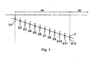
- a sample window, W 1 exists in which a plurality of samples, in this instance S 1 to S 12 . have been taken.
- Each sample has an error ⁇ such that there is a statistical probability that each sample is within ⁇ from its nominal value (typically 95% of samples satisfy this condition).
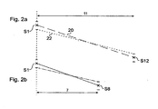
- Figure 2a compares samples S 1 and S 12 . These samples are separated by 11 units in the x axis (which may represent time or distance or amount of rotation).
- Taking multiple samples at points S 1 and S 12 may not be possible due to acquisition constraints, but taking multiple samples within the measurement window is.
- the samples need to be processed in a computationally simple way.
- the inventors have realised that acceptable estimates of the gradient can be obtained by mere addition and subtraction of the sample values - subject to the sample values being modified by a weighting function.
- the gradient calculation will be the same as calculated in Figure 2a and 2b , and is represented by solid line 30.
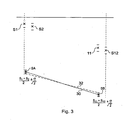
- the inventors having realised this, propose that the contribution of the various readings should be weighted, such that the contributions from some of the samples can be ignored.
- the weighting occurs in both X and Y directions such that the position of the composite sample points reflects the relative contribution of each of the samples to it.
- weighting function In high through-put digital systems it is beneficial for the weighting function to be easy to implement.
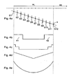
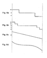
- a particularly easy weighting function to implement is shown in Figure 4b where the weighting function either has a value of 0 or a value of 1.
- the weighting function has a value of 1 for samples S 1 , S 2 , S 3 , and S 10 , S 11 , and S 12 .
- the weighting function is symmetric around the mid-point of the sampling window. This function can be implemented entirely in hardware using an adder to keep a running total of the value of the samples.
- a hardware adder can be initialised at the start of the window, and then as time progresses through the window can sum S 1 , S 2 and S 3 .
- the hardware adder then ignores samples S 4 to S 9 and is then set to a decrement mode such that as sample S 10 arrives it decrements it from the currently held sum of S 1 , S 2 and S 3 . Subsequently as sample S 11 occurs this is also decremented from the current total and finally as sample S 12 occurs this is also decremented.
- the output of the hardware summer then represents a scaled estimate of the gradient. In this example, the value in the hardware summer would represent the gradient measured effectively between S 2 and S 11 .
- the output then needs scaling, for example by a digital multiplication by a constant, to rescale the output to that which would have occurred when subtracting S 12 from S 1 .
- This value can then be passed to downstream processing circuits which had been expecting a single value corresponding to merely subtracting S 12 from S 1 .
- an improvement in the signal to noise performance has been obtained while maintaining compatibility with older data processing systems.
- the weighting function shown in Figure 4b is particularly simple to implement and also lends itself to being parameterised by a single value representing the extent of the 0 period, either in totality, or measured from the mid-point of the window.
- the function can be represented by Fn i A B where A represents the number of samples that are taken in a measurement window and B represents the number of samples that occur in a first portion 41 (which may also be regarded as a sample set) where a non-zero weight is applied. From this parameterisation the hardware or system can deduce the existence of a second portion 42 within the measurement window where a non-zero weighting is applied. As will be shown later, this parameterisation scheme can be extended.
- the parameterisation allows the weighting function to be modified rapidly if a controller determines that a different weighting/result combining function is required.
- the weighting signal can be readily regenerated using a counter to count the samples as they occur and to decide on the basis of the control parameter whether the samples are to be multiplied by 1. or to be discarded for the purposes of calculating the gradient.
- More complex gradients may also be used and that shown in Figure 4c represents a step wise function where again a central portion of the function is zero valued but where samples towards the end of the function are given different weightings.
- the function shown in Figure 4c weights samples S 1 and S 12 by twice the values of samples S 2 and S 11 . All other samples S 3 to S 10 are 0 weighted. It can be seen that the effective X position of the composite samples would occur of the way between S 1 and S 2 and of the way between S 12 and S 11 , namely with X values of and 10.67 respectively in the example shown here.
- Figure 4d shows a further variation in which a linear function, which can be replicated to the digital domain by a staircase, extends in either direction from the mid-point of the window.
- Figure 4e shows a smoothly varying function centred around the mid-point of the window.
- a generally parabolic function would be easy to implement within the digital domain as the scaling of ⁇ 2, ⁇ 4, ⁇ 8 and so on could be accomplished merely by shifting the digital word from the analog to digital converter by 1, 2, 3 and so on bits towards the least significant bit.
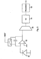
- Figure 5 schematically illustrates a measurement circuit including a processor adapted to implement the present invention.
- the measurement circuit may, for example, be a channel within a x-ray computerised tomography (CT) scanner.
- CT computerised tomography
- a CT scanner has a scintillation crystal (not shown) in association with a photo diode array.
- the photo diode array typically comprises a large number such as 64 or 128, photo diodes.
- Figure 5 schematically illustrates one such photo diode 50. In use the current from the photo diode 50 is integrated by an integrator 52 such that an estimate of the current flowing through the diode in the measurement window can be obtained.
- a reset circuit is associated with the integrator 52 and is operated at the beginning of each measurement window such that only one sample, corresponding to sample S 12 of Figure 1 need be taken at the end of each measurement window and that the value of S 12 was directly related to the current through the photo diode 50.
- noise effecting the reset voltage and the single measurement of sample S 12 gives rise to the potential to miscalculate the gradient with the measurement window.
- the output of the integrator 52 is provided to an analog to digital converter 54 by way of a multiplexer 56.
- the multiplexer allows signals from several, for example 64 or 128, photodiodes to be sent to a single analog to digital converter in time multiplexed fashion. For simplicity, we need only consider what occurs in a single one of the channels.
- the output from the integrator 52 is over sampled so that a plurality of samples are taken within a single measurement window W .
- Figure 1 has shown 12 such samples as being taken, this is only an exemplary number and the number of samples could typically range between 8 and 20.
- the output from the analog to digital converter is provided to a processor 60.
- the analog to digital converter might provide a conversion result every 300 to 350 nanoseconds or so.
- the processor 60 needs to work in real time in order to process the samples from each channel such that the channel outputs from each and every channel within the array can be made available at the end of every sampling window which might be in the range of 100 to 300 microseconds.
- the processor In order to do this in a time efficient manner the processor accumulates in hardware a running total of the value for each channel and stores it to a channel memory. It is known to the person skilled in the art that memory occupies a relatively large volume on a silicon die compared to other components and it is therefore advantageous to keep the amount of memory required down to a minimum.
- the present invention keeps a running total for each channel and therefore requires only one memory per channel, the memory typically having the same number of bits as the analog to digital converter 54 plus potentially a couple of other bits to avoid memory overflow when forming the running total.
- the processor takes the result stored in the memory of that channel and adds or subtracts the current sample value to it as appropriate.
- each channel only requires a single memory to be associated with it.
- each channel memory need only be a maximum of 18 bits wide.
- the invention when implemented with the weighting function shown in Figure 4b , only requires three additions, three subtractions and optionally one multiplication for rescaling purposes to be performed for each channel in order to obtain an estimate of the gradient having improved immunity to noise when compared with the prior art.
- the other functions are also describable in parameterised form or alternatively may be stored in a look-up table for use by the processor 60.
- the integrator is only reset when it gets close to the limits of its operation.
- a reset might occur during the measurement window thus, if a reset occurred between sample 6 and sample 7 then samples 7 to 12 would be offset from sample 6 by the size of the reset.
- This can be accommodated by storing a value for the integrator output value immediately following a reset and then adding a further offset representing the difference between the last sample value and the reset value to each of the subsequently sampled values for the remainder of the sample window.
- the graphs represent the magnitude of the weighting factor - but the sign is implied from the position of a sample within the measurement window.
- the same weighting functions can be expressed to make the sign (add or subtract) of the weight explicit, as shown in Figures 6a to 6d . It can be seen that the weight varies monotonically within a window.
- the time period between the final over sampled sample, and the next sample which coincides with the synchronisation pulse could, and indeed almost certainly will, have a time period which is greater than the inter-sample time period for any of the other samples within the measurement window.
- the length of this period is the sum of the inter sample period and a stretch time.
- FIG. 7 shows the three synchronisation pulses P1, P2 and P3 defining measurement windows W2 and W3 between them.
- P1 the samples designated S7-0 to S7-14 within Figure 7 .
- S7-0 is coincident with the first trigger pulse P1 and from then on samples occur every t s seconds up to sample S7-6 which is the last sample to occur before synchronisation pulse P2,
- Sample S7-7 can be seen to be separated from sample S7-6 by more than the normal sampling period t s .
- Sample S7-7 can be regarded as representing a sample at the end of measurement window W2 and also commencing the start of measurement window W3. Following the occurrence of sample S7-7 the samples are again taken at regular time periods separated by t s until sample S7-13 occurs which is the last sampling instance before the synchronisation pulse P3. Once again there is a larger separation between sample S7-13 and sample S7-14 than between any of the other samples occurring within measurement window W3.
- sample periods can be regarded as being stretched, and for any given measurement window, especially window W3 we can define two stretch periods with the period preceding the synchronisation pulse P2 being "stretch old" and the stretch period occurring within the window W3 and immediately preceding the synchronisation pulse P3 as being “stretch new”.
- the calculation of the gradient can then be modified to take account of the stretch periods.
- This calculation can itself also be parameterised.
- second and third parameters can be used to describe the process for calculating the gradient. These have been given labels O, P and Q.
- O represents the number of samples within a sample window, or a repeat length defining the distance between similar points in consecutive calculation windows.
- P indicates the number of samples that will be selected from the beginning and end of the sample window, and Q represents the "distance" between samples which were paired off as part of the gradient calculation process.
- the value of the scaling factor has gone up because two of the sample pairs are effectively under weight compared to the final sample pair (the one including the stretch time) and hence a longer weighting factor is appropriate.
- the value in the channel memory is then multiplied by the factor F to rescale the result.
Landscapes
- Engineering & Computer Science (AREA)
- Physics & Mathematics (AREA)
- Theoretical Computer Science (AREA)
- Mathematical Physics (AREA)
- Data Mining & Analysis (AREA)
- General Physics & Mathematics (AREA)
- Databases & Information Systems (AREA)
- Mathematical Optimization (AREA)
- Computational Mathematics (AREA)
- Pure & Applied Mathematics (AREA)
- Mathematical Analysis (AREA)
- Software Systems (AREA)
- General Engineering & Computer Science (AREA)
- Algebra (AREA)
- Apparatus For Radiation Diagnosis (AREA)
- Analysing Materials By The Use Of Radiation (AREA)
- Measurement Of Radiation (AREA)
Applications Claiming Priority (3)
| Application Number | Priority Date | Filing Date | Title |
|---|---|---|---|
| US83930706P | 2006-08-22 | 2006-08-22 | |
| US11/725,261 US7729890B2 (en) | 2006-08-22 | 2007-03-19 | Method for determining the change of a signal, and an apparatus including a circuit arranged to implement the method |
| PCT/US2007/018450 WO2008024327A2 (en) | 2006-08-22 | 2007-08-21 | Method for determining the change of a signal, and an apparatus including a circuit arranged to implement the method |
Publications (2)
| Publication Number | Publication Date |
|---|---|
| EP2055004A2 EP2055004A2 (en) | 2009-05-06 |
| EP2055004B1 true EP2055004B1 (en) | 2011-04-13 |
Family
ID=38983499
Family Applications (1)
| Application Number | Title | Priority Date | Filing Date |
|---|---|---|---|
| EP07837119A Ceased EP2055004B1 (en) | 2006-08-22 | 2007-08-21 | Method for determining the change of a signal, and an apparatus including a circuit arranged to implement the method |
Country Status (6)
| Country | Link |
|---|---|
| US (1) | US7729890B2 (enExample) |
| EP (1) | EP2055004B1 (enExample) |
| JP (1) | JP5186500B2 (enExample) |
| CN (1) | CN101536316B (enExample) |
| DE (1) | DE602007013914D1 (enExample) |
| WO (1) | WO2008024327A2 (enExample) |
Families Citing this family (5)
| Publication number | Priority date | Publication date | Assignee | Title |
|---|---|---|---|---|
| US7729890B2 (en) * | 2006-08-22 | 2010-06-01 | Analog Devices, Inc. | Method for determining the change of a signal, and an apparatus including a circuit arranged to implement the method |
| JP5846165B2 (ja) * | 2013-07-11 | 2016-01-20 | カシオ計算機株式会社 | 特徴量抽出装置、方法、およびプログラム |
| US20150211845A1 (en) * | 2014-01-27 | 2015-07-30 | Google Inc. | Methods and Systems for Applying Weights to Information From Correlated Measurements for Likelihood Formulations Based on Time or Position Density |
| CN106471475B (zh) * | 2014-04-11 | 2022-07-19 | 哈佛蒸汽锅炉检验和保险公司 | 基于系统操作和性能数据建模来改进未来的可靠性预测 |
| JP7051503B2 (ja) * | 2018-03-13 | 2022-04-11 | アズビル株式会社 | 多変量時系列データの同期方法および多変量時系列データ処理装置 |
Family Cites Families (19)
| Publication number | Priority date | Publication date | Assignee | Title |
|---|---|---|---|---|
| JPS5367393A (en) * | 1976-11-29 | 1978-06-15 | Hitachi Medical Corp | Tomographic device |
| JPS53126292A (en) * | 1977-04-12 | 1978-11-04 | Toshiba Corp | Ct scanner |
| JPS5672849A (en) * | 1979-11-21 | 1981-06-17 | Hitachi Medical Corp | Method of regenerating tomographing image |
| US5262843A (en) * | 1986-04-21 | 1993-11-16 | Lear Siegler, Inc. | Processing arrangement for optical rate sensor |
| JPS6363224A (ja) * | 1986-09-04 | 1988-03-19 | Sumitomo Electric Ind Ltd | デジタルpll回路 |
| US5561667A (en) | 1991-06-21 | 1996-10-01 | Gerlach; Karl R. | Systolic multiple channel band-partitioned noise canceller |
| JPH05190431A (ja) * | 1992-01-16 | 1993-07-30 | Hitachi Ltd | 電子線描画装置 |
| JP3477777B2 (ja) * | 1993-01-22 | 2003-12-10 | 株式会社日立製作所 | 投影露光装置およびその方法 |
| US5727041A (en) * | 1996-11-13 | 1998-03-10 | General Electric Company | Methods and apparatus for reducing partial volume image artifacts |
| GB9718026D0 (en) * | 1997-08-27 | 1997-10-29 | Secr Defence | Multi-component signal detection system |
| US6269139B1 (en) | 1999-09-07 | 2001-07-31 | General Electric Company | Methods and apparatus for pre-filtering weighting in image reconstruction |
| US7133568B2 (en) * | 2000-08-04 | 2006-11-07 | Nikitin Alexei V | Method and apparatus for analysis of variables |
| CA2418478A1 (en) * | 2000-08-15 | 2002-02-21 | The Regents Of The University Of California | Method and apparatus for reducing contamination of an electrical signal |
| US6452996B1 (en) * | 2001-03-16 | 2002-09-17 | Ge Medical Systems Global Technology Company, Llc | Methods and apparatus utilizing generalized helical interpolation algorithm |
| US6829393B2 (en) | 2001-09-20 | 2004-12-07 | Peter Allan Jansson | Method, program and apparatus for efficiently removing stray-flux effects by selected-ordinate image processing |
| US7085401B2 (en) * | 2001-10-31 | 2006-08-01 | Infowrap Systems Ltd. | Automatic object extraction |
| US7620444B2 (en) * | 2002-10-05 | 2009-11-17 | General Electric Company | Systems and methods for improving usability of images for medical applications |
| US7603889B2 (en) * | 2005-04-01 | 2009-10-20 | MEAS France | System for monitoring and controlling unit operations that include distillation |
| US7729890B2 (en) * | 2006-08-22 | 2010-06-01 | Analog Devices, Inc. | Method for determining the change of a signal, and an apparatus including a circuit arranged to implement the method |
-
2007
- 2007-03-19 US US11/725,261 patent/US7729890B2/en active Active
- 2007-08-21 CN CN2007800308932A patent/CN101536316B/zh not_active Expired - Fee Related
- 2007-08-21 JP JP2009525604A patent/JP5186500B2/ja not_active Expired - Fee Related
- 2007-08-21 DE DE602007013914T patent/DE602007013914D1/de active Active
- 2007-08-21 EP EP07837119A patent/EP2055004B1/en not_active Ceased
- 2007-08-21 WO PCT/US2007/018450 patent/WO2008024327A2/en not_active Ceased
Also Published As
| Publication number | Publication date |
|---|---|
| US20080052045A1 (en) | 2008-02-28 |
| WO2008024327A3 (en) | 2008-07-10 |
| CN101536316A (zh) | 2009-09-16 |
| DE602007013914D1 (de) | 2011-05-26 |
| CN101536316B (zh) | 2013-07-31 |
| JP2010501855A (ja) | 2010-01-21 |
| US7729890B2 (en) | 2010-06-01 |
| JP5186500B2 (ja) | 2013-04-17 |
| WO2008024327A2 (en) | 2008-02-28 |
| EP2055004A2 (en) | 2009-05-06 |
Similar Documents
| Publication | Publication Date | Title |
|---|---|---|
| US10291245B2 (en) | Device and method for correcting error estimation of analog-to-digital converter | |
| EP2055004B1 (en) | Method for determining the change of a signal, and an apparatus including a circuit arranged to implement the method | |
| US6636165B2 (en) | Device and method for conversion of sampling rate | |
| WO1999060704A1 (en) | Improvements in, or relating to analogue to digital conversion | |
| US6721375B1 (en) | Method and device for compensating phase delays | |
| CA2456855C (en) | Method and apparatus for reducing skew in a real-time centroid calculation | |
| WO2005031644A8 (en) | Method and system for scaling images | |
| US7742884B2 (en) | Sampling frequency control method and protective relay | |
| US20180205308A1 (en) | Switched mode power supply compensation loop | |
| CN102928014B (zh) | 电力系统数字测量或遥测处理的方法及装置 | |
| Bernier | Use of the Allan deviation and linear prediction for the determination of the uncertainty on time calibrations against predicted timescales | |
| US6559781B2 (en) | Device and method for sampling rate conversion | |
| US11923857B1 (en) | DTC nonlinearity correction | |
| Dooley et al. | Fast on-line B-spline interpolation | |
| US10797715B2 (en) | Filtering method and filter | |
| Abbaszadeh et al. | Low complexity digital background calibration algorithm for the correction of timing mismatch in time-interleaved ADCs | |
| KR930001445B1 (ko) | 고스트 제거장치 및 방법 | |
| CN115202193A (zh) | 一种数字积分器限幅重置实现方法及装置 | |
| US10476483B2 (en) | Decimation filter | |
| CN115378566B (zh) | 时间偏差校正方法、fpga和通信接收设备 | |
| KR101620293B1 (ko) | 대역확산 시스템에서 타이밍옵셋 보상 장치 및 방법 | |
| US7456762B1 (en) | Scaling of sampling position in sample rate converter | |
| CN118295852B (zh) | 一种基于sdc算子的有源配电网瞬时监测数据恢复方法及系统 | |
| EP4664210A1 (en) | Control system, control method, and program | |
| US12047087B2 (en) | Ad converter |
Legal Events
| Date | Code | Title | Description |
|---|---|---|---|
| PUAI | Public reference made under article 153(3) epc to a published international application that has entered the european phase |
Free format text: ORIGINAL CODE: 0009012 |
|
| 17P | Request for examination filed |
Effective date: 20090109 |
|
| AK | Designated contracting states |
Kind code of ref document: A2 Designated state(s): AT BE BG CH CY CZ DE DK EE ES FI FR GB GR HU IE IS IT LI LT LU LV MC MT NL PL PT RO SE SI SK TR |
|
| AX | Request for extension of the european patent |
Extension state: AL BA HR MK RS |
|
| DAX | Request for extension of the european patent (deleted) | ||
| RBV | Designated contracting states (corrected) |
Designated state(s): DE FR GB |
|
| 17Q | First examination report despatched |
Effective date: 20091116 |
|
| GRAP | Despatch of communication of intention to grant a patent |
Free format text: ORIGINAL CODE: EPIDOSNIGR1 |
|
| GRAS | Grant fee paid |
Free format text: ORIGINAL CODE: EPIDOSNIGR3 |
|
| GRAA | (expected) grant |
Free format text: ORIGINAL CODE: 0009210 |
|
| AK | Designated contracting states |
Kind code of ref document: B1 Designated state(s): DE FR GB |
|
| REG | Reference to a national code |
Ref country code: GB Ref legal event code: FG4D |
|
| REF | Corresponds to: |
Ref document number: 602007013914 Country of ref document: DE Date of ref document: 20110526 Kind code of ref document: P |
|
| REG | Reference to a national code |
Ref country code: DE Ref legal event code: R096 Ref document number: 602007013914 Country of ref document: DE Effective date: 20110526 |
|
| PLBE | No opposition filed within time limit |
Free format text: ORIGINAL CODE: 0009261 |
|
| STAA | Information on the status of an ep patent application or granted ep patent |
Free format text: STATUS: NO OPPOSITION FILED WITHIN TIME LIMIT |
|
| 26N | No opposition filed |
Effective date: 20120116 |
|
| REG | Reference to a national code |
Ref country code: DE Ref legal event code: R097 Ref document number: 602007013914 Country of ref document: DE Effective date: 20120116 |
|
| REG | Reference to a national code |
Ref country code: FR Ref legal event code: PLFP Year of fee payment: 10 |
|
| REG | Reference to a national code |
Ref country code: FR Ref legal event code: PLFP Year of fee payment: 11 |
|
| REG | Reference to a national code |
Ref country code: FR Ref legal event code: PLFP Year of fee payment: 12 |
|
| PGFP | Annual fee paid to national office [announced via postgrant information from national office to epo] |
Ref country code: GB Payment date: 20220721 Year of fee payment: 16 |
|
| PGFP | Annual fee paid to national office [announced via postgrant information from national office to epo] |
Ref country code: FR Payment date: 20220721 Year of fee payment: 16 |
|
| PGFP | Annual fee paid to national office [announced via postgrant information from national office to epo] |
Ref country code: DE Payment date: 20230720 Year of fee payment: 17 |
|
| GBPC | Gb: european patent ceased through non-payment of renewal fee |
Effective date: 20230821 |
|
| PG25 | Lapsed in a contracting state [announced via postgrant information from national office to epo] |
Ref country code: GB Free format text: LAPSE BECAUSE OF NON-PAYMENT OF DUE FEES Effective date: 20230821 |
|
| PG25 | Lapsed in a contracting state [announced via postgrant information from national office to epo] |
Ref country code: GB Free format text: LAPSE BECAUSE OF NON-PAYMENT OF DUE FEES Effective date: 20230821 Ref country code: FR Free format text: LAPSE BECAUSE OF NON-PAYMENT OF DUE FEES Effective date: 20230831 |
|
| REG | Reference to a national code |
Ref country code: DE Ref legal event code: R119 Ref document number: 602007013914 Country of ref document: DE |
|
| PG25 | Lapsed in a contracting state [announced via postgrant information from national office to epo] |
Ref country code: DE Free format text: LAPSE BECAUSE OF NON-PAYMENT OF DUE FEES Effective date: 20250301 |