EP2053722A2 - Elektrische Maschine und Fahrzeug-Antrieb mit dieser Maschine - Google Patents
Elektrische Maschine und Fahrzeug-Antrieb mit dieser Maschine Download PDFInfo
- Publication number
- EP2053722A2 EP2053722A2 EP08018563A EP08018563A EP2053722A2 EP 2053722 A2 EP2053722 A2 EP 2053722A2 EP 08018563 A EP08018563 A EP 08018563A EP 08018563 A EP08018563 A EP 08018563A EP 2053722 A2 EP2053722 A2 EP 2053722A2
- Authority
- EP
- European Patent Office
- Prior art keywords
- electrical machine
- stator
- yoke
- rotor
- annular core
- Prior art date
- Legal status (The legal status is an assumption and is not a legal conclusion. Google has not performed a legal analysis and makes no representation as to the accuracy of the status listed.)
- Withdrawn
Links
- 229910000831 Steel Inorganic materials 0.000 claims abstract description 24
- 239000010959 steel Substances 0.000 claims abstract description 24
- 230000004907 flux Effects 0.000 claims description 21
- 230000007246 mechanism Effects 0.000 claims description 7
- 239000011800 void material Substances 0.000 claims description 7
- 238000002485 combustion reaction Methods 0.000 claims description 5
- 230000005540 biological transmission Effects 0.000 description 4
- 239000004020 conductor Substances 0.000 description 4
- 229910000576 Laminated steel Inorganic materials 0.000 description 3
- 230000008859 change Effects 0.000 description 3
- 238000005516 engineering process Methods 0.000 description 3
- 239000000696 magnetic material Substances 0.000 description 3
- 239000004575 stone Substances 0.000 description 3
- 238000010276 construction Methods 0.000 description 2
- 230000007547 defect Effects 0.000 description 2
- 230000000694 effects Effects 0.000 description 2
- 238000000034 method Methods 0.000 description 2
- 238000004080 punching Methods 0.000 description 2
- 229910000976 Electrical steel Inorganic materials 0.000 description 1
- 230000001133 acceleration Effects 0.000 description 1
- 230000001154 acute effect Effects 0.000 description 1
- 239000003638 chemical reducing agent Substances 0.000 description 1
- 230000003247 decreasing effect Effects 0.000 description 1
- 230000006866 deterioration Effects 0.000 description 1
- 239000000446 fuel Substances 0.000 description 1
- 230000006872 improvement Effects 0.000 description 1
- 238000010348 incorporation Methods 0.000 description 1
- 238000002347 injection Methods 0.000 description 1
- 239000007924 injection Substances 0.000 description 1
- 238000010030 laminating Methods 0.000 description 1
- 239000000463 material Substances 0.000 description 1
- 238000012986 modification Methods 0.000 description 1
- 230000004048 modification Effects 0.000 description 1
- 230000002093 peripheral effect Effects 0.000 description 1
- 239000000843 powder Substances 0.000 description 1
- 238000010248 power generation Methods 0.000 description 1
- 230000002441 reversible effect Effects 0.000 description 1
- 230000035939 shock Effects 0.000 description 1
- 230000000087 stabilizing effect Effects 0.000 description 1
Images


Classifications
-
- H—ELECTRICITY
- H02—GENERATION; CONVERSION OR DISTRIBUTION OF ELECTRIC POWER
- H02K—DYNAMO-ELECTRIC MACHINES
- H02K1/00—Details of the magnetic circuit
- H02K1/06—Details of the magnetic circuit characterised by the shape, form or construction
- H02K1/12—Stationary parts of the magnetic circuit
- H02K1/14—Stator cores with salient poles
- H02K1/146—Stator cores with salient poles consisting of a generally annular yoke with salient poles
- H02K1/148—Sectional cores
-
- H—ELECTRICITY
- H02—GENERATION; CONVERSION OR DISTRIBUTION OF ELECTRIC POWER
- H02K—DYNAMO-ELECTRIC MACHINES
- H02K1/00—Details of the magnetic circuit
- H02K1/06—Details of the magnetic circuit characterised by the shape, form or construction
- H02K1/12—Stationary parts of the magnetic circuit
- H02K1/14—Stator cores with salient poles
- H02K1/146—Stator cores with salient poles consisting of a generally annular yoke with salient poles
Definitions
- a stator of the electrical machine is provided with a circular outer periphery, a yoke with a constant width that is concentric with the periphery, a plurality of magnetic poles protruding from an inner periphery of the yoke, and coils that are wound on the plurality of magnetic poles.
- the stator of the electrical machine is fixed to front and rear brackets of the electrical machine.
- a stator and a bracket are usually fixed to each other by inserting bolts through spaces between adj acent coils wound on magnetic poles and by screwing the bolts to the bracket.
- the bolts will not be exposed on the outer periphery side of the stator. Therefore, damage to the bolts by external impact and loss of joint strength are prevented.
- reference literature 1 Japanese Laid Open Patent PublicationNo. 2006-109691 discloses, inserting bolts into through-holes provided on a yoke and screwing the bolts to a bracket enable an efficient use of the spaces between magnetic poles.
- the outer periphery of the stator with a plurality of laminated sheets is quadrilateral, and through-holes are provided on the four angles of the yoke.
- the through-holes are used for the bolts to pass through so as to fix the stator to the housing. Since, in the technology disclosed in reference literature 1, the bolts are not exposed from the yoke, damage to the bolts by external impact and deterioration of joint strength are preventable.
- the number of magnetic poles disposed at the inner periphery of the yoke is six, disagreeing with the four angles of the outer periphery of the yoke. Positional relationship between the angles of the outer periphery of the yoke and the magnetic poles is not specified. Thus, there is a defect that, assuming that the number of the magnetic poles of the stator of the electrical machine is four, positional relationship between the magnetic poles and the four angles of the quadrilateral yoke can not be defined.
- an electrical rotating machine and a vehicle drive device equipped with the electrical rotating machine capable of improving magnetic properties are provided.
- the magnetic properties include torque characteristics of the rotating machine and magnetic noise characteristics.
- a representative of the present invention is characterized in that a radial width of a yoke which is opposite to a rotor side of a magnetic pole is broadened. Furthermore, a representative of the present invention is characterized in that a through-hole for a bolt is disposed in a part of the yoke achieved by broadening a radial width of the yoke.
- the radial width of a yoke which is opposite to a rotor side of a magnetic pole is broadened, a torque of the rotating machine can be increased.
- the through-hole for a bolt is disposed in apart of the yoke achieved by broadening a radial width of the yoke, contact pressures between thin steel plates which constitute the yoke and the magnetic pole are increased so that magnetic vibrations and magnetic noise generated at the magnetic pole can be reduced.
- An electrical machine comprises: a stator that comprises: a yoke formed with laminated annular steel sheets; and a plurality of magnetic poles which protrude towards an inner diameter side of the yoke and on which a field coil is wound, wherein: in the stator, a radial width of a part of the yoke corresponding to a magnetic pole width is broader to an outer diameter side than a radial width of a part of the yoke provided throughout between the magnetic poles; and the stator is provided with a thorough-hole for a tightening bolt in the part of the yoke with the broad radial width.
- the stator is sandwiched by two brackets and fixed by a bolt passing through the through-hole.
- one of the two brackets is a bracket of a part to which an output shaft of the electrical machine is connected and which is provided with a drive mechanism.
- a shape of an outer periphery of the stator is a quadrilateral.
- a shape of an outer periphery of the stator is a quadrilateral; a number of the magnetic poles which protrude inward is a same as a number of angles of the quadrilateral; and as many the through-holes as the angles of the quadrilateral are arranged in a back yoke width which corresponds to the magnetic pole width extended to the outer diameter side.
- a shape of an outer periphery of the stator is a quadrilateral, and the magnetic poles and the through-holes are disposed in positions that include diagonal line segments of the quadrilateral.
- a shape of an outer periphery of the stator is a quadrilateral, and the magnetic poles and the through-holes are disposed in symmetric positions on the diagonal line segments of the quadrilateral.
- a shape of an outer periphery of the stator is a polygon.
- a shape of an outer periphery of the stator is a polygon; a number of the magnetic poles which protrude inward is a same as a number of angles of the polygon; and as many the through-holes as the angles of the polygon are arranged in a back yoke width which corresponds to the magnetic pole width extended to the outer diameter side.
- a shape of an outer periphery of the stator is a polygon, and the magnetic poles and the through-holes are disposed in positions that include line segments connecting a center and angles of the polygon.
- An electrical machine comprises: a rotor that is rotatably held; and a stator that is placed opposite to the rotor across a void, and comprises an annular core, a plurality of toothed cores that protrude from a surface of the rotor side of the annular core toward the rotor and that are circumferentially placed at intervals, and a coil that is wound on the plurality of toothed cores, wherein: the annular core and the plurality of toothed cores are configured so as to establish a relation, Lc ⁇ La ⁇ Lb, where: La is a circumferential width at an end of an annular core side of the toothed core; Lb is a minimum radial width of an extension part of the annular core that corresponds to an area of the circumferential width La and that extends on an opposite side of the rotor side of the toothed core; and Lc is a minimum radial width of a bridge part of the annular
- the extension part of the annular core is provided with a through-hole through which a fixing bolt for fixing the stator is inserted.
- An electrical machine comprises: a rotor that is rotatably held; and a stator that is placed opposite to the rotor across a void, and comprises an annular core, a plurality of toothed cores that protrude from a surface of the rotor side of the annular core toward the rotor and that are circumferentially placed at intervals, and a coil that is wound on the plurality of toothed cores, wherein: the toothed core is formed so that its circumferential width is greater than the minimum radial width of the annular core; and in the stator, a magnetic circuit is configured so that a magnetic flux, flowing from the rotor side of the toothed core to another side, flows through a part of the annular core whose radial width is greater than the minimum radial width of the annular core and the circumferential width of the toothed core, to a side of the minimum radial width of the annular core.
- the annular core part with the greater radial width is provided with a through-hole through which a fixing bolt for fixing the stator is inserted.
- a vehicle drive device comprises: an electrical machine that drives wheels other than wheels driven by an internal-combustion engine; an electrical generator that is driven by the internal-combustion engine and that generates electric power for driving the electrical machine to supply the power to the electrical machine; and a control device that controls drive of the electrical machine and the electrical generator, wherein: the electrical machine is configured with the electrical machine according to the first or eleventh or thirteenth aspect.
- FIG. 5 is a sectional view showing a stator of an electrical machine according to a second embodiment of the present invention.
- the electrical machine to which the present invention is applied is mounted on a vehicle as a vehicle drive electrical machine.
- the electrical machine to which the present invention is applied may be used as an in-vehicle auxiliaries drive electrical machine.
- the electrical machine to which the present invention is applied may also be adopted to electrical machines other than vehicles, including an industrial electrical machine installed in a power plant of a factory or the like, a home appliance electrical machine mounted on a home appliance such as an air conditioner or the like, and so on. It is preferred particularly for an electrical machine that requires improvement of output.
- the electrical machine 300 is placed under the floor of rear seat and luggage room, in a small space adjacent to the differential gear 14.
- the electrical machine 300 is configured in a unit construction integral with the clutch 13 and the differential gear 14.
- the clutch 13 is an electromagnetic power interruption mechanism with two electromagnetically-controlled clutch plates for controlling power transmission. From startup of the vehicle until the traveling speed reaches a traveling speed range in which only the engine 6 is used, the two clutch plates are engaged so that the rotating power from the electrical machine 300 is transmitted to the differential gear 14. Also when the front wheels 2, which are driven by the engine 6, have slippage on the road with low coefficient of friction ⁇ , such as an icy road, in other words, when the power by the engine 6 is not transmitted to the road, the two clutch plates are engaged so that the rotating power from the electrical machine 300 is transmitted to the differential gear 14. During traveling using only the engine 6, the two clutch plates are disengaged so that the transmission of the rotating power from the electrical machine 300 to the differential gear 14 is interrupted.
- the four-wheel drive control device 15 is provided with a micro computer that executes operations for controlling the devices based upon a program, a storage device that stores the program to be executed by the micro computer and data such as maps, parameters, and the like, a plurality of control boards on which a plurality of electronic components such as integrated circuits (IC) on which circuit elements such as resistors are integrated, a chopper circuit for electrical machine field current that controls a field current supplied to a field coil of the electrical machine 300, and a chopper circuit for clutch exciting current that controls an exciting current supplied to an exciting coil of the clutch 13.
- IC integrated circuits
- Controls performed by the four-wheel drive control device 15 include an electrical machine control, a relay control, an electrical machine field control, and a clutch control.
- the electrical machine control is performed as follows: By controlling a field current supplied to the electrical generator 11 for driving, electric power generation of the electrical generator 11 for driving is controlled. DC power supplied from the electrical generator 11 for driving to the electrical machine 300 is controlled so as to control drive of the electrical machine 300.
- the relay control is performed as follows: Drive of contacts of the relay 12 is controlled so that electrical connections between the electrical generator 11 for driving and the electrical machine 300 is controlled.
- the electrical machine field control is performed as follows: By controlling a field current supplied to the electrical machine 300, drive of the electrical machine 300 is controlled.
- the clutch control is performed as follows:
- the devices that constitute the driven wheel system of the rear wheels 4 are electrically connected to the four-wheel drive control device 15 with signal cables or electric cables.
- the in-vehicle battery 10 is electrically connected to the four-wheel drive control device 15 with an electric cable.
- In-vehicle control devices (not figured herein) are electrically connected to the four-wheel drive control device 15 with local area network (LAN) cables. Information in each of the in-vehicle control devices are thus shared among the in-vehicle control devices.
- LAN local area network
- the in-vehicle control devices include component devices (a throttle valve, anintake/exhaust valve, and a fuel injection valve) of the engine 6, an engine control device that controls the electrical generator 9 for in-vehicle auxiliaries, a speed changer control device that controls the speed changer mechanism that constitutes the automatic speed changer 7, and an anti-lock braking system control device that controls a caliper cylinder mechanism that constitutes an anti-lock braking system.
- component devices a throttle valve, anintake/exhaust valve, and a fuel injection valve
- the four-wheel drive control device 15 obtains, as necessary, an engine rotational speed signal, an accelerator opening degree signal, and a brake stroke signal from the engine control device, a shift position signal from the speed changer control device, and a wheel speed signal from the anti-lock braking system control device as input information, so as to use them for the individual controls mentioned above.
- the electrical machine 300 is configured as described below so as to increase a torque outputted from the electrical machine 300.
- the vehicle is thus improved in drive performances including startup, acceleration, hill-climbing, escape from the wheel ruts or the like, slip control, and so on.
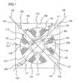
- FIG. 1 shows a cross-sectional view of a stator 100 and a rotor 200 of the electrical machine 300.
- a DC shunt electrical machine that can easily performs switching between forward and reverse is used as the electrical machine 300.
- another DC electrical machine may be used as the electrical machine 300.
- the electrical machine 300 is provided with the stator 100 on the field side and the rotor 200 on the armature side.
- the stator 100 and the rotor 200 are concentrically placed opposite to each other across a void.
- the rotor 200 is placed at the inner periphery side of the stator 100.
- the stator 100 is provided with a square-pillar-shaped stator (field) core and field coils 118 ⁇ 121 wound on the core.
- the stator core is provided with a cylindrical (hollow) yoke 109 (annular core) with a cross-sectional shape of a quadrilateral (square) exterior and a circular interior, and four magnetic poles 110 ⁇ 113 (toothed cores) that protrude from the inner surface of the yoke 109 (surface of the rotor side) to the inner diameter side (towards the rotor 200) and that are equally circumferentially placed.
- the yoke 109 and the four magnetic poles 110 ⁇ 113 are integrally formed.
- slots 114 ⁇ 117 in which the field coils 118 ⁇ 121 concentratedly wound on the core are placed, are provided between the circumferentially adjacent magnetic poles.
- the slot 114 is formed between the circumferentially adjacent magnetic poles 110 and 113, with the slot 115 between the magnetic poles 110 and 111, the slot 116 between the magnetic poles 111 and 112, and the slot 117 between the magnetic poles 112 and 113.
- the field coil 118 is concentratedly wound on the magnetic pole 110 and is placed in the slots 114 and 115;
- the field coil 119 is concentratedly wound on the magnetic pole 111 and is placed in the slots 115 and 116;
- the field coil 120 is concentratedly wound on the magnetic pole 112 and is placed in the slots 116 and 117;
- the field coil 121 is concentratedly wound on the magnetic pole 113 and is placed in the slots 117 and 114.
- the yoke 109 is provided with four through-holes 105 - 108 for inserting the fixing bolts through.
- the through-holes 105 - 108 pass through the yoke 109 from an end face in the axial direction toward the other end face.
- the yoke 109 is provided with the quadrilateral (square) exterior with four angles 101 ⁇ 104.
- the four magnetic poles 110 ⁇ 113 and the four through-holes 105 ⁇ 108 are provided in positions corresponding to the four angles 101 ⁇ 104.
- Diagonal lines which connect angles facing to each other, are drawn on the sectional view of the stator core as in FIG. 1 , namely a diagonal line 123 that connects the angle 101 and the angle 103 and a diagonal line 124 that connects the angle 102 and the angle 104.
- the magnetic pole 110 and the through-hole 105 which correspond to the angle 101 and the magnetic pole 112 and the through-hole 107 which correspond to the angle 103 are provided.
- the magnetic pole 111 and the through-hole 106 which correspond to the angle 102 and the magnetic pole 113 and the through-hole 108 which correspond to the angle 104 are provided.
- the magnetic poles 110 and 112 extend toward the rotor 200 along the diagonal line 123 and face to each other across the rotor 200 and a void.
- the magnetic poles 111 and 113 extend toward the rotor 200 along the diagonal line 124 and face to each other across the rotor 200 and a void.
- Each end of rotor side of the magnetic poles 110 ⁇ 113 extends along the rotor 200 circumferentially, and broadens toward the end.
- the stator core is provided by axially laminating thin steel sheets (e.g. silicon steel sheets) whose part corresponding to the yoke 109 and parts corresponding to the magnetic pole 110 ⁇ 113 are integrally formed.
- thin steel sheets e.g. silicon steel sheets
- the rotor 200 is provided with a rotor (armature) core and an armature coil 202 wound on the core.
- a plurality of axially extended rotor slots 201 are placed equally circumferentially on the periphery of the cylindrical rotor core.
- the armature coil 202 is stored in the plurality of rotor slots 201.
- the armature coil 202 is provided by axially inserting a plurality of segment conductors obtained from a rectangular wire with a rectangular cross section into the plurality of rotor slots 201 and by connecting the end of the plurality of segment conductors with a commutator (not figured herein) which rotates together with the rotor core on the opposite side of the insert side of the plurality of segment conductors.
- a brush (not figured) held in a brush holder (not figured) is pressed on the peripheral surface of the commutator. This causes the brush to contact with the commutator and establishes an electrical connection between the stator and the rotor.
- the brush is supplied with an armature current from the electrical generator 11 for driving. Therefore, the armature coil 202 is supplied with the armature current via the brush and the commutator. Through which segment conductor the armature current supplied to the armature coil 202 flows is determined according to the switching of a slide contact position between the commutator and the brush caused by rotation of the commutator.
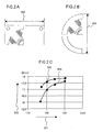
- Torque characteristics of the electrical machine 300 are now explained with reference to FIGS. 2A to 2C .
- FIG. 2C shows an analysis result of the torque characteristics of the electrical machine 300 in different external forms.
- FIG. 2A shows a model with the yoke 109 in a quadrilateral external form, in other words, with the stator 100 in a square pillar with a circular hollow. This model corresponds to the present embodiment.
- FIG. 2B shows another model with a yoke 109 in a circular external form, in other words, with a stator 100 in a cylindrical shape.
- FIG. 2C shows an analysis result of torque 502 generated corresponding to external form 501 of FIGS. 2A and 2B .
- the torque characteristic 503 of the model in FIG. 2A gives greater torque than the torque characteristic 504 of the model in FIG. 2B does. This is because of the following reason.
- the magnetic flux of the magnetic poles 110 ⁇ 113 produced by the field coils 118 ⁇ 121 is separated into right and left in the yoke 109, which is provided in the periphery of the magneticpoles, thereby flowing in R-shape.
- Increasing radius of the magnetic flux by radially-broadening the yoke 109, which is provided in the periphery of the magnetic poles 110 ⁇ 113 realizes reducedmagnetoresistance and increased flux content.
- the torque is increased. This is supported by that, in the model in FIG. 2B , the yoke 109, which is provided in the periphery of the magnetic poles, increased in volume by increasing the external form 501 brings increased torque.
- the magnetic pole 110 ⁇ 113 are provided corresponding to the four angles 101 ⁇ 104.
- the yoke 109 which is provided in the periphery of the magnetic poles, is radially-extended. Accordingly, radius of the magnetic flux that flows through the yoke 109 is increased.
- Lc Lc ⁇ La ⁇ Lb
- La the circumferential width at the end of the yoke side of the magnetic pole
- Lb the minimum radial width of a part of the yoke that corresponds to an area of the circumferential width La of the magnetic pole (yoke extension on the extended line of the magnetic pole), which is provided in the periphery of the magnetic pole
- Lc is the minimum radial width of a part of the yoke (yoke bridge) that connects between circumferentially adjacent yoke extensions.
- the magnetic flux flows magnetic paths from a magnetic path with width La of a magnetic pole to a magnetic path with width La of another magnetic pole via a magnetic path with the maximum width, a magnetic path with the minimum width, and the magnetic path with the maximum width in order.
- the magnetic flux flowing through a magnetic pole toward the outer periphery in a radial direction changes in circumferential direction with large radius in the yoke extension.
- the magnetic flux flowing through the yoke bridge in the circumferential direction changes in a radial direction towards the inner periphery with large radius in the yoke extension.
- the radial width of the yoke extension reaches its maximum on the extended line of the central axis of the magnetic pole.
- the magnetoresistance is reduced and the flux content is increased, thereby increasing the torque of the electrical machine 300.
- High power and miniaturization are thus achieved according to the present embodiment.
- the stator core consists of the laminated steel sheet made of axially laminated thin steel sheets. This construction is employed by the following reason.
- the direction of the armature current flowing through the armature coil 202 of the rotor 200 is switched by rotation of the rotor 200, and the magnetic flux is changed by the current change, an eddy current is generated in the stator core.
- the eddy current increases as the square of sheet thickness of the magnetic material. Therefore, the stator core is formed not of a single magnetic material but of the laminated steel sheet made of laminated thin steel sheets, thereby reducing the eddy current.
- the eddy current generated in the stator core can not be reduced to zero even using the laminated steel sheet made of laminated thin steel sheets.
- the eddy current acts between the thin steel sheets. This causes vibration or noise (magnetic noise) between the thin steel sheets.
- the change in the magnetic flux is great, e.g. when torque or rotational speed of the electrical machine 300 changes rapidly, the electromagnetic power between the rotor 200 and the thin steel sheets of the magnetic pole 110 ⁇ 113 becomes higher. Also under this circumstance, the magnetic noise becomes greater.
- the flux content is increased and the electromagnetic power between the thin steel sheets of the magnetic pole 110 ⁇ 113 and the rotor 200 is increased, thereby increasing the magnetic noise.
- the magnetic noise can be decreased by increasing the degree of contact between the thin steel sheets. Namely, the amplitude of vibration generated between the thin steel sheets can be limited.
- Increasing contact pressure between the thin steel sheets is effective for increasing the degree of contact between the thin steel sheets.
- the through-holes 105 ⁇ 108 are provided in the nearest part of the yoke to the magnetic poles 110 ⁇ 113, i.e. the yoke extension on the extended lines of the central axes of the magnetic poles, and the yoke 109 is fixed to the bracket with bolts through the through-holes 105 ⁇ 108.
- the contact pressure between the thin steel sheets on the magnetic poles 110 ⁇ 113 are thus increased, thereby reducing the magnetic noise.
- the through-holes 105 ⁇ 108 are provided in positions with low magnetic flux density and without any effect on torque characteristics of the electrical machine. Of areas with low magnetic flux density, providing the through-holes 105 ⁇ 108 in the closest position to the rotor is most effective for increasing the contact pressure between the thin steel sheets of the magnetic poles 110 ⁇ 113.
- the through-holes 105 ⁇ 108 are provided in the yoke extension so that the centers of the through-holes 105 ⁇ 108 are provided on the diagonal lines 123 and 124 (on the extended lines of the central axes of the magnetic poles).
- This enables a radial width h1 of the yoke 109 between the magnetic pole and the nearest part of the through-hole to the magnetic pole to be smaller than the minimum radial width h (at circumferentially intermediate position of the yoke bridge) of the yoke 109 in the area with low magnetic flux density.
- the through-holes 105 ⁇ 108 are thus provided in the closest position to the rotor.
- the thin steel sheets used for constituting the stator 100 are formed by punching steel strip sheets.
- the quadrilateral external form of the yoke 109 results in wasting materials less than a circular external form of the same does. According to the present embodiment, high productivity and easy handling for a punch die are thus achieved.
- a mounting configuration of the electrical machine 300 is now explained with reference to FIG. 3 .
- FIG. 3 shows the mounting configuration of the electrical machine 300 to a differential gear box 400, which is a chassis of the differential gear 14.
- a rear bracket 301 is shown in a cross section view passing through the center of a rotating shaft.
- the stator 100 is axially-sandwiched by the rear bracket 301 and a front bracket 302, and is thus fixed.
- Bolts 303 and 304 are inserted into the through-holes 105 and 108 respectively, pass through to the side of the differential gear box 400, and are screwed to the differential gear box 400.
- a rotating shaft 307 is pivotally supported by a rear bearing 308.
- the commutator of the rotor 200 In the front bracket 302, the commutator of the rotor 200, a current feed brush, a connecting terminal to be connected with an external feeder, and a front bearing that pivotally supports the rotating shaft of the rotor 200 are housed.
- the electrical machine 300 By screwing the bolts 303 and 304 to the differential gear box 400, the electrical machine 300 is fixed to the differential gear box 400 with the rotating shaft 307 (output shaft) meshing with the differential gear in the differential gear box 400.
- bolts 305 and 306 are inserted respectively through the through-holes 106 and 107 which are not figured herein and are screwed to the differential gear box 400.
- the electrical machine 300 thus assembled is vulnerable to external shock.
- the most typical example is that a stone is bounded on the road and hits the vehicle. If bolts that fixe the stator 100 are exposed, the bounded stone may hit the bolts and the bolts may be damaged and bent. This will result in disruption of the balance of tightening force at a plurality of fixing positions, thereby deforming the bolts and/or reducing the tightening force of the bolts.
- the electrical machine 300 in the present embodiment can thus prevent the bolts from being damaged.
- angles 101 ⁇ 104 are acute, they may be provided in an arc or chamfered. This is because the magnetic flux density is low at angles in the periphery due to the through-holes 105 ⁇ 108 and the torque characteristics of the electrical machine are not affected according to the shape of the periphery.
- the through-holes 105 ⁇ 108 and the magnetic poles 110 ⁇ 113 are arranged with the diagonal lines 123 and 124 as the center lines. However, they may be displaced as long as the torque characteristics of the electrical machine and noise from the vibration of the yoke 109 and the magnetic poles 110 ⁇ 113 are acceptable.
- the external form of the stator 100 (theyoke9) isasquare. However, it may be a rectangle.
- the through-holes 105 ⁇ 108 may be displaced from the diagonal lines of the angles as long as the magnetic noise or the torque characteristics are acceptable.
- the core of the stator 100 may consist of a compressed powder magneticmaterial.
- the electrical machine 300 is fixed to the differential gear box 400 without exposing the bolts 303 ⁇ 306, thereby preventing the bolts from being damaged.
- FIG. 5 shows a cross-sectional view of a stator 122 of the electrical machine according to the present embodiment.
- the external form of the stator is a quadrilateral (square).
- operations and advantageous effects described in the first embodiment can be achieved with another polygon.
- the external form of the stator 122 is a regular hexagon.
- Configurations are basically the same between the present embodiment and the first embodiment: the only difference is the number of magnetic poles and through-holes. Namely, six magnetic poles 129 ⁇ 134 and six through-holes 123 ⁇ 128 are provided corresponding to six angles of the stator 122 (yoke). In other words, the magnetic poles 129 ⁇ 134 and the through-holes 123 ⁇ 128 are placed on diagonal lines, as the center lines, which connect angles facing each other.
- the torque can be increased.
- bolts are passed through the through-holes 123 ⁇ 128 so as to fix the electrical machine to the bracket of the differential gear box. This increases the contact pressure between the thin steel sheets of the magnetic poles and reduces the magnetic noise.
- fixing bolts since fixing bolts are not exposed, damage to the bolts by external impact can be prevented.
- the electrical machine and the vehicle drive device equipped with the electrical machine according to the first and the second embodiments of the present invention improve magnetic properties.
- the magnetic properties include torque characteristics, magnetic noise characteristics, and the like, of the electrical machine.
Landscapes
- Engineering & Computer Science (AREA)
- Power Engineering (AREA)
- Iron Core Of Rotating Electric Machines (AREA)
Applications Claiming Priority (1)
| Application Number | Priority Date | Filing Date | Title |
|---|---|---|---|
| JP2007274582A JP2009106047A (ja) | 2007-10-23 | 2007-10-23 | 電動機およびそれを備えた車両駆動装置 |
Publications (2)
| Publication Number | Publication Date |
|---|---|
| EP2053722A2 true EP2053722A2 (de) | 2009-04-29 |
| EP2053722A3 EP2053722A3 (de) | 2010-10-06 |
Family
ID=40352292
Family Applications (1)
| Application Number | Title | Priority Date | Filing Date |
|---|---|---|---|
| EP08018563A Withdrawn EP2053722A3 (de) | 2007-10-23 | 2008-10-23 | Elektrische Maschine und Fahrzeug-Antrieb mit dieser Maschine |
Country Status (4)
| Country | Link |
|---|---|
| US (1) | US20090115282A1 (de) |
| EP (1) | EP2053722A3 (de) |
| JP (1) | JP2009106047A (de) |
| CN (1) | CN101420138A (de) |
Cited By (2)
| Publication number | Priority date | Publication date | Assignee | Title |
|---|---|---|---|---|
| WO2014023991A1 (es) * | 2012-08-09 | 2014-02-13 | Romero-Beltran Julian | Motor |
| WO2014031005A1 (en) * | 2012-08-20 | 2014-02-27 | Greenway Energy As | Coil slot for castellated variable reluctance motor (cvrm) |
Families Citing this family (15)
| Publication number | Priority date | Publication date | Assignee | Title |
|---|---|---|---|---|
| US20190068044A1 (en) * | 2010-01-25 | 2019-02-28 | Svetozar B. Petrovich | In Evolution of Gravity Fields |
| WO2011039769A2 (en) * | 2009-09-15 | 2011-04-07 | Kpit Cummins Infosystems Ltd. | Hybrid drive system with reduced power requirement for vehicle |
| CN102596672B (zh) | 2009-09-15 | 2015-03-04 | Kpit技术有限责任公司 | 根据预测的驱动变化向一种混合动力交通工具提供的引擎辅助 |
| MX2012003114A (es) | 2009-09-15 | 2012-06-19 | Kpit Cummins Infosystems Ltd | Metodo para convertir un vehiculo en un vehiculo hibrido. |
| JP5926182B2 (ja) * | 2009-09-15 | 2016-05-25 | ケーピーアイティ テクノロジーズ リミテッド | ユーザ入力に基づくハイブリッド車のモータ補助 |
| US8423214B2 (en) | 2009-09-15 | 2013-04-16 | Kpit Cummins Infosystems, Ltd. | Motor assistance for a hybrid vehicle |
| CN102247101B (zh) * | 2010-05-21 | 2015-07-22 | 德昌电机(深圳)有限公司 | 厨房电器 |
| AT510743B1 (de) * | 2010-11-18 | 2013-10-15 | Avl List Gmbh | Stromerzeugungsaggregat |
| CN103609008B (zh) * | 2011-06-09 | 2016-04-20 | 东芝三菱电机产业系统株式会社 | 旋转电机 |
| JP5653984B2 (ja) | 2012-10-17 | 2015-01-14 | ファナック株式会社 | コギングトルクを低減する固定子コアを有する電動機 |
| JP6298233B2 (ja) * | 2013-02-06 | 2018-03-20 | 三星エスディアイ株式会社SAMSUNG SDI Co., LTD. | モータ制御方法及びモータ制御システム |
| CN109245339A (zh) * | 2017-07-11 | 2019-01-18 | 上海鸣志电器股份有限公司 | 一种步进电机定子及具有该定子的电机 |
| JP2019176542A (ja) * | 2018-03-27 | 2019-10-10 | 株式会社ミツバ | 電動モータ |
| CN112713672B (zh) * | 2019-10-25 | 2022-03-22 | 佛山市威灵洗涤电机制造有限公司 | 电机及其装配结构 |
| KR102750677B1 (ko) * | 2020-04-03 | 2025-01-07 | 현대자동차주식회사 | 전동화 차량의 엔진 클러치 제어 방법 |
Citations (2)
| Publication number | Priority date | Publication date | Assignee | Title |
|---|---|---|---|---|
| JP2006109691A (ja) | 2004-10-02 | 2006-04-20 | Bosch Rexroth Ag | 電気機械のための固定子 |
| JP2007274582A (ja) | 2006-03-31 | 2007-10-18 | Oki Electric Ind Co Ltd | 監視映像管理システム |
Family Cites Families (7)
| Publication number | Priority date | Publication date | Assignee | Title |
|---|---|---|---|---|
| US1654840A (en) * | 1925-04-09 | 1928-01-03 | Honeywell Heating Specialties | Induction motor |
| JPH08115815A (ja) * | 1994-10-17 | 1996-05-07 | Nkk Corp | 多極鉄心 |
| DE19633194C2 (de) * | 1996-08-17 | 1998-09-17 | Daimler Benz Ag | Serieller Hybridantrieb, insbesondere für ein Kraftfahrzeug |
| JP2001211574A (ja) * | 2000-01-20 | 2001-08-03 | Techno Excel Co Ltd | 電動機の固定子鉄心 |
| JP2003274579A (ja) * | 2002-03-18 | 2003-09-26 | Matsushita Electric Ind Co Ltd | 密閉型圧縮機用電動機の固定子 |
| CN2652017Y (zh) * | 2003-01-03 | 2004-10-27 | 张芳溥 | 家用风扇的二极马达定子改良结构 |
| DE10337915A1 (de) * | 2003-08-18 | 2005-04-14 | Vorwerk & Co. Interholding Gmbh | Reluktanzmotor |
-
2007
- 2007-10-23 JP JP2007274582A patent/JP2009106047A/ja active Pending
-
2008
- 2008-10-17 CN CNA2008101666866A patent/CN101420138A/zh active Pending
- 2008-10-22 US US12/256,278 patent/US20090115282A1/en not_active Abandoned
- 2008-10-23 EP EP08018563A patent/EP2053722A3/de not_active Withdrawn
Patent Citations (2)
| Publication number | Priority date | Publication date | Assignee | Title |
|---|---|---|---|---|
| JP2006109691A (ja) | 2004-10-02 | 2006-04-20 | Bosch Rexroth Ag | 電気機械のための固定子 |
| JP2007274582A (ja) | 2006-03-31 | 2007-10-18 | Oki Electric Ind Co Ltd | 監視映像管理システム |
Cited By (4)
| Publication number | Priority date | Publication date | Assignee | Title |
|---|---|---|---|---|
| WO2014023991A1 (es) * | 2012-08-09 | 2014-02-13 | Romero-Beltran Julian | Motor |
| US20150372574A1 (en) * | 2012-08-09 | 2015-12-24 | Julian Romero-Beltran | Single-phase shaded pole induction motor, convertible to permanent magnet motor |
| US10164507B2 (en) * | 2012-08-09 | 2018-12-25 | Julián Romero-Beltran | Single-phase shaded pole induction motor, convertible to permanent magnet motor |
| WO2014031005A1 (en) * | 2012-08-20 | 2014-02-27 | Greenway Energy As | Coil slot for castellated variable reluctance motor (cvrm) |
Also Published As
| Publication number | Publication date |
|---|---|
| CN101420138A (zh) | 2009-04-29 |
| US20090115282A1 (en) | 2009-05-07 |
| JP2009106047A (ja) | 2009-05-14 |
| EP2053722A3 (de) | 2010-10-06 |
Similar Documents
| Publication | Publication Date | Title |
|---|---|---|
| EP2053722A2 (de) | Elektrische Maschine und Fahrzeug-Antrieb mit dieser Maschine | |
| US7781930B2 (en) | Accessory drive system with RD motor | |
| JP4013487B2 (ja) | 回転電機及びそれを搭載した車両 | |
| US6452302B1 (en) | Rotary electric machine and electric vehicle using the same | |
| US10886808B2 (en) | Electric linear actuator | |
| US20120235535A1 (en) | Rotary electric machine | |
| JP2009124902A (ja) | 回転電機およびそれを備えた車載用電機システム | |
| CN101355268A (zh) | 混合动力车辆的皮带传动交流发电机起动器马达发电机 | |
| JP2006217752A (ja) | 回転電機 | |
| KR20110021749A (ko) | 파워 발생 장치 | |
| US11456643B2 (en) | Rotating electric machine, controller, vehicle system, and maintenance method of rotating electric machine | |
| US20190326790A1 (en) | Brushless starter rotor assembly | |
| US8689916B2 (en) | Apparatus of driving wheels for in-wheel system | |
| US20120133227A1 (en) | Motor drive system arrangement to reduce torque ripple | |
| KR101938889B1 (ko) | 모터와 알터네이터를 융합한 전동차용 인휠 시스템 | |
| WO2015019746A1 (ja) | ステータコア | |
| US10938259B2 (en) | Stator having bobbin-embedded tooth tips | |
| KR101765581B1 (ko) | 모터 회전자 가변 장치 | |
| JP2011114997A (ja) | 回転電機及びこれを利用した電動パワーステアリング装置用モータ | |
| WO2021002103A1 (ja) | 減速機付モータ | |
| JP3047798B2 (ja) | 車両用駆動装置 | |
| EP3846325B1 (de) | Motor und elektrisches fahrzeug damit | |
| JP2011125180A (ja) | ステータ | |
| JP2000092800A (ja) | 車両用交流発電機 | |
| JP2019520027A (ja) | クローポール形電気モータ |
Legal Events
| Date | Code | Title | Description |
|---|---|---|---|
| PUAI | Public reference made under article 153(3) epc to a published international application that has entered the european phase |
Free format text: ORIGINAL CODE: 0009012 |
|
| AK | Designated contracting states |
Kind code of ref document: A2 Designated state(s): AT BE BG CH CY CZ DE DK EE ES FI FR GB GR HR HU IE IS IT LI LT LU LV MC MT NL NO PL PT RO SE SI SK TR |
|
| AX | Request for extension of the european patent |
Extension state: AL BA MK RS |
|
| 17P | Request for examination filed |
Effective date: 20090415 |
|
| PUAL | Search report despatched |
Free format text: ORIGINAL CODE: 0009013 |
|
| AK | Designated contracting states |
Kind code of ref document: A3 Designated state(s): AT BE BG CH CY CZ DE DK EE ES FI FR GB GR HR HU IE IS IT LI LT LU LV MC MT NL NO PL PT RO SE SI SK TR |
|
| AX | Request for extension of the european patent |
Extension state: AL BA MK RS |
|
| AKX | Designation fees paid |
Designated state(s): DE FR GB IT |
|
| STAA | Information on the status of an ep patent application or granted ep patent |
Free format text: STATUS: THE APPLICATION IS DEEMED TO BE WITHDRAWN |
|
| 18D | Application deemed to be withdrawn |
Effective date: 20110407 |