EP2053430A2 - Lichtsteuerungsplatte, Oberflächenlichtquellenvorrichtung und übertragende Bildanzeigevorrichtung - Google Patents
Lichtsteuerungsplatte, Oberflächenlichtquellenvorrichtung und übertragende Bildanzeigevorrichtung Download PDFInfo
- Publication number
- EP2053430A2 EP2053430A2 EP08253419A EP08253419A EP2053430A2 EP 2053430 A2 EP2053430 A2 EP 2053430A2 EP 08253419 A EP08253419 A EP 08253419A EP 08253419 A EP08253419 A EP 08253419A EP 2053430 A2 EP2053430 A2 EP 2053430A2
- Authority
- EP
- European Patent Office
- Prior art keywords
- light
- incident
- path control
- parts
- light path
- Prior art date
- Legal status (The legal status is an assumption and is not a legal conclusion. Google has not performed a legal analysis and makes no representation as to the accuracy of the status listed.)
- Withdrawn
Links
Images










Classifications
-
- G—PHYSICS
- G02—OPTICS
- G02B—OPTICAL ELEMENTS, SYSTEMS OR APPARATUS
- G02B5/00—Optical elements other than lenses
- G02B5/02—Diffusing elements; Afocal elements
- G02B5/0273—Diffusing elements; Afocal elements characterized by the use
- G02B5/0278—Diffusing elements; Afocal elements characterized by the use used in transmission
-
- G—PHYSICS
- G02—OPTICS
- G02B—OPTICAL ELEMENTS, SYSTEMS OR APPARATUS
- G02B5/00—Optical elements other than lenses
- G02B5/04—Prisms
-
- G—PHYSICS
- G02—OPTICS
- G02B—OPTICAL ELEMENTS, SYSTEMS OR APPARATUS
- G02B3/00—Simple or compound lenses
- G02B3/02—Simple or compound lenses with non-spherical faces
- G02B3/08—Simple or compound lenses with non-spherical faces with discontinuous faces, e.g. Fresnel lens
-
- G—PHYSICS
- G02—OPTICS
- G02B—OPTICAL ELEMENTS, SYSTEMS OR APPARATUS
- G02B5/00—Optical elements other than lenses
- G02B5/02—Diffusing elements; Afocal elements
-
- G—PHYSICS
- G02—OPTICS
- G02B—OPTICAL ELEMENTS, SYSTEMS OR APPARATUS
- G02B5/00—Optical elements other than lenses
- G02B5/04—Prisms
- G02B5/045—Prism arrays
Definitions
- the present invention relates to a light control plate, a surface light source device, and a transmission type image display apparatus.
- surface light source devices In transmission type image display apparatus such as liquid crystal display apparatus, surface light source devices have been in use as light sources for outputting backlight for liquid crystal display parts.
- An example of such surface light source devices is one disclosed in Patent Document 1.
- This surface light source device is constructed such that a light diffuser is placed in front of a plurality of light sources arranged separated from each other within a lamp box.
- the light diffuser is provided with a deflection structure part having such a form that light incident thereon from the plurality of light sources can be emitted substantially perpendicular to the surface of the light diffuser.
- the light fed from the plurality of light sources can be diffused while being guided to the front side of the surface of the light diffuser, so that parallel light having a uniform luminance distribution can be outputted as backlight.
- Patent Document Japanese Patent Application Laid-Open No. 2006-351519
- the above-mentioned surface light source device can output parallel light having a uniform luminance distribution as explained, there are cases where unevenness occurs in resulting pictures and an appropriate viewing angle is to be secured, for example, depending on the purpose of use of the surface light source device, and one in which the light emitted from the surface light source device is widened within a predetermined emission angle range is also demanded.
- the present invention provides a light control plate arranged separated from a plurality of light sources disposed with a gap therebetween, the light control plate having a main face facing the plurality of light sources and a flat exit surface opposing the main face and emitting light from the plurality of light sources incident on the main face; wherein a corresponding area for a space between two of the light sources adjacent to each other in the main face has first and third regions formed with a plurality of first light path control parts, arranged in the disposing direction of the plurality of light sources, for widening first incident light within a predetermined angle range and emitting thus widened light from the exit surface, and a second region arranged between the first and third regions and formed with at least one second light path control part for emitting second incident light within the predetermined angle range from the exit surface; wherein the first incident light is a light component outputted from the light source closer to the first light path control part in the two adjacent light sources; wherein the second incident light is constituted by respective light components outputted from the two adjacent light sources; where
- the first to third regions within each corresponding area in the main face are arranged in order from the first to third regions in the disposing direction. Therefore, the first region is positioned on one light source side in the adjacent two light sources, while the third region is positioned on the other light source side.
- respective light components from the light sources closer to the first and third regions are incident on the first and third regions, respectively, whereby light from the light source closer to the first light path control part in the two adjacent light sources is incident on the first light path control part as the first incident light.
- each of the light components from the two adjacent light sources is incident on the second region positioned between the first and third regions, whereby each of the light components outputted from the two adjacent light sources is incident on the second light path control part as the second incident light.
- the first and third regions located closer to the light sources are formed with a plurality of first light path control parts.
- first incident light is incident on the first light path control part
- the first incident light is emitted from the exit surface as being widened within a predetermined angle range by refraction by a plurality of planar parts in the first light path control part.
- the second region positioned between the first and third regions is formed with a plurality of second light path control parts.
- the second incident light incident on the second light path control part is emitted from the exit surface as being widened within the predetermined angle range by total reflection within a plurality of prism parts in the second light path control part.
- each of the light components incident on the first and second light path control parts is emitted as being widened into the predetermined angle range, whereby the light widened into the predetermined angle range can be emitted from the exit surface.
- respective angles of inclination of the plurality of planar parts with respect to the exit surface are defined such that the first incident light incident on each planar part is refracted in such a direction as to be emitted from the exit surface with an output angle within the predetermined angle range; each of the plurality of prism parts has first and second side faces; the angles of inclination of the first and second side faces with respect to the exit surface are defined such that the second incident light incident on the second side face is totally reflected by the first side face in such a direction as to be emitted from the exit surface with an output angle within the predetermined angle range, while the second incident light incident on the first side face is totally reflected by the second side face in such a direction as to be emitted from the exit surface with an output angle within the predetermined angle range; the second incident light incident on the first side face is a light component outputted from the light source closer to the first side face in the adjacent two light sources; and the second incident light incident on the second side
- the first incident light can be emitted from the exit surface with an output angle within the predetermined angle range by utilizing refraction of the first incident light incident on each planar part.
- the output angle of the first incident light from the exit surface which is determined by the respective angles of inclination of the planar parts with respect to the exit surface, is appropriately allocated within the predetermined angle range, the first incident light incident on the first light path control part can be widened into the predetermined angle range.
- each of the prism parts in the second light path control part has first and second side faces, while the angles of inclination of the first and second side faces with respect to the exit surface are defined as mentioned above, the second incident light incident on the first and second side faces can be emitted from the exit surface with an output angle within the predetermined angle range by utilizing total reflection within the prism parts.
- the output angle of the second incident light from the exit surface which is determined by the angles of inclination of the first and second side faces, is appropriately allocated within the predetermined angle range, the second incident light incident on the second light path control part can be widened into the predetermined angle range as in the first light path control part.
- the first incident light components incident on the plurality of planar parts have respective output angles different from each other; angles selected at fixed angle intervals from within the predetermined angle range are allocated to the second incident light components totally reflected by the respective first side faces in the plurality of prism parts; and angles selected at fixed angle intervals from within the predetermined angle range are allocated to the second incident light components totally reflected by the respective second side faces in the plurality of prism parts.
- the first and second incident light components respectively incident on the first and second light path control parts are easier to widen to the predetermined angle range.
- the second region has a plurality of second light path control parts.
- the second region has a plurality of second light path control parts, light can be widened into the predetermined angle range more securely.
- the plurality of planar parts in the first light path control parts have respective sizes defined such that light components incident on the plurality of planar parts and then emitted from the exit surface within the predetermined angle range have a substantially uniform luminance angle distribution in the predetermined angle range.
- the first light path control part is formed in the first and third regions that are closer to the light source than is the second region. Therefore, the first light path control part is more susceptible to the luminance distribution of the light outputted from the light source.
- the luminance angle distribution of the light einitted from the exit surface tends to become substantially constant.
- each of the first and third regions has a fourth region positioned directly above the light source and a fifth region positioned between the second and fourth regions; the fourth region is formed with at least one of the plurality of first light path control parts; the first light path control part within the fourth region has a recessed cross-sectional form, while the plurality of planar parts in the first light path control part are arranged in series so as to construct a surface of the first light path control part; the fifth region is formed with a plurality of first light path control parts; and a step is formed between planar parts adjacent to each other and positioned on the second or fourth region side in the plurality of planar parts in each of the first light path control parts within the fifth region.
- the first light path control part having a recessed cross-sectional form can be formed, while a surface of the first light path control part can be constructed by a plurality of planar parts.
- the first incident light component is likely to advance in a direction oblique to the above-mentioned normal direction, so as to be made incident on the first light path control region.
- positions of both ends of the first light path control part may deviate from each other in the above-mentioned normal direction under the influence of the angles of inclination of the planar parts and the like.
- the size of the step can make the positions of both ends of the first light path control part in the above-mentioned normal direction coincide with each other. As a result, the light control plate can be formed while keeping a desirable thickness.
- the surface light source device in accordance with the present invention comprises a plurality of light sources disposed with a gap therebetween, and the light control plate in accordance with the present invention arranged separated from the plurality of light sources.
- respective light components outputted from the plurality of light sources pass through the light control plate, so as to be emitted from the exit surface of the light control plate.
- the light components from two light sources adjacent to each other in the plurality of light sources are incident on corresponding areas for the two light sources in the light control plate, they are emitted from the exit surface as being widened into the predetermined angle range as mentioned above, whereby the above-mentioned surface light source device can yield emission light widened into the predetermined angle range.
- the transmission type image display apparatus in accordance with the present invention comprises the surface light source device in accordance with the present invention, and a transmission type image display part arranged separated from the surface light source device in a direction substantially orthogonal to the disposing direction of the plurality of light sources in the surface light source device.
- the emission light widened into the predetermined angle range outputted from the surface light source device is incident on the transmission type image display apparatus.
- a wider viewing angle can be secured as compared with a case where parallel light is incident on the transmission type image display part, for example.
- Fig. 1 is a sectional view schematically showing the structure of one embodiment of the transmission type image display apparatus in accordance with the present invention.
- the transmission type image display apparatus 1 is a liquid crystal display apparatus which is constructed such that a surface light source device 50 is provided behind (under) a transmission type image display part 10 formed by laminating polarizing plates 12, 13 on the upper and lower faces of a liquid crystal cell 11, respectively.
- the side arranged with the transmission type image display part 10 is referred to as "upper" or "front" side of the surface light source device 50.
- liquid crystal cell 11 and polarizing plates 12, 13, those used in conventional transmission type image display apparatus such as liquid crystal display apparatus can be employed.
- the liquid crystal cell 11 include known liquid crystal cells of TFT and STN types.
- a pair of the upper and lower polarizing plates 12, 13 are arranged in a state where their respective transmission axes are orthogonal to each other, while these transmission axes are arranged parallel to the orientation direction of liquid crystal molecules in the liquid crystal cell 11.
- the surface light source device 50 has a light source part 20 and a light control plate 40 which is arranged separated from the light source part 20 on the front side thereof, i.e., on the transmission type image display part 10 side. By using the light control plate 40, the surface light source device 50 collects light F i outputted from the light source part 20 and supplies thus collected light as backlight to the transmission type image display part 10.
- the light source part 20 has a plurality of light sources 30 for outputting the light F i , while the plurality of light sources 30 are disposed at equally-spaced intervals L so that the respective center axes of the light sources 30 are positioned within the same plane.
- the interval L between the center axes of the light sources 30, 30 adjacent to each other is 15 mm to 150 mm, for example.
- Each light source 30 is shaped like a rod extending in a direction orthogonal to the disposing direction of the plurality of light sources 30, an example of which is one shaped like a straight tube such as fluorescent lamp (cold cathode fluorescent tube). Though the light source 30 is shaped like a rod here, point light sources such as LED can also be used.
- the plurality of light sources 30 are preferably arranged within a lamp box 35 as shown in Fig. 1 , while the inner face 35a of the lamp box 35 is preferably formed as a light reflecting surface. In this case, the light F i fed from the light sources 30 can reliably be outputted to the transmission type image display part 10 side.
- the light control plate 40 has a substantially rectangular parallelepiped form and covers all of the plurality of light sources 30.
- the light control plate 40 is arranged separated from the light source part 20 by 5 mm to 50 mm, for example.
- the thickness of the light control plate 40 is 0.1 to 15 mm, for example, preferably 0.5 mm to 10 mm, more preferably 1 mm to 5 mm.
- the light control plate 40 is made of a transparent material, e.g., transparent resin or transparent glass.
- transparent resin include polycarbonate resins, ABS resins (acrylonitrile/styrene/butadiene copolymer resins), methacrylic resins, MS resins (methyl methacrylate/styrene copolymer resins), polystyrene resins, AS resins (acrylonitrile/styrene copolymer resins), and polyolefin resins such as polyethylene and polypropylene.
- the light control plate 40 may contain a small amount of diffusing agents. Slight diffusion is permissible on surfaces.
- the light control plate 40 widens the light F i , which is incident thereon from a rear face (main face) 40a side, within a predetermined angle range with respect to a normal N to an exit face 40b arranged opposite to the rear face 40a and emits thus widened light.
- ⁇ be the output angle with respect to the normal N to the exit surface 40b
- ⁇ max be the maximum output angle
- the light control plate 40 widens the incident light F i within the range of - ⁇ max ⁇ ⁇ ⁇ ⁇ max and emits thus widened light as light F o from the exit surface 40b.
- ⁇ max is 20°, for example.
- a plurality of fine structures for emitting the light F i within a predetermined angle range are formed in respective areas 41 corresponding to the spaces between pairs of light sources 30, 30 adjacent to each other.
- the structure of the corresponding area 41 will now be explained.
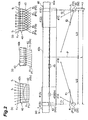
- Fig. 2 is a schematic view enlarging a portion of a light control plate.
- Fig. 2 enlarges a portion of the light control plate 40 including one corresponding area 41 and also illustrates its corresponding two light sources 30, 30 adjacent to each other for convenience.
- one (on the left side in Fig. 2 ) of the two light sources 30, 30 in Fig. 2 will also be referred to as a light source 31, while the other will also be referred to as a light source 32.
- the respective light components F i outputted from the light sources 31 and 32 will also be referred to as light components F1 i and F2 i , respectively.
- the light components F1 i and F2 i will also be explained as assemblies of a plurality of light beams f1 i , f2 i
- the light F o will also be explained as an assembly of light beams f o .
- the z-axis direction be the direction in which the light sources 31, 32 are arranged (the horizontal direction in Fig. 2(a) )
- the y-axis direction be the direction, orthogonal to the z axis, in which the light control plate 40 is positioned with respect to the light source 31, and the x-axis direction be the direction orthogonal to the y-and z-axis directions.
- the corresponding area 41 is constituted by first to third regions 41A, 41B, 41C.
- the first and third regions 41A, 41C include areas directly above the light sources 31, 32 and are positioned on both sides of the second area 41B.
- the corresponding area 41 is constructed such that their halves (left and right halves in Fig. 2 ) are symmetric about the center position between the two light sources 31, 32, i.e., a virtual plane P arranged orthogonal to the exit surface 40b at a position distanced by L/2 from the light source 31 to the light source 32. Therefore, the structures of the half region of the corresponding area 41 on the light source 31 side, i.e., the first region 41A, and the half of the second region 41B on the first area 41A side will mainly be explained.
- the first and second regions 41A, 41B have a plurality of light path control parts (first and second light path control parts) 42 and 43 as fine structures extending in the x-axis direction (one direction).
- a plurality of light path control parts 42 are densely formed in the z-axis direction within the first region 41A.
- a plurality of light path control parts 43 are densely formed in the z-axis direction within the second region 41B.
- the width (length in the z-axis direction) of each of the light path control parts 42, 43 is 50 ⁇ m to 10 mm, for example, preferably 50 ⁇ m to 5 nm, more preferably 50 ⁇ m to 2 mm.
- the light path control part 42 is constructed such as to include a plurality of planar parts tilted at different angles with respect to a plane substantially parallel to the output surface 40b.
- the light path control part 42 is used for widening the light F1 i as first incident light, which is incident on the light path control part 42 after being outputted from the closer light source 31 in the two light sources 31, 32, within the angle range of at least - ⁇ max but not greater than ⁇ max with respect to the normal N to the exit surface 40b and outputting thus widened light from the exit surface 40b.
- the plurality of light path control parts 42 can be dividend into light path control parts 42 0 which are formed directly above the light source 31 and receive the light beams f1 i substantially parallel to the normal N to the exit surface 40b, and light path control parts 42 k (where k is an integer of 1 or greater) where the light beams f1 i tilted with respect to the normal N are incident.
- the fourth region 41 A 1 is formed with the light path control part 42 0
- the fifth region 41A 2 is formed with the light path control parts 42 k .
- the fourth region 41A 1 may have a plurality of light path control parts 42 0 depending on the size of the fourth region 41A 1 , the distance between the control plate 40 and light source 31, and the like.
- the light path control part 43 is constructed such as to include a plurality of prism parts.
- the light path control part 43 is used for outputting the light components F1 i , F2 i as the second incident light, which are incident on the light path control part 43 after being outputted from the two light sources 31, 32, within a predetermined angle range of at least - ⁇ max but not greater than ⁇ max with respect to the normal N to the exit surface 40b from the exit surface 40b by utilizing total reflection within the prism parts.
- the light path control part 43 is arranged such that light components F1 i , F2 i incident on the prism parts are totally reflected within the prism parts, so as to be outputted as being widened within the output angle range mentioned above.
- the third region 41C is constructed such as to include a plurality of light path control parts 42, while these light path control parts 42 can be constituted by light path control parts 42 0 and 42 k .
- the third region 41C can be constituted by fourth and fifth regions 41C 1 and 41C 2 corresponding to the fourth and fifth regions 41A 1 and 41A 2 in the first region 41A.
- the fourth region 41C 1 is formed with the light path control part 42 0
- the fifth region 41C 2 is formed with the light path control parts 42 k .
- the fourth region 41C 1 may have a plurality of light path control parts 42 0 as with the first region 41A.
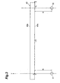
- Fig. 3 shows the positional relationship between the light control plate and a three-dimensional coordinate system which is used for convenience in the explanation of this embodiment.
- Fig. 3 also shows the light sources 31, 32 for illustrating the positional relationship between the light control plate 40 and the light sources 31, 32 in the three-dimensional coordinate system.
- the three-dimensional coordinate system composed of x, y, and z axes is assumed such that the position directly above the light source 31 in the rear face 40a (i.e., the position directly above the center of the light source 31) when no fine structures are supposed to be formed is taken as its origin O.
- H be the distance between the x axis and the light sources 31, 32, i.e., the distance between the light control plate 40 and the light sources 31, 32.
- the distance H is 5 mm to 50 mm, for example.
- Figs. 4 and 5 are partly enlarged views of the area directly above the light source in the light control plate.
- Fig. 5 schematically shows an example of light paths of a plurality of light beams f1 i constituting the first incident light incident on the light path control part 42 0 .
- the light path control part 42 0 is a fine structure extending in the x-axis direction and having a substantially recessed cross-sectional form.
- the surface of the light path control part 42 0 is constituted by first to Mth planar parts 44 0.1 to 44 0,M whose number is M (where M is an integer of 2 or greater).
- the first to Mth planar parts 44 0,1 to 44 0,M are provided in series. Letting the planar part 44 0,m (where m is an integer, of at least 1 but not greater than M) be the mth planar part in the first to Mth planar parts 44 0,1 to 44 0,M , the planar part 44 0,m is parallel to or tilted with respect to a plane parallel to the exit surface 40b.
- the angle of inclination ⁇ 0,m of the planar part 44 0,m with respect to the exit surface 40b is defined such that the light incident on the planar part 44 0,m is emitted from the exit surface 40b with an output angle ⁇ 0,m .
- the output angle ⁇ 0,m may be any angle within the predetermined angle range (at least - ⁇ max but not greater than ⁇ max ).
- the output angles ⁇ 0,1 to ⁇ 0,M cover the whole angle range mentioned above. More preferably, the output angles ⁇ 0,1 to ⁇ 0,M are allocated at fixed intervals within the' predetermined angle range mentioned above.
- the right-handed direction (clockwise direction) with respect to the y-axis direction is referred to as positive direction in the output angle ⁇ 0,m .
- the sizes of the first to Mth planar parts 44 0,1 to 44 0,M are defined such that I( ⁇ 0,1 ) to I( ⁇ 0,M ) which are respective luminances of the light beams f o emitted to the directions of the output angles ⁇ 0,1 to ⁇ 0,M become the same.
- the size of the planar part 44 0,m can be determined by defining its pitch ratio L 0,m , shown in Fig. 4 according to the transmittance of the light control plate 40 with respect to the light beam f1 i incident on the planar part 44 0,m and the output angle ⁇ 0,m of the light beam f 0 corresponding to the light beam f1 j .
- n be the refractive index of the light control plate 40
- n i be the refractive index of a medium (e.g., air) in contact with the rear face 40a of the light control plate 40
- n o be the refractive index of a medium (e.g., air) in contact with the exit surface 40b of the light control plate 40 in the following explanation.
- a three-layer structure including the light control plate 40 as its intermediate layer is assumed.
- ⁇ 0,m is the angle of incidence of the light beam f1 i with respect to the exit surface 40b after being refracted upon incidence on the planar part 44 0,m (see Fig. 5 ).
- t 1s 0 , m and t 1p 0,m which are respective transmittances of the planar part 44 0,m with respect to the Sand P-polarized components of the light beam f1 i at its incidence position
- t 2s 0,m and t 2p 0,m which are respective transmittances of the planar part 44 0,m with respect to the S- and P-polarized components of the light beam f1 i at its exit position on the exit surface 40b
- the planar parts 44 0,1 to 44 0,m are designed by defining the angles of inclination ⁇ 0,1 to ⁇ 0,M and the pitch ratios L 0,1 to L 0,M by utilizing expressions (1) to (12), the light beams f1 i incident on the planar parts 44 0,1 to 44 0,M can be emitted from the exit surface 40b with the output angles ⁇ 0,1 to ⁇ 0,M defined by expression (3). Therefore, the light path control part 42 0 having the first to Mth planar parts 44 0,1 to 44 0,M can expand the incident light F1 i within a predetermined angle range and emit thus widened light from the exit surface 40b. Since the pitch ratios L 0,1 to L 0,M are defined by utilizing expressions (4) and (5), a uniform luminance angle distribution can be attained within the predetermined angle range.
- Fig. 6 is an enlarged view of a part including a portion of the first region in the light path control part.
- Fig. 6 schematically shows the structure of the light control plate including the kth light path control part 42 k seen from the light path control part 42 0 .
- the light path control part 42 k has M planar parts, i.e., first to Mth planar parts 44 k,1 to 44 k,M .
- Each of the first to Mth planar parts 44 k,1 to 44 k,M extends in the x-axis direction. Letting the planar part 44 k,m (where m is an integer of at least 1 but not greater than M) be the mth planar part in the first to Mth planar parts 44 k,1 to 44 k,M , the planar part 44 k,m is parallel to or tilted with respect to a plane parallel to the exit surface 40b.
- the angle of inclination ⁇ k,m of the planar part 44 k,m with respect to the exit surface 40b is defined such that the light incident on the planar part 44 k,m is emitted from the exit surface 40b with an output angle ⁇ k,m .
- the right-handed direction (clockwise direction) in the drawing is referred to as positive direction in the output angle ⁇ k,m here as well.
- the output angle ⁇ k,m may be any angle within the predetermined angle range (at least - ⁇ max but not greater than ⁇ max ).
- the output angles ⁇ k,1 to ⁇ k,M cover the whole angle range mentioned above. More preferably, the output angles ⁇ k,1 to ⁇ k,M are allocated at fixed intervals within the predetermined angle range mentioned above.
- the size of the planar part 44 k,m can also be represented by a solid angle ratio of the planar part 44 k,m seen from the light source 31.
- This solid angle ratio corresponds to the light beams f1 i entering from the first to Mth planar parts 44 k,1 to 44 k,M , and can be defined such that I( ⁇ k,1 ) to I( ⁇ k,M ) which are respective luminances of the light beams f o emitted from the exit surface 40b to the directions of the output angles ⁇ k,1 to ⁇ k,M become the same by utilizing the respective transmittances of the light control plate 40 with respect to the light beams f1 i incident on the first to Mth planar parts 44 k,1 to 44 k,M and the output angles ⁇ k,1 to ⁇ k,M .
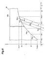
- FIGs. 7 and 8 are partly enlarged views of a light control plate model for explaining an example of methods of defining the angles of inclination ⁇ k,1 to ⁇ k,M and sizes.
- t 1s k,m and t 1p k,m which are respective transmittances of the planar part 44 k,m with respect to the Sand P-polarized components of the light beam f1 i at its incidence position
- t 2s k,m and t 2p k,m which are respective transmittances of the exit surface 40b with respect to the S- and P-polarized components of the light beam f1 i at its exit position
- z k,0 be the z-coordinate at the end on the origin O side (i.e., directly above the light source 31) of the light path control part 42 k .
- z k,0 is represented by (Z k +Z k-1 )/2.
- H is the distance between the center of the light source 31 and the origin O, i.e., the distance from the center of the light source 31 to the rear face 40a when no fine structures such as light path control part 42 k,m are supposed to be formed.
- ⁇ k,m is the angle formed by the line connecting the center of the light source 31 and the end of the planar part 44 k,m on the origin O side and the z-axis direction.
- the angle of inclination ⁇ k,m and solid angle ratio ⁇ k,m of the mth planar part 44 k,m in the light path control part 42 k are determined according to expressions (13) to (26).
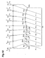
- a step S is provided between two adjacent planar parts (planar parts 41 k,m , 44 k,m+1 in Fig. 10 ) on one side (left side in Fig. 10 ) of both ends 42a k , 42b k of the light path control part 42 k such that both ends 42a k , 42b k have the same y-coordinate.
- the step S is provided between each pair of adjacent planar parts in the planar parts 44 k,1 to 44 k,5 .
- a slope 45 is formed by providing the step S such that the light refracted by one of the two planar parts forming the slope 45 is not inhibited by the slope 45 from advancing.
- the slope 45 connecting the planar parts 44 k,1 , 44 k,2 is formed substantially parallel to the advancing direction (refracting direction) of the light beam f1 i refracted by the planar part 44 k,2 .
- This restrains the step S from further refracting the light beam f1 i , whereby the light beam f o can be emitted from the exit surface 40b with a desirable output angle defined by expression (15).
- the steps S may be arranged on the right side of Fig. 10 in the light path control part 42 k instead of the left side illustrated here.
- the planar part 44 k,m may be designed while assuming that Y k , which is the y-coordinate of the end 42a k on the origin O side of each light path control part 42 k , is 0 in the designing of the light path control part 42 k .
- the angle of inclination ⁇ k,m and size of each planar part 44 k,m may be rearranged by a similar technique, i.e., using Snell's low, such that the light f1 i incident on each planar part 44 k,m is emitted from the exit surface 40b with a desirable output angle.
- the light path control part 42 k is a structure which is typically much smaller than the distance H between the light source 31 and light control plate 40 and thus hardly affects the luminance angle distribution.
- the light path control part 42 k is constructed by a polygonal lens part in which the planar parts 44 k,m are connected in series, and a prism area part having at least one prism part including the planar part 44 k,m and slope 45 as side faces.
- the angles of inclination ⁇ k,1 to ⁇ k,M and sizes of the first to Mth planar parts 44 k,1 to 44 k,M are defined by utilizing expressions (13) to (26) as mentioned above, the light beams f1 i incident on the first to Mth planar parts 44 k,1 to 44 k,M can be emitted from the exit surface 40b with output angles defined by expression (15) as shown in Fig. 10 .
- the light F1 i incident on the light path control part 42 k can be emitted as being widened within the predetermined angle range.
- the light F1 i incident on the light path control part 42 k can be emitted as light having a uniform luminance angle distribution within the predetermined angle range.
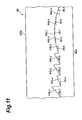
- the first to Mth planar parts 44 k,1 to 44 k,M designed by utilizing expressions (13) to (26) may be partly rearranged as shown in Fig. 11 so as to maximize the emission efficiency, i.e., make the slope 45 smaller.
- Fig. 12 is a schematic view of an example of the light path control part in the second region. Fig. 12 partly enlarges a portion of the light control plate 40 including the light path control part 43.
- the light path control part 43 has first to Mth prism parts 46 1 to 46 M each extending in the x-axis direction and having a substantially triangular cross-sectional form. As shown in Fig. 12 , the first to Mth prism parts 46 1 to 46 M are projected downward and are formed such that their prism apexes 46a 1 to 46a M are positioned on the same plane.
- the structure of the mth prism part 46 m (where m is an integer of at least 1 but not greater than M) in the first to Mth prism parts 46 1 to 46 M will now be explained.
- the prism part 46 m has two intersecting side faces (tilted surfaces) 46b m , 46c m .
- the side face (tilted surface) 46b m , 46c m receives light from one of the two light sources 31, 32 that is closer thereto.
- the prism, part 46 m is constructed such that the light beam f1 i from the light source 31 on the side face 46b m side is refracted toward the side face 46c m by the side face 46b m and then totally reflected by the side face 46c m , so as to be emitted from the exit surface 40b with an output angle ⁇ ⁇ m , while the light beam f2 i from the light source 32 on the side face 46c m side is refracted toward the side face 46b m by the side face 46c m and then totally reflected by the side face 46b m , so as to be emitted, from the exit surface 40b with an output angle ⁇ ⁇ m .
- the right-handed direction (clockwise direction) in the drawing is referred to as positive direction in the output angles ⁇ ⁇ m , ⁇ ⁇ m .
- the output angles ⁇ ⁇ m , ⁇ ⁇ m are values within a predetermined angle range (at least - ⁇ max but not greater than ⁇ max ) and preferably cover the whole predetermined angle range. It will be preferred if the output angles ⁇ ⁇ 1 to ⁇ ⁇ M are allocated at fixed intervals within the predetermined angle range mentioned above. Similarly, it will be preferred if the output angles ⁇ ⁇ 1 to ⁇ ⁇ M are allocated at fixed intervals within the predetermined angle range mentioned above.
- the output angles ⁇ ⁇ m , ⁇ ⁇ m of light incident on the prism part 46 m are determined by defining the respective angles of inclination ⁇ m , ⁇ m of the side faces 46b m , 46c m with respect to a plane parallel to the exit surface 40b, while the form of the prism part 46 m is determined by defining the angles of inclination ⁇ m , ⁇ m .
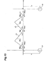
- Fig. 13 is a view showing a light control plate model for explaining a method of defining the angles of inclination ⁇ m , ⁇ m .
- the three-dimensional coordinate system shown in Fig. 13 is the same as that shown in Fig. 3 .
- the right-handed direction is the positive direction of the angle of inclination ⁇ m
- the left-handed direction is the positive direction of the angle of inclination ⁇ m .
- the respective positions at which the light beams f1 i , f2 i from the light sources 31, 32 are totally reflected are assumed to be midpoints p 1 m , p 2 m of the tilted surfaces 46b m , 46c m of the prism part 46 m .
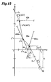
- Figs. 14 and 15 are views for explaining the method of defining angles of inclination ⁇ m , ⁇ m of two side faces in the prism part.
- Figs. 14 and 15 schematically show the prism part 46 m and illustrate the exit surface 40b and light sources 31, 32 for explanation.
- ⁇ ⁇ H m ⁇ - ⁇ ⁇ z m ⁇ tan ⁇ m
- ⁇ ⁇ z m ⁇ - z m - z m 2 ⁇ tan 2 ⁇ ⁇ m - 0.5 ⁇ ⁇ + ⁇ m ⁇ + y m 2 tan ⁇ m + tan 2 ⁇ ⁇ m - 0.5 ⁇ ⁇ + ⁇ m ⁇ .
- ⁇ H ⁇ m and ⁇ z ⁇ m represented by expressions (32) and (33) are correction terms by which the deviation between the position at which the light beam f1 i is incident on the prism part 46 m by totally reflecting the light beam f1 i at the position of the point p 2 m as shown in Fig. 14 and the position of the prism apex 46a m is corrected with respect to the z- and y-axis directions.
- ⁇ ⁇ m is the angle by which the light totally reflected by the side face 46c m is incident on the exit surface 40b as shown in Fig. 14 , and ⁇ ⁇ m ⁇ 0 in the incident direction of Fig. 14 .
- ⁇ ⁇ H m ⁇ ⁇ ⁇ z m ⁇ tan ⁇ m
- ⁇ ⁇ z m ⁇ - z m 1 - z m ⁇ tan 2 ⁇ ⁇ m - 0.5 ⁇ ⁇ - ⁇ m ⁇ + y m 1 tan ⁇ m + tan 2 ⁇ ⁇ m - 0.5 ⁇ ⁇ - ⁇ m ⁇ .
- ⁇ z ⁇ m and ⁇ H ⁇ m represented by expressions (37) and (38) are correction terms by which the deviation between the position at which the light beam f2 i is incident on the prism part 46 m by totally reflecting the light beam f2 i at the position of the point p 1 m as shown in Fig. 15 and the position of the prism apex 46a m is corrected with respect to the z- and y-axis directions.
- the light path control part 43 can widen the incident light components F1, F2 within the predetermined angle range and emit thus widened light components.
- the structure of the corresponding area 41 on the light source 32 side of the plane P shown in Fig. 2 i.e., the structure of the second region 41B from the position of the plane P to the third region 41C and the third region 41C, corresponds to the reverse about the plane P of the structure of the first region 41A and the second region 4 1 B from the first region 41A to the plane P. Therefore, designing the structure of the first region 41A and the second region 41B from the first region 41A to the plane P can design the structure of the rear face 40a of the light control plate 40.
- the boundary position between the first and second regions 41A, 41B and the boundary position between the second and third regions 41B, 41C are determined such that local luminance angle distributions of light components emitted from the exit surface 40b are connected as smoothly as possible to each other.
- the structures of light path control parts 42 0 , 42 k , 43 to be formed in the corresponding area 41 are designed by utilizing expressions (1) to (12), (13) to (26), and (27) to (38) as mentioned above.
- the steps S are provided as appropriate when designing the structures of the light path control part 42 k .
- a planar body made of a transparent material having flat front and rear faces is prepared, and its rear face is cut at predetermined positions by a microfabrication technique, so as to form the light path control parts 42 0 , 42 k , 43 designed as mentioned above, thereby yielding the light control plate 40.
- the light path control parts 42 0 , 42 k , 43 are formed such that the rear face of the planar body corresponds to the xz plane shown in Fig. 3 .
- both ends of the light path control parts 42 0 , 42 k and the prism apexes 46a 1 to 46a M of the prism parts 46 1 to 46 M in the light path control part 43 are formed on the same plane.
- the light components F1, F2 outputted from the two light sources 31, 32 adjacent to each other in a plurality of light sources 30 are incident on the light control plate 40 from the rear face 40a of the light control plate 40.
- the light path control parts 42 0 , 42 k , 43 are formed in the first to third regions 41A to 41C of each corresponding area 41 in the rear face 40a of the light control plate 40, respectively.
- the respective incident light components through the light path control parts 42 0 , 42 k , 43 are emitted from the exit surface 40b as being widened within the predetermined angle range in each emission region therefor.
- the emission light F o widened within the predetermined angle range is emitted from the exit surface 40b.
- control plate 40 It is also important for the light, control plate 40 to form the light path control parts 42 0 , 42 k in the first and third regions 41A, 41C and form the light path control part 43 in the second region 41B held between the first and third regions 41A, 41C.
- the first and third regions 41A, 41C in the rear face 40a of the light control plate 40 mainly receive light from the light sources 30 closer to them.
- the inclination of the incident light with respect to the y-axis direction is so small that the light can be emitted as being widened into the predetermined angle range by utilizing the refraction of light upon incidence on the first to Mth planar parts 44 0,1 to 44 0,M , 44 k,1 to 44 k,M .
- the light incident on the second region 41B tends to tilt greater with respect to the y-axis direction.
- the light can be widened into the predetermined angle range more reliably by utilizing the total reflection within the prism parts 46 1 to 46 M .
- forming the light path control parts 42 0 , 42 k in the first and third regions 41A, 41C and forming the light path control part 43 in the second region 41B as in the light control plate 40 can widen the light components F1 i , F2 i incident on the light control plate 40 into the predetermined angle range and emit thus widened light as mentioned above.
- the transmission type image display apparatus 1 constructed such that the light F o from the surface light source device 50 is incident on the transmission type image display part 10 as shown in Fig. 1 , the light F o widened into the predetermined angle range is incident on the transmission type image display part 10. Hence, a viewing angle corresponding to the predetermined angle range can be secured.
- a plurality of light sources 30 emit light in various directions
- light components from the plurality of light sources 30 are converged into the predetermined angle range by utilizing the above-mentioned light control plate 40.
- the luminance of the light F o emitted from the light control plate 40 can be made higher within the predetermined angle range.
- the direction of refraction of incident light is adjusted in the light path control parts 42 0 , 42 k such that a fixed luminance angle distribution is attained within the predetermined angle range, whereby the luminance angle distribution is likely to become uniform in the emission light F o . Therefore, employing the surface light source device 50 in the transmission type image display apparatus 1 reduces unevenness in pictures and the like and easily adapts it to larger sizes in the transmission type image display apparatus 1 and the like.
- Fig. 17 is a schematic view of a simulation model including the light control plate.
- the simulation model is constructed by a plurality of light sources 30 aligned at equally-spaced intervals L in the z-axis direction, a light control plate 40 arranged separated by a distance H from the light sources 30, and a light reflecting surface 35a corresponding to the inner face 35a of the light box shown in Fig. 1 .
- Each light source 30 is supposed to be one shaped like a rod having a radius of 1 mm, while the distance (center-to-center distance) L between the adjacent light sources 30 is 30 mm.
- the distance H between the light control plate 40 and the light sources 30 is 20 mm.
- the distance H corresponds to the distance between the center of each light source 30 and the main face 40a in the light control plate 40 having no light path control parts 42, 43, and is specifically the distance between a plane including the centers of a plurality of light sources 30 and a plane including a plurality of prism apexes 46a m .
- the thickness of the light control plate 40 is 2 mm.
- the light control plate 40 is placed in air and has a refractive index of 1.57277.
- the distance h between the light reflecting surface 35a and the centers of the light sources 30 is 5 mm.
- a region having a width W1 in the z-axis direction centered at a position (origin position in the drawing) directly above each light source 30 in the light control plate 40 is defined as one unit (hereinafter referred to as light control unit) 40A, and the light control plate 40 is supposed to be constructed by connecting the respective light control units 40A corresponding to the light sources 30 in the z-axis direction.
- the light control unit 40A corresponds to an area between planes P which include the center positions in the z-axis direction of corresponding areas 41 adjacent to each other in the light control plate 40 and are parallel to the xy plane shown in Fig. 17 .
- the width W1 is 30 mm in this simulation.
- the rear face 40a of the light control unit 40A is formed with light path control parts 42 0 , 42 k , 43, each having a width of 1.0 mm in the z-axis direction, which are designed by utilizing expressions (1) to (38)
- M was 9 in each of the light path control parts 42 0 , 42 k , 43, the maximum output angle ⁇ max was 20°, and the width of each of the light path control parts 42 0 , 42 k , 43 in the z-axis direction was 1.0 mm.
- H 20 mm
- the luminance I( ⁇ ) used when defining the structures of the light path control parts 42 0 , 42 k by utilizing expressions (1) to (26) was 1 within the range of - ⁇ max ⁇ ⁇ ⁇ ⁇ max .
- one light source 30 corresponds to one light control unit 40A
- the structure of the rear face in the light control unit 40A is designed while also taking account of light from the light source 30 corresponding to the light control unit 40A adjacent to the one to be designed as can be understood from the explanation concerning expressions (1) to (3 8).
- the structure of the rear face 40a in the light control unit 40A will now be explained specifically.
- Fig. 18 is a chart showing an area where -0.5 ⁇ z ⁇ 0.5 in the light control unit and illustrating the light path control part 42 0 .
- the light path control part 42 0 is designed by using expressions (1) to (12).
- the angles of inclination ⁇ 0,1 to ⁇ 0,9 and pitch ratios L 0,1 to L 0,9 are as shown in Table 1. Since the width of the light path control part 42 0 is 1.0 mm, the pitch ratios correspond to the respective lengths of the planar parts in the z-axis direction. Therefore, Table 1 employs (mm) as the unit for pitch ratio L 0,m . [TABLE 1] m ⁇ 0, m (° ) L 0, m (mm) 1 32. 584 0. 107 2 25. 148 0. 110 3 17. 137 0. 112 4 8. 688 0. 113 5 0. 000 0. 114 6 8. 688 0. 113 7 17. 137 0. 112 8 25. 148 0. 110 9 32. 584 0. 107
- Fig. 19 is a chart showing an area where 0.5 ⁇ z ⁇ 1.5 in the light control unit and illustrating the light path control part 42 1 .
- angles of inclination ⁇ 1,1 to ⁇ 1,9 and positional coordinates of ends of the planar parts 44 1,1 to 44 1,9 were determined by utilizing expressions (13) to (26).
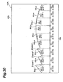
- a step S was provided between each adjacent pair of the planar parts 44 1,1 to 44 1,3 in order for both ends of the light path control part 42 1 to attain the same height in the y-axis direction, thus yielding the structure shown in Fig. 20 .
- Fig. 20 In Fig.
- ⁇ 1 , ⁇ 2 which are angles of inclination of tilted surfaces constituting the steps S with respect to a plane parallel to the exit surface 40b shown in Fig. 19 are 80.528° and 83.661°, respectively.
- Fig. 20 is a chart showing an area where 1.5 ⁇ z ⁇ 2.5 in the light control unit and illustrating the light path control part 42 2 .
- angles of inclination ⁇ 2,1 to ⁇ 2,9 and positional coordinates of ends of the planar parts 44 2,1 to 44 2,9 were determined by utilizing expressions (13) to (26).
- steps S are provided in order for both ends of the light path control part 42 2 to have the same height in the y-axis direction.
- the planar parts 44 2,2 and 44 2,3 designed by utilizing expressions (13) to (26) are rearranged.
- ⁇ 1 , ⁇ 2 , ⁇ 3 which are angles of inclination of tilted surfaces constituting the steps S with respect to a plane parallel to the exit surface 40b shown in Fig. 20 are 83.661°, 80.528°, and 86.823°, respectively.
- Fig. 21 is a chart showing an area where 2.5 ⁇ z ⁇ 3.5 in the light control unit and illustrating the light path control part 42 3 .
- angles of inclination ⁇ 3,1 to ⁇ 3,9 and positional coordinates of ends of the planar parts 44 3,1 to 44 3,9 were determined by utilizing expressions (13) to (26).
- steps S are provided in order for both ends of the light path control part 42 3 to have the same height in the y-axis direction.
- the planar parts 44 3,2 to 44 3,4 designed by utilizing expressions (13) to (26) are rearranged.
- ⁇ 1 , ⁇ 2 , ⁇ 3 , ⁇ 4 which are angles of inclination of tilted surfaces constituting the steps S with respect to a plane parallel to the exit surface 40b shown in Fig. 21 are 86.823°, 80.528°, 83.661°, and 90.000°, respectively.
- Fig. 22 is a chart showing an area where 3.5 ⁇ z ⁇ 4.5 in the light control unit and illustrating the light path control part 42 4 .
- angles of inclination ⁇ 4,1 to ⁇ 4,9 and positional coordinates of ends of the planar parts 44 4,1 to 44 4,9 were determined by utilizing expressions (13) to (26).
- steps S are provided in order for both ends of the light path control part 42 4 to have the same height in the y-axis direction.
- the planar parts 44 4,2 to 44 4,5 designed by utilizing expressions (13) to (26) are rearranged.
- ⁇ 1 , ⁇ 2 , ⁇ 3 , ⁇ 4 , ⁇ 5 which are angles of inclination of tilted surfaces constituting the steps S with respect to a plane parallel to the exit surface 40b shown in Fig. 22 are 90.000°, 80.528°, 86.823°, 83.661°, and 90.000°, respectively.
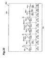
- Fig. 23 is a chart showing an area where 4.5 ⁇ z ⁇ 5.5 in the light control unit and illustrating the light path control part 42 5 .
- angles of inclination ⁇ 5,1 to ⁇ 5,9 and positional coordinates of ends of the planar parts 44 5,1 to 44 5,9 wee determined by utilizing expressions (13) to (26).
- steps S are provided in order for both ends of the light path control part 42 5 to have the same height in the y-axis direction.
- the planar parts 44 5,2 to 44 5,6 designed by utilizing expressions (13) to (26) are rearranged.
- ⁇ 1 , ⁇ 2 , ⁇ 3 , ⁇ 4 , ⁇ 5 , ⁇ 6 which are angles of inclination of tilted surfaces constituting the steps S with respect to a plane parallel to the exit surface 40b shown in Fig. 23 are 90.000°, 80.528°, 90.000°, 83.661°, 86.823°, and 90.000°, respectively.
- each light path control part 43 has nine prism parts.
- ⁇ ⁇ m , ⁇ ⁇ m were allocated in the light path control part 43 as shown in Table 7.
- Tables 8 to 17 show calculated results of angles of inclination ⁇ m , ⁇ m of side faces 46b m , 46c m in the prism parts in the light path control parts 43 under the foregoing condition.
- Tables 8 to 17 show the angles of inclination ⁇ m , ⁇ m of side faces 46b m , 46c m in their prism parts.
- Table 8 shows only the angle of inclination ⁇ m of the side face 46c m without showing ⁇ m , since this corresponds to the boundary between the first and second regions 41A and 41B.
- the structure of the area where -15.0 ⁇ z ⁇ -0.5 is mirror symmetric to the structure of the area where 0.5 ⁇ z ⁇ 15.0 about the depicted xy plane.
- Results of a simulation of luminance angle distribution for the above-mentioned light control unit 40A will now be explained.
- the simulation was performed for the area between two planes P shown in Fig. 17 . Specifically, the simulation was performed while assuming periodic boundary conditions at the position of the plane P with respect to the z-axis direction and at both ends of a predetermined area (having a width of 112 mm in the x-axis direction in this example). Ray tracing was employed as a simulation technique.
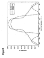
- Fig. 24 is a view showing the results of simulation of luminance angle distribution.
- the abscissa and ordinate in Fig. 24 indicate output angle and luminance, respectively.
- a luminance angle distribution as simulation results in the light control unit 40A is represented by a solid line as an example in Fig. 24 .
- a luminance angle distribution obtained when combining a conventional diffuser with a prism sheet formed with a plurality of prism parts each having an apex angle of 90° instead of using the light control plate 40 is represented by a broken line as a comparative example in Fig. 24 .
- the illumination method and boundary condition in the comparative example are the same as those in the example.
- the light control plate 40 in this example can realize a high luminance within the range of -20° to 20°, and can mainly converge and output light within the range of 20° to 20°.
- This example controls the output angle better and can make the luminance angle distribution more uniform within the range of -20° to 20° as compared with the comparative example.
- the corresponding area 41 has such a structure that its halves are symmetric about its center position, and defining the structure of one half of the corresponding area 41 can omit defining the structure of the remaining half.
- the structure of the remaining half may newly be defined by a similar method.
- the structure of the light path control part 42 0 located in the fourth regions 41A 1 , 41C 1 is defined while assuming that light is incident thereon in a direction parallel to the normal N.
- the structure may be determined by utilizing an expression similar to that in the case of the light path control part 42 k .
- the sizes of the first to Mth planar parts 44 0,1 to 44 0,M , 44 k,1 to 44 k,m are defined such that light incident on the first light path control parts 42 0 , 42 k attains a fixed luminance angle distribution within a predetermined angle range. For widening the light within the predetermined angle range and emitting thus widened light, however, it will be sufficient if at least the angles of inclination of the first to Mth planar parts 44 0,1 to 44 0,M , 44 k,1 to 44 k,M are defined.
- the structure of the light path control parts 42 0 , 42 k can also be determined without defining the pitch ratios L 0,1 to L 0,M and solid angle ratios ⁇ k,1 to ⁇ k,M of the first to Mth planar parts 44 0,1 to 44 0,M , 44 k,1 to 44 k,M .
- the light path control part 42 k having no steps S can be designed.
- a plurality of light control units 40A corresponding to respective light sources 30 may be made and arranged in parallel, so as to yield one light control plate 40.
- the present invention can relate to a light control plate which is arranged separated from a plurality of light sources 30 disposed in parallel and has respective light control units 40A corresponding to the light sources 30, wherein the rear face (main face) 40a of each light control unit 40A is constituted by a first region 41A including an area directly above the light source 30 and second regions 4 1 B provided on both sides of the first region 4 1 A, and wherein a plurality of light control units 40A are arranged in the disposing direction of the light sources 30.
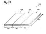
- Fig. 25 is a schematic view of an example of a light control plate constituted by three light control units 40A.
- the light control plate 100 shown in Fig. 25 is constructed by connecting three light control units 40A, each extending in one direction, in series in a direction substantially orthogonal to the extending direction.
- the length W2 of each light control unit 40A in its extending direction shown in Fig. 25 is 90 mm, for example, while the width of each light control unit 40A is 30 mm, for example, as in the simulation.
Landscapes
- Physics & Mathematics (AREA)
- General Physics & Mathematics (AREA)
- Optics & Photonics (AREA)
- Planar Illumination Modules (AREA)
- Liquid Crystal (AREA)
- Illuminated Signs And Luminous Advertising (AREA)
- Optical Elements Other Than Lenses (AREA)
Applications Claiming Priority (1)
| Application Number | Priority Date | Filing Date | Title |
|---|---|---|---|
| JP2007277958A JP2009104073A (ja) | 2007-10-25 | 2007-10-25 | 光制御板、面光源装置及び透過型画像表示装置 |
Publications (2)
| Publication Number | Publication Date |
|---|---|
| EP2053430A2 true EP2053430A2 (de) | 2009-04-29 |
| EP2053430A3 EP2053430A3 (de) | 2009-08-26 |
Family
ID=40289466
Family Applications (1)
| Application Number | Title | Priority Date | Filing Date |
|---|---|---|---|
| EP08253419A Withdrawn EP2053430A3 (de) | 2007-10-25 | 2008-10-22 | Lichtsteuerungsplatte, Oberflächenlichtquellenvorrichtung und übertragende Bildanzeigevorrichtung |
Country Status (6)
| Country | Link |
|---|---|
| US (1) | US20090109657A1 (de) |
| EP (1) | EP2053430A3 (de) |
| JP (1) | JP2009104073A (de) |
| KR (1) | KR20090042179A (de) |
| CN (1) | CN101418936A (de) |
| TW (1) | TW200923431A (de) |
Cited By (3)
| Publication number | Priority date | Publication date | Assignee | Title |
|---|---|---|---|---|
| EP2362250A1 (de) * | 2010-02-26 | 2011-08-31 | Research In Motion Limited | Lichtleiter zur Verbesserung einer Vorrichtungsbeleuchtung |
| US8319764B2 (en) | 2009-06-29 | 2012-11-27 | Research In Motion Limited | Wave guide for improving light sensor angular response |
| US8403539B2 (en) | 2010-02-26 | 2013-03-26 | Research In Motion Limited | Light guide for improving device lighting |
Families Citing this family (3)
| Publication number | Priority date | Publication date | Assignee | Title |
|---|---|---|---|---|
| JP5059171B2 (ja) * | 2009-07-06 | 2012-10-24 | 住友化学株式会社 | 光制御板、面光源装置及び透過型画像表示装置 |
| KR102437389B1 (ko) * | 2016-12-13 | 2022-08-26 | 엘지디스플레이 주식회사 | 액정표시장치 |
| CN107357059B (zh) * | 2017-08-24 | 2020-05-19 | 深圳市华星光电技术有限公司 | 阵列基板、彩色滤光片基板及液晶面板 |
Citations (1)
| Publication number | Priority date | Publication date | Assignee | Title |
|---|---|---|---|---|
| JP2006351519A (ja) | 2005-05-20 | 2006-12-28 | Sumitomo Chemical Co Ltd | 面光源装置及び透過型画像表示装置 |
Family Cites Families (13)
| Publication number | Priority date | Publication date | Assignee | Title |
|---|---|---|---|---|
| JP4168179B2 (ja) * | 1995-03-03 | 2008-10-22 | スリーエム カンパニー | 種々の高さの構造化面を有する光指向性フィルム及び該フィルムから作製された光指向性製品 |
| JP4293300B2 (ja) * | 2001-05-24 | 2009-07-08 | シャープ株式会社 | 照明装置およびそれを備える表示装置 |
| US7318644B2 (en) * | 2003-06-10 | 2008-01-15 | Abu-Ageel Nayef M | Compact projection system including a light guide array |
| US7301701B2 (en) * | 2003-06-10 | 2007-11-27 | Abu-Ageel Nayef M | Compact polarization conversion system for optical displays |
| TWI240829B (en) * | 2003-12-12 | 2005-10-01 | Ind Tech Res Inst | Light-guide type diffusive uniform light device |
| JP4438441B2 (ja) * | 2004-02-16 | 2010-03-24 | 日本電気株式会社 | 照明装置及びそれを備える表示装置 |
| JP4425164B2 (ja) * | 2004-04-12 | 2010-03-03 | 株式会社クラレ | 照明装置およびこれを用いた画像表示装置 |
| JP4487629B2 (ja) * | 2004-05-14 | 2010-06-23 | 凸版印刷株式会社 | 面照明装置及びそれを用いた液晶表示装置 |
| JP4873683B2 (ja) * | 2005-04-19 | 2012-02-08 | チェイル インダストリーズ インコーポレイテッド | 面光源装置 |
| JP2007095386A (ja) * | 2005-09-27 | 2007-04-12 | Nippon Zeon Co Ltd | 直下型バックライト装置 |
| JPWO2007055115A1 (ja) * | 2005-11-11 | 2009-04-30 | 日本ゼオン株式会社 | 直下型バックライト装置 |
| FR2905479B1 (fr) * | 2006-08-31 | 2008-10-31 | Saint Gobain | Systeme optique pour dispositif d'eclairage, dispositif d'eclairage et procede de pilotage du dispositif |
| JP2008312059A (ja) * | 2007-06-15 | 2008-12-25 | Panasonic Corp | アドホックネットワーク構成方法及びノード装置 |
-
2007
- 2007-10-25 JP JP2007277958A patent/JP2009104073A/ja active Pending
-
2008
- 2008-10-22 EP EP08253419A patent/EP2053430A3/de not_active Withdrawn
- 2008-10-22 US US12/255,703 patent/US20090109657A1/en not_active Abandoned
- 2008-10-24 KR KR1020080104553A patent/KR20090042179A/ko not_active Withdrawn
- 2008-10-24 TW TW097140918A patent/TW200923431A/zh unknown
- 2008-10-27 CN CNA2008101691054A patent/CN101418936A/zh active Pending
Patent Citations (1)
| Publication number | Priority date | Publication date | Assignee | Title |
|---|---|---|---|---|
| JP2006351519A (ja) | 2005-05-20 | 2006-12-28 | Sumitomo Chemical Co Ltd | 面光源装置及び透過型画像表示装置 |
Cited By (3)
| Publication number | Priority date | Publication date | Assignee | Title |
|---|---|---|---|---|
| US8319764B2 (en) | 2009-06-29 | 2012-11-27 | Research In Motion Limited | Wave guide for improving light sensor angular response |
| EP2362250A1 (de) * | 2010-02-26 | 2011-08-31 | Research In Motion Limited | Lichtleiter zur Verbesserung einer Vorrichtungsbeleuchtung |
| US8403539B2 (en) | 2010-02-26 | 2013-03-26 | Research In Motion Limited | Light guide for improving device lighting |
Also Published As
| Publication number | Publication date |
|---|---|
| US20090109657A1 (en) | 2009-04-30 |
| EP2053430A3 (de) | 2009-08-26 |
| CN101418936A (zh) | 2009-04-29 |
| TW200923431A (en) | 2009-06-01 |
| KR20090042179A (ko) | 2009-04-29 |
| JP2009104073A (ja) | 2009-05-14 |
Similar Documents
| Publication | Publication Date | Title |
|---|---|---|
| CN1038879C (zh) | 具有多次反射光注入系统并采用微棱镜的背照光照明系统 | |
| US7661863B2 (en) | Prism sheet including reflective elements with different curvature surfaces | |
| CN101487945B (zh) | 光学片和具有该光学片的显示装置 | |
| AU2011314771B2 (en) | Backlight unit | |
| KR100618601B1 (ko) | 프레넬렌즈 시트 및 이를 구비한 투과형 스크린 | |
| US11921314B2 (en) | Display device and backlight module thereof | |
| EP2053430A2 (de) | Lichtsteuerungsplatte, Oberflächenlichtquellenvorrichtung und übertragende Bildanzeigevorrichtung | |
| US20080192484A1 (en) | Optical sheet and display device including the same | |
| TW201539049A (zh) | 面光源裝置及顯示裝置 | |
| CN105745558A (zh) | 棱镜片、面光源装置、映像源单元及液晶显示设备 | |
| CN110268311B (zh) | 用于在水平平面中增强视图的具有转向膜和透镜状匀光片的光控制膜 | |
| KR20140066237A (ko) | 백라이트 장치 | |
| US20090003001A1 (en) | Optical path deflecting plate, surface light source device and transmissive image display device | |
| JP2009163245A (ja) | 光学シート及びこれを有する表示装置 | |
| US7753544B2 (en) | Light control plate, surface light source device and transmissive image display device | |
| CN101329032B (zh) | 背光模块及其集光元件 | |
| JP2012032537A (ja) | 光偏向板、面光源装置及び透過型画像表示装置 | |
| KR100786384B1 (ko) | 광학 시트 및 상기 광학 시트가 구비된 액정표시장치의백라이트 어셈블리 | |
| KR101621567B1 (ko) | 광제어판, 면광원 장치 및 투과형 화상 표시 장치 | |
| US20220019014A1 (en) | Light control film with turning film and lenticular diffuser for view enhancement in the horizontal plane | |
| US20140160574A1 (en) | Optical sheet, backlight unit including the same, and display apparatus including the same | |
| US11320580B2 (en) | Light directing sheet, backlight module, and display device | |
| CN216210241U (zh) | 一种hud背光系统 | |
| JP2011113866A (ja) | 導光板、面光源装置および表示装置 | |
| JP2011138707A (ja) | プリズムシート、面光源装置および表示装置 |
Legal Events
| Date | Code | Title | Description |
|---|---|---|---|
| PUAI | Public reference made under article 153(3) epc to a published international application that has entered the european phase |
Free format text: ORIGINAL CODE: 0009012 |
|
| AK | Designated contracting states |
Kind code of ref document: A2 Designated state(s): AT BE BG CH CY CZ DE DK EE ES FI FR GB GR HR HU IE IS IT LI LT LU LV MC MT NL NO PL PT RO SE SI SK TR |
|
| AX | Request for extension of the european patent |
Extension state: AL BA MK RS |
|
| PUAL | Search report despatched |
Free format text: ORIGINAL CODE: 0009013 |
|
| AK | Designated contracting states |
Kind code of ref document: A3 Designated state(s): AT BE BG CH CY CZ DE DK EE ES FI FR GB GR HR HU IE IS IT LI LT LU LV MC MT NL NO PL PT RO SE SI SK TR |
|
| AX | Request for extension of the european patent |
Extension state: AL BA MK RS |
|
| 17P | Request for examination filed |
Effective date: 20100222 |
|
| AKX | Designation fees paid |
Designated state(s): CZ NL PL SK |
|
| REG | Reference to a national code |
Ref country code: DE Ref legal event code: 8566 |
|
| 17Q | First examination report despatched |
Effective date: 20100422 |
|
| STAA | Information on the status of an ep patent application or granted ep patent |
Free format text: STATUS: THE APPLICATION IS DEEMED TO BE WITHDRAWN |
|
| 18D | Application deemed to be withdrawn |
Effective date: 20101103 |