EP2052171B1 - Bürstendichtung für eine Strömungsmaschine und Strömungsmaschine mit einer solchen Bürstendichtung - Google Patents
Bürstendichtung für eine Strömungsmaschine und Strömungsmaschine mit einer solchen Bürstendichtung Download PDFInfo
- Publication number
- EP2052171B1 EP2052171B1 EP07802585A EP07802585A EP2052171B1 EP 2052171 B1 EP2052171 B1 EP 2052171B1 EP 07802585 A EP07802585 A EP 07802585A EP 07802585 A EP07802585 A EP 07802585A EP 2052171 B1 EP2052171 B1 EP 2052171B1
- Authority
- EP
- European Patent Office
- Prior art keywords
- brush seal
- bristles
- film
- disk
- seal according
- Prior art date
- Legal status (The legal status is an assumption and is not a legal conclusion. Google has not performed a legal analysis and makes no representation as to the accuracy of the status listed.)
- Not-in-force
Links
- 239000002184 metal Substances 0.000 claims abstract description 6
- 239000000463 material Substances 0.000 claims abstract description 5
- OKTJSMMVPCPJKN-UHFFFAOYSA-N Carbon Chemical compound [C] OKTJSMMVPCPJKN-UHFFFAOYSA-N 0.000 claims abstract description 4
- 229910002804 graphite Inorganic materials 0.000 claims abstract description 4
- 239000010439 graphite Substances 0.000 claims abstract description 4
- 239000011159 matrix material Substances 0.000 claims abstract description 4
- 238000007789 sealing Methods 0.000 claims description 8
- 230000000694 effects Effects 0.000 description 5
- 239000011888 foil Substances 0.000 description 2
- 241000904500 Oxyspora paniculata Species 0.000 description 1
- 239000003082 abrasive agent Substances 0.000 description 1
- 238000005452 bending Methods 0.000 description 1
- 230000001419 dependent effect Effects 0.000 description 1
- 238000011161 development Methods 0.000 description 1
- 230000018109 developmental process Effects 0.000 description 1
- 239000012530 fluid Substances 0.000 description 1
- 239000012528 membrane Substances 0.000 description 1
- 238000012856 packing Methods 0.000 description 1
Images


Classifications
-
- F—MECHANICAL ENGINEERING; LIGHTING; HEATING; WEAPONS; BLASTING
- F01—MACHINES OR ENGINES IN GENERAL; ENGINE PLANTS IN GENERAL; STEAM ENGINES
- F01D—NON-POSITIVE DISPLACEMENT MACHINES OR ENGINES, e.g. STEAM TURBINES
- F01D11/00—Preventing or minimising internal leakage of working-fluid, e.g. between stages
- F01D11/001—Preventing or minimising internal leakage of working-fluid, e.g. between stages for sealing space between stator blade and rotor
-
- F—MECHANICAL ENGINEERING; LIGHTING; HEATING; WEAPONS; BLASTING
- F16—ENGINEERING ELEMENTS AND UNITS; GENERAL MEASURES FOR PRODUCING AND MAINTAINING EFFECTIVE FUNCTIONING OF MACHINES OR INSTALLATIONS; THERMAL INSULATION IN GENERAL
- F16J—PISTONS; CYLINDERS; SEALINGS
- F16J15/00—Sealings
- F16J15/16—Sealings between relatively-moving surfaces
- F16J15/32—Sealings between relatively-moving surfaces with elastic sealings, e.g. O-rings
- F16J15/3284—Sealings between relatively-moving surfaces with elastic sealings, e.g. O-rings characterised by their structure; Selection of materials
- F16J15/3288—Filamentary structures, e.g. brush seals
Definitions
- the invention relates to a brush seal for a turbomachine for sealing a gap between a rotating and a stationary component of the turbomachine, are provided in the elastically flexible bristles in a plurality of juxtaposed bristle rows.
- sealing elements of different types are used to seal different pressure chambers.
- contactless seals eg labyrinth seals
- resilient contacting sealing elements are used in particular between the rotating and the stationary components.
- brush seals are counted, in which bristles are used to seal between rooms with different pressures.
- non-contact seals are suitable for sealing pressure differences from a few millibars to several hundred bars
- the field of use of brush seals is even in multi-stage arrangement (multiple brush seals in a row) due to the "blow-over” effect and "fan-out” in relation to FIG maximum pressure difference limited.
- Fig. 1 illustrated by a cross-sectional view of a brush seal 10 according to the prior art.
- bristles 12 are arranged in a plurality of rows and fixed in a base body 14.
- the main body 14 is bordered on two opposite sides by a respective guide plate 16, of which the in Fig. 1 Right illustrated guide plate 16 so far to the lower end portion of the bristles 12 extends that it supports the bristles 12 there.
- the bristles 12 are bent so strongly at this lower end region that medium is separated from the one in FIG Fig. 1 Left-side pressure chamber can flow into the right-side pressure chamber.
- Fig. 2 is the "fanning" of a brush seal 10 in a cross-sectional view corresponding to that of Fig. 1 illustrated.
- “fanning out” occurs due to an unfavorable flow to the lower end portion of the bristles 12 to that individual bristles are aufbogen toward the left-hand pressure chamber, so that again fluid from this, under a pressure p 1 standing pressure chamber in the right side, at a lower pressure p 2 can reach the standing pressure chamber.
- the individual bristles are made comparatively thick in previous solutions, the individual bristle packages held by a guide plate or a support ring (see Fig. 1 and 2 , the right guide plate 16) and / or the individual bristle package as a whole made relatively wide or thick.
- the tolerable pressure difference known brush seals continue to set the above limits.
- the bristles with a guide plate or a support ring can not be supported arbitrarily close to an opposing component.
- Brush seal for a turbomachine for sealing a gap between a rotating and a stationary component of the turbomachine, the above-mentioned elastically flexible bristles in a plurality of juxtaposed bristle rows, wherein the brush seal according to the invention is formed in one stage. Between at least two bristle rows, a film or a disk or membrane is also arranged, which extends in the longitudinal direction of the bristles.
- the film or disc according to the invention consists of a material with abrasive properties.
- the film or disk may be as long as the bristles, thereby increasing the stiffness of the bristle tips, thereby greatly reducing buckling of the bristles about the edge of the guide sheet.
- a single-stage brush seal is characterized in that a plurality of bristles are arranged substantially touching over their length and thereby a bristle package is formed.
- a single-stage brush seal is characterized by a bristle package comprising several closely spaced bristles.
- Another feature of a single stage brush seal is the attachment of the bristles in a brush seal holder, wherein the bristle ends disposed in the brush seal holder are close together.
- Multi-stage brush seals are characterized by at least two spatially separated and consecutively arranged bristle packages, wherein the respective bristle packages do not touch in the rule.
- the brush seal according to the invention therefore has at least one intermediate layer in the form of a foil or a pane between the individual rows of bristles of its bristle packs.
- the disc can be in particular a thin sheet. It is achieved with the films or disks according to the invention that the individual bristles and intermediate layers according to the invention support one another.
- the risk of buckling of bristles around the edge of a guide plate (see Fig. 1 ) or a fanning out of bristles (see Fig. 2 ) is greatly reduced according to the invention. In this way the brush seal according to the invention is also suitable for higher pressure differences.
- the fanning of individual bristles by a swirling flow against a brush seal can be reduced in particular on the inflow side with the films or disks according to the invention.
- the film or the disc is advantageously made of a metal matrix or of graphite.
- the film or disc according to the invention is preferably made of plastic and / or metal. With such materials, the desired support effects can be achieved inexpensively depending on the required operating temperature of the brush seal.
- the film or the disc with respect to the longitudinal extent of the bristles as long as these and / or shorter than these.
- the packing according to the invention of bristles with associated film or disk can be stacked as often as desired and can be of any desired thickness.
- the number of foils or slices and their individual thickness can be varied according to the requirements of the sealing situation.
- the films or disks can be cast, injected, welded, wound and / or clamped together with the associated bristles.
- the film or disc has a structure for supporting the bristles.
- the film or the disc is bent substantially in its longitudinal direction in order to avoid bending.
- the film or the disk is formed sinusoidal, U-shaped or triangular corrugated.
- a brush seal 10 of the prior art which has substantially parallel extending bristles 12 which together form a bristle pack.
- the bristles 12 are cast in a base body 14 which is located between two guide plates 16.
- the guide plates 16 extend individually in the longitudinal direction of the bristles 12, with respect to Fig. 3 right-side guide plate 16 is curved with its lower end portion in the direction of the bristles 12 and the bristles 12 is supported at the lower end region thereof.
- the related to Fig. 3 lower end portions of the bristles 12 a frictional resistance at a (in the Fig. 3 to 6 not shown) opposite standing component, and the bristles 12 are thereby curved against its main direction of movement by an angle 20.
- FIG. 3 illustrates an embodiment of a brush seal 10 according to the prior art, in which bristles 12 are placed around a central wire 22 and are surrounded on the outside by a substantially circular shell 24 in cross-section. The bristles 12 protrude from this shell 24 based Fig. 4 down in the direction of a (not shown) standing component out.
- a brush seal 10 is illustrated according to the invention, which also bristles 12, a base body 14 and two guide plates 16 has.
- the brush seal 10 also rotates in the direction of an arrow 18.
- the bristles 12 are arranged substantially parallel to each other in rows of bristles 28 and between these bristle rows 28 are a total of two films 30 and 32.
- the thereby a pressure chamber 34 with comparatively low pressure facing film 30th is formed closed in its film surface.
- the film 32 which faces a pressure chamber 36 with a comparatively high pressure, is perforated by means of openings 38.
- the Fig. 5 shows a single-stage brush seal 10.
- the two films 30 and 32 are made of a material having abrasive properties.
- a metal matrix or graphite can serve as the abrasive material.
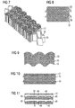
- the Fig. 7 shows a brush seal according to the invention, wherein the film 30, 32 has a structure for supporting the bristles 12.
- the perspective view of the brush seal according to Fig. 7 shows a triangular structure of the film 30, 32nd In the Fig. 8 is the triangular structure shown from below.
- the Fig. 9 and the Fig. 10 show a sinusoidal or a U-shaped structure of the film 30, 32.
- the film 30, 32 according to Fig. 11 is improved by formed in the longitudinal direction of the bristles webs 40, wherein the stiffness of the film 30, 32 is increased.
- a further embodiment of a brush seal 10 according to the invention is shown, which in terms of bristles 12, a wire 22 and a shell 24 as in Fig. 4 illustrated embodiment of the prior art is designed. Between the laid around the wire 22 bristles 12 is in accordance with the embodiment Fig. 6 However, further, a film 30, so that in the region of the protruding from the shell 24 bristles turn the in Fig. 5 Below, in perspective, illustrates layering of bristles 12 and sheets 30 and 32, respectively.
Landscapes
- Engineering & Computer Science (AREA)
- General Engineering & Computer Science (AREA)
- Mechanical Engineering (AREA)
- Sealing Devices (AREA)
- Turbine Rotor Nozzle Sealing (AREA)
- Brushes (AREA)
- Structures Of Non-Positive Displacement Pumps (AREA)
Description
- Die Erfindung betrifft eine Bürstendichtung für eine Strömungsmaschine zum Abdichten eines Spaltes zwischen einem rotierenden und einem stehenden Bauteil der Strömungsmaschine, bei der elastisch biegsame Borsten in mehreren, nebeneinander angeordneten Borstenreihen vorgesehen sind.
- In Strömungsmaschinen mit rotierenden und stehenden Bauteilen werden Dichtelemente unterschiedlicher Bauart zur Abdichtung verschiedener Druckräume verwendet. Hierbei kommen zwischen den rotierenden und den stehenden Bauteilen insbesondere berührungslose Dichtungen (z. B. Labyrinthdichtungen) oder nachgiebige berührende Dichtelemente zum Einsatz. Zu nachgiebigen berührenden Dichtelementen werden unter anderem so genannte Bürstendichtungen gezählt, bei denen Borsten zur Abdichtung zwischen Räumen mit unterschiedlichen Drücken verwendet werden.
- Während berührungslose Dichtungen zum Abdichten von Druckdifferenzen von einigen Millibar bis zu mehreren hundert bar geeignet sind, ist der Verwendungsbereich von Bürstendichtungen selbst bei mehrstufiger Anordnung (mehrere Bürstendichtungen hintereinander) aufgrund des "Blow-Over-Effektes" und eines "Auffächerns" in Bezug auf die maximale Druckdifferenz begrenzt.
- Der "Blow-Over-Effekt" ist in
Fig. 1 durch eine Querschnittsdarstellung einer Bürstendichtung 10 gemäß dem Stand der Technik veranschaulicht. Bei dieser Bürstendichtung 10 sind Borsten 12 in mehreren Reihen angeordnet und in einem Grundkörper 14 befestigt. Der Grundkörper 14 ist an zwei gegenüberliegenden Seiten von je einem Führungsblech 16 eingefasst, von denen das inFig. 1 rechts dargestellte Führungsblech 16 derart weit an den unteren Endbereich der Borsten 12 reicht, dass es die Borsten 12 dort abstützt. Bei einer entsprechend hohen Druckdifferenz "p1 » p2"an der Bürstendichtung 10 werden die Borsten 12 an diesem unteren Endbereich jedoch derart stark gebogen, dass Medium von dem inFig. 1 linksseitigen Druckraum in den rechtsseitigen Druckraum überströmen kann. - In
Fig. 2 ist das "Auffächern" einer Bürstendichtung 10 an einer Querschnittsdarstellung entsprechend der vonFig. 1 veranschaulicht. Beim "Auffächern" kommt es aufgrund einer ungünstigen Anströmung des unteren Endbereiches der Borsten 12 dazu, dass einzelne Borsten zum linksseitigen Druckraum hin aufbogen werden, sodass wiederum Medium aus diesem unter einem Druck p1 stehenden Druckraum in den rechtsseitigen, unter einem niedrigeren Druck p2 stehenden Druckraum gelangen kann. - Um die Leistungsfähigkeit bekannter Bürstendichtungen zu steigern, werden bei bisherigen Lösungen die einzelnen Borsten vergleichsweise dick ausgeführt, die einzelnen Borstenpakete durch ein Führungsblech bzw. einen Stützring gehalten (siehe
Fig. 1 und 2 , das rechte Führungsblech 16) und/oder das einzelne Borstenpaket insgesamt relativ breit bzw. dick ausgeführt. - Trotzdem sind der ertragbaren Druckdifferenz bekannter Bürstendichtungen weiterhin die oben genannten Grenzen gesetzt. Insbesondere können aufgrund des notwendigen Radialspiels zwischen den rotierenden und stehenden Bauteilen die Borsten mit einem Führungsblech bzw. einem Stützring nicht beliebig nah an einem gegenüberliegenden Bauteil abgestützt werden.
- Eine aus
EP 992721 US5106104 bekannte - Bürstendichtung für eine Strömungsmaschine zum Abdichten eines Spaltes zwischen einem rotierenden und einem stehenden Bauteil der Strömungsmaschine weist die eingangs genannten elastisch biegsamen Borsten in mehreren, nebeneinander angeordneten Borstenreihen auf, wobei die erfindungsgemäße Bürstendichtung einstufig ausgebildet ist. Zwischen mindestens zwei Borstenreihen ist darüber hinaus eine Folie oder eine Scheibe bzw. Membran angeordnet, welche sich in Längsrichtung der Borsten erstreckt.
- Es ist Aufgabe der vorliegenden Erfindung, eine Bürstendichtung der eingangs genannten Art dahingehend zu verbessern, dass bei einer damit ausgerüsteten Strömungsmaschine höhere Druckdifferenzen abgedichtet werden können.
- Die Aufgabe ist erfindungsgemäß mit einer Bürstendichtung gemäß Anspruch 1 und einer Strömungsmaschine gemäß Anspruch 13. gelöst. Vorteilhafte Weiterbildungen der Erfindung sind in den abhängigen Ansprüchen definiert.
- Die erfindungsgemäße Folie oder Scheibe besteht aus einem Material mit abrasiven Eigenschaften. So kann die Folie oder die Scheibe genau so lang wie die Borsten sein, wodurch die Steifigkeit der Borstenspitzen vergrößert wird und dadurch ein Umknicken der Borsten um die Kante des Führungsblechs stark vermindert wird.
- Eine einstufige Bürstendichtung zeichnet sich dadurch aus, dass mehrere Borsten im Wesentlichen berührend über ihre Länge angeordnet sind und dadurch ein Borstenpaket gebildet wird. Somit zeichnet sich eine einstufige Bürstendichtung durch ein mehrere eng beieinander liegenden Borsten umfassendes Borstenpaket aus.
Ein weiteres Merkmal einer einstufigen Bürstendichtung ist die Befestigung der Borsten in einem Bürstendichtungshalter, wobei die im Bürstendichtungshalter angeordneten Borstenenden eng beieinander liegen.
Mehrstufige Bürstendichtungen zeichnen sich durch zumindest zwei räumlich getrennte und hintereinander angeordnete Borstenpakete aus, wobei die jeweiligen Borstenpakete sich in der Regel nicht berühren. - Die Bürstendichtung gemäß der Erfindung weist also zwischen den einzelnen Borstenreihen seiner Borstenpakete mindestens eine Zwischenlage in Form einer Folie oder einer Scheibe auf. Die Scheibe kann dabei insbesondere ein dünnes Blech sein. Mit den derartigen erfindungsgemäßen Folien bzw. Scheiben wird erreicht, dass sich die einzelnen Borsten und erfindungsgemäßen Zwischenlagen gegenseitig stützen. Die Gefahr eines Umknickens von Borsten um die Kante eines Führungsbleches (siehe
Fig. 1 ) oder eines Auffächerns von Borsten (sieheFig. 2 ) ist erfindungsgemäß stark vermindert. Auf diese Weise ist die erfindungsgemäße Bürstendichtung auch für höhere Druckdifferenzen geeignet. Das Auffächern einzelner Borsten durch eine drallbehaftete Anströmung einer Bürstendichtung kann mit den erfindungsgemäßen Folien oder Scheiben insbesondere einströmseitig vermindert werden. - Um die erfindungsgemäße Folie oder Scheibe an der Büstendichtung kostengünstig anbringen und dauerhaft haltern zu können, ist es bevorzugt die Borsten mit einem Endbereich an einem Grundkörper ortsfest anzubringen und die Folie oder die Scheibe mit einem Randbereich ebenfalls mittels diesem Grundkörper zwischen den Borsten zu halten.
- Die Folie oder die Scheibe ist hierbei vorteilhafterweise aus einer Metall-Matrix oder aus Graphit hergestellt.
- Die erfindungsgemäße Folie oder Scheibe ist bevorzugt aus Kunststoff und/oder Metall hergestellt. Mit derartigen Materialen können die gewünschten Stützeffekte je nach erforderlicher Betriebstemperatur der Bürstendichtung kostengünstig erzielt werden.
- Darüber hinaus ist es erfindungsgemäß bevorzugt die Folie oder die Scheibe zumindest abschnittsweise perforiert und/oder zumindest abschnittsweise geschlitzt zu gestalten. Mit derartigen Bürstendichtungen kann der "Blow-Down-Effekt" der Bürstendichtung (d.h. das Schließen der Bürstendichtung durch radiale Druckkräfte auf das zugehörige Borstenpaket) aufrechterhalten werden.
- Schließlich ist es erfindungsgemäß bevorzugt, die Folie oder die Scheibe hinsichtlich der Längserstreckung der Borsten genauso lang wie diese und/oder kürzer als diese zu gestalten. Ferner lässt sich die erfindungsgemäße Packung von Borsten mit zugehöriger Folie oder Scheibe beliebig oft stapeln und beliebig dick ausführen. Die Anzahl von Folien oder Scheiben sowie deren einzelnen Dicke kann je nach Anforderung an die Dichtsituation variiert werden. Die Folien oder Scheiben können zusammen mit den zugehörigen Borsten vergossen, eingespritzt, verschweißt, gewickelt und/oder geklemmt ausgeführt werden.
- Bevorzugt weist die Folie oder die Scheibe eine Struktur zum Stützen der Borsten auf. Durch diese vergleichsweise leicht herstellbare Maßnahme kann die Steifigkeit des Blechs weiter erhöht werden. Dabei wird die Folie oder die Scheibe in ihrer Längsrichtung im Wesentlichen geknickt, um damit ein Verbiegen zu vermeiden.
Vorteilhafterweise wird die Folie oder die Scheibe sinusförmig, U-förmig oder dreieckförmig gewellt ausgebildet. - Nachfolgend wird ein Ausführungsbeispiel einer erfindungsgemäßen Bürstendichtung anhand der beigefügten schematischen Zeichnungen näher erläutert.
-
- Fig. 1
- einen Querschnitt einer Bürstendichtung gemäß dem Stand der Technik zur obigen Erläuterung des "Blow-Over-Effektes",
- Fig. 2
- einen Querschnitt einer Bürstendichtung gemäß dem Stand der Technik zur obigen Erläuterung des "Auf-fächerns",
- Fig. 3
- einen Querschnitt und darunter eine teilweise perspektivische Ansicht eines Ausführungsbeispiels einer Bürstendichtung gemäß dem Stand der Technik, welches jenem der
Fig. 1 und 2 entspricht, - Fig. 4
- einen Querschnitt eines weiteren Ausführungsbeispiels einer Bürstendichtung gemäß dem Stand der Technik,
- Fig. 5
- einen Querschnitt und darunter eine teilweise perspektivische Ansicht eines Ausführungsbeispiels einer erfindungsgemäßen Bürstendichtung, welche auf einer Bürstendichtung gemäß
Fig. 3 basiert, - Fig. 6
- einen Querschnitt eines weiteren Ausführungsbeispiels einer erfindungsgemäßen Bürstendichtung, welche auf einer Bürstendichtung gemäß
Fig. 4 basiert, - Fig. 7
- eine teilweise perspektivische Ansicht eines Ausführungsbeispiels einer erfindungsgemäßen Bürstendichtung mit einer gewellten Struktur der Scheibe,
- Fig. 8
- eine Ansicht von unten in Längsrichtung der Borsten gesehen eines Ausführungsbeispiels einer erfindungsgemäßen Bürstendichtung,
- Fig. 9
- eine Ansicht von unten in Längsrichtung der Borsten gesehen eines Ausführungsbeispiel einer erfindungsgemäßen Bürstendichtung,
- Fig. 10
- eine Ansicht von unten in Längsrichtung der Borsten gesehen eines Ausführungsbeispiels einer erfindungsgemäßen Bürstendichtung,
- Fig. 11
- eine Ansicht von unten in Längsrichtung der Borsten gesehen eines Ausführungsbeispiels einer erfindungsgemäßen Bürstendichtung.
- In
Fig. 3 ist eine Bürstendichtung 10 des Standes der Technik veranschaulicht, welche sich im Wesentlichen parallel erstreckende Borsten 12 aufweist, die zusammen ein Borstenpaket bilden. Die Borsten 12 sind in einen Grundkörper 14 eingegossen, der sich zwischen zwei Führungsblechen 16 befindet. Die Führungsbleche 16 erstrecken sich einzeln in Längsrichtung der Borsten 12, wobei das bezogen aufFig. 3 rechtsseitige Führungsblech 16 mit seinem unteren Endbereich in Richtung zu den Borsten 12 gekrümmt ist und die Borsten 12 an deren unteren Endbereich abstützt. Beim Rotieren der derartigen Bürstendichtung 10 in Richtung eines Pfeils 18 erfahren die bezogen aufFig. 3 unteren Endbereiche der Borsten 12 einen Reibungswiderstand an einem (in denFig. 3 bis 6 jeweils nicht dargestellten) gegenüberliegenden stehenden Bauteil, und die Borsten 12 werden dadurch entgegen ihrer Hauptbewegungsrichtung um einen Winkel 20 gekrümmt. - In
Fig. 4 ist ein Ausführungsbeispiel einer Bürstendichtung 10 gemäß dem Stand der Technik veranschaulicht, bei dem Borsten 12 um einen zentralen Draht 22 gelegt und außenseitig von einer im Querschnitt im wesentlichen kreisförmigen Schale 24 umfasst sind. Die Borsten 12 ragen aus dieser Schale 24 bezogen aufFig. 4 nach unten in Richtung auf ein (nicht dargestelltes) stehendes Bauteil heraus. - In
Fig. 5 ist ein Ausführungsbeispiel einer Bürstendichtung 10 gemäß der Erfindung veranschaulicht, welche ebenfalls Borsten 12, einen Grundkörper 14 sowie zwei Führungsbleche 16 aufweist. Die Bürstendichtung 10 rotiert ebenfalls in Richtung eines Pfeils 18. Die Borsten 12 sind dabei im wesentlich parallel zueinander in Borstenreihen 28 angeordnet und zwischen diesen Borstenreihen 28 befinden sich insgesamt zwei Folien 30 und 32. Die dabei einem Druckraum 34 mit vergleichsweise niedrigem Druck zugewandte Folie 30 ist in ihrer Folienfläche geschlossen ausgebildet. Hingegen ist die Folie 32, welche einen Druckraum 36 mit vergleichsweise hohem Druck zugewandt ist, mittels Öffnungen 38 perforiert ausgestaltet. - Die
Fig. 5 zeigt eine einstufige Bürstendichtung 10. Die zwei Folien 30 und 32 sind aus einem Material mit abrasiven Eigenschaften hergestellt. Als abrasives Material kann hierbei eine Metall-Matrix oder Graphit dienen. - Die
Fig. 7 zeigt eine erfindungsgemäße Bürstendichtung, wobei die Folie 30, 32 eine Struktur zum Stützen der Borsten 12 aufweist. Die perspektivische Darstellung der Bürstendichtung gemäßFig. 7 zeigt eine dreieckförmige Struktur der Folie 30, 32.
In derFig. 8 ist die dreieckförmige Struktur von unten gezeigt.
DieFig. 9 und dieFig. 10 zeigen eine sinusförmige bzw. eine U-förmige Struktur der Folie 30, 32. Die Folie 30, 32 gemäßFig. 11 wird durch in Längsrichtung der Borsten ausgebildete Stege 40 verbessert, wobei die Steifigkeit der Folie 30, 32 erhöht wird. - In
Fig. 6 ist ein weiteres Ausführungsbeispiel einer erfindungsgemäßen Bürstendichtung 10 dargestellt, welches hinsichtlich Borsten 12, einem Draht 22 und einer Schale 24 wie das inFig. 4 dargestellte Ausführungsbeispiel des Standes der Technik gestaltet ist. Zwischen den um den Draht 22 gelegten Borsten 12 befindet sich bei dem Ausführungsbeispiel gemäßFig. 6 jedoch ferner eine Folie 30, sodass sich im Bereich der aus der Schale 24 herausragenden Borsten wiederum die inFig. 5 unten perspektivisch veranschaulichte Schichtung von Borsten 12 und Folie/n 30 bzw. 32 ergibt.
Claims (13)
- Einstufige Bürstendichtung (10) für eine Strömungsmaschine zum Abdichten eines Spaltes zwischen einem rotierenden und einem stehenden Bauteil der Strömungsmaschine, bei der elastisch biegsame Borsten (12) in mehreren, nebeneinander angeordneten Borstenreihen (28) vorgesehen sind, wobei zwischen mindestens zwei Borstenreihen (28) eine Folie (30, 32) oder eine Scheibe angeordnet ist, welche sich in Längsrichtung der Borsten (12) erstreckt,
dadurch gekennzeichnet, dass
die Folie (30, 32) oder die Scheibe aus einem Material mit abrasiven Eigenschaften besteht. - Bürstendichtung nach Anspruch 1,
dadurch gekennzeichnet, dass
die Borsten (12) mit einem Endbereich an einem Grundkörper (14) ortsfest angebracht sind und die Folie (30, 32) oder die Scheibe mit einem Randbereich ebenfalls mit diesem Grundkörper (14) zwischen den Borsten (12) gehalten ist. - Bürstendichtung nach Anspruch 1,
wobei die Folie (30, 32) oder die Scheibe aus einer Metall-Matrix oder aus Graphit hergestellt ist. - Bürstendichtung nach Anspruch 1 oder 2,
dadurch gekennzeichnet; dass
die Folie (30, 32) oder die Scheibe aus Kunststoff hergestellt ist. - Bürstendichtung nach Anspruch 1 oder 2,
dadurch gekennzeichnet, dass
die Folie (30, 32) oder die Scheibe aus Metall hergestellt ist. - Bürstendichtung nach einem der vorhergehenden Ansprüche,
dadurch gekennzeichnet; dass
die Folie (30, 32) oder die Scheibe zumindest abschnittsweise perforiert gestaltet ist. - Bürstendichtung nach einem der vorhergehenden Ansprüche,
dadurch gekennzeichnet, dass
die Folie (30, 32) oder die Scheibe zumindest abschnittsweise geschlitzt gestaltet ist. - Bürstendichtung nach einem der vorhergehenden Ansprüche,
dadurch gekennzeichnet, dass
die Folie (30, 32) oder die Scheibe hinsichtlich der Längserstreckung der Borsten (12) genauso lang wie diese gestaltet ist. - Bürstendichtung nach einem der vorhergehenden Ansprüche,
dadurch gekennzeichnet, dass
die Folie (30, 32) oder die Scheibe hinsichtlich der Längserstreckung der Borsten (12) kürzer als diese gestaltet ist. - Bürstendichtung nach einem der vorhergehenden Ansprüche,
wobei die Folie (30, 32) oder die Scheibe eine Struktur zum Stützen der Borsten aufweist. - Bürstendichtung nach Anspruch 10,
wobei die Folie (30, 32) oder die Scheibe gewellt ist. - Bürstendichtung nach Anspruch 11,
wobei die Folie (30, 32) oder die Scheibe sinusförmig, U-förmig oder dreieckförmig gewellt ist. - Strömungsmaschine mit einer Bürstendichtung (10) nach einem der Ansprüche 1 bis 7.
Priority Applications (2)
| Application Number | Priority Date | Filing Date | Title |
|---|---|---|---|
| EP07802585A EP2052171B1 (de) | 2006-08-18 | 2007-08-13 | Bürstendichtung für eine Strömungsmaschine und Strömungsmaschine mit einer solchen Bürstendichtung |
| PL07802585T PL2052171T3 (pl) | 2006-08-18 | 2007-08-13 | Uszczelnienie szczotkowe do maszyny przepływowej i maszyna przepływowa z takim uszczelnieniem szczotkowym |
Applications Claiming Priority (3)
| Application Number | Priority Date | Filing Date | Title |
|---|---|---|---|
| EP06017253A EP1892442A1 (de) | 2006-08-18 | 2006-08-18 | Bürstendichtung für eine Strömungsmaschine |
| PCT/EP2007/058353 WO2008020002A1 (de) | 2006-08-18 | 2007-08-13 | Bürstendichtung für eine strömungsmaschine |
| EP07802585A EP2052171B1 (de) | 2006-08-18 | 2007-08-13 | Bürstendichtung für eine Strömungsmaschine und Strömungsmaschine mit einer solchen Bürstendichtung |
Publications (2)
| Publication Number | Publication Date |
|---|---|
| EP2052171A1 EP2052171A1 (de) | 2009-04-29 |
| EP2052171B1 true EP2052171B1 (de) | 2009-10-14 |
Family
ID=37496631
Family Applications (2)
| Application Number | Title | Priority Date | Filing Date |
|---|---|---|---|
| EP06017253A Ceased EP1892442A1 (de) | 2006-08-18 | 2006-08-18 | Bürstendichtung für eine Strömungsmaschine |
| EP07802585A Not-in-force EP2052171B1 (de) | 2006-08-18 | 2007-08-13 | Bürstendichtung für eine Strömungsmaschine und Strömungsmaschine mit einer solchen Bürstendichtung |
Family Applications Before (1)
| Application Number | Title | Priority Date | Filing Date |
|---|---|---|---|
| EP06017253A Ceased EP1892442A1 (de) | 2006-08-18 | 2006-08-18 | Bürstendichtung für eine Strömungsmaschine |
Country Status (9)
| Country | Link |
|---|---|
| US (1) | US8459652B2 (de) |
| EP (2) | EP1892442A1 (de) |
| JP (1) | JP5100752B2 (de) |
| CN (1) | CN101506553B (de) |
| AT (1) | ATE445797T1 (de) |
| DE (1) | DE502007001759D1 (de) |
| ES (1) | ES2335945T3 (de) |
| PL (1) | PL2052171T3 (de) |
| WO (1) | WO2008020002A1 (de) |
Families Citing this family (39)
| Publication number | Priority date | Publication date | Assignee | Title |
|---|---|---|---|---|
| US8393049B2 (en) * | 2005-12-12 | 2013-03-12 | Triverus, Llc | Surface cleaning and recycling apparatus and method |
| DE102008006485A1 (de) * | 2008-01-29 | 2009-07-30 | Mtu Aero Engines Gmbh | Bürstendichtung und Verfahren zur Montage einer Bürstendichtung |
| DE102008006486A1 (de) * | 2008-01-29 | 2009-07-30 | Mtu Aero Engines Gmbh | Bürstendichtung und Verfahren zur Montage einer Bürstendichtung |
| DE102008060371A1 (de) * | 2008-12-03 | 2010-06-10 | Mtu Aero Engines Gmbh | Bürstendichtung |
| US20100164177A1 (en) * | 2008-12-30 | 2010-07-01 | Eaton Corporation | Hybrid multistage brush seal |
| US8505923B2 (en) * | 2009-08-31 | 2013-08-13 | Sealeze, A Unit of Jason, Inc. | Brush seal with stress and deflection accommodating membrane |
| US8596973B2 (en) * | 2009-12-07 | 2013-12-03 | Cmg Tech, Llc | Leaf seal assembly including polymer member and rotary machine containing such seal assembly |
| US8690527B2 (en) * | 2010-06-30 | 2014-04-08 | Honeywell International Inc. | Flow discouraging systems and gas turbine engines |
| US8523515B2 (en) | 2010-11-15 | 2013-09-03 | General Electric Company | Noise reducer for rotor blade in wind turbine |
| WO2012082805A2 (en) * | 2010-12-13 | 2012-06-21 | Sealeze A Unit Of Jason, Inc. | High temperature device shaft brush seal assembly, brush seal, and mounting arrangement |
| US8794918B2 (en) | 2011-01-07 | 2014-08-05 | General Electric Company | System for adjusting brush seal segments in turbomachine |
| US9121297B2 (en) | 2011-03-28 | 2015-09-01 | General Electric Company | Rotating brush seal |
| US9255486B2 (en) | 2011-03-28 | 2016-02-09 | General Electric Company | Rotating brush seal |
| EP2505881A1 (de) | 2011-03-30 | 2012-10-03 | Siemens Aktiengesellschaft | Bürstendichtung für hohe Druckdifferenzen |
| US8414261B2 (en) | 2011-05-31 | 2013-04-09 | General Electric Company | Noise reducer for rotor blade in wind turbine |
| US9528384B2 (en) * | 2011-06-27 | 2016-12-27 | General Electric Company | Brush seal |
| US20120326393A1 (en) * | 2011-06-27 | 2012-12-27 | General Electric Company | Brush seal |
| US8834127B2 (en) | 2011-09-09 | 2014-09-16 | General Electric Company | Extension for rotor blade in wind turbine |
| US8430638B2 (en) * | 2011-12-19 | 2013-04-30 | General Electric Company | Noise reducer for rotor blade in wind turbine |
| WO2013153868A1 (ja) * | 2012-04-08 | 2013-10-17 | イーグル工業株式会社 | ブラシシール |
| CN102900476B (zh) * | 2012-09-21 | 2014-11-26 | 清华大学 | 一种利用压电效应的低泄漏刷式密封结构 |
| CN103104297B (zh) * | 2013-02-05 | 2015-07-08 | 江苏透平密封高科技股份有限公司 | 一种刷式密封 |
| US9610670B2 (en) * | 2013-06-07 | 2017-04-04 | Apple Inc. | Consumable abrasive tool for creating shiny chamfer |
| CN103406739A (zh) * | 2013-08-20 | 2013-11-27 | 田波 | 一种新型刷式密封制造方法 |
| DE102013217581A1 (de) | 2013-09-04 | 2015-03-05 | MTU Aero Engines AG | Dichtungsanordnung in einer axialen Strömungsmaschine |
| DE102013220168B4 (de) * | 2013-10-07 | 2015-08-27 | MTU Aero Engines AG | Bürstendichtungssystem zum Abdichten eines Spalts zwischen relativ zueinander bewegbaren Bauteilen einer thermischen Gasturbine |
| US9494134B2 (en) | 2013-11-20 | 2016-11-15 | General Electric Company | Noise reducing extension plate for rotor blade in wind turbine |
| US9587505B2 (en) | 2013-12-05 | 2017-03-07 | General Electric Company | L brush seal for turbomachinery application |
| US9322287B2 (en) | 2014-06-03 | 2016-04-26 | General Electric Company | Brush seal for turbine |
| CN104047640B (zh) * | 2014-06-10 | 2015-11-18 | 清华大学 | 一种可调径向间隙的刷式密封结构 |
| CN104089018B (zh) * | 2014-06-26 | 2016-10-12 | 南京博沃科技发展有限公司 | 一种刷丝受约束的刷式密封 |
| CN107208801B (zh) * | 2015-03-09 | 2020-03-13 | 伊格尔工业股份有限公司 | 分割型刷式密封装置、刷式密封片和分割型刷式密封装置的组装方法 |
| US10180125B2 (en) | 2015-04-20 | 2019-01-15 | General Electric Company | Airflow configuration for a wind turbine rotor blade |
| DE102015219946A1 (de) * | 2015-10-14 | 2017-04-20 | Siemens Aktiengesellschaft | Bürstendichtung sowie Turbomaschine mit Bürstendichtung |
| DE102016208145A1 (de) * | 2016-05-11 | 2017-11-16 | Elringklinger Ag | Dichtungsvorrichtung |
| US10465652B2 (en) | 2017-01-26 | 2019-11-05 | General Electric Company | Vortex generators for wind turbine rotor blades having noise-reducing features |
| CN108223798B (zh) * | 2017-12-26 | 2020-01-14 | 中国航发四川燃气涡轮研究院 | 一种带芯部镂空指尖片的指尖密封装置 |
| US10767623B2 (en) | 2018-04-13 | 2020-09-08 | General Electric Company | Serrated noise reducer for a wind turbine rotor blade |
| US10746157B2 (en) | 2018-08-31 | 2020-08-18 | General Electric Company | Noise reducer for a wind turbine rotor blade having a cambered serration |
Family Cites Families (10)
| Publication number | Priority date | Publication date | Assignee | Title |
|---|---|---|---|---|
| US885032A (en) * | 1907-06-24 | 1908-04-21 | Sebastian Ziani De Ferranti | Fluid packing. |
| US3745053A (en) * | 1972-05-26 | 1973-07-10 | Usm Corp | Weatherstrip |
| DE3215334C1 (de) * | 1982-04-24 | 1983-06-09 | Dr. Johannes Heidenhain Gmbh, 8225 Traunreut | Gekapselte Messeinrichtung |
| US5106104A (en) * | 1990-10-11 | 1992-04-21 | General Electric Company | Constant pressure drop multiple stage brush seal |
| US5201530A (en) * | 1991-10-18 | 1993-04-13 | United Technologies Corporation | Multi-layered brush seal |
| US6808179B1 (en) * | 1998-07-31 | 2004-10-26 | Concepts Eti, Inc. | Turbomachinery seal |
| GB9821927D0 (en) * | 1998-10-08 | 1998-12-02 | Rolls Royce Plc | Improved brush seal |
| GB2355049A (en) * | 1999-10-05 | 2001-04-11 | Rolls Royce Plc | Differential lay brush seal |
| US7052015B2 (en) * | 2002-08-06 | 2006-05-30 | United Technologies Corporation | Cooling arrangement for brush seal |
| CN100379948C (zh) * | 2003-09-05 | 2008-04-09 | 通用电气公司 | 刷式密封装置的支撑 |
-
2006
- 2006-08-18 EP EP06017253A patent/EP1892442A1/de not_active Ceased
-
2007
- 2007-08-13 DE DE502007001759T patent/DE502007001759D1/de active Active
- 2007-08-13 CN CN2007800306250A patent/CN101506553B/zh not_active Expired - Fee Related
- 2007-08-13 US US12/310,218 patent/US8459652B2/en not_active Expired - Fee Related
- 2007-08-13 EP EP07802585A patent/EP2052171B1/de not_active Not-in-force
- 2007-08-13 ES ES07802585T patent/ES2335945T3/es active Active
- 2007-08-13 WO PCT/EP2007/058353 patent/WO2008020002A1/de not_active Ceased
- 2007-08-13 PL PL07802585T patent/PL2052171T3/pl unknown
- 2007-08-13 JP JP2009525016A patent/JP5100752B2/ja not_active Expired - Fee Related
- 2007-08-13 AT AT07802585T patent/ATE445797T1/de active
Also Published As
| Publication number | Publication date |
|---|---|
| EP1892442A1 (de) | 2008-02-27 |
| PL2052171T3 (pl) | 2010-03-31 |
| US20100068042A1 (en) | 2010-03-18 |
| WO2008020002A1 (de) | 2008-02-21 |
| CN101506553B (zh) | 2012-06-20 |
| DE502007001759D1 (de) | 2009-11-26 |
| US8459652B2 (en) | 2013-06-11 |
| ATE445797T1 (de) | 2009-10-15 |
| EP2052171A1 (de) | 2009-04-29 |
| ES2335945T3 (es) | 2010-04-06 |
| JP2010500916A (ja) | 2010-01-14 |
| JP5100752B2 (ja) | 2012-12-19 |
| CN101506553A (zh) | 2009-08-12 |
Similar Documents
| Publication | Publication Date | Title |
|---|---|---|
| WO2008020002A1 (de) | Bürstendichtung für eine strömungsmaschine | |
| EP2304193B1 (de) | Dichtung zum eindämmen von leckströmungen zwischen benachbarten bauteilen von strömungsmaschinen, insbesondere gasturbinen | |
| EP0483256B1 (de) | Wabenkörper mit internen strömungsleitflächen, insbesondere katalysatorkörper für kraftfahrzeuge | |
| EP1825174B1 (de) | Lamellendichtung, insbesondere für eine gasturbine | |
| DE602004012920T2 (de) | Lamellenbürstendichtung | |
| EP3583336B1 (de) | Dichtungsanordnung mit optimiertem schmierverhalten | |
| WO2001083951A1 (de) | Anordnung zur dichtung eines spaltes | |
| DE10296563T5 (de) | Rotationsmaschine mit Dichtungsvorrichtung | |
| DE4403605C2 (de) | Spaltdichtung zwischen zwei gegeneinander beweglichen Bauteilen | |
| WO2009000802A2 (de) | Leitschaufel für eine gasturbine | |
| EP3324002B1 (de) | Dichtungssystem für eine turbinenstufe und axiale strömungsmaschine | |
| EP2963318B1 (de) | Bürstendichtung | |
| EP3091188A1 (de) | Strömungsmaschine mit einer dichtungseinrichtung | |
| DE102013219300A1 (de) | Zwischenplatte und Steuereinheit | |
| DE2255626C3 (de) | Dichtung zwischen einer Drehspeicherwärmetauscherscheibe und ihrem Gehäuse, insbesondere bei einer Gasturbine | |
| EP1073827A1 (de) | Turbinenschaufel | |
| DE102005019250B3 (de) | Kammerungsring zum Schutz der Dichtzone von Stopfbuchspackungen | |
| EP3321583B1 (de) | Brennkammer einer gasturbine mit zumindest einer schindel | |
| DE102012222019A1 (de) | Plattenwärmeaustauscher in abgedichteter Bauweise | |
| EP1898050B1 (de) | Dämpfungs- und Dichtungssystem für Turbinenschaufeln | |
| EP1991762A1 (de) | Gasturbine mit ringförmigem hitzeschild und abgewinkelten dichtungsstreifen | |
| EP3472438A1 (de) | Dichtsegment für eine turbine, anordnung zur äusseren begrenzung eines strömungspfades einer turbine sowie stator-rotor-dichtung | |
| DE3741388C1 (de) | Filtervorrichtung | |
| EP0619447A1 (de) | Metallische Flachdichtung | |
| DE102010015371A1 (de) | Vorrichtung zur Verteilung von Fluidmedien in Wabenkanäle |
Legal Events
| Date | Code | Title | Description |
|---|---|---|---|
| PUAI | Public reference made under article 153(3) epc to a published international application that has entered the european phase |
Free format text: ORIGINAL CODE: 0009012 |
|
| GRAP | Despatch of communication of intention to grant a patent |
Free format text: ORIGINAL CODE: EPIDOSNIGR1 |
|
| 17P | Request for examination filed |
Effective date: 20090115 |
|
| AK | Designated contracting states |
Kind code of ref document: A1 Designated state(s): AT BE BG CH CY CZ DE DK EE ES FI FR GB GR HU IE IS IT LI LT LU LV MC MT NL PL PT RO SE SI SK TR |
|
| AX | Request for extension of the european patent |
Extension state: AL BA HR MK RS |
|
| RTI1 | Title (correction) |
Free format text: BRUSH SEAL FOR A TURBOMACHINE, AND TURBOMACHINE WITH SUCH A BRUSH SEAL |
|
| DAX | Request for extension of the european patent (deleted) | ||
| GRAS | Grant fee paid |
Free format text: ORIGINAL CODE: EPIDOSNIGR3 |
|
| GRAA | (expected) grant |
Free format text: ORIGINAL CODE: 0009210 |
|
| AK | Designated contracting states |
Kind code of ref document: B1 Designated state(s): AT BE BG CH CY CZ DE DK EE ES FI FR GB GR HU IE IS IT LI LT LU LV MC MT NL PL PT RO SE SI SK TR |
|
| REG | Reference to a national code |
Ref country code: GB Ref legal event code: FG4D Free format text: NOT ENGLISH |
|
| REG | Reference to a national code |
Ref country code: CH Ref legal event code: NV Representative=s name: SIEMENS SCHWEIZ AG Ref country code: CH Ref legal event code: EP |
|
| REG | Reference to a national code |
Ref country code: IE Ref legal event code: FG4D |
|
| REF | Corresponds to: |
Ref document number: 502007001759 Country of ref document: DE Date of ref document: 20091126 Kind code of ref document: P |
|
| LTIE | Lt: invalidation of european patent or patent extension |
Effective date: 20091014 |
|
| REG | Reference to a national code |
Ref country code: PL Ref legal event code: T3 |
|
| NLV1 | Nl: lapsed or annulled due to failure to fulfill the requirements of art. 29p and 29m of the patents act | ||
| REG | Reference to a national code |
Ref country code: ES Ref legal event code: FG2A Ref document number: 2335945 Country of ref document: ES Kind code of ref document: T3 |
|
| PG25 | Lapsed in a contracting state [announced via postgrant information from national office to epo] |
Ref country code: IS Free format text: LAPSE BECAUSE OF FAILURE TO SUBMIT A TRANSLATION OF THE DESCRIPTION OR TO PAY THE FEE WITHIN THE PRESCRIBED TIME-LIMIT Effective date: 20100214 Ref country code: FI Free format text: LAPSE BECAUSE OF FAILURE TO SUBMIT A TRANSLATION OF THE DESCRIPTION OR TO PAY THE FEE WITHIN THE PRESCRIBED TIME-LIMIT Effective date: 20091014 Ref country code: SE Free format text: LAPSE BECAUSE OF FAILURE TO SUBMIT A TRANSLATION OF THE DESCRIPTION OR TO PAY THE FEE WITHIN THE PRESCRIBED TIME-LIMIT Effective date: 20091014 Ref country code: LT Free format text: LAPSE BECAUSE OF FAILURE TO SUBMIT A TRANSLATION OF THE DESCRIPTION OR TO PAY THE FEE WITHIN THE PRESCRIBED TIME-LIMIT Effective date: 20091014 Ref country code: PT Free format text: LAPSE BECAUSE OF FAILURE TO SUBMIT A TRANSLATION OF THE DESCRIPTION OR TO PAY THE FEE WITHIN THE PRESCRIBED TIME-LIMIT Effective date: 20100215 |
|
| REG | Reference to a national code |
Ref country code: IE Ref legal event code: FD4D |
|
| PG25 | Lapsed in a contracting state [announced via postgrant information from national office to epo] |
Ref country code: LV Free format text: LAPSE BECAUSE OF FAILURE TO SUBMIT A TRANSLATION OF THE DESCRIPTION OR TO PAY THE FEE WITHIN THE PRESCRIBED TIME-LIMIT Effective date: 20091014 Ref country code: SI Free format text: LAPSE BECAUSE OF FAILURE TO SUBMIT A TRANSLATION OF THE DESCRIPTION OR TO PAY THE FEE WITHIN THE PRESCRIBED TIME-LIMIT Effective date: 20091014 |
|
| PG25 | Lapsed in a contracting state [announced via postgrant information from national office to epo] |
Ref country code: DK Free format text: LAPSE BECAUSE OF FAILURE TO SUBMIT A TRANSLATION OF THE DESCRIPTION OR TO PAY THE FEE WITHIN THE PRESCRIBED TIME-LIMIT Effective date: 20091014 Ref country code: BG Free format text: LAPSE BECAUSE OF FAILURE TO SUBMIT A TRANSLATION OF THE DESCRIPTION OR TO PAY THE FEE WITHIN THE PRESCRIBED TIME-LIMIT Effective date: 20100114 Ref country code: EE Free format text: LAPSE BECAUSE OF FAILURE TO SUBMIT A TRANSLATION OF THE DESCRIPTION OR TO PAY THE FEE WITHIN THE PRESCRIBED TIME-LIMIT Effective date: 20091014 Ref country code: RO Free format text: LAPSE BECAUSE OF FAILURE TO SUBMIT A TRANSLATION OF THE DESCRIPTION OR TO PAY THE FEE WITHIN THE PRESCRIBED TIME-LIMIT Effective date: 20091014 Ref country code: IE Free format text: LAPSE BECAUSE OF FAILURE TO SUBMIT A TRANSLATION OF THE DESCRIPTION OR TO PAY THE FEE WITHIN THE PRESCRIBED TIME-LIMIT Effective date: 20091014 |
|
| PLBE | No opposition filed within time limit |
Free format text: ORIGINAL CODE: 0009261 |
|
| STAA | Information on the status of an ep patent application or granted ep patent |
Free format text: STATUS: NO OPPOSITION FILED WITHIN TIME LIMIT |
|
| PG25 | Lapsed in a contracting state [announced via postgrant information from national office to epo] |
Ref country code: SK Free format text: LAPSE BECAUSE OF FAILURE TO SUBMIT A TRANSLATION OF THE DESCRIPTION OR TO PAY THE FEE WITHIN THE PRESCRIBED TIME-LIMIT Effective date: 20091014 Ref country code: CZ Free format text: LAPSE BECAUSE OF FAILURE TO SUBMIT A TRANSLATION OF THE DESCRIPTION OR TO PAY THE FEE WITHIN THE PRESCRIBED TIME-LIMIT Effective date: 20091014 |
|
| 26N | No opposition filed |
Effective date: 20100715 |
|
| PG25 | Lapsed in a contracting state [announced via postgrant information from national office to epo] |
Ref country code: GR Free format text: LAPSE BECAUSE OF FAILURE TO SUBMIT A TRANSLATION OF THE DESCRIPTION OR TO PAY THE FEE WITHIN THE PRESCRIBED TIME-LIMIT Effective date: 20100115 |
|
| BERE | Be: lapsed |
Owner name: SIEMENS A.G. Effective date: 20100831 |
|
| PG25 | Lapsed in a contracting state [announced via postgrant information from national office to epo] |
Ref country code: MC Free format text: LAPSE BECAUSE OF NON-PAYMENT OF DUE FEES Effective date: 20100831 |
|
| REG | Reference to a national code |
Ref country code: FR Ref legal event code: ST Effective date: 20110502 |
|
| PG25 | Lapsed in a contracting state [announced via postgrant information from national office to epo] |
Ref country code: FR Free format text: LAPSE BECAUSE OF NON-PAYMENT OF DUE FEES Effective date: 20100831 Ref country code: BE Free format text: LAPSE BECAUSE OF NON-PAYMENT OF DUE FEES Effective date: 20100831 |
|
| PG25 | Lapsed in a contracting state [announced via postgrant information from national office to epo] |
Ref country code: MT Free format text: LAPSE BECAUSE OF FAILURE TO SUBMIT A TRANSLATION OF THE DESCRIPTION OR TO PAY THE FEE WITHIN THE PRESCRIBED TIME-LIMIT Effective date: 20091014 |
|
| PG25 | Lapsed in a contracting state [announced via postgrant information from national office to epo] |
Ref country code: CY Free format text: LAPSE BECAUSE OF FAILURE TO SUBMIT A TRANSLATION OF THE DESCRIPTION OR TO PAY THE FEE WITHIN THE PRESCRIBED TIME-LIMIT Effective date: 20091014 |
|
| PG25 | Lapsed in a contracting state [announced via postgrant information from national office to epo] |
Ref country code: NL Free format text: LAPSE BECAUSE OF FAILURE TO SUBMIT A TRANSLATION OF THE DESCRIPTION OR TO PAY THE FEE WITHIN THE PRESCRIBED TIME-LIMIT Effective date: 20091014 Ref country code: LU Free format text: LAPSE BECAUSE OF NON-PAYMENT OF DUE FEES Effective date: 20100813 Ref country code: HU Free format text: LAPSE BECAUSE OF FAILURE TO SUBMIT A TRANSLATION OF THE DESCRIPTION OR TO PAY THE FEE WITHIN THE PRESCRIBED TIME-LIMIT Effective date: 20100415 |
|
| PG25 | Lapsed in a contracting state [announced via postgrant information from national office to epo] |
Ref country code: TR Free format text: LAPSE BECAUSE OF FAILURE TO SUBMIT A TRANSLATION OF THE DESCRIPTION OR TO PAY THE FEE WITHIN THE PRESCRIBED TIME-LIMIT Effective date: 20091014 |
|
| REG | Reference to a national code |
Ref country code: AT Ref legal event code: MM01 Ref document number: 445797 Country of ref document: AT Kind code of ref document: T Effective date: 20120831 |
|
| PG25 | Lapsed in a contracting state [announced via postgrant information from national office to epo] |
Ref country code: AT Free format text: LAPSE BECAUSE OF NON-PAYMENT OF DUE FEES Effective date: 20120831 |
|
| PGFP | Annual fee paid to national office [announced via postgrant information from national office to epo] |
Ref country code: CH Payment date: 20151102 Year of fee payment: 9 Ref country code: DE Payment date: 20151016 Year of fee payment: 9 |
|
| PGFP | Annual fee paid to national office [announced via postgrant information from national office to epo] |
Ref country code: GB Payment date: 20160811 Year of fee payment: 10 Ref country code: IT Payment date: 20160830 Year of fee payment: 10 |
|
| PGFP | Annual fee paid to national office [announced via postgrant information from national office to epo] |
Ref country code: PL Payment date: 20160725 Year of fee payment: 10 |
|
| PGFP | Annual fee paid to national office [announced via postgrant information from national office to epo] |
Ref country code: ES Payment date: 20160926 Year of fee payment: 10 |
|
| REG | Reference to a national code |
Ref country code: DE Ref legal event code: R119 Ref document number: 502007001759 Country of ref document: DE |
|
| REG | Reference to a national code |
Ref country code: CH Ref legal event code: PL |
|
| PG25 | Lapsed in a contracting state [announced via postgrant information from national office to epo] |
Ref country code: LI Free format text: LAPSE BECAUSE OF NON-PAYMENT OF DUE FEES Effective date: 20160831 Ref country code: CH Free format text: LAPSE BECAUSE OF NON-PAYMENT OF DUE FEES Effective date: 20160831 |
|
| PG25 | Lapsed in a contracting state [announced via postgrant information from national office to epo] |
Ref country code: DE Free format text: LAPSE BECAUSE OF NON-PAYMENT OF DUE FEES Effective date: 20170301 |
|
| GBPC | Gb: european patent ceased through non-payment of renewal fee |
Effective date: 20170813 |
|
| PG25 | Lapsed in a contracting state [announced via postgrant information from national office to epo] |
Ref country code: GB Free format text: LAPSE BECAUSE OF NON-PAYMENT OF DUE FEES Effective date: 20170813 |
|
| PG25 | Lapsed in a contracting state [announced via postgrant information from national office to epo] |
Ref country code: IT Free format text: LAPSE BECAUSE OF NON-PAYMENT OF DUE FEES Effective date: 20170813 |
|
| REG | Reference to a national code |
Ref country code: ES Ref legal event code: FD2A Effective date: 20181029 |
|
| PG25 | Lapsed in a contracting state [announced via postgrant information from national office to epo] |
Ref country code: PL Free format text: LAPSE BECAUSE OF NON-PAYMENT OF DUE FEES Effective date: 20170813 |
|
| PG25 | Lapsed in a contracting state [announced via postgrant information from national office to epo] |
Ref country code: ES Free format text: LAPSE BECAUSE OF NON-PAYMENT OF DUE FEES Effective date: 20170814 |