EP2051390A2 - Appareil de transmission radio - Google Patents
Appareil de transmission radio Download PDFInfo
- Publication number
- EP2051390A2 EP2051390A2 EP08163606A EP08163606A EP2051390A2 EP 2051390 A2 EP2051390 A2 EP 2051390A2 EP 08163606 A EP08163606 A EP 08163606A EP 08163606 A EP08163606 A EP 08163606A EP 2051390 A2 EP2051390 A2 EP 2051390A2
- Authority
- EP
- European Patent Office
- Prior art keywords
- distortion compensation
- compensation coefficient
- timing
- distortion
- transmission
- Prior art date
- Legal status (The legal status is an assumption and is not a legal conclusion. Google has not performed a legal analysis and makes no representation as to the accuracy of the status listed.)
- Withdrawn
Links
Images


Classifications
-
- H—ELECTRICITY
- H03—ELECTRONIC CIRCUITRY
- H03F—AMPLIFIERS
- H03F3/00—Amplifiers with only discharge tubes or only semiconductor devices as amplifying elements
- H03F3/20—Power amplifiers, e.g. Class B amplifiers, Class C amplifiers
- H03F3/24—Power amplifiers, e.g. Class B amplifiers, Class C amplifiers of transmitter output stages
-
- H—ELECTRICITY
- H03—ELECTRONIC CIRCUITRY
- H03F—AMPLIFIERS
- H03F1/00—Details of amplifiers with only discharge tubes, only semiconductor devices or only unspecified devices as amplifying elements
- H03F1/32—Modifications of amplifiers to reduce non-linear distortion
- H03F1/3241—Modifications of amplifiers to reduce non-linear distortion using predistortion circuits
- H03F1/3294—Acting on the real and imaginary components of the input signal
-
- H—ELECTRICITY
- H03—ELECTRONIC CIRCUITRY
- H03F—AMPLIFIERS
- H03F2200/00—Indexing scheme relating to amplifiers
- H03F2200/204—A hybrid coupler being used at the output of an amplifier circuit
-
- H—ELECTRICITY
- H03—ELECTRONIC CIRCUITRY
- H03F—AMPLIFIERS
- H03F2200/00—Indexing scheme relating to amplifiers
- H03F2200/207—A hybrid coupler being used as power measuring circuit at the output of an amplifier circuit
-
- H—ELECTRICITY
- H03—ELECTRONIC CIRCUITRY
- H03F—AMPLIFIERS
- H03F2200/00—Indexing scheme relating to amplifiers
- H03F2200/336—A I/Q, i.e. phase quadrature, modulator or demodulator being used in an amplifying circuit
-
- H—ELECTRICITY
- H03—ELECTRONIC CIRCUITRY
- H03F—AMPLIFIERS
- H03F2200/00—Indexing scheme relating to amplifiers
- H03F2200/451—Indexing scheme relating to amplifiers the amplifier being a radio frequency amplifier
-
- H—ELECTRICITY
- H03—ELECTRONIC CIRCUITRY
- H03F—AMPLIFIERS
- H03F2201/00—Indexing scheme relating to details of amplifiers with only discharge tubes, only semiconductor devices or only unspecified devices as amplifying elements covered by H03F1/00
- H03F2201/32—Indexing scheme relating to modifications of amplifiers to reduce non-linear distortion
- H03F2201/3233—Adaptive predistortion using lookup table, e.g. memory, RAM, ROM, LUT, to generate the predistortion
-
- H—ELECTRICITY
- H04—ELECTRIC COMMUNICATION TECHNIQUE
- H04B—TRANSMISSION
- H04B1/00—Details of transmission systems, not covered by a single one of groups H04B3/00 - H04B13/00; Details of transmission systems not characterised by the medium used for transmission
- H04B1/02—Transmitters
- H04B1/04—Circuits
- H04B2001/0408—Circuits with power amplifiers
- H04B2001/0425—Circuits with power amplifiers with linearisation using predistortion
Definitions
- the present invention relates to a radio transmission apparatus performing distortion compensation processing using a distortion compensation coefficient, and more particularly to a radio transmission apparatus performing distortion compensation processing upon a transmission signal, particularly but not exclusively in a time division duplex (TDD) transmission scheme.
- TDD time division duplex
- an amplifier having high linearity is required to suppress deterioration in a spectral characteristic and a transmission characteristic caused by signal distortion.
- a predistortion scheme is known.
- the principle of the predistortion scheme is to obtain a desired signal having no distortion in an amplifier output by adding beforehand an inverse characteristic of the amplifier distortion characteristic to an amplifier input signal.
- the predistortion scheme for example, detailed descriptions have been given in the following patent documents 1, 2, 3 and 4.
- a transmission signal before distortion compensation is compared with a demodulated feedback signal, and using the error thereof, a distortion compensation coefficient is calculated and updated.
- the distortion compensation coefficient is stored into a memory of which the address is determined by the amplitude or the power of the transmission signal, or the function thereof. Then, using the updated distortion compensation coefficient, predistortion is applied to a transmission signal which is to be transmitted next, and the processing result is output. By repeating the above process, finally, the result converges on an optimum distortion compensation coefficient. The distortion in the transmission power amplifier is compensated accordingly.
- the transmission level of the top symbol (preamble) of the transmission signal becomes approximately 3 dB greater than the transmission level of a data symbol period. This produces a narrower linear region. As a result, a larger error in the distortion compensation coefficient is produced, and thereby correct distortion compensation operation is impeded.
- the transmission period and the reception period are switched alternately.
- the distortion compensation coefficient is not updated during the reception period. If the distortion compensation coefficient is updated only during the transmission period, a longer time is required for the convergence of the distortion compensation coefficient, as compared to the case of the FDD scheme.
- the number of transmission subcarriers of the transmission signals of the WiMAX system varies symbol-by-symbol. This causes a fluctuated transmission power level in each symbol period.
- the transmission level is varied after the distortion compensation coefficient at a certain transmission level is calculated. This makes it difficult to obtain an optimal distortion compensation coefficient at all times. Therefore, it is necessary to shorten the convergence time of the distortion compensation coefficient, and to obtain a faster processing speed.
- a correct distortion compensation coefficient cannot be calculated because of large fluctuations in the amplitude and phase components immediately after the start timing of the transmission period. Accordingly, the radio communication apparatus does not update the distortion compensation coefficient for a certain period, which is shorter than the transmission period, after the transmission period start timing. Instead, update operation of the distortion compensation coefficient is carried out after the lapse of a certain period from the start timing. Additionally, distortion compensation operation on the transmission signal is performed during a certain period from the transmission period start timing in which no update operation is carried out.
- TDD time division duplex
- the radio transmission apparatus performs interpolation processing of the distortion compensation coefficient.
- the distortion compensation coefficient is given to a two-dimensional coordinate (address): one is the power level of an input transmission signal and the other is the difference of power between the input transmission signal and a feedback signal.
- the distortion compensation coefficient at a predetermined coordinate is updated to an interpolated value, which is obtained through interpolation calculation using the distortion compensation coefficient at a coordinate adjacent to the predetermined coordinate.
- the radio transmission apparatus is made to vary a predetermined timing for starting the update processing of the distortion compensation coefficient on the basis of each transmission period.
- update processing of the distortion compensation coefficient is not performed for a certain period after the transmission period start timing, in the case of a time division duplex (TDD) system. Instead, the update operation of the distortion compensation coefficient is performed after the lapse of a certain time. Accordingly, it is possible to avoid the update of the distortion compensation coefficient in a period having large fluctuations in the amplitude and phase of the transmission signal. Thus, an increased distortion compensation coefficient error is prevented, and normal distortion compensation operation can be maintained accordingly.
- TDD time division duplex
- an interpolation calculation is carried out on a predetermined distortion compensation coefficient to be stored into a memory, using a distortion compensation coefficient which is adjacent in the memory to the distortion compensation coefficient of interest.
- An interpolated value of the predetermined distortion compensation coefficient is obtained, so as to be updated to the above interpolated value.
- the described embodiment does not limit the technical scope of the present invention; for example the present invention is not limited to use with a radio communication system employing the TDD mode.
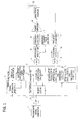
- FIG. 1 is a diagram illustrating a first exemplary configuration of a radio transmission apparatus according to the present embodiment.
- a transmission signal generator 1 transmits a serial digital data string.
- a serial/parallel converter (S/P) 2 performs serial/parallel conversion of the serial digital data string, so as to convert into an I signal and Q signal parallel data string.
- a timing generator 3 generates a timing at which to start updating a distortion compensation coefficient, this timing being after a lapse of a certain period from transmission period start timing, and also generates a timing at which to complete the update of the distortion compensation coefficient, which may occur at transmission period end timing. More specifically, a signal information detector 31 in timing generator 3 detects map information (information indicative of a data position) of the transmission signal from the parallel data string. From the map information and switchover timing between a transmission period and a reception period stored in advance, a preamble detector 32 obtains the transmission period of a top symbol (preamble) in the transmission signal.
- a distortion compensation timing controller 33 outputs a distortion compensation update timing signal to a distortion compensator 4 (making a distortion compensation update timing signal ON) at preamble transmission end timing. Also, distortion compensation timing controller 33 makes the distortion compensation update timing signal OFF at the transmission period end timing to complete the update of the distortion compensation.
- distortion compensation timing controller 33 outputs to distortion compensator 4 a timing signal to start the distortion compensation operation at the transmission period start timing (making a distortion compensation operation timing signal ON) . Also, distortion compensation timing controller 33 makes the distortion compensation operation timing signal OFF at the transmission period end timing.
- the distortion compensation operation is performed in the period from the transmission period start timing to the preamble transmission end timing, the distortion compensation is not updated because the period has large fluctuations in the amplitude and phase of the transmission signal.
- the period in which the distortion compensation is not updated is not limited to the transmission period start timing to the preamble transmission end timing, but can properly be modified depending on the state of fluctuations in the amplitude and phase of the transmission signal.
- the transmission level in the top symbol (preamble) of the transmission signal is approximately 3 dB greater than the transmission level in a data symbol period, by which a conspicuous error may occur easily. Therefore, as one example of the period in which the distortion compensation is not updated, the period from the transmission period start timing to the preamble transmission end timing is exemplified above.
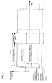
- FIG. 2 is a timing chart of distortion compensation timing controller 33 in the case of TDD-mode communication, wherein each frame is divided in the time domain into a transmission period and a reception period.
- Distortion compensation timing controller 33 outputs the distortion compensation operation timing signal at the transmission period start timing.
- the distortion compensation update timing signal to start the update of the distortion compensation distortion compensation timing controller 33 outputs the above timing signal after the lapse of a certain period from the transmission period start timing (i. e. at the preamble transmission end timing). With this, the distortion compensation coefficient is not obtained in the period immediately after the start of the transmission period in which the amplitude and phase of the transmission signal greatly fluctuate.
- distortion compensation timing controller 33 makes the distortion compensation operation timing signal OFF, and also the distortion compensation coefficient update timing signal OFF, so as to suspend the update of the distortion compensation coefficient in the reception period.
- the distortion compensation coefficient can be prevented from being broken, or in other words maintained until the next frame.
- distortion compensator 4 performs distortion compensation operation on the parallel data string (transmission signal) constituted of the I signal and the Q signal by the above-mentioned distortion compensation operation start timing signal. Also, distortion compensator 4 completes the distortion compensation operation by the distortion compensation operation end timing signal. Further, distortion compensator 4 starts updating the distortion compensation coefficient by the distortion compensation update start timing signal, and suspends the update of the distortion compensation coefficient by the distortion compensation update end timing signal.
- a distortion compensation calculator 41 reads out fromamemory (LUT) 42 the distortion compensation coefficient corresponding to an input transmission signal power level. Distortion compensation calculator 41 then performs predetermined calculation processing on the transmission signal using the read distortion compensation coefficient, and outputs the result thereof.
- Memory (LUT) 42 stores the distortion compensation coefficient corresponding to a two-dimensional coordinate constituted of a transmission signal power level and a power difference between a transmission signal and a feedback signal (for example, the transmission signal at the present time and the feedback signal of the transmission signal at the previous time). Also, based on the power difference between the transmission signal and the feedback signal, distortion compensation calculator 41 calculates a distortion compensation coefficient corresponding to the input transmission signal power, and updates the distortion compensation coefficient stored in memory (LUT) 42. According to the embodiment of the present invention, with regard to the distortion compensation coefficient obtained by distortion compensation calculator 41, interpolation calculation is performed in an interpolation processor 43. Then, the distortion compensation coefficient obtained through the above interpolation calculation is stored into memory (LUT) 42. The interpolation calculation will be described in detail later.
- the distortion-compensated transmission signal output from distortion compensator 4 is input into an orthogonal modulator 6 through a D/A converter 5.
- Orthogonal modulator 6 performs orthogonal modulation by adding the results of multiplying the input transmission signal and a 90° phase-shifted transmission signal respectively by reference carrier waves from a reference carrier wave generator 7.
- a frequency converter 8 converts the transmission signal into a radio frequency signal by mixing the orthogonally modulated signal with a local oscillator signal. After being amplified in a power amplifier 9, the radio frequency signal is transmitted using time division duplex. Also, the transmission signal is looped back inside the radio transmission apparatus through a directional coupler. After being converted into an IF signal by means of a frequency converter 11 and an orthogonal detector 12, the above signal is passed through an A/D converter 13, and fed back to distortion compensator 4 as a feedback signal.
- Distortion compensation update processing to be performed in distortion compensator 4 includes calculation processing based on the transmission signal and the feedback signal, calculation of the distortion compensation coefficient, and periodical update processing. Since the transmission period and the reception period alternate in the TDD scheme, the time available for updating the distortion compensation coefficient is short. As a result, a long time is needed before the coefficient is converged. To cope with the above problem, interpolation calculation processing of the distortion compensation coefficient is performed in interpolation processor 43 of distortion compensator 4, so as to make the convergence time faster and stabilize the coefficient. The interpolation calculation processing of the distortion compensation coefficient will be described in the following.
- FIGS. 3A through 4B are diagrams explaining interpolation processing of the distortion compensation coefficient.
- the distortion compensation coefficient at each coordinate stored in memory (LUT) 42 is updated after interpolation calculation is performed using the distortion compensation coefficients at the adjacent coordinates.
- the memory coordinate is synonymous with an address to identify the location in the memory.
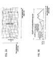
- FIGS. 3A, 3B are diagrams explaining the interpolation processing in a one-dimensional direction
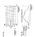
- FIGS. 4A, 4B are diagrams explaining the interpolation processing in a two-dimensional direction.
- FIG. 3A and FIG. 4A are diagrams illustrating mapping configurations of the distortion compensation coefficient stored in memory (LUT) 42.
- a variable in the one-dimensional direction represents a transmission signal power value
- a variable in the two-dimensional direction represents a power difference between a transmission signal and a feedback signal
- a "gradient 0" in the variable of the two-dimensional direction represents a case that the power difference is zero, namely, a case that the power values between the transmission signal and the feedback signal (for example, between the transmission signal at the present time and the feedback signal of the transmission signal at the previous time) are identical.
- Above or below the row of gradient 0 indicates a plus (+) direction of the power difference (i.e. the transmission signal power > the feedback signal power), or a minus (-) direction (i.e. the transmission signal power ⁇ the feedback signal power) respectively.
- FIG. 3B shows distortion compensation coefficients corresponding to variables in the one-dimensional direction when the variable in the two-dimensional direction (power difference) has a predetermined value.
- FIG. 4B shows distortion compensation coefficients corresponding to variables in the two-dimensional direction when the variable in the one-dimensional direction (transmission signal power value) has a predetermined value.
- the initial value of the distortion compensation coefficient is "1+j0" (complex notation).
- interpolation calculation is performed for a coordinate to be interpolated (for example, B in FIG. 3A ), using a distortion compensation coefficient at the coordinate of interest before interpolation and distortion compensation coefficients at the coordinates (A and C in FIG. 3A ) adjacent to the coordinate of interest in the one-dimensional direction.
- the distortion compensation coefficient after the interpolation calculation is obtained.
- an interpolation calculation expression is given by expression (1) shown below.
- each distortion compensation coefficient at each coordinate A, B, C is also represented as A, B, C.
- B ⁇ M - 1 M ⁇ B + A + C 2 ⁇ M
- the distortion compensation coefficient at the coordinate B is obtained through the interpolation calculation of the ratio 2/3 of the distortion compensation coefficient at the coordinate B before the interpolation calculation, the ratio 1/6 of the distortion compensation coefficient at the coordinate A, and the ratio 1/6 of the distortion compensation coefficient at the coordinate C.
- interpolation calculation in the one-dimensional direction using the above expression (1) is performed, using the distortion compensation coefficients at the both adjacent coordinates B and D, so as to obtain the interpolated value of the coordinate C.
- interpolation calculations are successively performed with regard to the coordinates adjacent to the right.
- a distortion compensation coefficient at a coordinate not having the initial distortion compensation coefficient value in the one-dimensional direction is used. For example, in FIG. 3A , to obtain an interpolated value of the coordinate C, if the distortion compensation coefficient at the coordinate D has an initial value and the distortion compensation coefficient at the coordinate E adjacent to the coordinate D in the one-dimensional direction has no initial value, the distortion compensation coefficient at the coordinate E is used in place of the distortion compensation coefficient at the coordinate D.
- the "adjacent coordinate" in expression (1) signifies a coordinate nearest to the coordinate to be interpolated on the either side thereof in the one-dimensional direction, among the coordinates not having the initial distortion compensation coefficient values in the one-dimensional direction.
- the distortion compensation coefficient is used intact even when the initial value is left unchanged.
- the interpolation calculation for the coordinate B even if the coordinate A has the initial value, the interpolated value of the coordinate B is calculated using the above initial value.
- the coordinate on the either end in the one-dimensional direction for example, the coordinate A, H shown in FIG. 3A
- interpolation calculation in the one-dimensional direction is not performed.
- the interpolation calculations in the one-dimensional direction are carried out successively from the left end side (excluding the coordinates on both ends) of a row having a value in the two-dimensional direction of 0 (gradient 0). More specifically, by proceeding to the right direction from the coordinate B, the interpolation calculations are completed up to the last coordinate (G) excluding the coordinate (H) on the right end. Then, with regard to the row lower by one than the row having the gradient 0, the interpolation calculations are carried out from the left end side toward the right end side. Subsequently, after being shifted to the row upper by one than the row having the gradient 0, the interpolation calculations are continued. As such, the interpolation calculations are alternately performed for the rows in the plus direction and the minus direction, with the row having the gradient 0 as a center.
- FIG. 3B shows distortion compensation coefficients in the one-dimensional direction at a predetermined value in the two-dimensional direction and the interpolated values (distortion compensation coefficients after interpolation) thereof.
- smoothing processing is carried out on distortion compensation coefficients which are liable to include a prominent error, as compared to the distortion compensation coefficients at the adjacent coordinates.
- values nearer to the convergence value can be obtained.
- the interpolation processing similar to the interpolation processing in the one-dimensional direction is performed.
- the interpolation calculations are performed using the distortion compensation coefficient at the coordinate concerned before the interpolation and distortion compensation coefficients at the coordinates (A, Q in FIG. 4A ) adjacent to the coordinate concerned in the two-dimensional direction.
- distortion compensation coefficients after interpolation calculations are obtained for the coordinate to be interpolated.
- An expression for interpolation calculation is given, for example, by the following expression (2).
- expression (2) the distortion compensation coefficient at each coordinate A, P, Q is also represented as A, P, Q.
- P ⁇ N - 1 N ⁇ P + A + Q 2 ⁇ N
- the distortion compensation coefficient at the coordinate P is obtained through the interpolation calculation of the ratio 2/3 of the distortion compensation coefficient at the coordinate P before the interpolation calculation, the ratio 1/6 of the distortion compensation coefficient at the coordinate A, and the ratio 1/6 of the distortion compensation coefficient at the coordinate Q.
- interpolation calculation with regard to the coordinate Q in the two-dimensional direction is performed by use of the above expression (2).
- the distortion compensation coefficients at the both adjacent coordinates P and R are used.
- the interpolated value of the coordinate Q is obtained.
- interpolation calculations are successively performed with regard to the coordinates adjacent beneath.
- the above coefficient is not used. Instead, a distortion compensation coefficient at a coordinate not having the initial distortion compensation coefficient value in the two-dimensional direction is used. For example, in FIG. 4A , to obtain an interpolated value of the coordinate Q, if the distortion compensation coefficient at the coordinate R has an initial value, and if the distortion compensation coefficient at the coordinate S adjacent to the coordinate R in the two-dimensional direction has no initial value, the distortion compensation coefficient at the coordinate S is used, in place of the distortion compensation coefficient at the coordinate R.
- the "adjacent coordinate" in expression (2) also signifies a coordinate nearest to the coordinate to be interpolated on the either side thereof in the two-dimensional direction, among the coordinates not having the initial distortion compensation values in the two-dimensional direction.
- the distortion compensation coefficient is used intact even when the initial value is left unchanged.
- the coordinates in the row of gradient 0 are used even when the initial values are left unchanged.
- the coordinates on the both ends in the two-dimensional direction for example, the coordinates T, U, Z in FIG. 4A
- the coordinates in the row of gradient 0 in the one-dimensional direction
- the interpolation calculations in the two-dimensional direction are carried out, for example, from the column on the left end side to the lower end direction from the coordinate P on the lower left end side, with the row of gradient 0 as a center.
- the processing proceeds from a coordinate V on the upper left side to the upper end direction.
- the interpolation calculations are performed to the last coordinate Y excluding the uppermost end coordinate Z.
- the interpolation calculations are carried out alternately on the rows of the lower end side and the rows of the upper end side, with the row having the gradient 0 as a center.
- the aforementioned interpolation calculations in the one-dimensional direction and the interpolation calculations in the two-dimensional direction are carried out in one-time interpolation processing. However, it may also be possible to perform either one thereof. Additionally, when only the interpolation calculations of the two-dimensional direction are performed, first, the interpolation calculations in the one-dimensional direction are performed for the row having the gradient 0. Thereafter, the interpolation calculations in the two-dimensional direction are performed. The reason is that the distortion compensation coefficient in the row having the gradient 0 functions as a criterion.
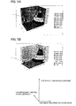
- FIGS. 5A, 5B show diagrams schematically explaining interpolated values of the distortion compensation coefficients obtained through the interpolation calculations.
- FIG. 5A shows distortion compensation coefficients before the interpolation stored in memory (LUT) 42
- FIG. 5B shows distortion compensation coefficients after the interpolation to be stored in memory (LUT) 42.
- the one-dimensional direction represents transmission signal power values
- the two-dimensional direction represents the power difference between the transmission signals and the feedback signals
- the Z direction (vertical axis) represents distortion compensation coefficient values.
- a distortion compensation coefficient for example, a reference symbol 'a' shown in FIG. 5A
- the distortion compensation coefficient values come to have closer correlation with the adjacent distortion compensation coefficients, as shown in FIG. 5B , and a shortened convergence time becomes obtainable.
- Fig. 6 is a diagram illustrating a timing chart of the update processing and the interpolation processing of the distortion compensation coefficient in the TDD scheme.
- distortion compensation calculator 41 calculates the distortion compensation coefficient based on the transmission signal and the feedback signal, and updates the distortion compensation coefficient stored in memory (LUT) 42. Further, in the reception period, since there is neither signal transmission nor the distortion compensation coefficient calculation based on the transmission signal and the feedback signal, the above-mentioned interpolation calculations are carried out by utilizing the above reception period.
- the interpolation processing is not carried out repetitively at any time.
- one-time interpolation processing that is, interpolation calculations for the distortion compensation coefficients in the entire coordinates of memory (LUT) 42 is completed once, thereafter for a certain period
- the interpolation processing is not performed.
- the reason is that if the calculations are performed repetitively at all times, the distortion compensation coefficient becomes too smooth, which undesirably causes a deteriorated distortion characteristic.
- only one-time interpolation processing is carried out in a first reception period after the start of communication (or a reception period in the second or subsequent frame as needed).
- the interpolation processing is executed intermittently.
- the first-time interpolation processing is carried out in the first reception period after the start of communication (or a reception period in the second or later frames as required).
- the processing is performed after the distortion compensation coefficient becomes a converged state. Thereafter, the processing is performed at intervals of a certain period. By performing after the convergence, it is possible to improve the stability of the distortion compensation coefficient further.
- the aforementioned interpolation processing of the distortion compensation coefficient according to the present embodiment is not limited to radio transmission systems using the TDD scheme.
- the above processing is also applicable to a scheme in which simultaneous transmission and reception are performed continuously, such as the FDD scheme enabling simultaneous transmission and reception by use of different transmission and reception frequencies.
- FIG. 7 is a diagram illustrating a timing chart of the update processing and the interpolation processing of the distortion compensation coefficient in the FDD scheme in which continuous transmission is carried out.
- an update processing period and an interpolation processing period are switched alternately in the transmission periods of predetermined symbols (symbols 2, 3 and 6 in FIG. 7 ).
- both the update processing and the interpolation processing can be performed in the transmission period of one symbol. Since there is a case that a difference in the transmission signal levels (power values) is produced symbol-by-symbol, preferably the update processing is performed throughout the entire symbol periods (transmission period for all symbols). However, by assigning an update processing period and an interpolation processing period alternately in one symbol period, it becomes possible to perform necessary update processing, as well as the interpolation processing.
- the update processing and the interpolation processing are switched by dividing one symbol period into six.
- embodiments of the present invention are not limited to the division into six, but may use any arbitrary division number such as 2 and 4.
- the symbol periods for performing the interpolation processing are provided intermittently.
- the interpolation processing is performed in consecutive two (2) symbol periods (symbols 2 and 3) among four (4) symbol periods (symbols 2 through 5), whereas the interpolation processing is not performed in the next 2 symbol periods (symbols 4 and 5).
- the next consecutive 2 symbol periods [symbols 6 and 7 (not shown)] become symbol periods in which the interpolation processing is performed again.
- FIG. 8 is a diagram illustrating a second exemplary configuration of the radio transmission apparatus according to the present embodiment, which is an exemplary configuration to correspond to the timing chart shown in FIG. 7 .
- a timing generator 3 detects the symbol timing, and an update/interpolation timing controller 35 decides whether the detected symbol timing is a symbol period assigned to perform interpolation processing, according to preset period information for the interpolation processing to be performed.
- a switchover signal to divide the symbol period is output according to a preset division number.
- a distortion compensation calculator 41 performs update processing of the distortion compensation coefficients based on the transmission signals (symbols) and the feedback signals, whereas an interpolation processor 43 suspends the interpolation processing of the distortion compensation coefficients.
- interpolation processor 43 performs the interpolation processing of the distortion compensation coefficients, whereas distortion compensation calculator 41 suspends the update processing of the distortion compensation coefficients.
- FIG. 9 is a diagram illustrating a third exemplary configuration of the radio transmission apparatus according to the present embodiment.
- a timing adjuster 14 is further provided for adjusting an output timing of a distortion compensation coefficient update timing signal.
- Timing adjuster 14 controls to shift the output timing (ON timing) of the distortion compensation coefficient update timing signal with a certain time interval width in each transmission period.
- the transmission signal is pattern data (such as synchronization pattern, test data and dummy data), acquisition of similar data having substantially no fluctuations in the amplitude and phase continues. If the update processing of the distortion compensation coefficient is repeated by substantially the same data, an error component accumulates in the distortion compensation coefficient of a particular range. This produces an inappropriate and deteriorated distortion compensation characteristic. Further, because of the above characteristic deterioration, the overall noise floor rises, which is especially noticeable in a portion corresponding to low power in the LUT. Using transmission signals having a variety of amplitudes and phases for distortion compensation update processing, the distortion compensation coefficient is updated randomly in an average manner. Accordingly, it is possible to avoid the above effects.
- pattern data such as synchronization pattern, test data and dummy data
- the distortion compensation coefficient can be smoothed also, and spurious effects and the overall noise floor rise can be suppressed by the smoothed amount. Accordingly, by using both the interpolation processing and the timing adjustment processing described above, it becomes possible to suppress error components more effectively.
- the output timing of the distortion compensation coefficient update timing signal is shifted by a certain interval width in each transmission period.
- data acquisition timing for use in updating the distortion compensation coefficient is shifted.
- FIGS. 10A , 10B show timing charts to explain timing adjustment processing in the third exemplary configuration.
- the distortion compensation coefficient update processing includes element processing of, for example, processing A, processing B, coefficient update processing and processing C in the order of processing sequence.
- a transmission signal data is acquired at the start timing of the coefficient update processing.
- FIG. 10A shows distortion compensation coefficient update processing timing when the timing adjustment processing is not performed by timing adjuster 14.
- FIG. 10B shows distortion compensation coefficient update processing timing when the timing adjustment processing is performed by timing adjuster 14.
- the distortion compensation coefficient update processing is started every time at the same timing after the lapse of a certain time from the start of the transmission period (after the completion of transmission of the top symbol) throughout the entire transmission periods.
- the processing A, the processing B, the "coefficient update”, and the processing C are completed within one transmission period, and processed at the same timing in every transmission period.
- the processing A, B and C are processing related to the distortion compensation coefficient update processing.
- the "coefficient update” is processing to obtain and update the distortion compensation coefficient through calculation based on the data acquired from the transmission signal at the start timing thereof. Accordingly, the timing to acquire the data for calculation performed in the "coefficient update" becomes identical in each transmission period.
- a predetermined suspension time is provided, in addition to the predetermined timing a certain time after the transmission period start timing (after the completion of transmission of the top symbol).
- the distortion compensation coefficient update processing is started at a timing after the lapse of the suspension time.
- the suspension time is made to vary for each transmission period (including a case of no suspension time). Denoting a unit duration of the suspension time to be ⁇ , as shown in the figure, there are set no suspension time for a transmission period 1, a suspension time ⁇ for a transmission period 2, a suspension time 2 ⁇ for a transmission period 3, and a suspension time 3 ⁇ for a transmission period 4.
- the start timing of the distortion compensation coefficient update processing is shifted by a time ⁇ in each transmission period.
- the data acquisition timing in the transmission period is shifted in each transmission period.
- the suspension time is returned to zero. A possible number of times of shifts is obtained in advance from the length of the transmission period and the suspension time.
- the start timing is shifted in each transmission period.
- the process is returned to no suspension time. Then, the shift of the suspension time on the basis of a unit time ⁇ is repeated.
- the length of the time ⁇ can properly be set to the extent that the amplitude variation in the acquired data disperses randomly.
- the entire processing of the distortion compensation coefficient update processing may not be completed before the transmission period end timing.
- the remaining processing is processed in the subsequent transmission period (transmission period 4) .
- the processing is continued in the subsequent reception period.
- FIG. 11 is a processing flowchart of timing adjuster 14.
- Timing adjuster 14 acquires transmission (Tx) symbol information detected by signal information detector 31 (S100), obtains the transmission period length based on the above information, and calculates the possible number (n) of insertion times of the preset suspension unit time ⁇ (i.e. the possible number of times of shift) (S102). Then, timing adjuster 14 initializes the number of insertion counts (CNT1) in one transmission period (hereafter expressed as count CNT1) and the number of really inserted counts (CNT2) in one transmission period (hereafter expressed as real count CNT2) to zeroes (S104, S106).
- count CNT1 the number of insertion counts
- CNT2 real count CNT2
- the count CNT1 is the number of unit times ⁇ to be set in each transmission period, signifying that the greater the count CNT1 is, the longer the suspension time becomes, causing the delayed start of the distortion compensation coefficient update processing.
- timing adjuster 14 measures the lapse of the unit time ⁇ again (S112), and repeats the above measurement of the unit time ⁇ until the real count CNT2 reaches the count CNT1.
- the start timing of the distortion compensation coefficient update processing is shifted by the amount of the measured lapse of the unit time ⁇ .
- an update processing start signal is transmitted to distortion compensation timing controller 33 (S118).
- distortion compensation timing controller 33 On receiving the update processing start signal, distortion compensation timing controller 33 outputs a distortion compensation coefficient update timing signal. Thereby the distortion compensation coefficient update processing is started. Thereafter, on acquiring transmission period end timing information from preamble detector 32 (S120), distortion compensation timing controller 33 increments the count CNT1 by one (S122). By incrementing the count CNT1, the start timing of the distortion compensation coefficient update processing is further delayed by the unit time ⁇ .
- step S106 If the count CNT1 after being incremented is not greater than the possible number (n) of insertion times (S128), in the subsequent transmission period, the process returns to step S106.
- the real count CNT2 is initialized and preamble transmission end timing information is acquired (S108), then the operation from steps S110 through S128 is repeated. If the count CNT1 after being incremented exceeds the possible number (n) of insertion times (S128), in the subsequent transmission period, both the count CNT1 and the real count CNT2 are initialized (S104, S106) . After the preamble transmission end timing information is acquired (S108), the operation from steps S110 through S128 is repeated.
- steps S124 and S126 acquires transmission (Tx) symbol information in each transmission period (S124), and confirms the transmission period length.
- Tx transmission
- S126 transmission period length
- the process is returned to step S102.
- the possible number (n) of insertion times is recalculated, and the processing proceeds to step S104 and thereafter.
- the transmission period length is not varied halfway.
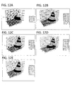
- FIGS. 12A through 12E are diagrams explaining the distortion compensation coefficients on which update processing is performed in the third exemplary configuration.
- FIG. 12A shows distortion compensation coefficients before interpolation stored in memory (LUT) 42, similar to FIG. 5A . Due to the cases of small number of update times and unstable operation of an RF circuit, there is a growth of a distortion compensation coefficient having a prominently large value (hereafter referred to as error component), as compared to the distortion compensation coefficients in the surrounding adjacent coordinates (for example, reference symbols 'a' in FIG. 12A ). As a result, the above error component causes the unnecessary spurious signals and the phenomenon of overall noise floor rise.
- error component a distortion compensation coefficient having a prominently large value
- FIGS. 12B, 12C show distortion compensation coefficients after the interpolation processing.
- an appropriate number of times of interpolation processing are performed, and the error component (reference symbol 'a') is greatly suppressed.
- a greater error component than in FIG. 12B remains partially.
- a relatively large error may possibly remain when the number of times of interpolation processing is excessively small, or when a pattern data such as having a small amplitude variation is used for update processing.
- the distortion compensation coefficient becomes too smoothed, thereby causing a deteriorated distortion characteristic.
- the distortion compensation coefficient corresponding to the peak point is also smoothed, causing the degradation of a high output power transmission function as a transmission amplifier.
- FIG. 12E shows distortion compensation coefficients on which update processing is performed by applying the processing of timing adjuster 14 in the third exemplary configuration.
- the error component is substantially suppressed.
- the start timing of the distortion compensation coefficient update processing is shifted in each transmission period.
- the growth of the error component can be suppressed, and the generated error components can substantially be suppressed through moderate interpolation processing.
- the radio transmission apparatus is applicable to a base station or a mobile station in a TDD or FDD-based radio communication system.
Landscapes
- Engineering & Computer Science (AREA)
- Power Engineering (AREA)
- Physics & Mathematics (AREA)
- Nonlinear Science (AREA)
- Amplifiers (AREA)
- Transmitters (AREA)
Applications Claiming Priority (2)
| Application Number | Priority Date | Filing Date | Title |
|---|---|---|---|
| JP2007271270 | 2007-10-18 | ||
| JP2008119473A JP5146086B2 (ja) | 2007-10-18 | 2008-05-01 | 無線送信装置 |
Publications (2)
| Publication Number | Publication Date |
|---|---|
| EP2051390A2 true EP2051390A2 (fr) | 2009-04-22 |
| EP2051390A3 EP2051390A3 (fr) | 2011-10-19 |
Family
ID=40262912
Family Applications (1)
| Application Number | Title | Priority Date | Filing Date |
|---|---|---|---|
| EP08163606A Withdrawn EP2051390A3 (fr) | 2007-10-18 | 2008-09-03 | Appareil de transmission radio |
Country Status (2)
| Country | Link |
|---|---|
| US (1) | US20090104882A1 (fr) |
| EP (1) | EP2051390A3 (fr) |
Cited By (2)
| Publication number | Priority date | Publication date | Assignee | Title |
|---|---|---|---|---|
| CN102055503B (zh) * | 2009-11-02 | 2014-04-09 | 中兴通讯股份有限公司 | 一种适用于时分双工模式的数字预失真补偿方法及装置 |
| US20220150855A1 (en) * | 2019-03-04 | 2022-05-12 | Telefonaktiebolaget Lm Ericsson (Publ) | Method and Apparatus for Estimating and Compensating Timing Advance |
Families Citing this family (2)
| Publication number | Priority date | Publication date | Assignee | Title |
|---|---|---|---|---|
| JP2016072696A (ja) * | 2014-09-26 | 2016-05-09 | 富士通株式会社 | 歪み補償装置及び歪み補償方法 |
| JP2017069649A (ja) | 2015-09-28 | 2017-04-06 | 富士通株式会社 | 無線装置 |
Citations (6)
| Publication number | Priority date | Publication date | Assignee | Title |
|---|---|---|---|---|
| JPH09153849A (ja) | 1995-11-30 | 1997-06-10 | Fujitsu Ltd | 無線装置 |
| JP2002223171A (ja) | 2001-01-29 | 2002-08-09 | Fujitsu Ltd | 歪補償係数を補正及び補間する非線形歪補償送信装置 |
| JP2006074539A (ja) | 2004-09-03 | 2006-03-16 | Fujitsu General Ltd | 非線形歪補償機能を備えた無線通信機の制御方法、およびそれを用いた無線通信機 |
| JP2006197537A (ja) | 2004-06-29 | 2006-07-27 | Matsushita Electric Ind Co Ltd | 歪補償回路 |
| JP2007271270A (ja) | 2006-03-30 | 2007-10-18 | Calsonic Kansei Corp | 照光モジュール |
| JP2008119473A (ja) | 2006-11-10 | 2008-05-29 | Cheng-Chung Wang | マットレスアセンブリを膨張させるための内蔵の電気式エアポンプユニットを有する可膨張式ベッド |
Family Cites Families (9)
| Publication number | Priority date | Publication date | Assignee | Title |
|---|---|---|---|---|
| JPH08316755A (ja) * | 1995-05-17 | 1996-11-29 | Nippon Motorola Ltd | 間欠的バイアス制御機能を有する電力増幅器及びこれを用いた送信装置 |
| US5870668A (en) * | 1995-08-18 | 1999-02-09 | Fujitsu Limited | Amplifier having distortion compensation and base station for radio communication using the same |
| US5903823A (en) * | 1995-09-19 | 1999-05-11 | Fujitsu Limited | Radio apparatus with distortion compensating function |
| US7212584B2 (en) * | 2002-08-05 | 2007-05-01 | Hitachi Kokusai Electric Inc. | Distortion compensator |
| JP4255361B2 (ja) * | 2003-11-07 | 2009-04-15 | 富士通株式会社 | 歪み補償増幅器 |
| JP4499107B2 (ja) * | 2004-09-13 | 2010-07-07 | 三菱電機株式会社 | 歪補償装置 |
| CN101189792B (zh) * | 2005-03-09 | 2010-07-14 | 富士通株式会社 | 失真补偿装置 |
| JP4682914B2 (ja) * | 2006-05-17 | 2011-05-11 | ソニー株式会社 | 情報処理装置および方法、プログラム、並びに記録媒体 |
| WO2008126217A1 (fr) * | 2007-03-28 | 2008-10-23 | Fujitsu Limited | Dispositif de commande de compensation de distorsion et procédé de commande de compensation de distorsion |
-
2008
- 2008-09-03 EP EP08163606A patent/EP2051390A3/fr not_active Withdrawn
- 2008-10-01 US US12/242,991 patent/US20090104882A1/en not_active Abandoned
Patent Citations (6)
| Publication number | Priority date | Publication date | Assignee | Title |
|---|---|---|---|---|
| JPH09153849A (ja) | 1995-11-30 | 1997-06-10 | Fujitsu Ltd | 無線装置 |
| JP2002223171A (ja) | 2001-01-29 | 2002-08-09 | Fujitsu Ltd | 歪補償係数を補正及び補間する非線形歪補償送信装置 |
| JP2006197537A (ja) | 2004-06-29 | 2006-07-27 | Matsushita Electric Ind Co Ltd | 歪補償回路 |
| JP2006074539A (ja) | 2004-09-03 | 2006-03-16 | Fujitsu General Ltd | 非線形歪補償機能を備えた無線通信機の制御方法、およびそれを用いた無線通信機 |
| JP2007271270A (ja) | 2006-03-30 | 2007-10-18 | Calsonic Kansei Corp | 照光モジュール |
| JP2008119473A (ja) | 2006-11-10 | 2008-05-29 | Cheng-Chung Wang | マットレスアセンブリを膨張させるための内蔵の電気式エアポンプユニットを有する可膨張式ベッド |
Cited By (3)
| Publication number | Priority date | Publication date | Assignee | Title |
|---|---|---|---|---|
| CN102055503B (zh) * | 2009-11-02 | 2014-04-09 | 中兴通讯股份有限公司 | 一种适用于时分双工模式的数字预失真补偿方法及装置 |
| US20220150855A1 (en) * | 2019-03-04 | 2022-05-12 | Telefonaktiebolaget Lm Ericsson (Publ) | Method and Apparatus for Estimating and Compensating Timing Advance |
| US12063614B2 (en) * | 2019-03-04 | 2024-08-13 | Telefonaktiebolaget Lm Ericsson (Publ) | Method and apparatus for estimating and compensating timing advance |
Also Published As
| Publication number | Publication date |
|---|---|
| US20090104882A1 (en) | 2009-04-23 |
| EP2051390A3 (fr) | 2011-10-19 |
Similar Documents
| Publication | Publication Date | Title |
|---|---|---|
| JP5146086B2 (ja) | 無線送信装置 | |
| US6388518B1 (en) | Distortion compensation apparatus | |
| JP4767583B2 (ja) | 歪補償回路 | |
| RU2564680C2 (ru) | Способ определения коэффициентов внесения предыскажений и тракт передачи | |
| KR101120072B1 (ko) | 임의 파형 전치 왜곡 테이블 생성 | |
| EP2365629B1 (fr) | Dispositif de communication et procédé de correction de puissance | |
| KR101098134B1 (ko) | 왜곡 보정 제어 장치 및 왜곡 보정 제어 방법 | |
| US8314656B2 (en) | Power series digital predistorter and distortion compensation control method thereof | |
| EP2262104B1 (fr) | Appareil de communication sans fil | |
| EP2136524B1 (fr) | Appareil de suppression d'amplitude et appareil de transmission de signal | |
| EP2051390A2 (fr) | Appareil de transmission radio | |
| JP3268135B2 (ja) | 無線機 | |
| KR101099228B1 (ko) | 왜곡 보정 제어 장치 및 왜곡 보정 제어 방법 | |
| US20080233878A1 (en) | Radio System and Radio Communication Device | |
| JP5126364B2 (ja) | 送信装置および調整値測定方法 | |
| JP2005348235A (ja) | アレーアンテナ受信装置及び送信装置 | |
| US10056863B2 (en) | Technique for determining a time alignment error | |
| EP1953913B1 (fr) | Dispositif de correction de distorsion | |
| US7995663B2 (en) | Multicarrier transmitting apparatus and multicarrier transmitting method | |
| US8742865B2 (en) | Polar modulation transmission circuit and polar modulation transmission method | |
| JP6790665B2 (ja) | 校正回路、校正方法及びプログラム | |
| JP2007251427A (ja) | 無線装置 | |
| JP2003174370A (ja) | 非線形補償回路と基地局装置および送信電力クリップ方法 | |
| JP2008098781A (ja) | 通信装置 | |
| JP5454014B2 (ja) | 無線装置および送信特性補正方法 |
Legal Events
| Date | Code | Title | Description |
|---|---|---|---|
| PUAI | Public reference made under article 153(3) epc to a published international application that has entered the european phase |
Free format text: ORIGINAL CODE: 0009012 |
|
| AK | Designated contracting states |
Kind code of ref document: A2 Designated state(s): AT BE BG CH CY CZ DE DK EE ES FI FR GB GR HR HU IE IS IT LI LT LU LV MC MT NL NO PL PT RO SE SI SK TR |
|
| AX | Request for extension of the european patent |
Extension state: AL BA MK RS |
|
| PUAL | Search report despatched |
Free format text: ORIGINAL CODE: 0009013 |
|
| AK | Designated contracting states |
Kind code of ref document: A3 Designated state(s): AT BE BG CH CY CZ DE DK EE ES FI FR GB GR HR HU IE IS IT LI LT LU LV MC MT NL NO PL PT RO SE SI SK TR |
|
| AX | Request for extension of the european patent |
Extension state: AL BA MK RS |
|
| RIC1 | Information provided on ipc code assigned before grant |
Ipc: H03F 3/24 20060101ALI20110915BHEP Ipc: H03F 1/32 20060101ALI20110915BHEP Ipc: H04B 1/04 20060101AFI20110915BHEP |
|
| 17P | Request for examination filed |
Effective date: 20120412 |
|
| AKX | Designation fees paid |
Designated state(s): DE FR GB |
|
| STAA | Information on the status of an ep patent application or granted ep patent |
Free format text: STATUS: THE APPLICATION HAS BEEN WITHDRAWN |
|
| 18W | Application withdrawn |
Effective date: 20140107 |