EP2051069A2 - Capteur de gaz paramagnétique et procédé destiné au fonctionnement de celui-ci - Google Patents
Capteur de gaz paramagnétique et procédé destiné au fonctionnement de celui-ci Download PDFInfo
- Publication number
- EP2051069A2 EP2051069A2 EP20080018025 EP08018025A EP2051069A2 EP 2051069 A2 EP2051069 A2 EP 2051069A2 EP 20080018025 EP20080018025 EP 20080018025 EP 08018025 A EP08018025 A EP 08018025A EP 2051069 A2 EP2051069 A2 EP 2051069A2
- Authority
- EP
- European Patent Office
- Prior art keywords
- specimen
- gas sensor
- vibration
- sensor according
- paramagnetic
- Prior art date
- Legal status (The legal status is an assumption and is not a legal conclusion. Google has not performed a legal analysis and makes no representation as to the accuracy of the status listed.)
- Withdrawn
Links
- 0 *C1CCCC1 Chemical compound *C1CCCC1 0.000 description 1
Images

Classifications
-
- G—PHYSICS
- G01—MEASURING; TESTING
- G01N—INVESTIGATING OR ANALYSING MATERIALS BY DETERMINING THEIR CHEMICAL OR PHYSICAL PROPERTIES
- G01N27/00—Investigating or analysing materials by the use of electric, electrochemical, or magnetic means
- G01N27/72—Investigating or analysing materials by the use of electric, electrochemical, or magnetic means by investigating magnetic variables
- G01N27/74—Investigating or analysing materials by the use of electric, electrochemical, or magnetic means by investigating magnetic variables of fluids
- G01N27/76—Investigating or analysing materials by the use of electric, electrochemical, or magnetic means by investigating magnetic variables of fluids by investigating susceptibility
Definitions
- the invention relates to a paramagnetic gas sensor having at least one movably mounted specimen which is in an inhomogeneous magnetic field and within a measuring chamber containing the measuring gas or is surrounded by the measuring gas, and a method of operating the same, according to the preamble of claims 1 and 27.
- a body surrounded by the sample gas is deflected in dependence on the oxygen concentration present in the sample gas.
- the deflection is detected by optical means and determines the oxygen concentration.
- the core of the invention is that the gas sensor is embodied in microstructure technology and that means or at least partially implemented in the microstructure of the sample or the body can be excited to vibrate so that at least one parameter of this vibration, the concentration determination of a sample gas component in the sample gas is vorappelbar.
- the microstructured vibration system is energy-saving due to the small vibration masses and achieves a high quality.
- microstructured gas sensor is built up from a layer structure of structures that can be produced at least partially by the etching process.
- corresponding sensors are arranged in or on the microstructure.
- At least one further oscillating mass is provided which is vibrationally coupled to the first oscillating mass, and forms a spring-mass / specimen system.
- a first is that, to generate an inhomogeneous, static or temporally variable magnetic field, an excitation system implemented at least partially outside the microstructure of the sensor is provided.
- At least one piezoelectric element detects an elastic deformation in the region of the suspension caused by the measurement effect, so that the concentration determination of a sample gas component in the measurement gas can be undertaken at least via a vibration parameter of this detected oscillation.
- a further embodiment provides that the means for generating a forced or resonant oscillation directly in or on the specimen or the sample body suspension are implemented.
- the piezoelectric element is a piezoresistive element, over which the deformation caused by the vibration is detectable.
- the piezoelectric element is a piezocrystal, with which also electrically a deformation for generating a vibration can be generated.
- vibration excitation as well as measurement in the time-division multiplex method can be performed by means of the same piezo elements.
- a further possibility for vibrational excitation results from the fact that a conductor loop which can be induced from the outside is implemented on the same or in the same to generate a vibration of the specimen.
- the magnetic pole shoes are provided with a permanent magnet system and connected.
- a further embodiment for vibration detection or even generation is that the pivotable specimen forms an electrical capacitor with a holding frame fixed in contrast to detect the resulting from the oscillation change in electrical capacitance, from which signal processing technology, the oxygen concentration in the measurement gas can be determined.
- the magnetic pole shoes may also be made for the magnetic pole shoes to be provided and connected to an electromagnetic system.
- a first is that an excitation system is used to generate an inhomogeneous static magnetic field, which is at least partially integrated into the microstructure of the sensor.
- a second is that an excitation system is used to generate an inhomogeneous time-varying magnetic field, which is at least partially integrated into the microstructure of the sensor.
- vibrational alignment two alternatives are given, namely that the specimen is placed and suspended so that it vibrates parallel to the chip surface of the sensor, or that the specimen is placed and suspended so that it vibrates orthogonal to the chip surface of the sensor.
- the plurality of oscillating masses are all specimens.
- at least one further oscillatable mounted sample body is arranged, which is located in the homogeneous magnetic field or in an approximately magnetic field-free region.
- the evaluated vibration parameter is the oscillation frequency, the offset, the amplitude, the decay curve or the damping.
- first and the second sample body are coupled to a common vibration system.
- the evaluated vibration parameter is the phase relationship of the vibrations of the individual bodies to each other.
- the evaluated vibration parameter is the phase relationship of the vibration of the sample body relative to an uncoupled one Reference vibration is.
- the piezoelectric element is arranged in the region of the suspension in which a maximum material expansion takes place.
- the suspension is equipped with a local stress concentrator unit to produce a high material expansion.
- the specimen consists of several symmetrically arranged part bodies of the same shape, the center of gravity of the specimen in the defined by the suspension center of gravity of the system.
- the sample body is formed cross-shaped and is held in its center of gravity by a biaxial suspension.
- the biaxial suspension is formed from two mutually orthogonal suspension axes, which extend from an outer support frame inwards.
- At least one stress concentrator unit is provided per suspension axis, which is located in the intersection region with the cross-shaped sample body.
- the stress concentrator unit is formed from a tapering point of the suspension, in which two piezoresistive elements are arranged radially spaced from each other, in which opposing stresses occur when the suspension is vibrated.
- the radial spacing between the two piezoresistive elements takes place via a gap.
- a bridge circuit of the at least one piezoresistive element is used to optimize the measuring effect present as an electrical signal.
- the area forming the electrical capacitor is separated from the measuring chamber containing the measuring gas.
- the specimen is cross-shaped and is held in its center of gravity by a biaxial suspension.
- the biaxial suspension is formed from two mutually orthogonal suspension axes, which extend from an outer support frame inwards.
- sample body or the spring mass / sample body system is formed tongue-shaped. This takes into account that the sample body does not have to have a centrally-mounted dumbbell-shaped form, but that it can also be hinged and swing on one side like a paddle or a tongue.
- the senor is essentially produced by etching from a solid material.
- the senor consists of substantial proportions of silicon, glass or diamond.
- At least parts of the sensor is produced by deposition methods such as gas phase epitaxy or sputtering.
- the core of the inventive method is that the executed in microstructure gas sensor via at least partially implemented in the microstructure or acting on it means in the region of his specimen or a spring-mass / specimen system it is thus possible to excite vibrations in such a way that the concentration determination of a sample gas component in the measurement gas can be undertaken, at least via one parameter of this oscillation.
- the current concentration of a paramagnetic measurement gas component is determined from at least one vibration parameter by inducing a time-variable current to the sample body via a conductor track structure implemented on or in the same.
- the current concentration of a paramagnetic measurement gas component is determined by the sample body is excited to vibrate for a time dt, and that immediately after completion of the vibration excitation, the vibration relaxation detected and from the vibration parameters of Relaxation the concentration of the measured gas components is determined.
- the vibration excitation carried out so that either arranged on the sample body or the spring mass / sample body system or arranged outside the same piezocrystals are energized so that they are set in vibration.
- vibration excitation occurs externally, z. B. by impact, shock or vibration.
- the excitation will be carried out expediently so that the Vibration excitation of the specimen or spring mass / specimen system always occurs near its resonant frequency.
- the vibration excitation takes place by pulsation of the sample gas stream or another pulsating gas stream.
- vibration excitation is done by sound converter layers based on electrets.
- the evaluated vibration parameter is the oscillation frequency, the offset, the amplitude, the decay curve or the damping or the phase relationship of the vibrations of the specimen or the spring mass / specimen system to one another.
- the evaluated vibration parameter is the phase relationship of the vibration of the sample body relative to an uncoupled reference vibration.
- a capacitive method is that the pivotable specimen forms an electrical capacitor with a holding frame fixed in contrast thereto, in order to detect the change in the electrical capacitance resulting from the pivoting, from which signal processing technology the oxygen concentration in the measuring gas is determined.
- the area forming the electrical capacitor can be separated from the measuring chamber containing the measuring gas.
- Another possibility of vibration detection is similar to the detection of known non-oscillating, ie only deflecting systems, that the vibration parameter (s) are obtained via optical elements (eg., By beam deflection or other influencing of beam parameters). Further methods of reading the vibration parameters are given by inductive elements or electrets.
- the piezoresistive elements can therefore be provided with a bridge circuit.
- the sample body is formed of a plurality of symmetrically arranged part bodies of the same shape, wherein the center of gravity of the sample body is defined by the suspension center of gravity of the system.
- a specimen can be designed cross-shaped and held in its center of gravity by a biaxial suspension.
- the biaxial suspension is preferably formed from two mutually orthogonal suspension axis, which extends from an outer support frame inwardly.
- This preferred embodiment is particularly suitable for producing the paramagnetic oxygen sensor according to the invention with piezoelectric evaluation in the form of a silicon chip.
- the height of the structure in the area of the stress concentrator unit is preferably in the range of 10-500 micrometers.
- the suspension webs have a typical width of 100 microns with the tapers at the location of the stress concentrator unit being in the range of 10-20 microns.
- external dimensions for the silicon sensor can be realized, which are in the range of 10 ⁇ 10 mm 2 - 20 ⁇ 20 mm 2 .
- the paramagnetic oxygen sensor is designed according to the variant of the capacitive evaluation, a similar structure can be implemented.
- a two-axle suspension of two mutually orthogonal suspension axles can also be guided from an outer support frame inwards.
- the specimen itself may preferably also be formed cross-shaped, wherein the holding frame to form an electrical capacitor together with the vibrating specimen receives projections to form corresponding capacitor column.
- An advantageous width of these capacitor gaps is in the range of 10-50 micrometers.
- the width of the suspension of this capacitive variant has a typical width of preferably 10-20 microns.
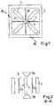
- the arrangement shown is part of a paramagnetic oxygen sensor whose measurement is determined by the detection and evaluation made by the measurement effect caused elastic deformation.
- a here cross-shaped sample body 1 is held in its center of gravity by a biaxial suspension 2.
- the specimen 1 consists of two symmetrically arranged part bodies of the same shape, wherein the center of gravity of the specimen 1 is located in the center of gravity of the system defined by the suspension.
- the two-axle suspension 2 is formed from two mutually orthogonal suspension axles 2a, 2b, which extend inwardly from an outer support frame 3 surrounding the arrangement.
- the consisting of specimen 1, suspension 2 and support frame 3 arrangement is integrally formed, in the form of an etched silicon chip.
- the suspension 2 is equipped to provide a high material expansion with a localderskonzentratoratti 4, within which a - not shown here - piezoresistive element is arranged.
- Section AA illustrates the operation of the paramagnetic oxygen sensor
- the sample body 1 is arranged between two mutually opposite magnetic pole shoes 5a and 5b. In this area there is a measuring chamber 6 containing the measuring gas.
- the measuring effect manifests itself in a cyclic deformation in the region of the suspension 2 caused by oscillation of the sample body 1.
- two piezoresistive elements 7a and 7b are arranged radially spaced from one another in the region of the stress concentrator unit 4 of the suspension 2. Both piezoresistive elements 7a and 7b are connected to electrical conductors 8a and 8b and 8c to form a - not shown - resistance bridge in combination.
- the electrical deformation caused by the measuring effect in the area of the stress concentrator unit 4 causes a corresponding material expansion in the area of the piezoresistive elements 7a and 7b, which convert this material expansion into a corresponding resistance value. From this can be continued - not further shown - signal processing evaluation determine the oxygen concentration in the sample gas.
- the stress concentrator unit 4 of the suspension 2 is here in the intersection region to the cross-shaped specimen 1.
- the stress concentrator 4 is formed from a taper of the suspension 2, wherein the two piezoresistive elements 7a and 7b are arranged radially spaced from each other.
- opposing stresses arise in the piezoresistive elements 7a and 7b.
- the tensile or compressive stresses generated in the piezoresistive elements 7a and 7b lead to an analog increase or decrease of the resistance value.
- the radial spacing between the two piezoresistive elements 7a and 7b is realized via a gap 9, which forms a kind of trench between the two elements.
- This arrangement results in that the distribution of the material stress is more uniform due to unavoidable manufacturing tolerances in the introduction of the piezoresistive elements 7a and 7b with lower resulting tolerances of the electrical output signal of the oxygen sensor is to be expected.
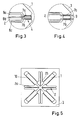
- FIG. 5 illustrated variant of the inventive solution is a capacitive evaluation of the caused by the paramagnetic gas torque of the sample body 1 to.
- the cross-shaped specimen 1 is - exactly as in the variant described above - held by a biaxial suspension 2, which consists of two mutually orthogonal suspension axis 2a and 2b, which extend from an outer support frame 3 inwardly.
- this variant of the support frame 3 is also provided with inwardly extending projections, which together with sections of the sample body 1 form an electrical capacitor.
- FIG. 6 shows a configuration, according to another alternative, namely according to claim 4 et seq.
- a sample body 40 is excited to vibrate in an inhomogeneous magnetic field (eg by a time-varying current in a conductor loop applied to the sample body).
- a sample body 80 is excited to oscillate in a similar manner but in a homogeneous magnetic field.
- Both specimens 40, 80 are connected via resilient suspension systems 30 and 60 with their structural environment.
- the position of both specimens is recorded. This can be done by a capacitive or inductive position detection system. It is also conceivable to indirectly detect the position of the specimens by measuring the stress ratios in the suspension system (e.g., by implanted piezoresistors such as in the form described above).
- probe bodies coupled to one another which also influence one another mechanically, or rotationally oscillating specimens (this would have advantages with regard to a further reduced influence of external accelerations given a corresponding design of the body (balancing)).
- the vibration excitation (in particular of the specimen B) does not have to be done by a conductor loop in a magnetic field. This could also be coupled to specimen A via spring elements to perform a vibratory motion without separate drive.
- the vibration excitation can also be done by other mechanisms. It is also conceivable to put the overall structure into action by external vibration excitation and to measure the characteristic of the oscillation within the sensor.
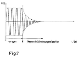
- FIG. 7 shows the measurement of the vibration parameters in the relaxation phase.
- an excitation of the oscillatory system thus the sample body, and at time A, the excitation is stopped, and the oscillation relaxes d..h it runs from then on until it comes to rest.
- the relaxation time and the ascertainable damping parameters are then used to calculate the actual oxygen concentration.
- the oscillation excitation can take place up to the time A via the application of electrical voltage to the piezocrystals, while at time A, this is switched off, and instead the output voltage generated at the piezocrystal by the oscillation-induced deformation is measured, ie the oscillation in the Relaxation phase is measured.
Landscapes
- Chemical & Material Sciences (AREA)
- Chemical Kinetics & Catalysis (AREA)
- Electrochemistry (AREA)
- Physics & Mathematics (AREA)
- Health & Medical Sciences (AREA)
- Life Sciences & Earth Sciences (AREA)
- Analytical Chemistry (AREA)
- Biochemistry (AREA)
- General Health & Medical Sciences (AREA)
- General Physics & Mathematics (AREA)
- Immunology (AREA)
- Pathology (AREA)
- Investigating Or Analyzing Materials By The Use Of Magnetic Means (AREA)
Applications Claiming Priority (1)
| Application Number | Priority Date | Filing Date | Title |
|---|---|---|---|
| DE102007049867A DE102007049867A1 (de) | 2007-10-18 | 2007-10-18 | Paramagnetischer Gassensor sowie Verfahren zum Betrieb desselben |
Publications (1)
| Publication Number | Publication Date |
|---|---|
| EP2051069A2 true EP2051069A2 (fr) | 2009-04-22 |
Family
ID=40251711
Family Applications (1)
| Application Number | Title | Priority Date | Filing Date |
|---|---|---|---|
| EP20080018025 Withdrawn EP2051069A2 (fr) | 2007-10-18 | 2008-10-15 | Capteur de gaz paramagnétique et procédé destiné au fonctionnement de celui-ci |
Country Status (2)
| Country | Link |
|---|---|
| EP (1) | EP2051069A2 (fr) |
| DE (1) | DE102007049867A1 (fr) |
Cited By (1)
| Publication number | Priority date | Publication date | Assignee | Title |
|---|---|---|---|---|
| US9789127B2 (en) | 2002-02-12 | 2017-10-17 | Hunza Di Pistolesi Elvira & C. S.A.S. | N-acyl-phosphatidyl-ethanolamines and/or mixtures of N-acyl-ethanolamines with phosphatidic acids or lysophosphatidic acids |
Families Citing this family (1)
| Publication number | Priority date | Publication date | Assignee | Title |
|---|---|---|---|---|
| DE102015122506A1 (de) * | 2015-12-22 | 2017-06-22 | Analytik Jena Ag | Verfahren und Vorrichtung zur Bestimmung eines Anteils eines Elements in einer Probe |
Citations (1)
| Publication number | Priority date | Publication date | Assignee | Title |
|---|---|---|---|---|
| DE19803990A1 (de) | 1998-02-02 | 1999-06-02 | Siemens Ag | Verfahren und Vorrichtung zur Konzentrationsmessung paramagnetischer Gasanteile in einem Gasgemisch |
Family Cites Families (3)
| Publication number | Priority date | Publication date | Assignee | Title |
|---|---|---|---|---|
| FR2668264B1 (fr) * | 1990-10-18 | 1994-02-04 | Rennes I Universite | Capteur de mesure de la concentration d'oxygene dans un gaz. |
| AU2003215788A1 (en) * | 2002-03-22 | 2003-10-08 | Instrumentarium Corporation | Paramagnetic oxygen sensing apparatus and method |
| DE102006021308B4 (de) * | 2006-04-20 | 2008-09-04 | Abb Ag | Paramagnetische Sauerstoffmesseinrichtung, sowie Verfahren zur Herstellung und zum Betrieb einer solchen Sauerstoffmesseinrichtung |
-
2007
- 2007-10-18 DE DE102007049867A patent/DE102007049867A1/de not_active Ceased
-
2008
- 2008-10-15 EP EP20080018025 patent/EP2051069A2/fr not_active Withdrawn
Patent Citations (1)
| Publication number | Priority date | Publication date | Assignee | Title |
|---|---|---|---|---|
| DE19803990A1 (de) | 1998-02-02 | 1999-06-02 | Siemens Ag | Verfahren und Vorrichtung zur Konzentrationsmessung paramagnetischer Gasanteile in einem Gasgemisch |
Cited By (1)
| Publication number | Priority date | Publication date | Assignee | Title |
|---|---|---|---|---|
| US9789127B2 (en) | 2002-02-12 | 2017-10-17 | Hunza Di Pistolesi Elvira & C. S.A.S. | N-acyl-phosphatidyl-ethanolamines and/or mixtures of N-acyl-ethanolamines with phosphatidic acids or lysophosphatidic acids |
Also Published As
| Publication number | Publication date |
|---|---|
| DE102007049867A1 (de) | 2009-04-30 |
Similar Documents
| Publication | Publication Date | Title |
|---|---|---|
| DE112005002196B4 (de) | Drehratensensor | |
| DE19530007C2 (de) | Drehratensensor | |
| EP1364184B1 (fr) | Capteur de vitesse de rotation | |
| DE69735726T2 (de) | Abschirm-bänder für stimmgabel-gyroskope | |
| DE3417858C2 (fr) | ||
| DE19827056A1 (de) | Mikromechanischer Magnetfeldsensor | |
| DE102010061755A1 (de) | Drehratensensor und Verfahren zum Betrieb eines Drehratensensors | |
| EP1472506B1 (fr) | Capteur de vitesse de rotation micromecanique | |
| WO2017071864A1 (fr) | Capteur mems pour la mesure d'au moins une grandeur de mesure d'un fluide | |
| DE102012200125B4 (de) | Sensorstruktur und Drehratensensor | |
| DE102004030380B4 (de) | Mikromechanischer Drucksensor und Verfahren zum Selbsttest eines solchen | |
| DE102009036175B4 (de) | MEMS-Silizium-Resonatorbauelement und Verfahren zur Bestimmung seiner Resonanzfrequenz | |
| DE69726142T2 (de) | Schachtelförmiger miniatur-vibrationskreisel | |
| DE19937747C2 (de) | Mechanischer Resonator für Rotationssensor | |
| EP2051069A2 (fr) | Capteur de gaz paramagnétique et procédé destiné au fonctionnement de celui-ci | |
| DE10040537B4 (de) | Mikromechanischer Drehratensensor und Verfahren zu seiner Herstellung | |
| EP2423654B1 (fr) | Capteur micromécanique doté d'une caractéristique de passage de bande | |
| EP1608988B1 (fr) | Capteur d'acceleration et procede de detection d'une acceleration | |
| DE102020130558A1 (de) | Antrieb für einen Vibrationssensor, Vibrationssensor und Verwendung von Formgedächtnismaterialien als Antriebselement in Vibrationssensoren sowie Verfahren zum Antrieb eines Vibrationssensors | |
| DE19723333A1 (de) | Drucksensor | |
| DE102018112506B3 (de) | Vibrationssensor mit optischer Schwingungsmessung | |
| EP3060933B1 (fr) | Magnétomètre à gradients, et procédé de détermination d'un composant individuel d'un capteur à gradients d'un champ magnétique | |
| AT513634B1 (de) | MEMS-Sensor zur Detektion von Umgebungsparametern | |
| DE102005032684A1 (de) | Detektor zum Nachweis von Teilchen in einer gasförmigen Atmosphäre und Verfahren zu dessen Auslegung | |
| DE102007018834A1 (de) | Drehratensensor |
Legal Events
| Date | Code | Title | Description |
|---|---|---|---|
| PUAI | Public reference made under article 153(3) epc to a published international application that has entered the european phase |
Free format text: ORIGINAL CODE: 0009012 |
|
| AK | Designated contracting states |
Kind code of ref document: A2 Designated state(s): AT BE BG CH CY CZ DE DK EE ES FI FR GB GR HR HU IE IS IT LI LT LU LV MC MT NL NO PL PT RO SE SI SK TR |
|
| AX | Request for extension of the european patent |
Extension state: AL BA MK RS |
|
| STAA | Information on the status of an ep patent application or granted ep patent |
Free format text: STATUS: THE APPLICATION IS DEEMED TO BE WITHDRAWN |
|
| 18D | Application deemed to be withdrawn |
Effective date: 20110701 |