EP3060933B1 - Magnétomètre à gradients, et procédé de détermination d'un composant individuel d'un capteur à gradients d'un champ magnétique - Google Patents
Magnétomètre à gradients, et procédé de détermination d'un composant individuel d'un capteur à gradients d'un champ magnétique Download PDFInfo
- Publication number
- EP3060933B1 EP3060933B1 EP14803034.9A EP14803034A EP3060933B1 EP 3060933 B1 EP3060933 B1 EP 3060933B1 EP 14803034 A EP14803034 A EP 14803034A EP 3060933 B1 EP3060933 B1 EP 3060933B1
- Authority
- EP
- European Patent Office
- Prior art keywords
- sensor
- gradient
- beams
- amplitude
- longitudinal direction
- Prior art date
- Legal status (The legal status is an assumption and is not a legal conclusion. Google has not performed a legal analysis and makes no representation as to the accuracy of the status listed.)
- Not-in-force
Links
Images


Classifications
-
- G—PHYSICS
- G01—MEASURING; TESTING
- G01R—MEASURING ELECTRIC VARIABLES; MEASURING MAGNETIC VARIABLES
- G01R33/00—Arrangements or instruments for measuring magnetic variables
- G01R33/02—Measuring direction or magnitude of magnetic fields or magnetic flux
- G01R33/028—Electrodynamic magnetometers
- G01R33/0286—Electrodynamic magnetometers comprising microelectromechanical systems [MEMS]
-
- G—PHYSICS
- G01—MEASURING; TESTING
- G01R—MEASURING ELECTRIC VARIABLES; MEASURING MAGNETIC VARIABLES
- G01R33/00—Arrangements or instruments for measuring magnetic variables
- G01R33/02—Measuring direction or magnitude of magnetic fields or magnetic flux
- G01R33/022—Measuring gradient
Definitions
- the present invention relates to a gradient magnetometer comprising an arrangement of a plurality of sensors, each sensor comprising a rectilinear beam which is fixed in a longitudinal direction and an end region in its longitudinal direction and can swing freely therebetween, each sensor further comprising at least one arranged on the beam and conducting means connected therewith to allow a current flow in the form of moving charge carriers between the starting region and the end region, wherein the at least one conducting means is acted upon by an alternating voltage to excite a vibrating mode of the beam by utilizing the Lorentz force, when the Beam is located in a magnetic field, wherein at least two sensors are mechanically coupled to each other in order to force the same oscillation frequency upon excitation of a shrinkage of the beams of these at least two sensors.
- the measurement of a gradient of a magnetic field plays a role in various fields of technology and science. For example, it is used to position a gear in an ABS sensor for a vehicle or to accurately measure the earth's magnetic field.
- the strength of the magnetic field can be described by the magnetic flux density B. Its gradient results from the change in B per unit distance in the direction of the largest change in B. Since B is a vectorial quantity, which is generally itself a function of all three spatial coordinates, the gradient is basically a tensor from all the partial derivatives of the three spatial B-field components according to the spatial coordinates.
- two magnetic field sensors for example Hall sensors, are used to measure the gradient, usually measuring the size of B at two different locations located at a well-defined distance from each other. The difference between the measured values for B is then formed and divided by the distance. The distance should be chosen so as to ensure that the B-field is linear within the Distance varies. This is achieved in that the distance between the sensors is small compared to the distance between the positions of the sensors and the source of the magnetic field.
- This two-sensor method has the fundamental, unavoidable drawback that there are not completely identical sensors, i. the sensors will always have at least slightly different characteristics, which is why the difference in the measured B fields is extremely susceptible to errors.
- the sensors have only a limited sensitivity, which makes it necessary to place the two sensors relatively far apart to determine differences in B, which of course reduces the spatial resolution. This can not be avoided even if only one sensor is used, which is positioned one behind the other at the two different locations for the B measurement.
- a sensor that can be used to detect a magnetic flux density gradient.
- the sensor has for this purpose a plurality of parallel bars, along each bar current can be directed.
- the bars are interconnected by a vibrating element whose deflection or displacement can be determined.
- opposite alternating current is conducted along opposing beams.
- there is a displacement of the vibrating element since the occurring Lorentz forces do not compensate.
- the net resulting Lorentz force causes the amplitude with which the oscillating element oscillates to be changed.
- a magnetometer having a first and a second beam, which are mechanically coupled to each other via an insulating bridge, so that in top view of the device is given an H-shape.
- the first bar is excited to vibrate, and due to the mechanical coupling also the second bar oscillates at the same frequency.
- an oscillating voltage is induced in the second beam by the oscillations, which voltage can be tapped at tapping points, wherein the second beam is electrically connected to the tapping points. Since the amplitude of the induced voltage depends on the size of the magnetic field, Thus, the size of the magnetic field can be determined.
- a gradient magnetometer comprising an elastically deformable membrane, on which a permanent magnet is arranged.
- the resulting torque causes a deformation of the membrane which can be measured to account for the field gradient.
- a magnetic field sensor with a conductor loop which has deformable longitudinal sides.
- an oscillating surface change of the surface of the conductor loop is generated, which generates an induced voltage at connection pads in the presence of a magnetic field.
- an improved spatial resolution is to be achieved.
- a rectilinear beam which is fixed at its beginning and end in its longitudinal direction and freely therebetween can oscillate in a magnetic field by utilizing the Lorentz force to oscillate with a vibrational mode of the beam, the amplitude of the excited vibration mode being directly proportional to a single component of the gradient magnetic field or magnetic flux density B.
- the core of the present invention is that by mechanical coupling of at least two such beams - in contrast to the use of two independent and spaced apart swinging beams - systematic errors can be prevented and can be realized in a simple manner, a precise gradient magnetometer.
- At least one - electrical - conducting means is provided, which is arranged on the respective beam and connected to this, in order to allow a current flow in the form of moving charge carriers between the beginning and end region. If the charge carriers move in a magnetic field, the Lorentz force acts on them. Due to the coupling between the at least one guide means and the beam also acts on these the Lorentz force. If now the at least one conducting means is subjected to an alternating voltage and the bar is in a magnetic field, an oscillation of the bar is excited on account of the resulting oscillating Lorentz force. Basically, the beam behaves like a vibrating string, which is fixed at both ends. Accordingly, there are vibration modes of the beam, which can be excited by utilizing a resonance. This basically works regardless of whether the B-field is zero on average or not, more precisely, regardless of whether the gradient is superimposed by a DC or non-zero DC field.
- the sensor is a rectilinear Beam, which is fixed in a longitudinal direction in an initial region and an end portion and can swing freely between them, the sensor further comprising at least one arranged on the beam and connected thereto Leitsch to a current flow in the form of moving charge carriers between the initial region and End range to allow, wherein the at least one conducting means is acted upon by an AC voltage to excite using the Lorentz force a vibration mode of the beam when the beam is in a magnetic field.
- a second sensor or a second bar is provided, which runs parallel to the first bar. To ensure that both beams vibrate at the same frequency, the two beams are mechanically coupled together.
- This arrangement has increased sensitivity to a component of the magnetic field gradient with respect to a single sensor in a partial direction in the spatial direction corresponding to the longitudinal direction of the beam (hereinafter simply referred to as a component of the magnetic field gradient "along" the longitudinal direction).
- a further advantage of this arrangement is that a spacing of the two sensors or beams in a direction normal to the longitudinal direction, preferably in the first direction, simultaneously results in a sensitivity of the arrangement to a component of a magnetic field gradient along this direction, ie Detection of a component of the magnetic field gradient with a partial derivative in this direction allows.
- each sensor comprises a rectilinear beam which is fixed in a longitudinal direction and an end portion and freely oscillates therebetween, each sensor further comprising at least one arranged on the beam and with this connected conducting means, to allow a current flow in the form of moving charge carriers between the starting region and the end region, wherein the at least one conducting means is acted upon by an alternating voltage to excite using the Lorentz force a vibration mode of the beam when the beam in a magnetic field is at least two sensors are mechanically coupled to each other to force the same oscillation frequency upon excitation of a shrinkage of the beams of these at least two sensors, according to the invention provided that at least one read-out means vorges for each sensor is to determine an amplitude of the oscillation of the beam of the respective sensor.
- the relevant component of the gradient tensensor is a B-field component partially derived according to that spatial coordinate corresponding to the longitudinal direction of the beam. Which spatial B-field component is involved depends on the spatial direction along which the amplitude is measured. Specifically, the direction of the respective amplitude results from the cross product between the direction of the (alternating) current and the relevant B-field component.
- Simple detection is achieved by allowing for oscillations of amplitude in a preferred direction become.
- the bar of each sensor in the longitudinal direction between the initial region and the end region has a length such that the beam normal in a first direction has a width in the longitudinal direction and a height in a second direction normal to the longitudinal direction and the first direction, wherein the height is smaller than the width and the width is smaller than the length.
- the amplitude in the second direction does not necessarily have to be measured;
- the amplitude can also be measured in another, arbitrary direction, in particular in the first direction.
- amplitudes in several directions per bar can be determined simultaneously, e.g. both the amplitude in the first direction and the amplitude in the second direction. In this case, it is of course advisable to provide a separate read-out means for each sensor or bar for each amplitude to be measured.
- the width is at least ten times greater, preferably at least thirty times greater than the height and the length at least ten times greater, preferably at least thirty times greater than the width.
- the ratios of the axial area moment of inertia with respect to the different directions are therefore in a ratio of at least 1: 100, corresponding to the width-to-length or height-to-width ratio.
- the beam of each sensor is made of preferably monocrystalline silicon. This allows, for example, the production based on a silicon wafer in a so-called, known silicone-on-insulator (SOI) method.
- SOI silicone-on-insulator
- a manufacturing technology advantageous embodiment results in that a conductor track, preferably made of gold, is provided as the guide means.
- the conductor runs correspondingly along the longitudinal direction of the beam. Therefore, in a preferred embodiment of the gradient magnetometer according to the invention, it is provided that the at least one conducting means comprises a conductor track which is fixed on a surface of the bar of each sensor.
- the at least one conductive agent is integrated in the beam of each sensor.
- the at least one conductive agent may be, for example be designed as a micromechanical structure made of metal, in particular aluminum.
- the at least one conducting means is mechanically damaged or even destroyed by the vibrations of the beam
- the beam and the at least one conducting means of each sensor are made in one piece. That In this case, the beam itself is at least partially electrically conductive.
- the beams are interconnected by means of at least one coupling element, wherein the arrangement has an essentially H-shape.
- the arrangement need not have perfect symmetry, i. the at least one coupling element must e.g. not perfectly centered with respect to the length of the beams.
- the cross-section of the beams is normal or constant to the longitudinal direction over the entire length of the beams. Accordingly, in general, no symmetrical arrangement can be assumed.
- the bars of the two sensors are arranged offset from one another only in the first or second direction. Such an arrangement can easily be produced by means of the already mentioned SOI technology. Accordingly, it is provided in a preferred embodiment of the gradient magnetometer according to the invention that the bars of the two sensors are parallel to each other and are substantially spaced apart from each other only in the first direction.
- the SOI technology makes it possible to manufacture the beams of the two sensors and the at least one connecting element connecting the beams in a simple manner in one piece. So there are no additional steps for fixing the at least one coupling element to the beam. In addition, a very well-defined arrangement is obtained. Accordingly, it is provided in a preferred embodiment of the gradient magnetometer according to the invention that the two beams and the at least one coupling element are made in one piece.
- each beam is fixed in its initial region and in its end region to a respective anchor element designed as a cantilever is.
- the thus executed anchor elements are themselves subject to thermal expansion and are arranged to the H-shaped arrangement that the thermal expansion of the H-shaped arrangement is compensated, whereby a buckling is prevented.
- each beam and the associated anchor elements are made in one piece.
- SOI technology is also used in this case for the production.
- a particularly easy-to-implement read-out means is a capacitive readout element.
- This can be formed by the bar itself and an electrode arranged under the bar.
- the electrode is at least partially parallel to the beam when it is not vibrating and is in an initial position.
- the electrode and the beam in principle form a capacitor with a certain capacity, which depends on the distance between the electrode and the beam. If the beam oscillates, the capacitance changes as a function of its deflection or of the amplitude of the oscillation. Accordingly, it can be concluded from the measurement of the capacitance change on the amplitude and thus on the size or on the amount of the component of the magnetic field gradient tensor. Accordingly, in a preferred embodiment of the gradient magnetometer according to the invention, it is provided that a capacitive read-out element is provided as the respective at least one read-out means.
- a piezoelectric or piezoresistive or optical read-out element is provided as the respective at least one read-out means.
- a vibration mode of the beam is excited and the amplitude of the excited vibration mode is measured.
- Optimum resonant excitation is achieved by having the AC voltage or resulting AC current at a frequency f i , where f i is a frequency of a vibration mode of the beam.
- the size of the Component of the gradient tensensor of B is obtained by multiplying the measured amplitude by a proportionality factor. It should be noted that in principle both symmetric and antisymmetric modes of vibration can be excited, in principle, in both cases, the determination of the size of the tensor component is possible. If the gradient is superimposed by a non-zero DC field, the excitation of an antisymmetric mode of vibration to determine the size of the component of the gradient sensor of B may be advantageous to facilitate a distinction between the DC field component and the gradient tensor component.
- the Lorentz force F L results basically as a product of the gradient of B with the magnetic moment, which in turn results from the current flow in the conducting means and the area enclosed by the current flow.
- a a which represents the maximum deflection in the general direction a, ie normal to the direction x and normal to the normal direction a '
- an oscillation of the beam of a second sensor which is mechanically coupled to the sensor, is excited by utilizing the Lorentz force by the at least one conducting means of the second sensor is supplied with an alternating voltage with the same frequency f i , and that the amplitudes of the excited vibration of the two bars are determined.
- K A z * ⁇ e . J y . m . l .
- K the component of the magnetic flux density in the first direction partially derived in the longitudinal direction
- a z the amplitude measured along the second direction
- J y the axial area moment of inertia of the beam with respect to the first direction.
- ⁇ is again the proportionality factor, where E is clearly again the modulus of elasticity of the beam, m is the magnetic moment, which results from the current flow in the conducting means and the area enclosed by the current flow, and l the length of the beam.
- the use of the arrangement according to the invention also makes it possible to detect a component of the magnetic field gradient with a partial derivative in that direction normal to the longitudinal direction, in which the two beams are spaced from one another.
- the B-field component in the first direction may be partially derived in the first direction (" ⁇ B y / ⁇ y"). If this component of the gradient tensensor is not equal to zero, then, when a respective symmetrical oscillation mode of the beams is excited, the beams will oscillate out of phase. Therefore, in a preferred embodiment of the invention Method is provided, that also determines whether the vibration of the two bars is in phase or out of phase.
- the occurrence of antiphase oscillations of the beams is of great advantage, as this allows a difference signal of the read-out means by means of which the amplitudes are measured to be generated very easily and without additional computational effort.
- the realization of a differential capacitor in a capacitive readout of the amplitudes would be possible.
- the gradient magnetometer according to the invention or the method according to the invention also makes it possible to determine B-field components. If, for example, in the first direction only a dc field of non-zero magnetic flux density is present, but no gradient tensensor component is nonzero, the corresponding B-field component ("B y ”) can be determined in the same way by exciting a symmetric vibration mode of a single beam as described above for the determination of the gradient tensensor component. In this case, it is only to be considered that in this case the Lorentz force F L which causes the uniform load acting on the beam is the product of the current i in the conducting means, the length l of the beam and the said B-field component results.
- B a ' is the B-field component in the normal direction a' and ⁇ is a proportionality factor which depends on E, J a ' , i and l.
- an in-phase oscillation occurs when a symmetrical oscillation mode of the two bars is excited, if in the first direction only a dc field of the magnetic flux density is not equal to zero.
- anti-phase alternating currents could be applied in this case, anti-phase alternating currents.
- the invention therefore provides for the use of a gradient magnetometer according to the invention for determining a single component of a gradient sensor of a magnetic field and / or for determining a single component of the magnetic flux density.
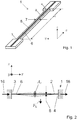
- Fig. 1 shows in an axonometric view a sensor 1 of a gradient magnetometer according to the invention for determining individual components of a gradient tensensor of a magnetic field or a magnetic flux density B.
- the sensor 1 comprises a beam 2 which extends along a longitudinal direction x with a length l. Relative to the longitudinal direction, the beam 2 is fixed in an initial region 3 and an end region 4 and can oscillate freely between the initial region 3 and the end region 4 - similar to a clamped string.
- the beam has a substantially rectangular cross-section normal to the longitudinal direction x, with a width 7 and a height 8, cf. Fig. 2 ,
- the width 7 is measured along a first direction y, the height 8 along a second direction z, with the directions x, y and z mutually normal.
- the cross-sectional shape does not necessarily have to be square, but for example, could be elliptical.
- the length l is significantly greater than the width 7 and the width 7 significantly greater than the height 8. Accordingly, there are very different axial area moments of inertia about or with respect to the different directions x, y and z, so that the beam preferably in the second Direction z can be deflected or oscillates with amplitudes in the direction z.
- the presentation of the Fig. 1 is not to scale. Typical dimensions are 2500 ⁇ m for the length l, 500 ⁇ m for the width 7 and 5 ⁇ m for the height 8.
- a conductor track 5 is arranged as an electrical conducting means to a current flow in the form of moving charge carriers between the Start area 3 and the end 4 to allow. Due to the dominating dimension of the beam 2 in the longitudinal direction x, the conductor track 5 on the surface 6 can be approximated as a one-dimensional element with extension in the direction x.
- the conductor track 5 is subjected to an alternating voltage when the sensor 1 is in the magnetic field. Due to the resulting alternating current 16 in the conductor track 5, the Lorentz force F L acts on the charge carriers moving in the conductor track 5 and subsequently on the bars 2. Since this is an alternating current, the Lorentz force F L changes its sign in time and thus causes an alternating deflection or oscillation of the beam 2.
- a suitable frequency f i of the alternating current 16 is selected, vibration modes of the beam 2 can be excited resonantly.
- Fig. 2 illustrates the situation for a flux density B perpendicular to the plane of the drawing and a symmetric mode of oscillation of the beam 2. That is, B is parallel to the direction y, or has a component in the first direction y, B y which is non-zero, ie B y Die 0.
- the amplitude A z of the vibration mode results as the maximum deflection of the beam 2 parallel to the direction z, wherein the deflection in Fig. 2 is indicated by the dashed or dotted line.
- the maximum deflection in direction z or the amplitude A z is directly proportional to B y .
- an amplitude A a is measured in a general direction a.
- the component K to be determined is then the magnetic flux density B in a normal direction a 'which is normal to the direction of the measured amplitude A a and is normal to the longitudinal direction x, partially derived according to the longitudinal direction x, ie " ⁇ B a, / ⁇ x".
- the amplitude A z of a vibration mode is proportional to the corresponding partial derivative of B y according to a spatial coordinate corresponding to the longitudinal direction x.
- J y is the axial area moment of inertia of the beam 2 with respect to the first direction y.
- the spatial resolution of the measurement of K in the direction x is thus determined by the length l of the beam 2.
- the excitation of an antisymmetric mode of vibration to determine the size of the component of the gradient sensor of B may be advantageous in order to distinguish between Simultaneous field component and gradient tensor component simplify.
- the amplitude A z of the illustrated antisymmetric vibration mode of the beam 2 is measured to close immediately to the size of K or ⁇ B y / ⁇ x.
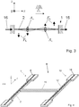
- Fig. 4 shows an assembly 9 consisting of the sensor 1 and a second sensor 10 with a second beam 12 and a second conductor 18, wherein the second sensor 10 basically corresponds to the first sensor 1 in construction. Also, the second conductor 18 is acted upon by an alternating voltage, wherein a second alternating current 17 sets (see. Fig. 5 ), so that in a magnetic field of the second beam 12 can be excited to vibrate.
- the two beams 2, 12 are connected to each other via a coupling element 11, resulting in an H-shape of the assembly 9.
- the two sensors 1, 10 and the beams 2, 12 are arranged parallel to each other and spaced apart only in the first direction y.
- the coupling element 11 ensures that both bars 2, 12 oscillate at the same frequency.
- the first sensor 1 of Fig. 1 to Fig. 3 and the arrangement 9 of the Fig. 4 with the first sensor 1, the second sensor 10 and the coupling element 11 may be made of preferably monocrystalline silicon, for example.
- the conductor tracks 5, 18 may be made of gold, for example.
- the sensor 1 or the arrangement 9 can be produced by means of the known silicone-on-insulator (SOI) technology.
- Fig. 5 first shows the case of a DC magnetic field with a B-component in the first direction y not equal to 0, ie B y ⁇ 0.
- Analog to Fig. 2 swing both beams 2, 12, with a symmetric vibration mode with the amplitude A z in the second direction z.
- the two beams 2, 12 oscillate in phase.
- the two AC voltages or the first AC 16 and the second AC 17 not only have the same frequency f i , but are also in-phase.
- B y 0 vanishing on average
- the two alternating voltages or the two alternating currents 16, 17 are in phase and again swing the two beams 2, 12 each with a symmetric vibration mode with the amplitude A z in the second direction z. Due to the gradient tensensor component ⁇ B y / ⁇ y ⁇ 0, however, an opposite-phase oscillation of the beams 2, 12 results in this case.
- the out-of-phase deflection of the two beams 2, 12 offers the metrological advantage that a difference signal can be obtained from the measurements of the amplitudes A z without much effort.
- the measurement of the amplitude (n) can be carried out with a wide variety of read-out means, which may include, for example, capacitive, piezoelectric, piezoresistive or optical read-out elements.
- Fig. 7 shows a plan view of an inventive arrangement 9 with in-phase alternating currents 16, 17.
- the beams 2, 12 are fixed in their initial areas 3, 19 and end portions 4, 20 to one anchor member 14.
- each beam 2, 12 is connected both in its initial region 3, 19 and in its end region 4, 20 via a respective connecting portion 15, each with an anchor element 14.
- the armature elements 14 are subject to a thermally induced expansion.
- the anchor elements 14 are designed as cantilevers and arranged accordingly, causes the thermal expansion of the anchor members 14 that there is no thermally induced buckling of the beams 2, 12. In this sense, compensates the thermal expansion of the anchor members 14, the thermal expansion of the beams 2, 12 and the assembly 9.
- Manufacturing technology advantageously beams 2, 12, coupling member 11, connecting portions 15 and anchor members 14 may be made in one piece, preferably the SOI technology used for the production.
- Fig. 8 shows a section along the section line AA in Fig. 7 ,
- capacitive readout elements 13 for determining the deflection of the beams 2, 12 in the second direction z or for determining the amplitude A z of the beams 2, 12 can be seen.
- the readout elements 13 are indicated by the dotted lines.
- the readout elements 13 are formed in each case by one of the beams 2, 12 together with the associated conducting means or together with the associated conductor track 5, 18 and an electrode 21 arranged below the respective beam 2, 12, which can be designed, for example, as a conductor track.
- the distance between the beam 2, 12 and the associated electrode 21 changes, whereby the capacitive coupling between the respective electrode 21 and the respective conductor track 5, 18 or the resulting capacitance changes.
- the capacitance change is therefore a direct measure of the amplitude A z .
Landscapes
- Physics & Mathematics (AREA)
- Condensed Matter Physics & Semiconductors (AREA)
- General Physics & Mathematics (AREA)
- Measuring Magnetic Variables (AREA)
Claims (15)
- Magnétomètre à gradient comprenant une disposition de plusieurs capteurs (1) dans laquelle chaque capteur (1) comprend une barre rectiligne (2) qui est fixée, vue dans la direction longitudinale (x), dans une zone de début (3) et une zone de fin (4) et qui peut vibrer librement entre celles-ci, chaque capteur (1) comprenant en outre au moins un moyen de conduction (5) disposé sur la barre (2) et relié à celle-ci afin de permettre un écoulement de courant sous la forme d'un déplacement de porteurs de charge entre la zone de début (3) et la zone de fin (4), l'au moins un moyen de conduction (5) pouvant recevoir une tension alternative afin de susciter un mode de vibration de la barre (2) en exploitant la force de Lorentz (FL) quand la barre (2) se trouve dans un champ magnétique, au moins deux capteurs (1) étant couplés mécaniquement l'un à l'autre afin d'imposer la même fréquence de vibration quand des vibrations des barres (2) de ces au moins deux capteurs (1) sont suscitées, caractérisé en ce qu'il est prévu pour chaque capteur (1) au moins un moyen de lecture pour déterminer une amplitude (Aa, Az) des vibrations de la barre (2) du capteur (1) en question.
- Magnétomètre à gradient selon la revendication 1, caractérisé en ce que la barre (2) chaque capteur (1) présente dans la direction longitudinale (x) entre la zone de début (3) et la zone de fin (4) une longueur (1) telle que la barre (2) présente dans une première direction (y) perpendiculaire à la direction longitudinale (x) une largeur (7) et dans une deuxième direction (z) perpendiculaire à la direction longitudinale (x) et à la première direction (y) une hauteur (8), la hauteur (8) étant plus petite que la largeur (7) et la largeur (7) plus petite que la longueur (1).
- Magnétomètre à gradient selon la revendication 2, caractérisé en ce que la largeur (7) est au moins dix fois plus grande, de préférence au moins trente fois plus grande que la hauteur (8) et la longueur (1) est au moins dix fois plus grande, de préférence au moins trente fois plus grande que la largeur (7).
- Magnétomètre à gradient selon l'une des revendications 1 à 3, caractérisé en ce que la barre (2) de chaque capteur (1) est faite de silicium, de préférence monocristallin.
- Magnétomètre à gradient selon l'une des revendications 1 à 4, caractérisé en ce que l'au moins un moyen de conduction comprend une piste conductrice (5) qui est fixée sur une surface (6) de la barre (2) chaque capteur (1).
- Magnétomètre à gradient selon l'une des revendications 1 à 4, caractérisé en ce que l'au moins un moyen de conduction (5) est intégré dans la barre (2) de chaque capteur (1).
- Magnétomètre à gradient selon la revendication 6, caractérisé en ce que la barre (2) et l'au moins un moyen de conduction (5) de chaque capteur (1) sont réalisés d'une pièce.
- Magnétomètre à gradient selon l'une des revendications 1 à 7, caractérisé en ce que sont prévus exactement deux capteurs (1, 10) dont les barres (2, 12) sont reliées l'une à l'autre au moyen d'au moins un élément de couplage (11), la disposition présentant sensiblement la forme d'un H.
- Magnétomètre à gradient selon la revendication 8, caractérisé en ce que les barres (2, 12) des deux capteurs (1, 10) sont parallèles l'une à l'autre et ne sont distantes l'une de l'autre, pour l'essentiel, que dans la première direction (y).
- Magnétomètre à gradient selon l'une des revendications 8 à 9, caractérisé en ce que les deux barres (2, 12) et l'au moins un élément de couplage (11) sont réalisées d'une pièce.
- Magnétomètre à gradient selon l'une des revendications 8 à 10, caractérisé en ce que chaque barre (2, 12) est fixé dans sa zone de début (3) et dans sa zone de fin (4) sur un élément d'ancrage (14) réalisé comme un bras en porte-à-faux.
- Procédé pour la détermination une individuelle composante (K) d'un tenseur de gradient d'un champ magnétique à l'aide d'un capteur (1) muni d'une barre rectiligne (2) qui est fixée, vue dans la direction longitudinale (x), dans une zone de début (3) et une zone de fin (4) et qui peut vibrer librement entre celles-ci, le capteur (1) comprenant en outre au moins un moyen de conduction (5) disposé sur la barre (2) et relié à celle-ci, afin de permettre un écoulement de courant sous la forme d'un déplacement de porteurs de charge entre la zone de début (3) et la zone de fin (4), lequel procédé comprend au moins les étapes suivantes :- excitation d'un mode vibratoire de préférence antisymétrique de la barre (2) du capteur (1) en exploitant la force de Lorentz (FL) par le fait que l'au moins un moyen de conduction (5) reçoit une tension alternative de fréquence fi, où fi est une fréquence d'un mode vibratoire de la barre (2) ;caractérisé en ce que le procédé comprend les étapes suivantes :- détermination d'une amplitude (Aa) des vibrations suscitées ;- calcul de la grandeur de la composante (K) selon la formule suivante :et dans lequel, en même temps que les vibrations de la barre (2) du capteur (1) sont suscitées, des vibrations de la barre (12) d'une deuxième capteur (10) couplé mécaniquement au capteur (1) sont suscitées en exploitant la force de Lorentz (FL) par le fait que l'au moins un moyen de conduction (5) du deuxième capteur (10) reçoit une tension alternative de la même fréquence fi, et en ce que les amplitudes (Aa) des vibrations suscitées des deux barres (2, 12) sont déterminées.

- Procédé selon la revendication 12, caractérisé en ce que l'amplitude est mesurée dans la deuxième direction (z) et en ce que la composante (K) du capteur de gradient est déterminée selon la formule suivante :

- Procédé selon l'une des revendications 12 à 13, caractérisé en ce qu'il est déterminé en outre si les vibrations des deux barres (2, 12) sont en phase ou de phase opposée.
- Procédé selon l'une des revendications 12 à 14, caractérisé en ce que les deux tensions alternatives sont de phase opposée.
Applications Claiming Priority (2)
| Application Number | Priority Date | Filing Date | Title |
|---|---|---|---|
| ATA821/2013A AT515000B1 (de) | 2013-10-23 | 2013-10-23 | Gradientenmagnetometer und Verfahren zur Bestimmung einer einzelnen Komponente eines Gradiententensors eines Magnetfelds |
| PCT/AT2014/050254 WO2015058229A1 (fr) | 2013-10-23 | 2014-10-23 | Magnétomètre à gradients, et procédé de détermination d'un composant individuel d'un capteur à gradients d'un champ magnétique |
Publications (2)
| Publication Number | Publication Date |
|---|---|
| EP3060933A1 EP3060933A1 (fr) | 2016-08-31 |
| EP3060933B1 true EP3060933B1 (fr) | 2018-04-25 |
Family
ID=52992030
Family Applications (1)
| Application Number | Title | Priority Date | Filing Date |
|---|---|---|---|
| EP14803034.9A Not-in-force EP3060933B1 (fr) | 2013-10-23 | 2014-10-23 | Magnétomètre à gradients, et procédé de détermination d'un composant individuel d'un capteur à gradients d'un champ magnétique |
Country Status (3)
| Country | Link |
|---|---|
| EP (1) | EP3060933B1 (fr) |
| AT (1) | AT515000B1 (fr) |
| WO (1) | WO2015058229A1 (fr) |
Families Citing this family (1)
| Publication number | Priority date | Publication date | Assignee | Title |
|---|---|---|---|---|
| FR3073284B1 (fr) * | 2017-11-08 | 2020-11-13 | Commissariat Energie Atomique | Capteur de gradient de champ magnetique a sensibilite aux vibrations reduite |
Family Cites Families (9)
| Publication number | Priority date | Publication date | Assignee | Title |
|---|---|---|---|---|
| DE19809742A1 (de) * | 1998-03-06 | 1999-09-16 | Bosch Gmbh Robert | Magnetfeldsensor |
| US6275034B1 (en) * | 1998-03-11 | 2001-08-14 | Analog Devices Inc. | Micromachined semiconductor magnetic sensor |
| GB9910932D0 (en) * | 1999-05-11 | 1999-07-07 | Gravitec Instr Ltd | Measurement of magnetic fields |
| US6812696B2 (en) * | 2000-03-21 | 2004-11-02 | The Johns Hopkins University | Apparatus and methods using mechanical resonators to enhance sensitivity in lorentz force magnetometers |
| US7394245B2 (en) * | 2003-09-23 | 2008-07-01 | Qinetiq Limited | Resonant magnetometer device |
| GB0329959D0 (en) * | 2003-12-24 | 2004-01-28 | Qinetiq Ltd | Magnetic field sensor |
| US7253615B2 (en) * | 2004-05-05 | 2007-08-07 | General Electric Company | Microelectromechanical system sensor and method for using |
| US7429858B2 (en) * | 2004-07-13 | 2008-09-30 | Lucent Technologies Inc. | Oscillating-beam magnetometer |
| FR2942883B1 (fr) * | 2009-03-06 | 2011-05-13 | Commissariat Energie Atomique | Capteur de gradient d'une composante d'un champ magnetique a aimant permanent |
-
2013
- 2013-10-23 AT ATA821/2013A patent/AT515000B1/de not_active IP Right Cessation
-
2014
- 2014-10-23 EP EP14803034.9A patent/EP3060933B1/fr not_active Not-in-force
- 2014-10-23 WO PCT/AT2014/050254 patent/WO2015058229A1/fr active Application Filing
Non-Patent Citations (1)
| Title |
|---|
| None * |
Also Published As
| Publication number | Publication date |
|---|---|
| WO2015058229A1 (fr) | 2015-04-30 |
| AT515000B1 (de) | 2016-09-15 |
| EP3060933A1 (fr) | 2016-08-31 |
| AT515000A1 (de) | 2015-05-15 |
Similar Documents
| Publication | Publication Date | Title |
|---|---|---|
| DE3417858C2 (fr) | ||
| DE60032373T2 (de) | Mikromechanisch hergestellter stimmgabelkreisel und zugehöriges dreiachsiges inertialmesssystem zur messung von drehungen ausserhalb der ebene | |
| DE19530007C2 (de) | Drehratensensor | |
| DE102009046807B4 (de) | Verfahren zur Empfindlichkeitsbestimmung eines Beschleunigungs- oder Magnetfeldsensors | |
| EP2100151B1 (fr) | Capteur z micromécanique | |
| DE112012003562B4 (de) | Verbesserte Detektionsstruktur für einen z-Achsen-Resonanzbeschleunigungsmesser | |
| DE60032100T2 (de) | Mikrokreisel mit zwei resonanten Platten | |
| DE19801981C2 (de) | Winkelgeschwindigkeitssensor vom Vibrationstyp | |
| EP3368867B1 (fr) | Capteur mems pour la mesure d'au moins une grandeur mesurable d'un fluide | |
| DE102015110711A1 (de) | MEMS Sensor zu Messung mindestens einer Messgröße eines strömenden Fluids | |
| EP0765464B1 (fr) | Capteur de vitesse angulaire | |
| DE602004009204T2 (de) | Wandler zur Winkelgeschwindigkeitsmessung | |
| DE10230528B4 (de) | Verbesserungen in bzw. bezüglich eines Systems der Beseitigung der Abweichung für ein Schwinggyroskop | |
| WO2009077263A1 (fr) | Capteur de vitesse de rotation et son procédé de fonctionnement | |
| DE4327052A1 (de) | Vorrichtung zur Massemessung von Flüssigkeiten und Gasen | |
| EP1060401B1 (fr) | Detecteur de champ magnetique | |
| EP3060933B1 (fr) | Magnétomètre à gradients, et procédé de détermination d'un composant individuel d'un capteur à gradients d'un champ magnétique | |
| DE112018000491T5 (de) | Sensorelement, Winkelgeschwindigkeitssensor und Multiaxialwinkelgeschwindigkeitssensor | |
| DE4424635B4 (de) | Mikromechanischer Beschleunigungssensor | |
| DE102005010393B4 (de) | Halbleitersensor zur Erfassung einer dynamischen Grösse | |
| EP2153170B1 (fr) | Capteur de vitesse de rotation | |
| DE102017219933A1 (de) | Drehratensensor mit einem eine Haupterstreckungsebene aufweisenden Substrat, Herstellungsverfahren für einen Drehratensensor | |
| AT523342B1 (de) | Sensor | |
| DE60114037T2 (de) | Gerät zur messung des drucks eines fluids | |
| EP3601973B1 (fr) | Capteur de force |
Legal Events
| Date | Code | Title | Description |
|---|---|---|---|
| PUAI | Public reference made under article 153(3) epc to a published international application that has entered the european phase |
Free format text: ORIGINAL CODE: 0009012 |
|
| 17P | Request for examination filed |
Effective date: 20160517 |
|
| AK | Designated contracting states |
Kind code of ref document: A1 Designated state(s): AL AT BE BG CH CY CZ DE DK EE ES FI FR GB GR HR HU IE IS IT LI LT LU LV MC MK MT NL NO PL PT RO RS SE SI SK SM TR |
|
| AX | Request for extension of the european patent |
Extension state: BA ME |
|
| DAX | Request for extension of the european patent (deleted) | ||
| GRAP | Despatch of communication of intention to grant a patent |
Free format text: ORIGINAL CODE: EPIDOSNIGR1 |
|
| INTG | Intention to grant announced |
Effective date: 20171218 |
|
| GRAA | (expected) grant |
Free format text: ORIGINAL CODE: 0009210 |
|
| GRAS | Grant fee paid |
Free format text: ORIGINAL CODE: EPIDOSNIGR3 |
|
| AK | Designated contracting states |
Kind code of ref document: B1 Designated state(s): AL AT BE BG CH CY CZ DE DK EE ES FI FR GB GR HR HU IE IS IT LI LT LU LV MC MK MT NL NO PL PT RO RS SE SI SK SM TR |
|
| REG | Reference to a national code |
Ref country code: GB Ref legal event code: FG4D Free format text: NOT ENGLISH |
|
| REG | Reference to a national code |
Ref country code: CH Ref legal event code: EP |
|
| REG | Reference to a national code |
Ref country code: CH Ref legal event code: NV Representative=s name: RENTSCH PARTNER AG, CH Ref country code: AT Ref legal event code: REF Ref document number: 993489 Country of ref document: AT Kind code of ref document: T Effective date: 20180515 |
|
| REG | Reference to a national code |
Ref country code: IE Ref legal event code: FG4D Free format text: LANGUAGE OF EP DOCUMENT: GERMAN |
|
| REG | Reference to a national code |
Ref country code: DE Ref legal event code: R096 Ref document number: 502014008093 Country of ref document: DE |
|
| REG | Reference to a national code |
Ref country code: NL Ref legal event code: MP Effective date: 20180425 |
|
| REG | Reference to a national code |
Ref country code: LT Ref legal event code: MG4D |
|
| PG25 | Lapsed in a contracting state [announced via postgrant information from national office to epo] |
Ref country code: NL Free format text: LAPSE BECAUSE OF FAILURE TO SUBMIT A TRANSLATION OF THE DESCRIPTION OR TO PAY THE FEE WITHIN THE PRESCRIBED TIME-LIMIT Effective date: 20180425 |
|
| REG | Reference to a national code |
Ref country code: FR Ref legal event code: PLFP Year of fee payment: 5 |
|
| PG25 | Lapsed in a contracting state [announced via postgrant information from national office to epo] |
Ref country code: ES Free format text: LAPSE BECAUSE OF FAILURE TO SUBMIT A TRANSLATION OF THE DESCRIPTION OR TO PAY THE FEE WITHIN THE PRESCRIBED TIME-LIMIT Effective date: 20180425 Ref country code: PL Free format text: LAPSE BECAUSE OF FAILURE TO SUBMIT A TRANSLATION OF THE DESCRIPTION OR TO PAY THE FEE WITHIN THE PRESCRIBED TIME-LIMIT Effective date: 20180425 Ref country code: LT Free format text: LAPSE BECAUSE OF FAILURE TO SUBMIT A TRANSLATION OF THE DESCRIPTION OR TO PAY THE FEE WITHIN THE PRESCRIBED TIME-LIMIT Effective date: 20180425 Ref country code: SE Free format text: LAPSE BECAUSE OF FAILURE TO SUBMIT A TRANSLATION OF THE DESCRIPTION OR TO PAY THE FEE WITHIN THE PRESCRIBED TIME-LIMIT Effective date: 20180425 Ref country code: NO Free format text: LAPSE BECAUSE OF FAILURE TO SUBMIT A TRANSLATION OF THE DESCRIPTION OR TO PAY THE FEE WITHIN THE PRESCRIBED TIME-LIMIT Effective date: 20180725 Ref country code: FI Free format text: LAPSE BECAUSE OF FAILURE TO SUBMIT A TRANSLATION OF THE DESCRIPTION OR TO PAY THE FEE WITHIN THE PRESCRIBED TIME-LIMIT Effective date: 20180425 Ref country code: BG Free format text: LAPSE BECAUSE OF FAILURE TO SUBMIT A TRANSLATION OF THE DESCRIPTION OR TO PAY THE FEE WITHIN THE PRESCRIBED TIME-LIMIT Effective date: 20180725 |
|
| PG25 | Lapsed in a contracting state [announced via postgrant information from national office to epo] |
Ref country code: HR Free format text: LAPSE BECAUSE OF FAILURE TO SUBMIT A TRANSLATION OF THE DESCRIPTION OR TO PAY THE FEE WITHIN THE PRESCRIBED TIME-LIMIT Effective date: 20180425 Ref country code: RS Free format text: LAPSE BECAUSE OF FAILURE TO SUBMIT A TRANSLATION OF THE DESCRIPTION OR TO PAY THE FEE WITHIN THE PRESCRIBED TIME-LIMIT Effective date: 20180425 Ref country code: LV Free format text: LAPSE BECAUSE OF FAILURE TO SUBMIT A TRANSLATION OF THE DESCRIPTION OR TO PAY THE FEE WITHIN THE PRESCRIBED TIME-LIMIT Effective date: 20180425 Ref country code: GR Free format text: LAPSE BECAUSE OF FAILURE TO SUBMIT A TRANSLATION OF THE DESCRIPTION OR TO PAY THE FEE WITHIN THE PRESCRIBED TIME-LIMIT Effective date: 20180726 |
|
| PG25 | Lapsed in a contracting state [announced via postgrant information from national office to epo] |
Ref country code: PT Free format text: LAPSE BECAUSE OF FAILURE TO SUBMIT A TRANSLATION OF THE DESCRIPTION OR TO PAY THE FEE WITHIN THE PRESCRIBED TIME-LIMIT Effective date: 20180827 |
|
| REG | Reference to a national code |
Ref country code: DE Ref legal event code: R097 Ref document number: 502014008093 Country of ref document: DE |
|
| PG25 | Lapsed in a contracting state [announced via postgrant information from national office to epo] |
Ref country code: SK Free format text: LAPSE BECAUSE OF FAILURE TO SUBMIT A TRANSLATION OF THE DESCRIPTION OR TO PAY THE FEE WITHIN THE PRESCRIBED TIME-LIMIT Effective date: 20180425 Ref country code: EE Free format text: LAPSE BECAUSE OF FAILURE TO SUBMIT A TRANSLATION OF THE DESCRIPTION OR TO PAY THE FEE WITHIN THE PRESCRIBED TIME-LIMIT Effective date: 20180425 Ref country code: DK Free format text: LAPSE BECAUSE OF FAILURE TO SUBMIT A TRANSLATION OF THE DESCRIPTION OR TO PAY THE FEE WITHIN THE PRESCRIBED TIME-LIMIT Effective date: 20180425 Ref country code: CZ Free format text: LAPSE BECAUSE OF FAILURE TO SUBMIT A TRANSLATION OF THE DESCRIPTION OR TO PAY THE FEE WITHIN THE PRESCRIBED TIME-LIMIT Effective date: 20180425 Ref country code: RO Free format text: LAPSE BECAUSE OF FAILURE TO SUBMIT A TRANSLATION OF THE DESCRIPTION OR TO PAY THE FEE WITHIN THE PRESCRIBED TIME-LIMIT Effective date: 20180425 |
|
| PG25 | Lapsed in a contracting state [announced via postgrant information from national office to epo] |
Ref country code: SM Free format text: LAPSE BECAUSE OF FAILURE TO SUBMIT A TRANSLATION OF THE DESCRIPTION OR TO PAY THE FEE WITHIN THE PRESCRIBED TIME-LIMIT Effective date: 20180425 Ref country code: IT Free format text: LAPSE BECAUSE OF FAILURE TO SUBMIT A TRANSLATION OF THE DESCRIPTION OR TO PAY THE FEE WITHIN THE PRESCRIBED TIME-LIMIT Effective date: 20180425 |
|
| PLBE | No opposition filed within time limit |
Free format text: ORIGINAL CODE: 0009261 |
|
| STAA | Information on the status of an ep patent application or granted ep patent |
Free format text: STATUS: NO OPPOSITION FILED WITHIN TIME LIMIT |
|
| 26N | No opposition filed |
Effective date: 20190128 |
|
| PG25 | Lapsed in a contracting state [announced via postgrant information from national office to epo] |
Ref country code: SI Free format text: LAPSE BECAUSE OF FAILURE TO SUBMIT A TRANSLATION OF THE DESCRIPTION OR TO PAY THE FEE WITHIN THE PRESCRIBED TIME-LIMIT Effective date: 20180425 |
|
| REG | Reference to a national code |
Ref country code: BE Ref legal event code: MM Effective date: 20181031 |
|
| PG25 | Lapsed in a contracting state [announced via postgrant information from national office to epo] |
Ref country code: LU Free format text: LAPSE BECAUSE OF NON-PAYMENT OF DUE FEES Effective date: 20181023 Ref country code: MC Free format text: LAPSE BECAUSE OF FAILURE TO SUBMIT A TRANSLATION OF THE DESCRIPTION OR TO PAY THE FEE WITHIN THE PRESCRIBED TIME-LIMIT Effective date: 20180425 |
|
| REG | Reference to a national code |
Ref country code: IE Ref legal event code: MM4A |
|
| PG25 | Lapsed in a contracting state [announced via postgrant information from national office to epo] |
Ref country code: BE Free format text: LAPSE BECAUSE OF NON-PAYMENT OF DUE FEES Effective date: 20181031 |
|
| PG25 | Lapsed in a contracting state [announced via postgrant information from national office to epo] |
Ref country code: IE Free format text: LAPSE BECAUSE OF NON-PAYMENT OF DUE FEES Effective date: 20181023 |
|
| PG25 | Lapsed in a contracting state [announced via postgrant information from national office to epo] |
Ref country code: AL Free format text: LAPSE BECAUSE OF FAILURE TO SUBMIT A TRANSLATION OF THE DESCRIPTION OR TO PAY THE FEE WITHIN THE PRESCRIBED TIME-LIMIT Effective date: 20180425 |
|
| PG25 | Lapsed in a contracting state [announced via postgrant information from national office to epo] |
Ref country code: MT Free format text: LAPSE BECAUSE OF FAILURE TO SUBMIT A TRANSLATION OF THE DESCRIPTION OR TO PAY THE FEE WITHIN THE PRESCRIBED TIME-LIMIT Effective date: 20180425 |
|
| PG25 | Lapsed in a contracting state [announced via postgrant information from national office to epo] |
Ref country code: TR Free format text: LAPSE BECAUSE OF FAILURE TO SUBMIT A TRANSLATION OF THE DESCRIPTION OR TO PAY THE FEE WITHIN THE PRESCRIBED TIME-LIMIT Effective date: 20180425 |
|
| PG25 | Lapsed in a contracting state [announced via postgrant information from national office to epo] |
Ref country code: HU Free format text: LAPSE BECAUSE OF FAILURE TO SUBMIT A TRANSLATION OF THE DESCRIPTION OR TO PAY THE FEE WITHIN THE PRESCRIBED TIME-LIMIT; INVALID AB INITIO Effective date: 20141023 Ref country code: CY Free format text: LAPSE BECAUSE OF FAILURE TO SUBMIT A TRANSLATION OF THE DESCRIPTION OR TO PAY THE FEE WITHIN THE PRESCRIBED TIME-LIMIT Effective date: 20180425 Ref country code: MK Free format text: LAPSE BECAUSE OF NON-PAYMENT OF DUE FEES Effective date: 20180425 |
|
| PG25 | Lapsed in a contracting state [announced via postgrant information from national office to epo] |
Ref country code: IS Free format text: LAPSE BECAUSE OF FAILURE TO SUBMIT A TRANSLATION OF THE DESCRIPTION OR TO PAY THE FEE WITHIN THE PRESCRIBED TIME-LIMIT Effective date: 20180825 |
|
| REG | Reference to a national code |
Ref country code: AT Ref legal event code: MM01 Ref document number: 993489 Country of ref document: AT Kind code of ref document: T Effective date: 20191023 |
|
| PG25 | Lapsed in a contracting state [announced via postgrant information from national office to epo] |
Ref country code: AT Free format text: LAPSE BECAUSE OF NON-PAYMENT OF DUE FEES Effective date: 20191023 |
|
| PGFP | Annual fee paid to national office [announced via postgrant information from national office to epo] |
Ref country code: DE Payment date: 20211020 Year of fee payment: 8 Ref country code: GB Payment date: 20211022 Year of fee payment: 8 |
|
| PGFP | Annual fee paid to national office [announced via postgrant information from national office to epo] |
Ref country code: FR Payment date: 20211021 Year of fee payment: 8 Ref country code: CH Payment date: 20211022 Year of fee payment: 8 |
|
| REG | Reference to a national code |
Ref country code: DE Ref legal event code: R119 Ref document number: 502014008093 Country of ref document: DE |
|
| REG | Reference to a national code |
Ref country code: CH Ref legal event code: PL |
|
| GBPC | Gb: european patent ceased through non-payment of renewal fee |
Effective date: 20221023 |
|
| PG25 | Lapsed in a contracting state [announced via postgrant information from national office to epo] |
Ref country code: LI Free format text: LAPSE BECAUSE OF NON-PAYMENT OF DUE FEES Effective date: 20221031 Ref country code: FR Free format text: LAPSE BECAUSE OF NON-PAYMENT OF DUE FEES Effective date: 20221031 Ref country code: DE Free format text: LAPSE BECAUSE OF NON-PAYMENT OF DUE FEES Effective date: 20230503 Ref country code: CH Free format text: LAPSE BECAUSE OF NON-PAYMENT OF DUE FEES Effective date: 20221031 |
|
| PG25 | Lapsed in a contracting state [announced via postgrant information from national office to epo] |
Ref country code: GB Free format text: LAPSE BECAUSE OF NON-PAYMENT OF DUE FEES Effective date: 20221023 |