EP2050940A1 - Verfahren zur herstellung eines mehrstufigen abgasturbolader - Google Patents
Verfahren zur herstellung eines mehrstufigen abgasturbolader Download PDFInfo
- Publication number
- EP2050940A1 EP2050940A1 EP07792323A EP07792323A EP2050940A1 EP 2050940 A1 EP2050940 A1 EP 2050940A1 EP 07792323 A EP07792323 A EP 07792323A EP 07792323 A EP07792323 A EP 07792323A EP 2050940 A1 EP2050940 A1 EP 2050940A1
- Authority
- EP
- European Patent Office
- Prior art keywords
- pressure
- low
- stage turbocharger
- turbocharger
- pressure stage
- Prior art date
- Legal status (The legal status is an assumption and is not a legal conclusion. Google has not performed a legal analysis and makes no representation as to the accuracy of the status listed.)
- Granted
Links
- 238000004519 manufacturing process Methods 0.000 title claims abstract description 10
- 239000000470 constituent Substances 0.000 claims abstract description 8
- 238000005266 casting Methods 0.000 claims description 7
- 238000003466 welding Methods 0.000 claims description 7
- 238000002485 combustion reaction Methods 0.000 claims description 5
- 238000000034 method Methods 0.000 claims description 4
- 230000003247 decreasing effect Effects 0.000 description 7
- 229910052751 metal Inorganic materials 0.000 description 4
- 239000002184 metal Substances 0.000 description 4
- 238000010276 construction Methods 0.000 description 3
- 238000007789 sealing Methods 0.000 description 2
- 229920001875 Ebonite Polymers 0.000 description 1
- 229910000831 Steel Inorganic materials 0.000 description 1
- 229910052782 aluminium Inorganic materials 0.000 description 1
- XAGFODPZIPBFFR-UHFFFAOYSA-N aluminium Chemical compound [Al] XAGFODPZIPBFFR-UHFFFAOYSA-N 0.000 description 1
- 238000009434 installation Methods 0.000 description 1
- 239000000463 material Substances 0.000 description 1
- 238000005058 metal casting Methods 0.000 description 1
- 239000007769 metal material Substances 0.000 description 1
- 230000002093 peripheral effect Effects 0.000 description 1
- 229920005989 resin Polymers 0.000 description 1
- 239000011347 resin Substances 0.000 description 1
- 239000010959 steel Substances 0.000 description 1
Images


Classifications
-
- F—MECHANICAL ENGINEERING; LIGHTING; HEATING; WEAPONS; BLASTING
- F02—COMBUSTION ENGINES; HOT-GAS OR COMBUSTION-PRODUCT ENGINE PLANTS
- F02B—INTERNAL-COMBUSTION PISTON ENGINES; COMBUSTION ENGINES IN GENERAL
- F02B39/00—Component parts, details, or accessories relating to, driven charging or scavenging pumps, not provided for in groups F02B33/00 - F02B37/00
-
- F—MECHANICAL ENGINEERING; LIGHTING; HEATING; WEAPONS; BLASTING
- F01—MACHINES OR ENGINES IN GENERAL; ENGINE PLANTS IN GENERAL; STEAM ENGINES
- F01D—NON-POSITIVE DISPLACEMENT MACHINES OR ENGINES, e.g. STEAM TURBINES
- F01D25/00—Component parts, details, or accessories, not provided for in, or of interest apart from, other groups
- F01D25/24—Casings; Casing parts, e.g. diaphragms, casing fastenings
-
- F—MECHANICAL ENGINEERING; LIGHTING; HEATING; WEAPONS; BLASTING
- F01—MACHINES OR ENGINES IN GENERAL; ENGINE PLANTS IN GENERAL; STEAM ENGINES
- F01D—NON-POSITIVE DISPLACEMENT MACHINES OR ENGINES, e.g. STEAM TURBINES
- F01D25/00—Component parts, details, or accessories, not provided for in, or of interest apart from, other groups
- F01D25/28—Supporting or mounting arrangements, e.g. for turbine casing
-
- F—MECHANICAL ENGINEERING; LIGHTING; HEATING; WEAPONS; BLASTING
- F01—MACHINES OR ENGINES IN GENERAL; ENGINE PLANTS IN GENERAL; STEAM ENGINES
- F01D—NON-POSITIVE DISPLACEMENT MACHINES OR ENGINES, e.g. STEAM TURBINES
- F01D9/00—Stators
- F01D9/02—Nozzles; Nozzle boxes; Stator blades; Guide conduits, e.g. individual nozzles
- F01D9/026—Scrolls for radial machines or engines
-
- F—MECHANICAL ENGINEERING; LIGHTING; HEATING; WEAPONS; BLASTING
- F01—MACHINES OR ENGINES IN GENERAL; ENGINE PLANTS IN GENERAL; STEAM ENGINES
- F01N—GAS-FLOW SILENCERS OR EXHAUST APPARATUS FOR MACHINES OR ENGINES IN GENERAL; GAS-FLOW SILENCERS OR EXHAUST APPARATUS FOR INTERNAL COMBUSTION ENGINES
- F01N13/00—Exhaust or silencing apparatus characterised by constructional features ; Exhaust or silencing apparatus, or parts thereof, having pertinent characteristics not provided for in, or of interest apart from, groups F01N1/00 - F01N5/00, F01N9/00, F01N11/00
- F01N13/08—Other arrangements or adaptations of exhaust conduits
- F01N13/10—Other arrangements or adaptations of exhaust conduits of exhaust manifolds
-
- F—MECHANICAL ENGINEERING; LIGHTING; HEATING; WEAPONS; BLASTING
- F01—MACHINES OR ENGINES IN GENERAL; ENGINE PLANTS IN GENERAL; STEAM ENGINES
- F01N—GAS-FLOW SILENCERS OR EXHAUST APPARATUS FOR MACHINES OR ENGINES IN GENERAL; GAS-FLOW SILENCERS OR EXHAUST APPARATUS FOR INTERNAL COMBUSTION ENGINES
- F01N13/00—Exhaust or silencing apparatus characterised by constructional features ; Exhaust or silencing apparatus, or parts thereof, having pertinent characteristics not provided for in, or of interest apart from, groups F01N1/00 - F01N5/00, F01N9/00, F01N11/00
- F01N13/18—Construction facilitating manufacture, assembly, or disassembly
-
- F—MECHANICAL ENGINEERING; LIGHTING; HEATING; WEAPONS; BLASTING
- F02—COMBUSTION ENGINES; HOT-GAS OR COMBUSTION-PRODUCT ENGINE PLANTS
- F02B—INTERNAL-COMBUSTION PISTON ENGINES; COMBUSTION ENGINES IN GENERAL
- F02B37/00—Engines characterised by provision of pumps driven at least for part of the time by exhaust
- F02B37/013—Engines characterised by provision of pumps driven at least for part of the time by exhaust with exhaust-driven pumps arranged in series
-
- F—MECHANICAL ENGINEERING; LIGHTING; HEATING; WEAPONS; BLASTING
- F02—COMBUSTION ENGINES; HOT-GAS OR COMBUSTION-PRODUCT ENGINE PLANTS
- F02B—INTERNAL-COMBUSTION PISTON ENGINES; COMBUSTION ENGINES IN GENERAL
- F02B37/00—Engines characterised by provision of pumps driven at least for part of the time by exhaust
- F02B37/02—Gas passages between engine outlet and pump drive, e.g. reservoirs
-
- F—MECHANICAL ENGINEERING; LIGHTING; HEATING; WEAPONS; BLASTING
- F02—COMBUSTION ENGINES; HOT-GAS OR COMBUSTION-PRODUCT ENGINE PLANTS
- F02B—INTERNAL-COMBUSTION PISTON ENGINES; COMBUSTION ENGINES IN GENERAL
- F02B37/00—Engines characterised by provision of pumps driven at least for part of the time by exhaust
- F02B37/12—Control of the pumps
- F02B37/16—Control of the pumps by bypassing charging air
- F02B37/162—Control of the pumps by bypassing charging air by bypassing, e.g. partially, intake air from pump inlet to pump outlet
-
- F—MECHANICAL ENGINEERING; LIGHTING; HEATING; WEAPONS; BLASTING
- F02—COMBUSTION ENGINES; HOT-GAS OR COMBUSTION-PRODUCT ENGINE PLANTS
- F02C—GAS-TURBINE PLANTS; AIR INTAKES FOR JET-PROPULSION PLANTS; CONTROLLING FUEL SUPPLY IN AIR-BREATHING JET-PROPULSION PLANTS
- F02C6/00—Plural gas-turbine plants; Combinations of gas-turbine plants with other apparatus; Adaptations of gas-turbine plants for special use
- F02C6/04—Gas-turbine plants providing heated or pressurised working fluid for other apparatus, e.g. without mechanical power output
- F02C6/10—Gas-turbine plants providing heated or pressurised working fluid for other apparatus, e.g. without mechanical power output supplying working fluid to a user, e.g. a chemical process, which returns working fluid to a turbine of the plant
- F02C6/12—Turbochargers, i.e. plants for augmenting mechanical power output of internal-combustion piston engines by increase of charge pressure
-
- F—MECHANICAL ENGINEERING; LIGHTING; HEATING; WEAPONS; BLASTING
- F02—COMBUSTION ENGINES; HOT-GAS OR COMBUSTION-PRODUCT ENGINE PLANTS
- F02B—INTERNAL-COMBUSTION PISTON ENGINES; COMBUSTION ENGINES IN GENERAL
- F02B37/00—Engines characterised by provision of pumps driven at least for part of the time by exhaust
- F02B37/12—Control of the pumps
- F02B37/18—Control of the pumps by bypassing exhaust from the inlet to the outlet of turbine or to the atmosphere
-
- F—MECHANICAL ENGINEERING; LIGHTING; HEATING; WEAPONS; BLASTING
- F05—INDEXING SCHEMES RELATING TO ENGINES OR PUMPS IN VARIOUS SUBCLASSES OF CLASSES F01-F04
- F05D—INDEXING SCHEME FOR ASPECTS RELATING TO NON-POSITIVE-DISPLACEMENT MACHINES OR ENGINES, GAS-TURBINES OR JET-PROPULSION PLANTS
- F05D2230/00—Manufacture
- F05D2230/60—Assembly methods
-
- Y—GENERAL TAGGING OF NEW TECHNOLOGICAL DEVELOPMENTS; GENERAL TAGGING OF CROSS-SECTIONAL TECHNOLOGIES SPANNING OVER SEVERAL SECTIONS OF THE IPC; TECHNICAL SUBJECTS COVERED BY FORMER USPC CROSS-REFERENCE ART COLLECTIONS [XRACs] AND DIGESTS
- Y02—TECHNOLOGIES OR APPLICATIONS FOR MITIGATION OR ADAPTATION AGAINST CLIMATE CHANGE
- Y02T—CLIMATE CHANGE MITIGATION TECHNOLOGIES RELATED TO TRANSPORTATION
- Y02T10/00—Road transport of goods or passengers
- Y02T10/10—Internal combustion engine [ICE] based vehicles
- Y02T10/12—Improving ICE efficiencies
-
- Y—GENERAL TAGGING OF NEW TECHNOLOGICAL DEVELOPMENTS; GENERAL TAGGING OF CROSS-SECTIONAL TECHNOLOGIES SPANNING OVER SEVERAL SECTIONS OF THE IPC; TECHNICAL SUBJECTS COVERED BY FORMER USPC CROSS-REFERENCE ART COLLECTIONS [XRACs] AND DIGESTS
- Y10—TECHNICAL SUBJECTS COVERED BY FORMER USPC
- Y10T—TECHNICAL SUBJECTS COVERED BY FORMER US CLASSIFICATION
- Y10T29/00—Metal working
- Y10T29/49—Method of mechanical manufacture
- Y10T29/49229—Prime mover or fluid pump making
- Y10T29/49231—I.C. [internal combustion] engine making
- Y10T29/49234—Rotary or radial engine making
-
- Y—GENERAL TAGGING OF NEW TECHNOLOGICAL DEVELOPMENTS; GENERAL TAGGING OF CROSS-SECTIONAL TECHNOLOGIES SPANNING OVER SEVERAL SECTIONS OF THE IPC; TECHNICAL SUBJECTS COVERED BY FORMER USPC CROSS-REFERENCE ART COLLECTIONS [XRACs] AND DIGESTS
- Y10—TECHNICAL SUBJECTS COVERED BY FORMER USPC
- Y10T—TECHNICAL SUBJECTS COVERED BY FORMER US CLASSIFICATION
- Y10T29/00—Metal working
- Y10T29/49—Method of mechanical manufacture
- Y10T29/49316—Impeller making
- Y10T29/4932—Turbomachine making
- Y10T29/49321—Assembling individual fluid flow interacting members, e.g., blades, vanes, buckets, on rotary support member
-
- Y—GENERAL TAGGING OF NEW TECHNOLOGICAL DEVELOPMENTS; GENERAL TAGGING OF CROSS-SECTIONAL TECHNOLOGIES SPANNING OVER SEVERAL SECTIONS OF THE IPC; TECHNICAL SUBJECTS COVERED BY FORMER USPC CROSS-REFERENCE ART COLLECTIONS [XRACs] AND DIGESTS
- Y10—TECHNICAL SUBJECTS COVERED BY FORMER USPC
- Y10T—TECHNICAL SUBJECTS COVERED BY FORMER US CLASSIFICATION
- Y10T29/00—Metal working
- Y10T29/49—Method of mechanical manufacture
- Y10T29/49316—Impeller making
- Y10T29/4932—Turbomachine making
- Y10T29/49323—Assembling fluid flow directing devices, e.g., stators, diaphragms, nozzles
-
- Y—GENERAL TAGGING OF NEW TECHNOLOGICAL DEVELOPMENTS; GENERAL TAGGING OF CROSS-SECTIONAL TECHNOLOGIES SPANNING OVER SEVERAL SECTIONS OF THE IPC; TECHNICAL SUBJECTS COVERED BY FORMER USPC CROSS-REFERENCE ART COLLECTIONS [XRACs] AND DIGESTS
- Y10—TECHNICAL SUBJECTS COVERED BY FORMER USPC
- Y10T—TECHNICAL SUBJECTS COVERED BY FORMER US CLASSIFICATION
- Y10T29/00—Metal working
- Y10T29/49—Method of mechanical manufacture
- Y10T29/49398—Muffler, manifold or exhaust pipe making
Definitions
- the present invention relates to a method for manufacturing a multistage exhaust turbocharger for an internal combustion engine, the turbocharger comprising a high-pressure stage turbocharger having a high-pressure turbine drivable by exhaust gas from the engine and a low-pressure stage turbocharger having a low-pressure turbine drivable by exhaust gas from the high-pressure turbine, the turbochargers being arranged sequentially in a flow path of the exhaust gas, and supply air for the engine pressurized by a low-pressure compressor of the low-pressure stage turbocharger being supplied via an air supply channel to a high-pressure compressor of the high-pressure stage turbocharger to be further pressurized by the high-pressure compressor.
- multistage (two-stage) exhaust turbo-charging system in which a high-pressure stage turbocharger having a high-pressure turbine drivable by exhaust gas from the exhaust manifold of the engine and a low-pressure stage turbocharger having a low-pressure turbine drivable by exhaust gas from the high-pressure turbine are arranged sequentially in the flow path of the exhaust gas, and supply air for the engine pressurized by a low-pressure compressor of the low-pressure stage turbocharger is supplied via an air supply channel to a high-pressure compressor of the high-pressure stage turbocharger to be further pressurized by the high-pressure compressor and charged to the engine.
- This type of two-stage exhaust turbochargers are known for example from US 2003/0159442 A1 , US 6, 378, 308 B1 and JP 59-82526 .
- the two-stage exhaust turbocharger disclosed in US 2003/0159442 A1 includes a high-pressure stage exhaust turbocharger and a low-pressure stage exhaust turbocharger arranged compactly so that it is applicable to an on-vehicle engine mounted on a narrow engine room of a vehicle.
- the high-pressure stage and low-pressure stage turbochargers are arranged three dimensionally with the rotation axis of each turbocharger parallel to each other, and the exhaust gas outlet side of the turbine of the high pressure stage turbocharger is connected to the exhaust inlet side of the turbine of the low pressure stage turbocharger by an exhaust channel and the supply air outlet side of the compressor of the low pressure stage turbocharger is connected to supply air inlet side of the high pressure stage turbocharger by an air supply channel.
- a comparatively large installation space is required in the engine room to install an engine equipped with a two-stage exhaust turbocharger of this type because it is inevitably increased in bulk as compared with a single-stage one.
- the two-stage exhaust turbocharger disclosed in the patent literature 1 is a one which meets the demand, however, it can be further improved.
- the two-stage turbocharger is mounted compactly by arranging the high pressure stage and low pressure stage turbocharger three dimensionally with the rotation axis of each turbocharger parallel to each other, however, because the exhaust turbines are connected via the exhaust gas channel and the compressors are connected via the air supply channel, two connecting operations are required, which result in increased assembling man-hours.
- the exhaust gas channel in which exhaust gas of high temperature flows
- the exhaust gas channel, gasket, and bolts are required, so number of parts increases.
- connection of the turbochargers are performed by two connecting channels of the exhaust gas channel and air supply channel, volume occupied by the two-stage turbocharger increases, and mounting of an engine equipped with the two-stage exhaust turbocharger in a narrow engine room of a vehicle is not so facilitated.
- the present invention was made in light of the problems in conventional art, and the object is to provide a method of manufacturing a multistage exhaust turbocharger having a high-pressure stage turbocharger and a low-pressure stage turbocharger with a reduced pipe connection between the turbochargers thereby reducing the bulk of the multistage exhaust turbocharger, the number of parts for the connection, and assembling man-hours, and facilitating the mounting of an engine equipped with the multistage exhaust turbocharger in a narrow engine room of a vehicle.
- the present invention proposes a method for manufacturing a multistage exhaust turbocharger for an internal combustion engine including a high-pressure stage turbocharger having a high-pressure turbine drivable by exhaust gas from an exhaust manifold of the engine and a low-pressure stage turbocharger having a low-pressure turbine drivable by exhaust gas flowed out from the high-pressure turbine after driving the turbine, the turbochargers being arranged sequentially in the flow path of the exhaust gas of the engine, supply air for the engine pressurized by a low-pressure compressor of the low-pressure stage turbocharger being supplied via an air supply channel to a high-pressure compressor of the high-pressure stage turbocharger to be further pressurized by the high-pressure compressor, wherein a high-pressure turbine housing of said high-pressure stage turbocharger is formed integral with said exhaust manifold by casting or welding, constituent parts of said high-pressure stage turbocharger are assembled using said high-pressure turbine housing as a reference, then said low-pressure stage turbocharger is attached to said high-pressure
- the high-pressure stage turbocharger includes a high-pressure compressor cover for accommodating the high-pressure compressor and an exhaust gas guide member which is connected to the high-pressure turbine housing at its one end and has a the low-pressure turbine connection flange at its other end side, the high-pressure stage turbocharger and the low-pressure stage turbocharger are connected by connecting the low-pressure turbine housing to the low-pressure turbine connection of the exhaust gas guide member, further a supply air outlet of a low-pressure compressor cover of the low-pressure stage turbocharger and a supply air inlet of the high-pressure compressor cover of the high-pressure stage turbocharger are connected by a supply air channel.
- the exhaust manifold formed integral with the high-pressure turbine housing is attached to one side of the engine
- the low-pressure turbocharger is located below the high-pressure turbocharger at one side of the engine and attached directly to the exhaust gas passage of the high-pressure stage turbocharger
- the compressor sides of the low-pressure stage turbocharger and high-pressure stage turbocharger are connected by the air supply channel, so the multistage exhaust turbocharger is composed on one side of the engine effectively utilizing the space at the one side of the engine.
- the exhaust manifold attached with the high-pressure stage turbocharger is first fastened to the engine and then the low-pressure stage turbocharger is attached to the engine, a relatively light sub-assembly of the exhaust manifold and the relatively small high-pressure stage turbocharger is attached to one side of the engine and then the relatively large and heavy low-pressure stage turbocharger is attached to the sub-assembly already attached to the engine, the attaching operation is facilitated, resulting in decreased man-hours of attaching the two-stage turbocharger to the engine.
- the assembling of the high-pressure turbocharger is facilitated, and by connecting the exhaust turbine sides, where high-pressure high temperature exhaust gas flows, of the high-pressure stage turbocharger and low-pressure stage turbocharger directly by flange connection without using piping as is the case in the prior art, the connecting operation of the two turbochargers is simplified as compared with the prior art, resulting in decreased assembling man-hours of the multistage exhaust turbocharger.
- parts for connecting the exhaust turbine sides such as piping, gaskets, and bolts can be eliminated, and the number of parts is reduced, and as connection of the high-pressure and low-pressure stage turbochargers with piping is reduced to only one, i.e. the connection with the air supply channel 21, as compared with two piping connections of the prior two-stage exhaust turbocharger, bulk of the two-stage exhaust turbocharger device of the invention is reduced and mounting of an engine equipped with the two-stage exhaust turbocharger in a narrow engine room of a vehicle is facilitated.
- the exhaust manifold formed integral with the high-pressure turbine housing is attached to one side of the engine
- the low-pressure turbocharger is located below the high-pressure turbocharger at one side of the engine and attached directly to the exhaust gas passage of the high-pressure stage turbocharger, so the multistage exhaust turbocharger can composed on one side of the engine effectively utilizing the space at the one side of the engine, and as a relatively light sub-assembly of the exhaust manifold and the relatively small high-pressure stage turbocharger is first attached to one side of the engine and then the relatively large and heavy low-pressure stage turbocharger is attached to the sub-assembly already attached to the engine, the attaching operation is facilitated resulting in decreased man-hours.
- FIG.1 is a side elevation showing the total construction of the first embodiment of the two-stage exhaust turbocharger according to the invention
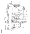
- FIG.2 is a plan view of the first embodiment of FIG.1
- FIG.3 is a sectional view of the first embodiment of FIG.1 along the center line of the rotor shaft of the high-pressure stage turbocharger.
- FIG. 4A is a side elevation showing the turbine housing of the high pressure stage exhaust turbocharger in the second embodiment of the invention
- FIG. 4B is a view in the direction of arrow Y in FIG.4A
- FIG.5 is a view in the direction of arrow W in FIG. 4A
- FIG. 6 is a partially sectional view of the air supply channel indicated by U in FIG.1 .
- reference numeral 1 is a high-pressure stage turbocharger having a high-pressure turbine 1a and a high-pressure compressor 1b connected to the turbine 1a by a high-pressure stage rotor shaft 3;
- 2 is a low-pressure stage turbocharger having a low-pressure turbine 2a and a low-pressure compressor 2b connected to the turbine by a low-pressure stage rotor shaft.
- Reference numeral 10 is a high-pressure turbine housing of the high-pressure stage turbocharger 1; 9 is a high-pressure compressor cover; 11 is an exhaust channel.
- Reference numeral 2s is a low-pressure turbine housing of the low-pressure stage turbocharger 2; 2t is a low-pressure compressor cover.
- Reference numeral 21 is an air supply channel connecting the low-pressure compressor cover 2t to the high-pressure compressor cover 9.
- the air supply channel 21 is detailed later.
- reference numeral 10 is a high-pressure turbine housing 10 of cast metal (may be of welded construction); 1a is a high-pressure turbine of radial flow type; 1b is a high-pressure compressor connected to the turbine 1a; 3 is a high-pressure stage rotor shaft connecting the turbine 1a and the compressor 1b; 9 is a high-pressure compressor made of cast metal; and 6 is a high-pressure stage bearing housing made of cast metal.
- Reference numeral 11 is an exhaust gas guide member made of cast metal, which is connected to a flange (10a indicates its flange face) of the high-pressure turbine housing 10 with the longitudinal center line of the channel coinciding the rotation axis M of the high-pressure turbine 1a by means of a plurality of bolts not shown in the drawing.
- the exhaust gas guide member 11 has a mounting flange 12 for connecting the low-pressure stage turbocharger 2b thereto.
- the mounting flange 12 extends in the direction parallel to the rotation axis M, and the low-pressure turbine housing 2s is connected directly to the flange 12 by means of a plurality of bolts(12z indicates a bolt hole) as shown in FIG.1 .
- Exhaust gas flowing out from the high-pressure turbine 1a is introduced to the entrance of the low-pressure turbine 2a passing through an exhaust gas passage 11s in the exhaust gas guide member 11 to the mounting flange of which is attached the low-pressure turbine 2a.
- the high-pressure compressor cover 9 has a compressor inlet passage 7 to which supply air is introduced from the low-pressure compressor 2b (see FIG. 1 ) via the air supply channel 21 and a bypass inlet passage 8a.
- a switching aperture 5c which is opened and closed by the compressor bypass valve device 5 is formed between the compressor inlet passage 7 and the bypass inlet passage 8a.
- the high-pressure compressor cover 9 has also a bypass outlet pipe part 8 to which the compressor bypass channel 12 is to be connected.
- the bypass outlet pipe part 8 is formed integral with the compressor cover 9 in a form extending in a direction perpendicular to the rotation axis M adjacent a case 53 attached to the compressor cover 9, the compressor bypass valve device 5 being attached to the case 53.
- the compressor bypass valve device 5 includes a compressor bypass valve 51 and an actuator 52, and the switching aperture 5c is closed or opened by allowing the compressor bypass valve 51 to seat on or depart from a valve seat 55 formed on the peripheral part of the switching aperture 5c by reciprocation motion of the actuator to shut off or communicate the compressor inlet passage 7 from or to the bypass inlet passage, thereby shutting off or communicating the compressor inlet passage 7 to or from a compressor bypass channel not shown in the drawing.
- a bypass outlet pipe part 8 is formed integral with the compressor cover 9 in a form extending in a direction perpendicular to the rotation axis M adjacent the compressor bypass valve device 5 installed to the compressor cover 9 as shown in FIG.3 .
- Reference numeral 15 is an EGR flange formed integral with the exhaust gas guide member 11. A part of exhaust gas flowed out from the outlet of the high pressure turbine 1a is extracted from the exhaust gas flowing in the passage 11s and introduced to a supply air inlet pipe(not shown) by a conduit(not shown) attached to the EGR flange as exhaust recirculation gas.
- reference numeral 103 is an exhaust manifold, which is formed integral with the high-pressure turbine housing 10 of the high-pressure stage turbocharger 1 and made by metal casting.
- the exhaust gas guide member 11 is connected to the flange face 10a of the flange 10b of the turbine housing 10 by a plurality of bolts not shown in the drawings with the longitudinal center line of the exhaust gas guide member 11 coinciding the rotation axis M of the high-pressure turbine 1a.
- Reference numeral 103a is a flange of the exhaust manifold 103.
- the flange face 103b of each flange 103a is perpendicular to the flange face 10a of the flange 10b of the high-pressure turbine housing 10, and the exhaust manifold is fixed to the engine via the flanges 103a by means of a plurality of bolts not shown in the drawings.
- Reference numeral 21 is an air supply channel bent to connect the low-pressure compressor cover 2t to the high-pressure compressor cover 9 and made of metal material, such as a steel pipe, and aluminum pipe, or a resin or hard rubber pipe having flexibility.
- the air supply channel 21 has an inlet flange 212 provided at its air inlet side.
- the flange 212 is fixed to the a flange 220 of the low-pressure compressor cover 2t by means of a plurality of bolts 213 with a seal ring 214 placed between the flanges.
- the air supply channel 21 has an outlet flange 215 provided at its air outlet side.
- the outlet flange 215 is fixed to a flange 9z of the high-pressure compressor cover 9 by means of a plurality of bolts 217.
- a protruded part 21y of the air supply channel 21 protruding from the flange 215 is received in a reception hole 9y of the high-pressure compressor cover 9 with an O-ring 216 placed between the protruding part 21y and the hole 9y for the purpose of air sealing.
- a stage control valve not shown in the drawings is closed or its opening is controlled, and an exhaust bypass valve device not shown in the drawings and the compressor bypass valve device 5 are closed.
- both the high-pressure turbine 1a of the high-pressure stage turbocharger 1 and the low-pressure turbine 2a of the low-pressure turbocharger 2 are driven by exhaust gas exhausted from the exhaust manifold 103.
- supply air pressurized by the low-pressure compressor 2b driven by the turbine 2a is further pressurized by the high-pressure compressor 1b driven by the high-pressure turbine 1a, then the pressurized supply air is cooled by an air cooler not shown in the drawings and supplied each of the cylinders of the engine as charge air for combustion in the cylinders.
- Supercharge pressure can be increased to increase engine output by performing two-stage supercharging like this in a low, middle speed operating range of the engine.
- the stage control valve and the compressor bypass valve device 5 are opened and the opening of the exhaust bypass valve device is controlled so that desired pressure of charge air is produced.
- the high-pressure turbine 1a, high-pressure compressor 1b, high-pressure bearing housing 6, high-pressure compressor cover 9, etc. are assembled to the high-pressure turbine housing 10 formed integral with the exhaust manifold 103 by casting or welding to compose the high-pressure stage turbocharger 1 using the flange face 10a of the flange 10b of the high-pressure turbine housing 10 as a reference plane, and the exhaust gas guide member 11 is attached to the flange 10b of by means of a plurality of bolts.
- the low-pressure stage turbocharger 2 comprising the low-pressure turbine 2a, low-pressure compressor 2b, low-pressure turbine casing 2s, low-pressure compressor cover 2t, etc. is assembled, and the low-pressure turbine housing 2s is fastened to the low-pressure turbine mounting flange 12 of the exhaust gas guide member 11 by means of a plurality of bolts (reference numeral 12z indicates a bolt hole).
- the high-pressure stage turbocharger 1 and low-pressure stage turbocharger 2 are connected via the exhaust gas guide member 11.
- the O-ring 216 is attached to the air outlet end parts 21y of the air supply channel 21, the end pars 21y is inserted into the reception hole 9y, and the outlet flange 215 of the air supply channel 21 fastened to the flange 9z of the high-pressure compressor cover 9 are fastened by means of bolts 217. Then, the seal ring 214 is attached to the flange 220 of the low-pressure compressor cover 2t, and the inlet flange 212 of the air supply channel 21 is fastened to the flange 220 of the low-pressure compressor cover 2t.
- the air supply pipe 21 is attached to connect between the high-pressure compressor cover 9 and the low-pressure compressor cover 2t in a state airtight connections are ensured.
- the high-pressure stage turbocharger 1 is assembled by attaching constituent parts of the high pressure stage turbocharger, including high pressure compressor cover 9, to the high-pressure turbine housing 10 which is formed integral with the exhaust manifold 103 by casting or welding, then the exhaust gas guide member 11 is attached to the high-pressure turbine housing 10, and then the low-pressure turbine housing 2s of the low-pressure stage turbocharger 2 is attached to the mounting flange 10 of the exhaust gas guide member 11, so the constituent parts of the high-pressure stage turbocharger 1 can be assembled easily by using the high-pressure turbine housing 10 formed integral with the exhaust manifold 103 as a reference plane, and the low-pressure stage turbocharger 2 is connected to the high-pressure stage turbocharger 1 without using any piping for connecting exhaust gas sides of the turbines such as an exhaust gas channel used in the prior art, and with only one air supply channel 21 connecting between the high-pressure compressor cover 9 and low-pressure compressor cover 2t, which connection being done at the last stage of assembling the turbochargers.
- connection of the turbine sides of the high-pressure stage turbocharger 1 and low-pressure stage turbocharger is facilitated resulting in decreased number of parts for the connection and decreased assembling man-hours as compared with the prior art.
- connection of the high-pressure and low-pressure stage turbochargers with piping is reduced to only one, i.e. the connection with the air supply channel 21, as compared with two piping connections of the prior two-stage exhaust turbocharger, bulk of the two-stage exhaust turbocharger device of the invention is reduced and mounting of an engine equipped with the two-stage exhaust turbocharger in a narrow engine room of a vehicle is facilitated.
- FIG.7 is a front view of second embodiment of the two-stage exhaust turbocharger in axial direction of the engine equipped with the turbocharger.
- the second embodiment relates to another method of attaching the two-stage exhaust turbocharger composed similar to that of the first embodiment to one side of an engine.
- the exhaust manifold 103 and the high-pressure turbine housing 10 are formed integral by casting or welding such that the flange faces 103b of the flanges 103a of the exhaust manifold 103 to attach the manifold to the engine is substantially perpendicular to the flange face 10a of the exhaust gas outlet flange 10b of the turbine housing 10 in the same way as is done in the first embodiment as shown in FIG.5 .
- the high-pressure turbine 1a, high-pressure compressor 1b, high-pressure bearing housing 6, high-pressure compressor cover 9, etc. are assembled to the high-pressure turbine housing 10 formed integral with the exhaust manifold 103 by casting or welding to compose the high-pressure stage turbocharger 1 using the flange face 10a of the flange 10b of the high-pressure turbine housing 10 as a reference plane, and the exhaust gas guide member 11 is attached to the flange 10b of by means of a plurality of bolts, in the same way as is done in the first embodiment.
- the exhaust gas guide member 11 is attached to the high-pressure turbine housing 10, and the exhaust manifold 103 attached with the high-pressure stage turbocharger 1 is attached to an exhaust gas outlet side of the engine by fastening the flanges 103a of the manifold 103 to the engine.
- the low-pressure stage turbocharger 2 comprising the low-pressure turbine 2a, low-pressure compressor 2b, low-pressure housing 2s, low-pressure compressor cover 2t, etc. is assembled and attached to the low-pressure mounting flange 12 of the exhaust gas guide member 11 by fastening the low-pressure turbine housing 2s to the flange 12 by means of a plurality of bolts.
- the two-stage turbocharger is attached to one side of the engine 100 in a state the low-pressure stage turbocharger 2 is located below the high-pressure stage turbocharger 1 as shown in FIG.7 .
- the O-ring 216 is attached to the air outlet end parts 21y of the air supply channel 21, the end pars 21y is inserted into the reception hole 9y, and the outlet flange 215 of the air supply channel 21 fastened to the flange 9z of the high-pressure compressor cover 9 are fastened by means of bolts 217. Then, the seal ring 214 is attached to the flange 220 of the low-pressure compressor cover 2t, and the inlet flange 212 of the air supply channel 21 is fastened to the flange 220 of the low-pressure compressor cover 2t, in the same way as is done in the first embodiment as shown in FIG.6 .
- the air supply pipe 21 is attached to connect between the high-pressure compressor cover 9 and the low-pressure compressor cover 2t in a state airtight connections are ensured.
- the exhaust manifold 103 attached with the high-pressure stage turbocharger 1 is fastened to the engine and then the low-pressure stage turbocharger 2 is attached to the engine, so a relatively light sub-assembly of the exhaust manifold 103 and the relatively small high-pressure stage turbocharger 1 is attached to one side of the engine and then the relatively large and heavy low-pressure stage turbocharger 2 is attached to the sub-assembly already attached to the engine, the attaching operation is facilitated, resulting decreased man-hours of attaching the two-stage turbocharger to the engine.
- a method of manufacturing a multistage exhaust turbocharger decreased in the number of parts for connecting the high-pressure and low-pressure stage turbochargers of the multistage exhaust turbocharger can be provided, and an engine equipped with the multistage exhaust turbocharger reduced in bulk and easily mountable in a narrow engine room of a vehicle can be obtained.
Landscapes
- Engineering & Computer Science (AREA)
- Mechanical Engineering (AREA)
- General Engineering & Computer Science (AREA)
- Chemical & Material Sciences (AREA)
- Combustion & Propulsion (AREA)
- Chemical Kinetics & Catalysis (AREA)
- General Chemical & Material Sciences (AREA)
- Supercharger (AREA)
- Exhaust Silencers (AREA)
Applications Claiming Priority (2)
| Application Number | Priority Date | Filing Date | Title |
|---|---|---|---|
| JP2006218095A JP4365840B2 (ja) | 2006-08-10 | 2006-08-10 | 多段過給式排気ターボ過給機の製造方法 |
| PCT/JP2007/065677 WO2008018577A1 (fr) | 2006-08-10 | 2007-08-03 | Procédé de fabrication d'un turbocompresseur à gaz d'échappement à suralimentation à plusieurs étages |
Publications (3)
| Publication Number | Publication Date |
|---|---|
| EP2050940A1 true EP2050940A1 (de) | 2009-04-22 |
| EP2050940A4 EP2050940A4 (de) | 2015-03-11 |
| EP2050940B1 EP2050940B1 (de) | 2019-04-10 |
Family
ID=39033105
Family Applications (1)
| Application Number | Title | Priority Date | Filing Date |
|---|---|---|---|
| EP07792323.3A Active EP2050940B1 (de) | 2006-08-10 | 2007-08-03 | Verfahren zur herstellung, dem zusammenbau und der befestigung eines mehrstufigen abgasturboladers |
Country Status (6)
| Country | Link |
|---|---|
| US (1) | US8387243B2 (de) |
| EP (1) | EP2050940B1 (de) |
| JP (1) | JP4365840B2 (de) |
| KR (1) | KR100934596B1 (de) |
| CN (1) | CN101341319B (de) |
| WO (1) | WO2008018577A1 (de) |
Cited By (10)
| Publication number | Priority date | Publication date | Assignee | Title |
|---|---|---|---|---|
| US20100095672A1 (en) * | 2007-10-12 | 2010-04-22 | Mitsubishi Heavy Industries, Ltd. | Two-stage supercharging exhaust turbocharger |
| FR2945577A1 (fr) * | 2009-05-15 | 2010-11-19 | Peugeot Citroen Automobiles Sa | Boitier de derivation et systeme de suralimentation comportant un tel boitier |
| DE102009052167A1 (de) * | 2009-11-06 | 2011-05-12 | Mtu Friedrichshafen Gmbh | Rohranordnung |
| US7966816B1 (en) | 2010-01-11 | 2011-06-28 | Ford Global Technologies | Turbocharged internal combustion engine |
| CN102767622A (zh) * | 2012-07-04 | 2012-11-07 | 联优机械(常熟)有限公司 | 透平膨胀机的外功输出过渡连接装置 |
| EP2634393A2 (de) * | 2012-03-01 | 2013-09-04 | MAN Truck & Bus Österreich AG | Funktionsmodul mit einem Abgasturbolader und einem Abgaskrümmer |
| EP2789801A1 (de) * | 2013-04-09 | 2014-10-15 | ABB Turbo Systems AG | Gehäuse eines Radialverdichters |
| EP3441588A4 (de) * | 2016-04-08 | 2019-03-20 | Yanmar Co., Ltd. | Motorvorrichtung |
| DE102013223282B4 (de) | 2012-11-21 | 2022-10-13 | Ihi Corp. | Turbolader |
| DE102014217333B4 (de) | 2013-08-29 | 2023-01-19 | Honda Motor Co., Ltd. | Mehrstufiges Turboladersystem für einen Verbrennungsmotor |
Families Citing this family (21)
| Publication number | Priority date | Publication date | Assignee | Title |
|---|---|---|---|---|
| GB2446146B (en) * | 2007-01-31 | 2009-11-18 | Gm Global Tech Operations Inc | Arrangement of a two stage turbocharger system for an internal combustion engine |
| BE1018159A5 (fr) | 2008-05-23 | 2010-06-01 | Gerhard Schmitz | Moteur a combustion interne suralimente par turbo-compresseur. |
| KR100986069B1 (ko) * | 2008-06-12 | 2010-10-07 | 기아자동차주식회사 | 배기 매니 폴드 |
| DE102009030482A1 (de) * | 2009-06-24 | 2011-03-24 | Benteler Automobiltechnik Gmbh | Abgasbaugruppe |
| US8813492B2 (en) * | 2009-10-14 | 2014-08-26 | Hansen Engine Corporation | Internal combustion engine and supercharger |
| FI20105894A (fi) * | 2010-08-30 | 2012-03-01 | Waertsilae Finland Oy | Pakokaasumoduuli ja polttomoottori |
| KR101846459B1 (ko) * | 2010-10-11 | 2018-05-18 | 보르그워너 인코퍼레이티드 | 배기가스 터보차저 |
| US9217370B2 (en) | 2011-02-18 | 2015-12-22 | Dynamo Micropower Corporation | Fluid flow devices with vertically simple geometry and methods of making the same |
| DE102011079495A1 (de) | 2011-07-20 | 2013-01-24 | Zf Friedrichshafen Ag | Vorrichtung zum Betätigen einer reibschlüssigen Wandlerüberbrückungskupplung eines hydrodynamischen Drehmomentwandlers |
| JP5926520B2 (ja) * | 2011-09-15 | 2016-05-25 | 日野自動車株式会社 | 二段過給システム及び該二段過給システムのエンジン組付方法 |
| CN102434283A (zh) * | 2011-11-09 | 2012-05-02 | 无锡康明斯涡轮增压技术有限公司 | 两级增压废气涡轮增压器一体化低压级涡轮壳结构 |
| FR3000134B1 (fr) * | 2012-12-26 | 2014-12-05 | Renault Sa | Organe d'echappement pour moteur a combustion interne |
| WO2014199812A1 (ja) * | 2013-06-11 | 2014-12-18 | ヤンマー株式会社 | エンジン |
| KR101526739B1 (ko) * | 2013-12-16 | 2015-06-05 | 현대자동차주식회사 | 배기매니폴드 일체형 고압터빈 하우징 및 이를 구비한 2단 터보장치 |
| US10030580B2 (en) | 2014-04-11 | 2018-07-24 | Dynamo Micropower Corporation | Micro gas turbine systems and uses thereof |
| KR101953050B1 (ko) * | 2015-02-27 | 2019-02-27 | 미츠비시 쥬고교 가부시키가이샤 | 내연 기관의 제어 장치 및 이것을 구비한 선박 그리고 내연 기관의 운전 방법 |
| DE102016123249A1 (de) * | 2016-12-01 | 2018-06-07 | Man Diesel & Turbo Se | Turbolader |
| CN107514308B (zh) * | 2017-09-21 | 2022-03-15 | 西峡县内燃机进排气管有限责任公司 | 高端发动机排气歧管及其制造方法 |
| US11668230B2 (en) | 2021-01-28 | 2023-06-06 | Caterpillar Inc. | Annular disk for turbocharger speed control |
| US11492924B1 (en) * | 2021-04-26 | 2022-11-08 | General Electric Company Polska sp. z o.o | Embedded electric machine cooling |
| US20230095482A1 (en) * | 2021-09-26 | 2023-03-30 | Garrett Transportation I Inc. | Turbocharger turbine housing |
Family Cites Families (13)
| Publication number | Priority date | Publication date | Assignee | Title |
|---|---|---|---|---|
| US4294073A (en) * | 1979-10-05 | 1981-10-13 | Cummins Engine Company, Inc. | Integral turbine housing and exhaust collector section |
| JPS5982526A (ja) | 1982-10-29 | 1984-05-12 | Hino Motors Ltd | 内燃機関の過給装置 |
| US4783959A (en) * | 1987-09-22 | 1988-11-15 | Arvin Industries, Inc. | Exhaust processor assembly |
| JPH0441957A (ja) * | 1990-06-02 | 1992-02-12 | Toyota Motor Corp | 過給希薄燃焼ガソリン内燃機関の空燃比制御装置 |
| WO1999054607A1 (en) | 1998-04-16 | 1999-10-28 | 3K-Warner Turbosystems Gmbh | Turbocharged internal combustion engine |
| JP2000199427A (ja) * | 1998-12-28 | 2000-07-18 | Hitachi Metals Ltd | タ―ボチャ―ジャ用タ―ビンハウジングを鋳造一体化した排気マニホ―ルド |
| DE10014755A1 (de) * | 2000-03-24 | 2001-10-04 | Bayerische Motoren Werke Ag | Brennkraftmaschine mit einer zweistufigen, schaltbaren Abgas-Turbolader-Anordnung |
| DE10019774A1 (de) | 2000-04-20 | 2001-11-22 | Daimler Chrysler Ag | Turbolader-Einrichtung für eine Brennkraftmaschine |
| JP2003221639A (ja) * | 2002-01-31 | 2003-08-08 | Aisin Takaoka Ltd | タービンハウジング一体型排気マニホルド及びその製造方法 |
| SE525218C2 (sv) * | 2003-05-15 | 2004-12-28 | Volvo Lastvagnar Ab | Turboladdarsystem för en förbränningsmotor innefattande två seriellt och väsentligen koncentriskt med rotationsaxlarna placerade turboenheter |
| DE50303860D1 (de) * | 2003-11-28 | 2006-07-27 | Borgwarner Inc | Gehäuse für Turbolader |
| JP2005344638A (ja) * | 2004-06-03 | 2005-12-15 | Toyota Motor Corp | 内燃機関の制御装置 |
| CN100535407C (zh) * | 2005-05-12 | 2009-09-02 | 上海交通大学 | 大小涡轮增压器串并联可调高增压系统 |
-
2006
- 2006-08-10 JP JP2006218095A patent/JP4365840B2/ja not_active Expired - Fee Related
-
2007
- 2007-08-03 US US11/989,284 patent/US8387243B2/en active Active
- 2007-08-03 WO PCT/JP2007/065677 patent/WO2008018577A1/ja active Application Filing
- 2007-08-03 CN CN2007800007831A patent/CN101341319B/zh active Active
- 2007-08-03 KR KR1020087002657A patent/KR100934596B1/ko not_active IP Right Cessation
- 2007-08-03 EP EP07792323.3A patent/EP2050940B1/de active Active
Cited By (19)
| Publication number | Priority date | Publication date | Assignee | Title |
|---|---|---|---|---|
| US20100095672A1 (en) * | 2007-10-12 | 2010-04-22 | Mitsubishi Heavy Industries, Ltd. | Two-stage supercharging exhaust turbocharger |
| US8844285B2 (en) * | 2007-10-12 | 2014-09-30 | Mitsubishi Heavy Industries, Ltd. | Two-stage supercharging exhaust turbocharger |
| FR2945577A1 (fr) * | 2009-05-15 | 2010-11-19 | Peugeot Citroen Automobiles Sa | Boitier de derivation et systeme de suralimentation comportant un tel boitier |
| DE102009052167A1 (de) * | 2009-11-06 | 2011-05-12 | Mtu Friedrichshafen Gmbh | Rohranordnung |
| US9016061B2 (en) | 2009-11-06 | 2015-04-28 | Mtu Friedrichshafen Gmbh | Pipe arrangement |
| US7966816B1 (en) | 2010-01-11 | 2011-06-28 | Ford Global Technologies | Turbocharged internal combustion engine |
| EP2634393A3 (de) * | 2012-03-01 | 2015-04-22 | MAN Truck & Bus Österreich AG | Funktionsmodul mit einem Abgasturbolader und einem Abgaskrümmer |
| EP2634393A2 (de) * | 2012-03-01 | 2013-09-04 | MAN Truck & Bus Österreich AG | Funktionsmodul mit einem Abgasturbolader und einem Abgaskrümmer |
| CN102767622A (zh) * | 2012-07-04 | 2012-11-07 | 联优机械(常熟)有限公司 | 透平膨胀机的外功输出过渡连接装置 |
| CN102767622B (zh) * | 2012-07-04 | 2014-10-29 | 联优机械(常熟)有限公司 | 透平膨胀机的外功输出过渡连接装置 |
| DE102013223282B4 (de) | 2012-11-21 | 2022-10-13 | Ihi Corp. | Turbolader |
| JP2014202214A (ja) * | 2013-04-09 | 2014-10-27 | アーベーベー ターボ システムズ アクチエンゲゼルシャフト | 遠心コンプレッサのハウジング |
| CN104100571A (zh) * | 2013-04-09 | 2014-10-15 | Abb涡轮系统有限公司 | 径流式压缩机的壳体 |
| EP2789801A1 (de) * | 2013-04-09 | 2014-10-15 | ABB Turbo Systems AG | Gehäuse eines Radialverdichters |
| US9541095B2 (en) | 2013-04-09 | 2017-01-10 | Abb Turbo Systems Ag | Housing of a radial compressor |
| CN104100571B (zh) * | 2013-04-09 | 2017-03-22 | Abb涡轮系统有限公司 | 径流式压缩机的壳体 |
| DE102014217333B4 (de) | 2013-08-29 | 2023-01-19 | Honda Motor Co., Ltd. | Mehrstufiges Turboladersystem für einen Verbrennungsmotor |
| EP3441588A4 (de) * | 2016-04-08 | 2019-03-20 | Yanmar Co., Ltd. | Motorvorrichtung |
| US10781743B2 (en) | 2016-04-08 | 2020-09-22 | Yanmar Power Technology Co., Ltd. | Engine device |
Also Published As
| Publication number | Publication date |
|---|---|
| JP4365840B2 (ja) | 2009-11-18 |
| EP2050940A4 (de) | 2015-03-11 |
| KR100934596B1 (ko) | 2009-12-31 |
| KR20080033327A (ko) | 2008-04-16 |
| US20100126016A1 (en) | 2010-05-27 |
| CN101341319B (zh) | 2011-02-09 |
| WO2008018577A1 (fr) | 2008-02-14 |
| US8387243B2 (en) | 2013-03-05 |
| EP2050940B1 (de) | 2019-04-10 |
| CN101341319A (zh) | 2009-01-07 |
| JP2008038870A (ja) | 2008-02-21 |
Similar Documents
| Publication | Publication Date | Title |
|---|---|---|
| EP2050940B1 (de) | Verfahren zur herstellung, dem zusammenbau und der befestigung eines mehrstufigen abgasturboladers | |
| EP2050939B1 (de) | Mehrstufiger abgasturbolader | |
| US7360362B2 (en) | Two-stage turbocharger system with integrated exhaust manifold and bypass assembly | |
| EP2199566B1 (de) | Zweistufiger turbolader | |
| US9932843B2 (en) | Double flow turbine housing turbocharger | |
| CN102042076B (zh) | 涡轮增压器和具有该增压器的空气引入系统及其使用方法 | |
| JP5390605B2 (ja) | 内燃機関のエグゾーストターボチャージャ用タービンハウジング | |
| US9500121B2 (en) | Turbocharger | |
| US10502219B2 (en) | Supercharging device for a combustion engine | |
| JP5115648B2 (ja) | 2ターボ過給システムにおけるタービンハウジングの取付構造 | |
| CN116357408A (zh) | 双涡管涡轮壳体 | |
| KR20090110331A (ko) | 2단 과급식 배기 터보 과급기 |
Legal Events
| Date | Code | Title | Description |
|---|---|---|---|
| PUAI | Public reference made under article 153(3) epc to a published international application that has entered the european phase |
Free format text: ORIGINAL CODE: 0009012 |
|
| 17P | Request for examination filed |
Effective date: 20080131 |
|
| AK | Designated contracting states |
Kind code of ref document: A1 Designated state(s): AT BE BG CH CY CZ DE DK EE ES FI FR GB GR HU IE IS IT LI LT LU LV MC MT NL PL PT RO SE SI SK TR |
|
| AX | Request for extension of the european patent |
Extension state: AL BA HR MK RS |
|
| RBV | Designated contracting states (corrected) |
Designated state(s): DE FR GB IT NL |
|
| DAX | Request for extension of the european patent (deleted) | ||
| A4 | Supplementary search report drawn up and despatched |
Effective date: 20150205 |
|
| RIC1 | Information provided on ipc code assigned before grant |
Ipc: F02B 39/00 20060101AFI20150304BHEP Ipc: F02B 37/013 20060101ALI20150304BHEP Ipc: F01N 13/18 20100101ALI20150304BHEP Ipc: F01N 13/10 20100101ALI20150304BHEP |
|
| 17Q | First examination report despatched |
Effective date: 20180202 |
|
| GRAP | Despatch of communication of intention to grant a patent |
Free format text: ORIGINAL CODE: EPIDOSNIGR1 |
|
| INTG | Intention to grant announced |
Effective date: 20180706 |
|
| RAP1 | Party data changed (applicant data changed or rights of an application transferred) |
Owner name: MITSUBISHI HEAVY INDUSTRIES ENGINE & TURBOCHARGER, |
|
| GRAJ | Information related to disapproval of communication of intention to grant by the applicant or resumption of examination proceedings by the epo deleted |
Free format text: ORIGINAL CODE: EPIDOSDIGR1 |
|
| GRAP | Despatch of communication of intention to grant a patent |
Free format text: ORIGINAL CODE: EPIDOSNIGR1 |
|
| INTG | Intention to grant announced |
Effective date: 20181115 |
|
| RIC1 | Information provided on ipc code assigned before grant |
Ipc: F02B 39/00 20060101AFI20150304BHEP Ipc: F01N 13/10 20100101ALI20150304BHEP Ipc: F02B 37/013 20060101ALI20150304BHEP Ipc: F01N 13/18 20100101ALI20150304BHEP |
|
| RIC1 | Information provided on ipc code assigned before grant |
Ipc: F01N 13/10 20100101ALI20150304BHEP Ipc: F01N 13/18 20100101ALI20150304BHEP Ipc: F02B 39/00 20060101AFI20150304BHEP Ipc: F02B 37/013 20060101ALI20150304BHEP |
|
| GRAS | Grant fee paid |
Free format text: ORIGINAL CODE: EPIDOSNIGR3 |
|
| GRAA | (expected) grant |
Free format text: ORIGINAL CODE: 0009210 |
|
| AK | Designated contracting states |
Kind code of ref document: B1 Designated state(s): DE FR GB IT NL |
|
| REG | Reference to a national code |
Ref country code: GB Ref legal event code: FG4D |
|
| REG | Reference to a national code |
Ref country code: DE Ref legal event code: R096 Ref document number: 602007058081 Country of ref document: DE |
|
| REG | Reference to a national code |
Ref country code: NL Ref legal event code: FP |
|
| REG | Reference to a national code |
Ref country code: DE Ref legal event code: R097 Ref document number: 602007058081 Country of ref document: DE |
|
| PLBE | No opposition filed within time limit |
Free format text: ORIGINAL CODE: 0009261 |
|
| STAA | Information on the status of an ep patent application or granted ep patent |
Free format text: STATUS: NO OPPOSITION FILED WITHIN TIME LIMIT |
|
| PG25 | Lapsed in a contracting state [announced via postgrant information from national office to epo] |
Ref country code: IT Free format text: LAPSE BECAUSE OF FAILURE TO SUBMIT A TRANSLATION OF THE DESCRIPTION OR TO PAY THE FEE WITHIN THE PRESCRIBED TIME-LIMIT Effective date: 20190410 |
|
| 26N | No opposition filed |
Effective date: 20200113 |
|
| PGFP | Annual fee paid to national office [announced via postgrant information from national office to epo] |
Ref country code: NL Payment date: 20200715 Year of fee payment: 14 |
|
| PGFP | Annual fee paid to national office [announced via postgrant information from national office to epo] |
Ref country code: GB Payment date: 20200722 Year of fee payment: 14 Ref country code: FR Payment date: 20200715 Year of fee payment: 14 |
|
| REG | Reference to a national code |
Ref country code: NL Ref legal event code: MM Effective date: 20210901 |
|
| GBPC | Gb: european patent ceased through non-payment of renewal fee |
Effective date: 20210803 |
|
| PG25 | Lapsed in a contracting state [announced via postgrant information from national office to epo] |
Ref country code: NL Free format text: LAPSE BECAUSE OF NON-PAYMENT OF DUE FEES Effective date: 20210901 |
|
| PG25 | Lapsed in a contracting state [announced via postgrant information from national office to epo] |
Ref country code: GB Free format text: LAPSE BECAUSE OF NON-PAYMENT OF DUE FEES Effective date: 20210803 Ref country code: FR Free format text: LAPSE BECAUSE OF NON-PAYMENT OF DUE FEES Effective date: 20210831 |
|
| REG | Reference to a national code |
Ref country code: DE Ref legal event code: R082 Ref document number: 602007058081 Country of ref document: DE Representative=s name: CBDL PATENTANWAELTE GBR, DE |
|
| PGFP | Annual fee paid to national office [announced via postgrant information from national office to epo] |
Ref country code: DE Payment date: 20230627 Year of fee payment: 17 |