EP2634393A2 - Funktionsmodul mit einem Abgasturbolader und einem Abgaskrümmer - Google Patents
Funktionsmodul mit einem Abgasturbolader und einem Abgaskrümmer Download PDFInfo
- Publication number
- EP2634393A2 EP2634393A2 EP12007015.6A EP12007015A EP2634393A2 EP 2634393 A2 EP2634393 A2 EP 2634393A2 EP 12007015 A EP12007015 A EP 12007015A EP 2634393 A2 EP2634393 A2 EP 2634393A2
- Authority
- EP
- European Patent Office
- Prior art keywords
- exhaust gas
- exhaust
- module according
- exhaust manifold
- function module
- Prior art date
- Legal status (The legal status is an assumption and is not a legal conclusion. Google has not performed a legal analysis and makes no representation as to the accuracy of the status listed.)
- Granted
Links
- 238000002485 combustion reaction Methods 0.000 claims abstract description 28
- 230000000694 effects Effects 0.000 claims abstract description 3
- 239000007789 gas Substances 0.000 claims description 67
- 238000005266 casting Methods 0.000 claims description 6
- 239000000463 material Substances 0.000 claims description 2
- 238000011144 upstream manufacturing Methods 0.000 claims description 2
- 238000005516 engineering process Methods 0.000 description 3
- 238000009434 installation Methods 0.000 description 2
- 238000004519 manufacturing process Methods 0.000 description 2
- 238000012986 modification Methods 0.000 description 2
- 230000004048 modification Effects 0.000 description 2
- 238000000926 separation method Methods 0.000 description 2
- 238000012360 testing method Methods 0.000 description 2
- 238000010276 construction Methods 0.000 description 1
- 238000001816 cooling Methods 0.000 description 1
- 230000001419 dependent effect Effects 0.000 description 1
- 230000002349 favourable effect Effects 0.000 description 1
- 238000000746 purification Methods 0.000 description 1
- 230000005855 radiation Effects 0.000 description 1
- 230000001052 transient effect Effects 0.000 description 1
Images


Classifications
-
- F—MECHANICAL ENGINEERING; LIGHTING; HEATING; WEAPONS; BLASTING
- F02—COMBUSTION ENGINES; HOT-GAS OR COMBUSTION-PRODUCT ENGINE PLANTS
- F02B—INTERNAL-COMBUSTION PISTON ENGINES; COMBUSTION ENGINES IN GENERAL
- F02B37/00—Engines characterised by provision of pumps driven at least for part of the time by exhaust
- F02B37/12—Control of the pumps
- F02B37/18—Control of the pumps by bypassing exhaust from the inlet to the outlet of turbine or to the atmosphere
- F02B37/183—Arrangements of bypass valves or actuators therefor
-
- F—MECHANICAL ENGINEERING; LIGHTING; HEATING; WEAPONS; BLASTING
- F01—MACHINES OR ENGINES IN GENERAL; ENGINE PLANTS IN GENERAL; STEAM ENGINES
- F01N—GAS-FLOW SILENCERS OR EXHAUST APPARATUS FOR MACHINES OR ENGINES IN GENERAL; GAS-FLOW SILENCERS OR EXHAUST APPARATUS FOR INTERNAL COMBUSTION ENGINES
- F01N13/00—Exhaust or silencing apparatus characterised by constructional features ; Exhaust or silencing apparatus, or parts thereof, having pertinent characteristics not provided for in, or of interest apart from, groups F01N1/00 - F01N5/00, F01N9/00, F01N11/00
- F01N13/08—Other arrangements or adaptations of exhaust conduits
- F01N13/10—Other arrangements or adaptations of exhaust conduits of exhaust manifolds
-
- F—MECHANICAL ENGINEERING; LIGHTING; HEATING; WEAPONS; BLASTING
- F02—COMBUSTION ENGINES; HOT-GAS OR COMBUSTION-PRODUCT ENGINE PLANTS
- F02B—INTERNAL-COMBUSTION PISTON ENGINES; COMBUSTION ENGINES IN GENERAL
- F02B37/00—Engines characterised by provision of pumps driven at least for part of the time by exhaust
- F02B37/12—Control of the pumps
- F02B37/16—Control of the pumps by bypassing charging air
- F02B37/168—Control of the pumps by bypassing charging air into the exhaust conduit
-
- F—MECHANICAL ENGINEERING; LIGHTING; HEATING; WEAPONS; BLASTING
- F02—COMBUSTION ENGINES; HOT-GAS OR COMBUSTION-PRODUCT ENGINE PLANTS
- F02B—INTERNAL-COMBUSTION PISTON ENGINES; COMBUSTION ENGINES IN GENERAL
- F02B37/00—Engines characterised by provision of pumps driven at least for part of the time by exhaust
- F02B37/12—Control of the pumps
- F02B37/22—Control of the pumps by varying cross-section of exhaust passages or air passages, e.g. by throttling turbine inlets or outlets or by varying effective number of guide conduits
-
- F—MECHANICAL ENGINEERING; LIGHTING; HEATING; WEAPONS; BLASTING
- F02—COMBUSTION ENGINES; HOT-GAS OR COMBUSTION-PRODUCT ENGINE PLANTS
- F02M—SUPPLYING COMBUSTION ENGINES IN GENERAL WITH COMBUSTIBLE MIXTURES OR CONSTITUENTS THEREOF
- F02M26/00—Engine-pertinent apparatus for adding exhaust gases to combustion-air, main fuel or fuel-air mixture, e.g. by exhaust gas recirculation [EGR] systems
- F02M26/02—EGR systems specially adapted for supercharged engines
- F02M26/09—Constructional details, e.g. structural combinations of EGR systems and supercharger systems; Arrangement of the EGR and supercharger systems with respect to the engine
- F02M26/10—Constructional details, e.g. structural combinations of EGR systems and supercharger systems; Arrangement of the EGR and supercharger systems with respect to the engine having means to increase the pressure difference between the exhaust and intake system, e.g. venturis, variable geometry turbines, check valves using pressure pulsations or throttles in the air intake or exhaust system
-
- F—MECHANICAL ENGINEERING; LIGHTING; HEATING; WEAPONS; BLASTING
- F02—COMBUSTION ENGINES; HOT-GAS OR COMBUSTION-PRODUCT ENGINE PLANTS
- F02M—SUPPLYING COMBUSTION ENGINES IN GENERAL WITH COMBUSTIBLE MIXTURES OR CONSTITUENTS THEREOF
- F02M26/00—Engine-pertinent apparatus for adding exhaust gases to combustion-air, main fuel or fuel-air mixture, e.g. by exhaust gas recirculation [EGR] systems
- F02M26/13—Arrangement or layout of EGR passages, e.g. in relation to specific engine parts or for incorporation of accessories
- F02M26/14—Arrangement or layout of EGR passages, e.g. in relation to specific engine parts or for incorporation of accessories in relation to the exhaust system
- F02M26/16—Arrangement or layout of EGR passages, e.g. in relation to specific engine parts or for incorporation of accessories in relation to the exhaust system with EGR valves located at or near the connection to the exhaust system
-
- F—MECHANICAL ENGINEERING; LIGHTING; HEATING; WEAPONS; BLASTING
- F02—COMBUSTION ENGINES; HOT-GAS OR COMBUSTION-PRODUCT ENGINE PLANTS
- F02M—SUPPLYING COMBUSTION ENGINES IN GENERAL WITH COMBUSTIBLE MIXTURES OR CONSTITUENTS THEREOF
- F02M26/00—Engine-pertinent apparatus for adding exhaust gases to combustion-air, main fuel or fuel-air mixture, e.g. by exhaust gas recirculation [EGR] systems
- F02M26/65—Constructional details of EGR valves
- F02M26/70—Flap valves; Rotary valves; Sliding valves; Resilient valves
-
- F—MECHANICAL ENGINEERING; LIGHTING; HEATING; WEAPONS; BLASTING
- F02—COMBUSTION ENGINES; HOT-GAS OR COMBUSTION-PRODUCT ENGINE PLANTS
- F02B—INTERNAL-COMBUSTION PISTON ENGINES; COMBUSTION ENGINES IN GENERAL
- F02B37/00—Engines characterised by provision of pumps driven at least for part of the time by exhaust
-
- F—MECHANICAL ENGINEERING; LIGHTING; HEATING; WEAPONS; BLASTING
- F02—COMBUSTION ENGINES; HOT-GAS OR COMBUSTION-PRODUCT ENGINE PLANTS
- F02D—CONTROLLING COMBUSTION ENGINES
- F02D9/00—Controlling engines by throttling air or fuel-and-air induction conduits or exhaust conduits
- F02D9/04—Controlling engines by throttling air or fuel-and-air induction conduits or exhaust conduits concerning exhaust conduits
- F02D9/06—Exhaust brakes
-
- F—MECHANICAL ENGINEERING; LIGHTING; HEATING; WEAPONS; BLASTING
- F02—COMBUSTION ENGINES; HOT-GAS OR COMBUSTION-PRODUCT ENGINE PLANTS
- F02M—SUPPLYING COMBUSTION ENGINES IN GENERAL WITH COMBUSTIBLE MIXTURES OR CONSTITUENTS THEREOF
- F02M26/00—Engine-pertinent apparatus for adding exhaust gases to combustion-air, main fuel or fuel-air mixture, e.g. by exhaust gas recirculation [EGR] systems
- F02M26/02—EGR systems specially adapted for supercharged engines
- F02M26/04—EGR systems specially adapted for supercharged engines with a single turbocharger
- F02M26/05—High pressure loops, i.e. wherein recirculated exhaust gas is taken out from the exhaust system upstream of the turbine and reintroduced into the intake system downstream of the compressor
-
- Y—GENERAL TAGGING OF NEW TECHNOLOGICAL DEVELOPMENTS; GENERAL TAGGING OF CROSS-SECTIONAL TECHNOLOGIES SPANNING OVER SEVERAL SECTIONS OF THE IPC; TECHNICAL SUBJECTS COVERED BY FORMER USPC CROSS-REFERENCE ART COLLECTIONS [XRACs] AND DIGESTS
- Y02—TECHNOLOGIES OR APPLICATIONS FOR MITIGATION OR ADAPTATION AGAINST CLIMATE CHANGE
- Y02T—CLIMATE CHANGE MITIGATION TECHNOLOGIES RELATED TO TRANSPORTATION
- Y02T10/00—Road transport of goods or passengers
- Y02T10/10—Internal combustion engine [ICE] based vehicles
- Y02T10/12—Improving ICE efficiencies
Definitions
- the present invention relates to a functional module with an exhaust gas turbocharger and an exhaust manifold for a turbo-charged internal combustion engine in motor vehicles according to the preamble of patent claim 1.
- the exhaust gas turbocharger or its exhaust gas turbine if structurally possible directly to the exhaust manifold of the engine to avoid efficiency losses and to ensure a fast response of the turbocharger in transient operation.
- devices for boost pressure control by means of a bypass valve and possibly for exhaust gas recirculation into the intake system of the internal combustion engine are common to meet in particular specifications for exhaust gas purification.
- dampers in the exhaust system to achieve an enhanced engine braking effect in overrun operation of the motor vehicle are used.
- the object of the invention is to propose a functional module of the generic type, which is low in terms of production and structurally simple.
- the brake flap of the engine brake device, the bypass flap of the boost pressure control and possibly the exhaust gas recirculation valve of the exhaust gas recirculation device are integrated into a functional module.
- the functional module according to the invention represents an easily manageable, compact and functionally integrated assembly unit, which is to be connected only to the corresponding, electronic control units and which enables or can be adjusted in advance to relevant system diagnoses. The cultivation of the internal combustion engine is then quickly and easily carried out.
- actuators or actuators electric and / or pneumatic and / or hydraulic
- the brake flap and / or the bypass valve and possibly the return valve are already attached to the functional module.
- a support bracket may be provided on the exhaust gas turbocharger, which at the same time advantageously forms a heat shield on the exhaust manifold.
- the heat shield avoids in particular excessive heat radiation and ambient temperatures in the engine compartment of the motor vehicle and may be at least partially separated or spaced by an insulating air gap from the exhaust manifold.
- the actuators for the exhaust gas recirculation and the brake flap in the installation position of the function module can be easily accessible positioned on the top and fixed to the support bracket, whereby testing or adjustment work can be facilitated.
- the exhaust gas recirculation valve may be formed in a preferred embodiment by a simple, controllable in any intermediate positions throttle valve, which is arranged in a formed on the exhaust manifold connecting piece for an exhaust gas recirculation line.
- the brake flap of the engine brake device can be used near the exhaust gas turbine of the exhaust gas turbocharger in a line section of the exhaust manifold.
- the brake flap could also be positioned directly inside the housing of the exhaust gas turbine, which, however, would possibly require separate, structural modifications there.
- the bypass flap for the boost pressure control can basically be arranged in the exhaust gas turbocharger in a bypass line connecting the outgoing charge pressure line of the compressor to the exhaust gas turbine.
- the housing of the exhaust gas turbine and the exhaust manifold can each be made in one piece as a casting and connected to each other via terminal areas, in particular connecting flanges or fastened together, for example by at least one screw.
- the housing of the exhaust gas turbine and the exhaust manifold may be formed by a one-piece, in particular material and / or one piece, manufactured component, in particular a cast component, in particular be made as a whole in one piece.
- the housing of the exhaust gas turbine and the exhaust manifold can also run in two parts and cast together such that the parting surface of the two parts is approximately along the central axis of the pipes integrated in the exhaust manifold.
- the exhaust manifold would then be double-shelled with a reaching into the housing of the exhaust gas turbine, flat separation surface.
- the two parts can then be screwed together, for example, or possibly also welded together.
- the exhaust manifold may also be integrally formed, e.g. be designed and manufactured as a one-piece casting. Alternatively, however, the exhaust manifold can also be designed in several parts, wherein the individual manifold parts are then firmly connected to each other in the assembled state and at least one of the manifold parts forms part of the functional module according to the invention.
- another line section may be provided, e.g. be poured over which the exhaust gases further cylinder of the internal combustion engine can be introduced.
- the functional module can thus be used for internal combustion engines of different numbers of cylinders, wherein the line section produces the necessary compatibility.
- the exhaust gas turbocharger may be a high-pressure turbocharger a Registeraufladung the internal combustion engine with a high-pressure supercharger and a downstream exhaust low-pressure supercharger.
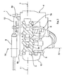
- Fig. 1 and 2 show in three-dimensional view of a functional module 1 for a turbo-charged inline internal combustion engine with a cast housing having exhaust gas turbocharger 2 (unless otherwise described known type) and an exhaust manifold 3 (or a portion of a multi-part exhaust manifold), the connecting flanges 3a on the exhaust side to a cylinder head for
- exhaust gas turbocharger 2 unless otherwise described known type
- exhaust manifold 3 or a portion of a multi-part exhaust manifold
- the functional module 1 is supported on the internal combustion engine via an only extremely schematically illustrated or indicated support bracket 4, wherein the support bracket 4 is fixed, for example via not shown screw on the exhaust gas turbocharger 2 and / or on the cylinder block of the internal combustion engine.
- the support bracket 4 forms with the exhaust manifold 3, preferably leaving a defined air gap, enclosing portion 4a at the same time a heat shield.
- the exhaust gas turbocharger 2 is composed of an exhaust gas turbine 5 and a compressor 6, of which only the preferred casting technology produced housing, but not the wheels whose shaft and bearings are shown.
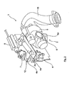
- the exhaust gas turbine or its housing 5 is in a first embodiment via an inflow 5a ( Fig. 4 ) directly to a flange 3b connected to a common line section 3c of the one-piece exhaust manifold 3 is formed.
- the line section 3c ( Fig. 4 ) connects to the two exhaust ports 3 d of the exhaust manifold 3 which open into the connection flanges 3 a.
- connection piece 3e To the exhaust manifold 3 may further be formed a connection piece 3e, to which an unillustrated exhaust gas recirculation line is connected to the intake system of the internal combustion engine.
- a throttle valve 8 In the connecting piece 3e, a throttle valve 8 is mounted as an exhaust gas recirculation valve via a shaft 7, which by means of an actuator 9 (FIG. Fig. 1 and 2 ) is controllable and determines the exhaust gas recirculation amount depending on operating parameters of the internal combustion engine.
- Both the EGR or throttle valve 8 and the brake flap 10 can thus be adjusted or adjusted in each case in dependence on defined predetermined operating parameters of the internal combustion engine.
- an actuator 13 for boost pressure control of the internal combustion engine is further attached, which controls a provided within the exhaust gas turbocharger 2 bypass line with a bypass valve (known type, not shown).
- the bypass line (the Fig. 4 shows in dashed lines 14 whose central axis) connects in a known manner the outgoing from the compressor 6 charge pressure line 6a ( Fig. 2 ) with the turbine inflow passage 5b ( Fig. 4 ) of the exhaust gas turbine 5, so that in the case of the rule in the Fig. 4 only shown schematically or indicated bypass flap 14a of the boost pressure of the internal combustion engine can be reduced.
- the centrally outgoing exhaust pipe 15 is connected, which is connectable to the further exhaust system of the internal combustion engine.
- the actuators 9, 12, 13 may be actuated, for example, electrically, hydraulically, pneumatically or electro-hydraulically and act on not further mentioned linkage or lever or the like on the shafts 7, 11 of the throttle valve 8 and the brake flap 10 and the bypass valve 14 a of boost pressure control.
- the actuators 9, 12, 13 are as in particular from the Fig. 1 and 2 can be seen at the top of the functional module 1 or above the exhaust manifold 3 in its installed position on the internal combustion engine arranged in a substantially uniform horizontal plane, wherein the actuators 9, 12 are fixed to the support bracket 4, while the actuator 13 for the wastegate on the Housing of the compressor 6 is attached.
- the fasteners are formed for example by screw not shown.
- the connecting piece 3e opposite line section 3f integrally formed on the other cylinder of the internal combustion engine or the exhaust gas into the functional module 1 are introduced. It is understood that the exhaust gas turbocharger 2 or its exhaust gas turbine 5 must be designed for the respective exhaust gas mass flows.
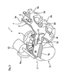
- the Fig. 3 shows an alternative embodiment of the exhaust manifold 3 and the exhaust gas turbine 5, in which the two components are integrally molded together or executed pouring two parts together poured.
- the mounting flanges 5a and 3b can be omitted thereby.
- the Fig. 3 shows here only the lower half of the exhaust gas turbine 5 and the exhaust manifold 3, wherein in the case of a casting two-piece molded variant, the uniform, planar separation surface 16, for example, in the central axis of the line sections 3c, 3d, 3e, 3f of the exhaust manifold 3 runs, so that here no Undercuts exist during demolding.
- the upper part of the housing of the exhaust gas turbine 5 and the exhaust manifold 3 would then also executable without undercuts.
- the component can also, as already mentioned above, be formed in one piece by casting, so that the representation of Fig. 3 at 16 then only the cut surfaces shows.
- the functional module 1 can be produced as a self-sufficient, separate pre-assembly unit, wherein the control functions of the actuators 9, 12, 13 can already be diagnosed and adjusted in advance on a corresponding test stand.
- the functional module 1 can be attached to the internal combustion engine with little installation effort, and the actuators 9, 12, 13 can be connected to an electronic engine control unit and, if appropriate, to hydraulic control devices (not shown) so as to be easily accessible from above.
- the exhaust manifold 3 may also be designed without an exhaust gas recirculation valve 8.
- the exhaust gas turbocharger 2 of the functional module 1 can be a high-pressure supercharger when the internal combustion engine is boosted, to which a low-pressure supercharger can be connected downstream of the exhaust gas turbine.
- the exhaust manifold 3 may basically be formed in one piece or be formed in several parts, in which case the individual manifold parts are connected to each other in the latter case.
Landscapes
- Engineering & Computer Science (AREA)
- Chemical & Material Sciences (AREA)
- Combustion & Propulsion (AREA)
- Mechanical Engineering (AREA)
- General Engineering & Computer Science (AREA)
- Supercharger (AREA)
- Exhaust Silencers (AREA)
- Control Of Throttle Valves Provided In The Intake System Or In The Exhaust System (AREA)
- Exhaust-Gas Circulating Devices (AREA)
Abstract
Description
- Die vorliegende Erfindung betrifft ein Funktionsmodul mit einem Abgasturbolader und einem Abgaskrümmer für eine turboaufgeladene Brennkraftmaschine in Kraftfahrzeugen gemäß dem Oberbegriff des Patentanspruchs 1.
- Bei turboaufgeladenen Brennkraftmaschinen in Kraftfahrzeugen ist es allgemein bekannt, den Abgasturbolader bzw. dessen Abgasturbine sofern baulich möglich unmittelbar an den Abgaskrümmer der Brennkraftmaschine anzubauen, um Wirkungsgradverluste zu vermeiden und im instationären Betrieb ein schnelles Ansprechen des Turboladers sicherzustellen. Auch Einrichtungen zur Ladedruckregelung mittels eines Bypassventils und ggf. zur Abgasrückführung in das Ansaugsystem der Brennkraftmaschine sind üblich, um insbesondere Vorgaben zur Abgasreinigung zu erfüllen. Bei Nutzkraftfahrzeugen werden zudem auch Bremsklappen im Abgassystem zur Erzielung einer verstärkten Motorbremswirkung im Schubbetrieb des Kraftfahrzeugs eingesetzt.
- Aufgabe der Erfindung ist es, ein Funktionsmodul der gattungsgemäßen Art vorzuschlagen, das fertigungstechnisch günstig und baulich einfach ausgeführt ist.
- Diese Aufgabe wird erfindungsgemäß mit den Merkmalen des Patentanspruchs 1 gelöst. Vorteilhafte Ausgestaltungen und Weiterbildungen der Erfindung sind Gegenstand der Unteransprüche.
- Erfindungsgemäß wird vorgeschlagen, dass die Bremsklappe der Motorbremseinrichtung, die Bypassklappe der Ladedruckregelung und ggf. das Abgas-Rückführventil der Abgasrückführeinrichtung in ein Funktionsmodul integriert sind. Das erfindungsgemäße Funktionsmodul stellt eine gut handhabbare, kompakte und funktionsintegrierte Montageeinheit dar, die lediglich mit den entsprechenden, elektronischen Steuergeräten zu verbinden ist und die schon vorab relevante Systemdiagnosen ermöglicht bzw. einjustierbar ist. Der Anbau an die Brennkraftmaschine ist dann schnell und problemlos durchführbar.
- Dabei ist es besonders vorteilhaft, wenn an das Funktionsmodul die Betätigungseinrichtungen bzw. Aktuatoren (elektrisch und/oder pneumatisch und/oder hydraulisch) der Bremsklappe und/oder der Bypassklappe und ggf. des Rückführventils bereits angebaut sind.
- Zur Erzielung einer robusten und unter anderem auch schwingungsresistenten Konstruktion des Funktionsmoduls kann an dem Abgasturbolader eine Stützkonsole vorgesehen sein, die in vorteilhafter Weise zugleich ein Wärmeschutzschild am Abgaskrümmer bildet. Das Wärmeschutzschild vermeidet insbesondere zu hohe Wärmeabstrahlungen und Umgebungstemperaturen im Motorraum des Kraftfahrzeugs und kann wenigstens bereichsweise durch einen isolierenden Luftspalt vom Abgaskrümmer getrennt bzw. beabstandet sein.
- Des Weiteren können die Aktuatoren für die Abgasrückführung und die Bremsklappe in Einbaulage des Funktionsmoduls gut zugänglich an dessen Oberseite positioniert und an der Stützkonsole befestigt sein, wodurch Prüf- oder Einstellarbeiten erleichtert werden. Gleiches trifft für den Aktuator für die Ladedrucksteuerung zu, der bevorzugt am Verdichtergehäuse an dessen Oberseite befestigt ist. Im Wesentlichen können dabei sämtliche Aktuatoren in einer einheitlichen Horizontalebene oberhalb der Anschlussflansche des Abgaskrümmers und der Stützkonsole angeordnet sein.
- Das Abgas-Rückführventil kann in einer bevorzugten Ausführung durch eine einfache, in beliebige Zwischenstellungen steuerbare Drosselklappe gebildet sein, die in einem an den Abgaskrümmer angeformten Anschlussstutzen für eine Abgas-Rückführleitung angeordnet ist.
- Ferner kann in einer fertigungstechnisch günstigen und montagetechnisch einfachen, weiteren Ausgestaltung die Bremsklappe der Motorbremseinrichtung nahe der Abgasturbine des Abgasturboladers in einen Leitungsabschnitt des Abgaskrümmers eingesetzt sein. Die Bremsklappe könnte aber auch direkt innerhalb des Gehäuses der Abgasturbine positioniert werden, was dort jedoch gegebenenfalls gesonderte, konstruktive Umgestaltungen erfordern würde.
- Die Bypassklappe für die Ladedruckregelung kann grundsätzlich in den Abgasturbolader in einer die abgehende Ladedruckleitung des Verdichters mit der Abgasturbine verbindenden Bypassleitung angeordnet sein.
- In einer gießtechnisch vorteilhaften Weiterbildung der Erfindung können das Gehäuse der Abgasturbine und der Abgaskrümmer jeweils einteilig als Gußteil ausgeführt und über einander zugeordnete Anschlussbereiche, insbesondere Anschlussflansche miteinander verbunden bzw. aneinander befestigt sein, z.B. durch wenigstens eine Schraubverbindung.
- Alternativ können das Gehäuse der Abgasturbine und der Abgaskrümmer auch durch ein einteilig, insbesondere materialeinheitlich und/oder einstückig, hergestelltes Bauteil, insbesondere ein Gussbauteil, gebildet sein, insbesondere als ein Gesamtteil in einem Guss hergestellt sein.
- Weiter alternativ dazu können das Gehäuse der Abgasturbine und der Abgaskrümmer auch derart zweiteilig zusammengegossen ausgeführt und aneinander befestigt sein, dass die Trennfläche der beiden Teile in etwa entlang der Mittelachse der im Abgaskrümmer integrierten Leitungen liegt. Der Abgaskrümmer wäre dann zweischalig mit einer in das Gehäuse der Abgasturbine reichenden, ebenen Trennfläche hergestellt. Die beiden Teile können dann zum Beispiel miteinander verschraubt werden oder ggf. auch miteinander verschweißt sein.
- Der Abgaskrümmer kann ferner einteilig bzw. einstückig ausgebildet sein, z.B. als ein einteiliges Gussteil ausgebildet und hergestellt sein. Alternativ dazu kann der Abgaskrümmer aber auch mehrteilig ausgebildet sein, wobei die einzelnen Krümmerteile dann im fertig montierten Zustand fest miteinander verbunden sind und wenigstens eines der Krümmerteile Bestandteil des erfindungsgemäßen Funktionsmoduls bildet.
- An dem Abgaskrümmer kann stromauf dem Leitungsabschnitt zur Abgasturbine ein weiterer Leitungsabschnitt vorgesehen, z.B. angegossen sein, über den die Abgase weiterer Zylinder der Brennkraftmaschine einleitbar sind. Das Funktionsmodul kann somit für Brennkraftmaschinen unterschiedlicher Zylinderzahl eingesetzt sein, wobei der Leitungsabschnitt die notwendige Kombabilität herstellt.
- Schließlich kann der Abgasturbolader ein Hochdruck-Turbolader einer Registeraufladung der Brennkraftmaschine mit einem Hochdrucklader und einem abgasseitig stromab liegendem Niederdrucklader sein.
- Zwei Ausführungsbeispiele der Erfindung sind im Folgenden anhand der beigefügten, schematischen Zeichnung näher erläutert. Es zeigen:
- Fig. 1
- in raumbildlicher Darstellung ein Funktionsmodul für eine Brennkraftmaschine für Nutzfahrzeuge, mit einem Abgasturbolader, einem Abgaskrümmer und einer Stützkonsole in einer Ansicht auf den Anschlussflansch des Abgaskrümmers;
- Fig. 2
- das Funktionsmodul nach
Fig. 1 , in einer Ansicht von schräg oben auf den Abgasturbolader und die Aktuatoren zur Ladedruckregelung, zur Steuerung der Bremsklappe und des Abgasrückführventils; - Fig. 3
- einen Ansicht in einer Trennebene gemäß Linie III - III der
Fig. 1 durch den zweiteiligen Abgaskrümmer und das Gehäuse der Abgasturbine mit Darstellung der Bremsklappe und der Drosselklappe des Abgas-Rückführventils; - Fig. 4
- einen Querschnitt entlang Linie IV - IV der
Fig. 1 durch das Gehäuse der Abgasturbine und des Abgaskrümmers; und - Fig. 5
- in Einzeldarstellung einen alternativen, einteiligen Abgaskrümmer des Funktionsmoduls mit Teilschnitten im Bereich der Bremsklappe und der Drosselklappe des Abgas-Rückführventils.
- Die
Fig. 1 und2 zeigen in raumbildlicher Darstellung ein Funktionsmodul 1 für eine turboaufgeladene Reihen-Brennkraftmaschine mit einem ein Gussgehäuse aufweisenden Abgasturbolader 2 (soweit nicht anders beschrieben bekannter Bauart) und einem Abgaskrümmer 3 (bzw. einem Teilbereich eines mehrteiligen Abgaskrümmers), dessen Anschlussflansche 3a abgasseitig an einen Zylinderkopf für hier beispielhaft zwei Zylinder der Brennkraftmaschine (nicht dargestellt) angeschlossen sind. - Das Funktionsmodul 1 ist über eine nur äußerst schematisch dargestellte bzw. angedeutete Stützkonsole 4 an der Brennkraftmaschine abgestützt, wobei die Stützkonsole 4 zum Beispiel über nicht dargestellte Schraubverbindungen am Abgasturbolader 2 und/oder am Zylinderblock der Brennkraftmaschine befestigt ist.
- Die Stützkonsole 4 bildet mit einem den Abgaskrümmer 3, vorzugsweise unter Belassung eines definierten Luftspalts, umschließenden Abschnitt 4a zugleich ein Wärmeschutzschild aus.
- Der Abgasturbolader 2 setzt sich aus einer Abgasturbine 5 und einem Verdichter 6 zusammen, von denen nur die bevorzugt gusstechnisch hergestellten Gehäuse, nicht aber die Laufräder, deren Welle und Lagerungen dargestellt sind.
- Die Abgasturbine bzw. deren Gehäuse 5 ist in einem ersten Ausführungsbeispiel über einen Einströmflansch 5a (
Fig. 4 ) unmittelbar an einen Flansch 3b angeschlossen, der an einem gemeinsamen Leitungsabschnitt 3c des einteiligen Abgaskrümmers 3 ausgebildet ist. Der Leitungsabschnitt 3c (Fig. 4 ) schließt an die zwei in die Anschlussflansche 3a mündenden Abgaskanäle 3d des Abgaskrümmers 3 an. - An den Abgaskrümmer 3 kann ferner ein Anschlussstutzen 3e angeformt sein, an den eine nicht dargestellte Abgas-Rückführleitung zum Ansaugsystem der Brennkraftmaschine angeschlossen ist. In dem Anschlussstutzen 3e ist über eine Welle 7 eine Drosselklappe 8 als Abgas-Rückführventil gelagert, die mittels eines Aktuators 9 (
Fig. 1 und2 ) steuerbar ist und abhängig von Betriebsparametern der Brennkraftmaschine die Abgasrückführmenge bestimmt. - Des Weiteren ist in dem Leitungsabschnitt 3c des Abgaskrümmers 3 nahe dem Flansch 3b (
Fig. 4 ) eine Bremsklappe 10 auf einer Welle 11 gelagert, die in Abhängigkeit von vorgegebenen Betriebsparametern, z.B. für einen aktiven Bremsleistungseingriff, für eine Kühlung der Injektordüse etc., mittels eines weiteren Aktuators 12 in eine offene oder mehr oder minder geschlossene Stellung zur Einsteuerung einer Motorbremswirkung verstellbar ist. - Sowohl die AGR- bzw. Drosselklappe 8 als auch die Bremsklappe 10 können somit in Abhängigkeit von definiert vorgegebenen Betriebsparametern der Brennkraftmaschine jeweils stufenlos verstellt bzw. eingestellt werden.
- An dem Gehäuse 6 des Verdichters ist ferner ein Aktuator 13 zur Ladedruckregelung der Brennkraftmaschine befestigt, der eine innerhalb des Abgasturboladers 2 vorgesehene Bypassleitung mit einer Bypassklappe (bekannter Bauart, nicht dargestellt) steuert. Die Bypassleitung (die
Fig. 4 zeigt in gestrichelten Linien 14 deren Mittelachse) verbindet in bekannter Weise die vom Verdichter 6 abgehende Ladedruckleitung 6a (Fig. 2 ) mit dem Turbineneinströmkanal 5b (Fig. 4 ) der Abgasturbine 5, so dass im Abregelfall über die in derFig. 4 lediglich schematisch dargestellte bzw. angedeutete Bypassklappe 14a der Ladedruck der Brennkraftmaschine verringerbar ist. An die Abgasturbine 5 ist zudem die zentral abgehende Abgasleitung 15 angeschlossen, die mit dem weiteren Abgassystem der Brennkraftmaschine verbindbar ist. - Die Aktuatoren 9, 12, 13 können zum Beispiel elektrisch, hydraulisch, pneumatisch oder elektrohydraulisch betätigt sein und wirken über nicht weiter angeführte Gestänge bzw. Hebel oder dergleichen auf die Wellen 7, 11 der Drosselklappe 8 und der Bremsklappe 10 sowie auf die Bypassklappe 14a der Ladedruckregelung.
- Die Aktuatoren 9, 12, 13 sind wie insbesondere aus den
Fig. 1 und2 ersichtlich ist an der Oberseite des Funktionsmoduls 1 bzw. oberhalb des Abgaskrümmers 3 in dessen Einbaulage an der Brennkraftmaschine in einer im Wesentlichen einheitlichen Horizontalebene angeordnet, wobei die Aktuatoren 9, 12 an der Stützkonsole 4 befestigt sind, während der Aktuator 13 für die Ladedruckregelung an dem Gehäuse des Verdichters 6 befestigt ist. Die Befestigungen sind zum Beispiel durch nicht näher dargestellte Schraubverbindungen gebildet. - An dem Abgaskrümmer 3 (
Fig. 5 ) ist ein weiterer, dem Anschlussstutzen 3e gegenüber liegender Leitungsabschnitt 3f angeformt, über den weitere Zylinder der Brennkraftmaschine bzw. deren Abgas in das Funktionsmodul 1 einleitbar sind. Es versteht sich, dass der Abgasturbolader 2 bzw. dessen Abgasturbine 5 auf die jeweiligen Abgasmassenströme ausgelegt sein müssen. - Die
Fig. 3 zeigt eine alternative Ausgestaltung von Abgaskrümmer 3 und Abgasturbine 5, bei der die beiden Bauteile einstückig zusammengegossen oder gießtechnisch zweigeteilt zusammengegossen ausgeführt sind. Die Befestigungsflansche 5a und 3b können dadurch entfallen. - Die
Fig. 3 zeigt hier lediglich die untere Hälfte der Abgasturbine 5 und des Abgaskrümmers 3, wobei im Falle einer gießtechnisch zweiteilig zusammengegossenen Variante die einheitliche, plane Trennfläche 16 z.B. in der Mittelachse der Leitungsabschnitte 3c, 3d, 3e, 3f des Abgaskrümmers 3 verläuft, so dass hier keine Hinterschnitte bei der Entformung vorliegen. Der obere Teil des Gehäuses der Abgasturbine 5 und des Abgaskrümmers 3 (nicht dargestellt) wäre dann ebenfalls ohne Hinterschnitte ausführbar. Das Bauteil kann aber auch, wie oben bereits erwähnt, insgesamt einstückig durch Gießen ausgebildet sein, so dass die Darstellung derFig. 3 bei 16 dann lediglich die Schnittflächen zeigt. - Das Funktionsmodul 1 kann als autarke, separate Vormontageeinheit hergestellt werden, wobei die Steuerungsfunktionen der Aktuatoren 9, 12, 13 auf einem entsprechenden Prüfstand bereits vorab diagnostiziert und einjustiert werden können.
- Sodann kann das Funktionsmodul 1 mit geringem Montageaufwand an der Brennkraftmaschine befestigt und die Aktuatoren 9, 12, 13 an ein elektronisches Motorsteuergerät und gegebenenfalls an hydraulische Steuereinrichtungen (nicht dargestellt) von oben gut zugänglich angeschlossen werden.
- Abweichend von den Ausführungsbeispielen kann der Abgaskrümmer 3 ggf. auch ohne Abgasrückführventil 8 konzipiert sein. Der Abgasturbolader 2 des Funktionsmoduls 1 kann bei einer Registeraufladung der Brennkraftmaschine ein Hochdrucklader sein, an den stromab der Abgasturbine ein Niederdrucklader angeschlossen sein kann.
- Wie ebenfalls bereits erwähnt, kann der Abgaskrümmer 3 grundsätzlich einstückig ausgebildet sein oder mehrteilig ausgebildet sein, wobei dann im letzteren Falle die einzelnen Krümmerteile entsprechend miteinander verbunden sind.
-
- 1
- Funktionsmodul
- 2
- Abgasturbolader
- 3
- Abgaskrümmer
- 3a
- Anschlussflansche
- 3b
- Flansch
- 3c
- Leitungsabschnitt
- 3d
- Abgaskanäle
- 3e
- Anschlussstutzen
- 3f
- Leitungsabschnitt
- 4
- Stützkonsole
- 4a
- Abschnitt
- 5
- Abgasturbine
- 5a
- Einströmflansch
- 5b
- Einströmkanal
- 6
- Verdichter
- 6a
- Ladedruckleitung
- 7
- Welle
- 8
- Drosselklappe
- 9
- Aktuator
- 10
- Bremsklappe
- 11
- Welle
- 12
- Aktuator
- 13
- Aktuator
- 14
- Bypassleitung
- 14a
- Bypassklappe
- 15
- Abgasleitung
- 16
- Trennfläche oder Schnittebene
Claims (16)
- Funktionsmodul mit wenigstens einem Abgasturbolader und einem Abgaskrümmer für eine turboaufgeladene Brennkraftmaschine in Kraftfahrzeugen, wobei die Brennkraftmaschine eine Ladedrucksteuereinrichtung mit einer Bypassklappe, eine im Abgassystem angeordnete Bremsklappe zur Steuerung einer Motorbremswirkung aufweist, dadurch gekennzeichnet, dass die Bremsklappe (10) und die Bypassklappe (14a) in das Funktionsmodul (1) integriert sind.
- Funktionsmodul nach Anspruch 1, dadurch gekennzeichnet, dass die Brennkraftmaschine ferner eine Abgasrückführeinrichtung mit einem Rückführventil (8) aufweist, das ebenfalls in das Funktionsmodul (1) integriert ist.
- Funktionsmodul nach Anspruch 1 oder 2, dadurch gekennzeichnet, dass ferner eine Betätigungseinrichtung, insbesondere ein Aktuator (9, 12, 13), zur Betätigung der Bremsklappe (10) und/oder der Bypassklappe (14a) und/oder eines Rückführventils (8) einer Abgasrückführeinrichtung Bestandteil des Funktionsmoduls (1) ist, insbesondere die jeweiligen Aktuatoren (9, 12, 13) an das Funktionsmodul (1) angebaut sind.
- Funktionsmodul nach einem der vorhergehenden Ansprüche, dadurch gekennzeichnet, dass an dem Abgasturbolader (2) eine Stützkonsole (4) vorgesehen ist, die zugleich ein Wärmeschutzschild (4a) für den Abgaskrümmer (3) bildet.
- Funktionsmodul nach Anspruch 4, dadurch gekennzeichnet, dass die Stützkonsole (4) vom Abgaskrümmer (3) durch einen isolierenden Luftspalt getrennt und/oder beabstandet ist.
- Funktionsmodul nach einem der vorhergehenden Ansprüche, dadurch gekennzeichnet, dass eine Betätigungseinrichtung, insbesondere ein Akuator (9, 12), für eine Abgasrückführung und/oder die Bremsklappe (10) in Einbaulage des Funktionsmoduls (1) an dessen Oberseite positioniert und an der Stützkonsole (4) befestigt ist.
- Funktionsmodul nach einem der vorhergehenden Ansprüche, dadurch gekennzeichnet, dass eine Betätigungseinrichtung, insbesondere ein Aktuator (13), für die Ladedrucksteuerung am Verdichtergehäuse (6), bezogen auf die Einbaulage, an dessen Oberseite befestigt ist.
- Funktionsmodul nach Anspruch 6 oder 7, dadurch gekennzeichnet, dass sämtliche Betätigungseinrichtungen, insbesondere Aktuatoren (9, 12, 13), im Wesentlichen in einer einheitlichen Horizontalebene oberhalb der Anschlussflansche (3a) des Abgaskrümmers (3) und der Stützkonsole (4) angeordnet sind.
- Funktionsmodul nach einem der vorhergehenden Ansprüche, dadurch gekennzeichnet, dass das Abgas-Rückführventil durch eine Drosselklappe (8) gebildet ist, die in einem an den Abgaskrümmer (3) angeformten Anschlussstutzen (3e) angeordnet ist.
- Funktionsmodul nach einem der vorhergehenden Ansprüche, dadurch gekennzeichnet, dass die Bremsklappe (10) nahe der Abgasturbine (5) des Abgasturboladers (2) in einen Leitungsabschnitt (3c) des Abgaskrümmers (3) eingesetzt ist.
- Funktionsmodul nach einem der vorhergehenden Ansprüche, dadurch gekennzeichnet, dass die Bypassklappe (14a) in den Abgasturbolader (2) in einer die abgehende Ladedruckleitung (6a) des Verdichters (6) mit der Abgasturbine (5) verbindenden Bypassleitung (14) angeordnet ist.
- Funktionsmodul nach einem der vorhergehenden Ansprüche, dadurch gekennzeichnet, dass das Gehäuse der Abgasturbine (5) und der Abgaskrümmer (3) jeweils durch separate Bauteile, insbesondere durch separate sowie durch Gießen hergestellte Bauteile, gebildet sind, die vorzugsweise über Anschlussflansche (5a, 3b) als Anschlussbereiche miteinander verbunden sind, oder dass das Gehäuse der Abgasturbine (5) und der Abgaskrümmer (3) durch ein einteilig, insbesondere materialeinheitlich und/oder einstückig, hergestelltes Bauteil, insbesondere ein Gussbauteil, gebildet ist oder dass das Gehäuse der Abgasturbine (5) und der Abgaskrümmer (3) dergestalt zweiteilig zusammengegossen ausgeführt sind, dass der Abgaskrümmer (3) eine in das Gehäuse der Abgasturbine (5) reichende, ebene Trennfläche aufweist, insbesondere die Trennfläche der beiden Teile in etwa entlang der Mittelachse der im Abgaskrümmer (3) integrierten Leitungen (3c, 3d, 3e, 3f) verläuft, wobei die beiden Teile miteinander fest verbunden sind, insbesondere mittels wenigstens einer Schraubverbindung fest verbunden sind.
- Funktionsmodul nach einem der vorhergehenden Ansprüche, dadurch gekennzeichnet, dass der Abgaskrümmer (3) einteilig oder mehrteilig ausgebildet ist, wobei im Falle eines mehrteilig ausgebildeten Abgaskrümmers (3) die einzelnen Krümmerteile miteinander verbunden sind und wenigstens eines der Krümmerteile Bestandteil des Funktionsmoduls bildet.
- Funktionsmodul nach einem der vorhergehenden Ansprüche, dadurch gekennzeichnet, dass an dem Abgaskrümmer (3) stromauf eines zur Abgasturbine (5) führenden Leitungsabschnitts (3c) ein weiterer Leitungsabschnitt (3f) vorgesehen, insbesondere angegossen ist, über den die Abgase wenigstens eines weiteren Zylinders der Brennkraftmaschine einleitbar sind.
- Funktionsmodul nach einem der vorhergehenden Ansprüche, dadurch gekennzeichnet, dass der Abgasturbolader (2) ein Hochdruck-Turbolader einer Registeraufladung der Brennkraftmaschine mit einem Hochdrucklader und einem abgasseitig stromab liegendem Niederdrucklader ist.
- Kraftfahrzeug, insbesondere Nutzfahrzeug, mit einem Funktionsmodul nach einem oder mehreren der vorhergehenden Ansprüche.
Applications Claiming Priority (1)
| Application Number | Priority Date | Filing Date | Title |
|---|---|---|---|
| ATA269/2012A AT512567B1 (de) | 2012-03-01 | 2012-03-01 | Funktionsmodul mit einem Abgasturbolader und einem Abgaskrümmer |
Publications (3)
| Publication Number | Publication Date |
|---|---|
| EP2634393A2 true EP2634393A2 (de) | 2013-09-04 |
| EP2634393A3 EP2634393A3 (de) | 2015-04-22 |
| EP2634393B1 EP2634393B1 (de) | 2017-10-04 |
Family
ID=47018010
Family Applications (1)
| Application Number | Title | Priority Date | Filing Date |
|---|---|---|---|
| EP12007015.6A Active EP2634393B1 (de) | 2012-03-01 | 2012-10-10 | Funktionsmodul mit einem Abgasturbolader und einem Abgaskrümmer |
Country Status (5)
| Country | Link |
|---|---|
| EP (1) | EP2634393B1 (de) |
| CN (1) | CN103382883B (de) |
| AT (1) | AT512567B1 (de) |
| BR (1) | BR102013005124B1 (de) |
| RU (1) | RU2626030C2 (de) |
Cited By (4)
| Publication number | Priority date | Publication date | Assignee | Title |
|---|---|---|---|---|
| CN105351116A (zh) * | 2015-11-30 | 2016-02-24 | 康跃科技股份有限公司 | 一种循环进气系统 |
| EP3034844A1 (de) * | 2014-12-15 | 2016-06-22 | MAN Truck & Bus Österreich AG | Motorbremsvorrichtung für eine brennkraftmaschine sowie verfahren zum betreiben einer motorbremsvorrichtung |
| EP3048285A1 (de) * | 2015-01-20 | 2016-07-27 | KNORR-BREMSE Systeme für Nutzfahrzeuge GmbH | Bremsklappe und Abgassystem |
| WO2021139886A1 (de) * | 2020-01-09 | 2021-07-15 | Pierburg Gmbh | Abgassystem einer verbrennungskraftmaschine |
Families Citing this family (5)
| Publication number | Priority date | Publication date | Assignee | Title |
|---|---|---|---|---|
| CN103835841B (zh) * | 2014-02-25 | 2016-12-07 | 长城汽车股份有限公司 | Egr阀控制装置及具有其的车辆 |
| DE102014005212A1 (de) | 2014-04-09 | 2015-10-15 | Man Truck & Bus Ag | Abgaskrümmer für eine Brennkraftmaschine, insbesondere in Kraftfahrzeugen |
| DE102015121617B4 (de) * | 2015-12-11 | 2021-01-28 | Ford-Werke Gmbh | Regelvorrichtung für eine Verbrennungskraftmaschine |
| DE102016213386A1 (de) * | 2016-07-21 | 2018-01-25 | Ford Global Technologies, Llc | Brennkraftmaschine mit Abgasturboaufladung und Verfahren zum Betreiben einer derartigen Brennkraftmaschine |
| CN106286025B (zh) * | 2016-11-10 | 2018-07-31 | 无锡隆盛科技股份有限公司 | 防冲开真空egr阀 |
Citations (5)
| Publication number | Priority date | Publication date | Assignee | Title |
|---|---|---|---|---|
| DE10222919A1 (de) * | 2002-05-24 | 2003-12-24 | Man Nutzfahrzeuge Ag | Zweistufig aufgeladene Brennkraftmaschine |
| WO2007147513A1 (de) * | 2006-06-21 | 2007-12-27 | Daimler Ag | Abgaskrümmer |
| WO2008076013A1 (en) * | 2006-12-20 | 2008-06-26 | Volvo Lastvagnar Ab | Engine brake for vehicle |
| EP2050940A1 (de) * | 2006-08-10 | 2009-04-22 | Mitsubishi Heavy Industries, Ltd. | Verfahren zur herstellung eines mehrstufigen abgasturbolader |
| EP2206899A1 (de) * | 2009-01-13 | 2010-07-14 | MAN Nutzfahrzeuge Aktiengesellschaft | Verfahren zur Nachbehandlung eines Abgasstroms einer mehrzylindrigen Brennkkraftmaschine eines Fahrzeuges sowie Abgasnachbehandlungsvorrichtung |
Family Cites Families (4)
| Publication number | Priority date | Publication date | Assignee | Title |
|---|---|---|---|---|
| DE19630224A1 (de) * | 1996-07-26 | 1998-01-29 | Daimler Benz Ag | Motorbremsvorrichtung |
| EP1762716B1 (de) * | 2005-09-07 | 2012-11-21 | BorgWarner, Inc. | Bremsklappe mit Bypass |
| DE102009019437A1 (de) * | 2009-04-29 | 2010-11-04 | Man Nutzfahrzeuge Ag | Vorrichtung zur Steigerung der Bremsleistung einer mehrzylindrigen Brennkraftmaschine eines Fahrzeugs während des Motorbremsbetriebes |
| US20110173972A1 (en) * | 2010-06-14 | 2011-07-21 | Robert Andrew Wade | Internal Combustion Engine Cylinder Head With Integral Exhaust Ducting And Turbocharger Housing |
-
2012
- 2012-03-01 AT ATA269/2012A patent/AT512567B1/de active
- 2012-10-10 EP EP12007015.6A patent/EP2634393B1/de active Active
-
2013
- 2013-02-14 RU RU2013106517A patent/RU2626030C2/ru active
- 2013-03-01 CN CN201310064953.XA patent/CN103382883B/zh active Active
- 2013-03-01 BR BR102013005124-1A patent/BR102013005124B1/pt active IP Right Grant
Patent Citations (5)
| Publication number | Priority date | Publication date | Assignee | Title |
|---|---|---|---|---|
| DE10222919A1 (de) * | 2002-05-24 | 2003-12-24 | Man Nutzfahrzeuge Ag | Zweistufig aufgeladene Brennkraftmaschine |
| WO2007147513A1 (de) * | 2006-06-21 | 2007-12-27 | Daimler Ag | Abgaskrümmer |
| EP2050940A1 (de) * | 2006-08-10 | 2009-04-22 | Mitsubishi Heavy Industries, Ltd. | Verfahren zur herstellung eines mehrstufigen abgasturbolader |
| WO2008076013A1 (en) * | 2006-12-20 | 2008-06-26 | Volvo Lastvagnar Ab | Engine brake for vehicle |
| EP2206899A1 (de) * | 2009-01-13 | 2010-07-14 | MAN Nutzfahrzeuge Aktiengesellschaft | Verfahren zur Nachbehandlung eines Abgasstroms einer mehrzylindrigen Brennkkraftmaschine eines Fahrzeuges sowie Abgasnachbehandlungsvorrichtung |
Cited By (7)
| Publication number | Priority date | Publication date | Assignee | Title |
|---|---|---|---|---|
| EP3034844A1 (de) * | 2014-12-15 | 2016-06-22 | MAN Truck & Bus Österreich AG | Motorbremsvorrichtung für eine brennkraftmaschine sowie verfahren zum betreiben einer motorbremsvorrichtung |
| US10267238B2 (en) | 2014-12-15 | 2019-04-23 | MAN Truck & Bus Österreich AG | Engine braking device for a combustion engine and method for operating an engine braking device |
| EP3048285A1 (de) * | 2015-01-20 | 2016-07-27 | KNORR-BREMSE Systeme für Nutzfahrzeuge GmbH | Bremsklappe und Abgassystem |
| WO2016116229A1 (en) * | 2015-01-20 | 2016-07-28 | Knorr-Bremse Systeme für Nutzfahrzeuge GmbH | Braking flap and exhaust gas system |
| CN105351116A (zh) * | 2015-11-30 | 2016-02-24 | 康跃科技股份有限公司 | 一种循环进气系统 |
| CN105351116B (zh) * | 2015-11-30 | 2019-09-10 | 康跃科技股份有限公司 | 一种循环进气系统 |
| WO2021139886A1 (de) * | 2020-01-09 | 2021-07-15 | Pierburg Gmbh | Abgassystem einer verbrennungskraftmaschine |
Also Published As
| Publication number | Publication date |
|---|---|
| RU2626030C2 (ru) | 2017-07-21 |
| CN103382883B (zh) | 2017-11-24 |
| BR102013005124B1 (pt) | 2022-03-08 |
| EP2634393A3 (de) | 2015-04-22 |
| EP2634393B1 (de) | 2017-10-04 |
| RU2013106517A (ru) | 2014-08-20 |
| CN103382883A (zh) | 2013-11-06 |
| BR102013005124A2 (pt) | 2015-08-25 |
| AT512567B1 (de) | 2014-03-15 |
| AT512567A1 (de) | 2013-09-15 |
Similar Documents
| Publication | Publication Date | Title |
|---|---|---|
| EP2634393B1 (de) | Funktionsmodul mit einem Abgasturbolader und einem Abgaskrümmer | |
| EP1394380B1 (de) | Aufladesystem für eine Brennkraftmaschine | |
| EP3034843B1 (de) | Verfahren zum steuern einer motorbremsvorrichtung sowie motorbremsvorrichtung | |
| EP2419615B1 (de) | Ladeluftkanal für einen verbrennungsmotor | |
| DE102008052170A1 (de) | Zweistufige Abgasturboaufladung für eine Brennkraftmaschine | |
| EP2267285A2 (de) | Abgasbaugruppe | |
| DE102006011188A1 (de) | Zweistufige Abgasturboaufladung für eine Brennkraftmaschine | |
| DE102006054117A1 (de) | Im Teil- und Volllastbetrieb gesteuerte Kurbelgehäuse-Belüftung einer Brennkraftmaschine | |
| DE102008056337A1 (de) | Brennkraftmaschine mit Abgasrückführung | |
| WO2014124807A1 (de) | Brennkraftmaschine mit booster | |
| DE102011116310A1 (de) | Anordnung einer Luftversorgungseinrichtung an einem Zylinderkopf für eine Verbrennungskraftmaschine | |
| EP2256314A1 (de) | Verbrennungsmotor | |
| WO2009129894A1 (de) | Abgasstromführungseinrichtung und brennkraftmaschine mit einer abgasstromführungseinrichtung | |
| EP1619365B1 (de) | Abgasnachbehandlung mit sequentieller Aufladung | |
| DE102017207363A1 (de) | Verbrennungsmotor-zylinderkopf mit integriertem abgaskrümmer mit mehreren kanälen und mehreren anschlüssen | |
| DE102010045503A1 (de) | Vorrichtung zur Abgasrückführung an einer Brennkraftmaschine | |
| EP2737195B1 (de) | Aufgeladene brennkraftmaschine | |
| DE102011107120A1 (de) | Aufladeeinrichtung für eine Verbrennungskraftmaschine | |
| DE102015203157A1 (de) | Isolierende Metallstruktur in einem Abgastrakt mit zwei Turboladern | |
| DE202015101104U1 (de) | Isolierende Metallstruktur in einem Abgastrakt mit zwei Turboladern | |
| DE102009051261B4 (de) | Verfahren zum Betreiben einer Motorbremse eines Kraftwagens | |
| DE102018006413A1 (de) | Verbrennungskraftmaschine für einen Kraftwagen mit einem Abgaskrümmer und mit einem Abgasrückführventil | |
| EP2014893B1 (de) | Umluftsystem für einen Abgasturbolader | |
| EP2432979B1 (de) | Gehäuse einer frischgasversorgungseinrichtung für eine verbrennungsmaschine und frischgasversorgungseinrichtung | |
| DE102011088019A1 (de) | Verbrennungskraftmaschine mit Abgasturbolader und Abgaskühler sowie Verfahren zur Steuerung/Regelung der Betriebstemperatur des Abgasturboladers |
Legal Events
| Date | Code | Title | Description |
|---|---|---|---|
| PUAI | Public reference made under article 153(3) epc to a published international application that has entered the european phase |
Free format text: ORIGINAL CODE: 0009012 |
|
| AK | Designated contracting states |
Kind code of ref document: A2 Designated state(s): AL AT BE BG CH CY CZ DE DK EE ES FI FR GB GR HR HU IE IS IT LI LT LU LV MC MK MT NL NO PL PT RO RS SE SI SK SM TR |
|
| AX | Request for extension of the european patent |
Extension state: BA ME |
|
| RIN1 | Information on inventor provided before grant (corrected) |
Inventor name: RAAB, GOTTFRIED Inventor name: AIGINGER, FRANZ Inventor name: STEPANEK, PAVEL Inventor name: SCHATZBERGER, THOROLF |
|
| PUAL | Search report despatched |
Free format text: ORIGINAL CODE: 0009013 |
|
| AK | Designated contracting states |
Kind code of ref document: A3 Designated state(s): AL AT BE BG CH CY CZ DE DK EE ES FI FR GB GR HR HU IE IS IT LI LT LU LV MC MK MT NL NO PL PT RO RS SE SI SK SM TR |
|
| AX | Request for extension of the european patent |
Extension state: BA ME |
|
| RIC1 | Information provided on ipc code assigned before grant |
Ipc: F01N 13/10 20100101ALI20150317BHEP Ipc: F02B 37/22 20060101ALI20150317BHEP Ipc: F02M 25/07 20060101ALI20150317BHEP Ipc: F02D 9/06 20060101ALI20150317BHEP Ipc: F02B 37/18 20060101AFI20150317BHEP |
|
| 17P | Request for examination filed |
Effective date: 20150409 |
|
| 17Q | First examination report despatched |
Effective date: 20160608 |
|
| REG | Reference to a national code |
Ref country code: DE Ref legal event code: R079 Ref document number: 502012011362 Country of ref document: DE Free format text: PREVIOUS MAIN CLASS: F02B0037180000 Ipc: F02B0037160000 |
|
| RIC1 | Information provided on ipc code assigned before grant |
Ipc: F02M 26/06 20160101ALI20170316BHEP Ipc: F02B 37/18 20060101ALI20170316BHEP Ipc: F02M 26/70 20160101ALI20170316BHEP Ipc: F02M 26/10 20160101ALI20170316BHEP Ipc: F01N 13/10 20100101ALI20170316BHEP Ipc: F02D 9/06 20060101ALI20170316BHEP Ipc: F02B 37/16 20060101AFI20170316BHEP Ipc: F02M 26/16 20160101ALI20170316BHEP Ipc: F02B 37/22 20060101ALI20170316BHEP |
|
| GRAP | Despatch of communication of intention to grant a patent |
Free format text: ORIGINAL CODE: EPIDOSNIGR1 |
|
| INTG | Intention to grant announced |
Effective date: 20170425 |
|
| GRAS | Grant fee paid |
Free format text: ORIGINAL CODE: EPIDOSNIGR3 |
|
| GRAA | (expected) grant |
Free format text: ORIGINAL CODE: 0009210 |
|
| AK | Designated contracting states |
Kind code of ref document: B1 Designated state(s): AL AT BE BG CH CY CZ DE DK EE ES FI FR GB GR HR HU IE IS IT LI LT LU LV MC MK MT NL NO PL PT RO RS SE SI SK SM TR |
|
| REG | Reference to a national code |
Ref country code: GB Ref legal event code: FG4D Free format text: NOT ENGLISH |
|
| REG | Reference to a national code |
Ref country code: CH Ref legal event code: EP |
|
| REG | Reference to a national code |
Ref country code: AT Ref legal event code: REF Ref document number: 934278 Country of ref document: AT Kind code of ref document: T Effective date: 20171015 |
|
| REG | Reference to a national code |
Ref country code: FR Ref legal event code: PLFP Year of fee payment: 6 |
|
| REG | Reference to a national code |
Ref country code: IE Ref legal event code: FG4D Free format text: LANGUAGE OF EP DOCUMENT: GERMAN |
|
| REG | Reference to a national code |
Ref country code: DE Ref legal event code: R096 Ref document number: 502012011362 Country of ref document: DE |
|
| REG | Reference to a national code |
Ref country code: NL Ref legal event code: FP |
|
| REG | Reference to a national code |
Ref country code: SE Ref legal event code: TRGR |
|
| REG | Reference to a national code |
Ref country code: LT Ref legal event code: MG4D |
|
| PG25 | Lapsed in a contracting state [announced via postgrant information from national office to epo] |
Ref country code: LT Free format text: LAPSE BECAUSE OF FAILURE TO SUBMIT A TRANSLATION OF THE DESCRIPTION OR TO PAY THE FEE WITHIN THE PRESCRIBED TIME-LIMIT Effective date: 20171004 Ref country code: FI Free format text: LAPSE BECAUSE OF FAILURE TO SUBMIT A TRANSLATION OF THE DESCRIPTION OR TO PAY THE FEE WITHIN THE PRESCRIBED TIME-LIMIT Effective date: 20171004 Ref country code: ES Free format text: LAPSE BECAUSE OF FAILURE TO SUBMIT A TRANSLATION OF THE DESCRIPTION OR TO PAY THE FEE WITHIN THE PRESCRIBED TIME-LIMIT Effective date: 20171004 Ref country code: NO Free format text: LAPSE BECAUSE OF FAILURE TO SUBMIT A TRANSLATION OF THE DESCRIPTION OR TO PAY THE FEE WITHIN THE PRESCRIBED TIME-LIMIT Effective date: 20180104 |
|
| PG25 | Lapsed in a contracting state [announced via postgrant information from national office to epo] |
Ref country code: BG Free format text: LAPSE BECAUSE OF FAILURE TO SUBMIT A TRANSLATION OF THE DESCRIPTION OR TO PAY THE FEE WITHIN THE PRESCRIBED TIME-LIMIT Effective date: 20180104 Ref country code: LV Free format text: LAPSE BECAUSE OF FAILURE TO SUBMIT A TRANSLATION OF THE DESCRIPTION OR TO PAY THE FEE WITHIN THE PRESCRIBED TIME-LIMIT Effective date: 20171004 Ref country code: RS Free format text: LAPSE BECAUSE OF FAILURE TO SUBMIT A TRANSLATION OF THE DESCRIPTION OR TO PAY THE FEE WITHIN THE PRESCRIBED TIME-LIMIT Effective date: 20171004 Ref country code: IS Free format text: LAPSE BECAUSE OF FAILURE TO SUBMIT A TRANSLATION OF THE DESCRIPTION OR TO PAY THE FEE WITHIN THE PRESCRIBED TIME-LIMIT Effective date: 20180204 Ref country code: GR Free format text: LAPSE BECAUSE OF FAILURE TO SUBMIT A TRANSLATION OF THE DESCRIPTION OR TO PAY THE FEE WITHIN THE PRESCRIBED TIME-LIMIT Effective date: 20180105 Ref country code: HR Free format text: LAPSE BECAUSE OF FAILURE TO SUBMIT A TRANSLATION OF THE DESCRIPTION OR TO PAY THE FEE WITHIN THE PRESCRIBED TIME-LIMIT Effective date: 20171004 |
|
| REG | Reference to a national code |
Ref country code: CH Ref legal event code: PL |
|
| REG | Reference to a national code |
Ref country code: DE Ref legal event code: R097 Ref document number: 502012011362 Country of ref document: DE |
|
| REG | Reference to a national code |
Ref country code: IE Ref legal event code: MM4A |
|
| PG25 | Lapsed in a contracting state [announced via postgrant information from national office to epo] |
Ref country code: LI Free format text: LAPSE BECAUSE OF NON-PAYMENT OF DUE FEES Effective date: 20171031 Ref country code: SK Free format text: LAPSE BECAUSE OF FAILURE TO SUBMIT A TRANSLATION OF THE DESCRIPTION OR TO PAY THE FEE WITHIN THE PRESCRIBED TIME-LIMIT Effective date: 20171004 Ref country code: MC Free format text: LAPSE BECAUSE OF FAILURE TO SUBMIT A TRANSLATION OF THE DESCRIPTION OR TO PAY THE FEE WITHIN THE PRESCRIBED TIME-LIMIT Effective date: 20171004 Ref country code: DK Free format text: LAPSE BECAUSE OF FAILURE TO SUBMIT A TRANSLATION OF THE DESCRIPTION OR TO PAY THE FEE WITHIN THE PRESCRIBED TIME-LIMIT Effective date: 20171004 Ref country code: CH Free format text: LAPSE BECAUSE OF NON-PAYMENT OF DUE FEES Effective date: 20171031 Ref country code: CZ Free format text: LAPSE BECAUSE OF FAILURE TO SUBMIT A TRANSLATION OF THE DESCRIPTION OR TO PAY THE FEE WITHIN THE PRESCRIBED TIME-LIMIT Effective date: 20171004 Ref country code: LU Free format text: LAPSE BECAUSE OF NON-PAYMENT OF DUE FEES Effective date: 20171010 Ref country code: EE Free format text: LAPSE BECAUSE OF FAILURE TO SUBMIT A TRANSLATION OF THE DESCRIPTION OR TO PAY THE FEE WITHIN THE PRESCRIBED TIME-LIMIT Effective date: 20171004 |
|
| PLBE | No opposition filed within time limit |
Free format text: ORIGINAL CODE: 0009261 |
|
| STAA | Information on the status of an ep patent application or granted ep patent |
Free format text: STATUS: NO OPPOSITION FILED WITHIN TIME LIMIT |
|
| REG | Reference to a national code |
Ref country code: BE Ref legal event code: MM Effective date: 20171031 |
|
| PG25 | Lapsed in a contracting state [announced via postgrant information from national office to epo] |
Ref country code: SM Free format text: LAPSE BECAUSE OF FAILURE TO SUBMIT A TRANSLATION OF THE DESCRIPTION OR TO PAY THE FEE WITHIN THE PRESCRIBED TIME-LIMIT Effective date: 20171004 Ref country code: PL Free format text: LAPSE BECAUSE OF FAILURE TO SUBMIT A TRANSLATION OF THE DESCRIPTION OR TO PAY THE FEE WITHIN THE PRESCRIBED TIME-LIMIT Effective date: 20171004 Ref country code: BE Free format text: LAPSE BECAUSE OF NON-PAYMENT OF DUE FEES Effective date: 20171031 Ref country code: RO Free format text: LAPSE BECAUSE OF FAILURE TO SUBMIT A TRANSLATION OF THE DESCRIPTION OR TO PAY THE FEE WITHIN THE PRESCRIBED TIME-LIMIT Effective date: 20171004 |
|
| 26N | No opposition filed |
Effective date: 20180705 |
|
| GBPC | Gb: european patent ceased through non-payment of renewal fee |
Effective date: 20180104 |
|
| PG25 | Lapsed in a contracting state [announced via postgrant information from national office to epo] |
Ref country code: MT Free format text: LAPSE BECAUSE OF FAILURE TO SUBMIT A TRANSLATION OF THE DESCRIPTION OR TO PAY THE FEE WITHIN THE PRESCRIBED TIME-LIMIT Effective date: 20171004 |
|
| REG | Reference to a national code |
Ref country code: FR Ref legal event code: PLFP Year of fee payment: 7 |
|
| PG25 | Lapsed in a contracting state [announced via postgrant information from national office to epo] |
Ref country code: IE Free format text: LAPSE BECAUSE OF NON-PAYMENT OF DUE FEES Effective date: 20171010 |
|
| PG25 | Lapsed in a contracting state [announced via postgrant information from national office to epo] |
Ref country code: SI Free format text: LAPSE BECAUSE OF FAILURE TO SUBMIT A TRANSLATION OF THE DESCRIPTION OR TO PAY THE FEE WITHIN THE PRESCRIBED TIME-LIMIT Effective date: 20171004 Ref country code: GB Free format text: LAPSE BECAUSE OF NON-PAYMENT OF DUE FEES Effective date: 20180104 |
|
| REG | Reference to a national code |
Ref country code: AT Ref legal event code: MM01 Ref document number: 934278 Country of ref document: AT Kind code of ref document: T Effective date: 20171010 |
|
| PG25 | Lapsed in a contracting state [announced via postgrant information from national office to epo] |
Ref country code: AT Free format text: LAPSE BECAUSE OF NON-PAYMENT OF DUE FEES Effective date: 20171010 |
|
| PG25 | Lapsed in a contracting state [announced via postgrant information from national office to epo] |
Ref country code: HU Free format text: LAPSE BECAUSE OF FAILURE TO SUBMIT A TRANSLATION OF THE DESCRIPTION OR TO PAY THE FEE WITHIN THE PRESCRIBED TIME-LIMIT; INVALID AB INITIO Effective date: 20121010 |
|
| PG25 | Lapsed in a contracting state [announced via postgrant information from national office to epo] |
Ref country code: CY Free format text: LAPSE BECAUSE OF NON-PAYMENT OF DUE FEES Effective date: 20171004 |
|
| PG25 | Lapsed in a contracting state [announced via postgrant information from national office to epo] |
Ref country code: MK Free format text: LAPSE BECAUSE OF FAILURE TO SUBMIT A TRANSLATION OF THE DESCRIPTION OR TO PAY THE FEE WITHIN THE PRESCRIBED TIME-LIMIT Effective date: 20171004 |
|
| PG25 | Lapsed in a contracting state [announced via postgrant information from national office to epo] |
Ref country code: TR Free format text: LAPSE BECAUSE OF FAILURE TO SUBMIT A TRANSLATION OF THE DESCRIPTION OR TO PAY THE FEE WITHIN THE PRESCRIBED TIME-LIMIT Effective date: 20171004 |
|
| PG25 | Lapsed in a contracting state [announced via postgrant information from national office to epo] |
Ref country code: PT Free format text: LAPSE BECAUSE OF FAILURE TO SUBMIT A TRANSLATION OF THE DESCRIPTION OR TO PAY THE FEE WITHIN THE PRESCRIBED TIME-LIMIT Effective date: 20171004 |
|
| PG25 | Lapsed in a contracting state [announced via postgrant information from national office to epo] |
Ref country code: AL Free format text: LAPSE BECAUSE OF FAILURE TO SUBMIT A TRANSLATION OF THE DESCRIPTION OR TO PAY THE FEE WITHIN THE PRESCRIBED TIME-LIMIT Effective date: 20171004 |
|
| REG | Reference to a national code |
Ref country code: DE Ref legal event code: R081 Ref document number: 502012011362 Country of ref document: DE Owner name: MAN TRUCK & BUS SE, DE Free format text: FORMER OWNER: MAN TRUCK & BUS OESTERREICH AG, STEYR, AT |
|
| REG | Reference to a national code |
Ref country code: NL Ref legal event code: PD Owner name: MAN TRUCK & BUS OESTERREICH GESMBH; AT Free format text: DETAILS ASSIGNMENT: CHANGE OF OWNER(S), ASSIGNMENT; FORMER OWNER NAME: MAN TRUCK & BUS OESTERREICH GESMBH Effective date: 20231031 |
|
| PGFP | Annual fee paid to national office [announced via postgrant information from national office to epo] |
Ref country code: NL Payment date: 20231026 Year of fee payment: 12 |
|
| PGFP | Annual fee paid to national office [announced via postgrant information from national office to epo] |
Ref country code: SE Payment date: 20231023 Year of fee payment: 12 Ref country code: IT Payment date: 20231024 Year of fee payment: 12 Ref country code: FR Payment date: 20231026 Year of fee payment: 12 Ref country code: DE Payment date: 20231027 Year of fee payment: 12 |