EP2737195B1 - Aufgeladene brennkraftmaschine - Google Patents
Aufgeladene brennkraftmaschine Download PDFInfo
- Publication number
- EP2737195B1 EP2737195B1 EP12745438.7A EP12745438A EP2737195B1 EP 2737195 B1 EP2737195 B1 EP 2737195B1 EP 12745438 A EP12745438 A EP 12745438A EP 2737195 B1 EP2737195 B1 EP 2737195B1
- Authority
- EP
- European Patent Office
- Prior art keywords
- exhaust gas
- gas recirculation
- exhaust
- valve device
- valve
- Prior art date
- Legal status (The legal status is an assumption and is not a legal conclusion. Google has not performed a legal analysis and makes no representation as to the accuracy of the status listed.)
- Not-in-force
Links
Images


Classifications
-
- F—MECHANICAL ENGINEERING; LIGHTING; HEATING; WEAPONS; BLASTING
- F02—COMBUSTION ENGINES; HOT-GAS OR COMBUSTION-PRODUCT ENGINE PLANTS
- F02B—INTERNAL-COMBUSTION PISTON ENGINES; COMBUSTION ENGINES IN GENERAL
- F02B37/00—Engines characterised by provision of pumps driven at least for part of the time by exhaust
-
- F—MECHANICAL ENGINEERING; LIGHTING; HEATING; WEAPONS; BLASTING
- F02—COMBUSTION ENGINES; HOT-GAS OR COMBUSTION-PRODUCT ENGINE PLANTS
- F02M—SUPPLYING COMBUSTION ENGINES IN GENERAL WITH COMBUSTIBLE MIXTURES OR CONSTITUENTS THEREOF
- F02M26/00—Engine-pertinent apparatus for adding exhaust gases to combustion-air, main fuel or fuel-air mixture, e.g. by exhaust gas recirculation [EGR] systems
- F02M26/13—Arrangement or layout of EGR passages, e.g. in relation to specific engine parts or for incorporation of accessories
- F02M26/14—Arrangement or layout of EGR passages, e.g. in relation to specific engine parts or for incorporation of accessories in relation to the exhaust system
- F02M26/16—Arrangement or layout of EGR passages, e.g. in relation to specific engine parts or for incorporation of accessories in relation to the exhaust system with EGR valves located at or near the connection to the exhaust system
-
- F—MECHANICAL ENGINEERING; LIGHTING; HEATING; WEAPONS; BLASTING
- F02—COMBUSTION ENGINES; HOT-GAS OR COMBUSTION-PRODUCT ENGINE PLANTS
- F02M—SUPPLYING COMBUSTION ENGINES IN GENERAL WITH COMBUSTIBLE MIXTURES OR CONSTITUENTS THEREOF
- F02M26/00—Engine-pertinent apparatus for adding exhaust gases to combustion-air, main fuel or fuel-air mixture, e.g. by exhaust gas recirculation [EGR] systems
- F02M26/02—EGR systems specially adapted for supercharged engines
- F02M26/04—EGR systems specially adapted for supercharged engines with a single turbocharger
- F02M26/06—Low pressure loops, i.e. wherein recirculated exhaust gas is taken out from the exhaust downstream of the turbocharger turbine and reintroduced into the intake system upstream of the compressor
-
- F—MECHANICAL ENGINEERING; LIGHTING; HEATING; WEAPONS; BLASTING
- F02—COMBUSTION ENGINES; HOT-GAS OR COMBUSTION-PRODUCT ENGINE PLANTS
- F02M—SUPPLYING COMBUSTION ENGINES IN GENERAL WITH COMBUSTIBLE MIXTURES OR CONSTITUENTS THEREOF
- F02M26/00—Engine-pertinent apparatus for adding exhaust gases to combustion-air, main fuel or fuel-air mixture, e.g. by exhaust gas recirculation [EGR] systems
- F02M26/65—Constructional details of EGR valves
- F02M26/71—Multi-way valves
-
- F—MECHANICAL ENGINEERING; LIGHTING; HEATING; WEAPONS; BLASTING
- F02—COMBUSTION ENGINES; HOT-GAS OR COMBUSTION-PRODUCT ENGINE PLANTS
- F02M—SUPPLYING COMBUSTION ENGINES IN GENERAL WITH COMBUSTIBLE MIXTURES OR CONSTITUENTS THEREOF
- F02M26/00—Engine-pertinent apparatus for adding exhaust gases to combustion-air, main fuel or fuel-air mixture, e.g. by exhaust gas recirculation [EGR] systems
- F02M26/13—Arrangement or layout of EGR passages, e.g. in relation to specific engine parts or for incorporation of accessories
- F02M26/17—Arrangement or layout of EGR passages, e.g. in relation to specific engine parts or for incorporation of accessories in relation to the intake system
- F02M26/21—Arrangement or layout of EGR passages, e.g. in relation to specific engine parts or for incorporation of accessories in relation to the intake system with EGR valves located at or near the connection to the intake system
-
- Y—GENERAL TAGGING OF NEW TECHNOLOGICAL DEVELOPMENTS; GENERAL TAGGING OF CROSS-SECTIONAL TECHNOLOGIES SPANNING OVER SEVERAL SECTIONS OF THE IPC; TECHNICAL SUBJECTS COVERED BY FORMER USPC CROSS-REFERENCE ART COLLECTIONS [XRACs] AND DIGESTS
- Y02—TECHNOLOGIES OR APPLICATIONS FOR MITIGATION OR ADAPTATION AGAINST CLIMATE CHANGE
- Y02T—CLIMATE CHANGE MITIGATION TECHNOLOGIES RELATED TO TRANSPORTATION
- Y02T10/00—Road transport of goods or passengers
- Y02T10/10—Internal combustion engine [ICE] based vehicles
- Y02T10/12—Improving ICE efficiencies
Definitions
- the present invention relates to a supercharged internal combustion engine having an exhaust gas turbocharger, which is integrated into an exhaust gas line on the turbine side and into an intake line of the internal combustion engine on the compressor side, according to the preamble of claim 1.
- a generic internal combustion engine with an exhaust gas turbocharger wherein an exhaust gas recirculation line connecting the exhaust line and the intake manifold is provided.
- the exhaust gas recirculation line branches off upstream of a turbine of the exhaust gas turbocharger from the exhaust system of the internal combustion engine and opens downstream of the compressor of the exhaust gas turbocharger in an intake manifold of the engine again, so that in this case is spoken by a high-pressure exhaust gas recirculation.
- an exhaust gas recirculation valve is arranged in the region of the exhaust gas recirculation line.
- the present invention is based on the general idea not to divert the exhaust gases provided for recirculation directly at an outlet of the internal combustion engine, as was previously customary, but downstream of an exhaust gas turbocharger and thus exclusively in a low-pressure region.
- the supercharged internal combustion engine according to the invention has for this purpose an exhaust gas turbocharger which is integrated into an exhaust gas line on the turbine side and into an intake line of the internal combustion engine on the compressor side.
- an exhaust gas recirculation line connecting the exhaust gas line and the intake line is provided, which branches off from the exhaust gas line downstream of the turbine of the exhaust gas turbocharger and re-opens into the intake line upstream of the compressor.
- a valve device provided in the region of the exhaust gas recirculation line, for example.
- a valve device provided in a branch region of the Exhaust line.
- the valve device according to the invention arranged in the region of the exhaust gas recirculation line, it is possible to dispense with a throttle valve previously arranged in the exhaust gas line for controlling / regulating the exhaust gas recirculation rate.
- This is favorable because the previously arranged in the exhaust system throttle valve in comparison to the valve device according to the invention allowed only inaccurate control / regulation of the exhaust gas recirculation rate.
- Another major disadvantage of the previously arranged in the exhaust system throttle is their susceptibility to contamination that lead to inaccurate throttle functions during prolonged operation.
- the fouling of the throttle valve can be done, for example, by the particulate matter not removed in the diesel particulate matter.
- the valve device according to the invention not only is the exhaust gas recirculation mass flow controllable, but also an exhaust backpressure at the same time.
- the valve device in this case has an adjustable valve piston, which is adjustable for controlling the exhaust gas recirculation rate in the axial direction between at least three positions, namely a first position in which it closes a second exhaust passage, whereas the first exhaust passage and the exhaust gas recirculation passage are fully open, one second position in which it completely opens the first and second exhaust passage and the exhaust gas recirculation passage and a third position in which it closes the exhaust gas recirculation passage, whereas the first and second exhaust passage are fully opened. In the third position, therefore, no exhaust gas is recirculated, but all the exhaust gas is discharged via the exhaust gas channel.
- the valve device has an adjustable valve piston, which is adjustable in the axial direction for controlling / regulating the exhaust gas recirculation rate.
- This valve piston may, for example, be formed of ceramic.
- the formation of the valve piston made of ceramic an extremely smooth surface can be achieved, which significantly aggravates the accumulation of dirt, especially soot particles.
- Such a piston may also have a self-cleaning effect, since it is stripped off during Axialverstellen in the different positions on a corresponding valve seat.
- a valve device designed in this way has a comparatively small installation space and a low pressure loss when the valve device is open, since in this state the piston is preferably pulled out entirely from the flow cross-section.
- valve device according to the invention is arranged in a non-temperature-critical region of the exhaust line
- plastic parts for example, for a housing of the valve device used, which would not be used in a direct arrangement of the valve device, for example.
- a housing of the valve device used which would not be used in a direct arrangement of the valve device, for example.
- a rotatable valve element for example.
- a cylinder or a flap which also rotatable valve element, for example.
- a pivotable flap for controlling / regulating the exhaust gas recirculation rate is conceivable, and this may be made of ceramic or coated, so that here is a comparatively smooth surface can be reached on the deposits or not difficult to adhere.
- a supercharged internal combustion engine 1 has an exhaust gas turbocharger 2 with a turbine 3 and a compressor 4.
- the exhaust gas turbocharger 2 is involved on the turbine side in an exhaust line 5 and the compressor side in an intake manifold 6 of the internal combustion engine 1, wherein additionally an exhaust gas recirculation line 7 connecting the exhaust line 5 and the intake manifold 6 is provided.
- the exhaust gas recirculation line 7 now branches off from the exhaust gas line 5 downstream of the turbine 3 of the exhaust gas turbocharger 2 and flows into the intake line 6 upstream of the compressor 4.
- a valve device 8 for controlling / regulating an exhaust gas recirculation rate is arranged in the region of the exhaust gas recirculation line 7.
- the exhaust gas recirculation line 7 downstream of the turbine 3 of the exhaust gas turbocharger 2 this is arranged in the low-pressure region, in which the exhaust gases usually have a significantly lower temperature, so they do not have to be cooled or cooled as much before a renewed feed into the internal combustion engine 1, as would be the case with a high-pressure exhaust gas recirculation, ie with an exhaust gas recirculation upstream of the turbine 3.
- the exhaust gas recirculation fulfills the purpose of reducing the total NOx emissions emitted by the internal combustion engine 1, which would not be sufficiently possible without the exhaust gas recirculation, ie only with corresponding SCR and NOx storage catalysts.
- valve device 8 By removing the exhaust gases to be recirculated from the low pressure region, ie downstream of the turbine 3 of the exhaust gas turbocharger 2, the turbine 3 is still the entire exhaust gas mass flow coming from the internal combustion engine 1 available, so that they can produce a comparatively high compressor performance, which at an exhaust gas extraction upstream Turbine 3 would not be the case.
- the valve device 8 With the valve device 8 according to the invention not only the exhaust gas recirculation rate, ie the exhaust gas recirculation mass flow, but also regulate or control an exhaust backpressure, which previously had to be accomplished by arranged in the exhaust system 5 throttle.
- throttle valves allow only in comparison to the valve device 8 according to the invention only significantly inaccurate control / regulation and also do not speak as fast as the valve device 8 according to the invention, since first a corresponding exhaust gas pressure must build when closing the arranged in the exhaust line 5 throttle.
- the recirculated exhaust gases in the low pressure region have a significantly lower exhaust gas temperature and thus require significantly less cooling energy before re-feeding to the combustion in the internal combustion engine 1.
- a filter 9 for example a diesel particle filter, can be arranged between the turbine 3 of the exhaust-gas turbocharger 2 and the valve device 8, reducing a contamination acting on the valve device 8.
- a charge air cooler 10 which cools the charge air provided for combustion in the internal combustion engine 1 and thereby can supply more air per combustion process.
- a corresponding device in the form of an exhaust gas cooler 11 can also be arranged between the valve device 8 and the intake manifold 6, in particular in the region of the exhaust gas recirculation line 7.
- valve device 8 can be arranged in the region of the diversion of the exhaust gas recirculation line 7 from the exhaust gas line 5 (cf. Fig. 1 ) or in the region of the junction of the exhaust gas recirculation line 7 in the intake manifold 6 (see. Fig., 12th ).
- the exhaust gas line 5 in the region of the valve device 8 is divided into a first exhaust gas channel 12, a second exhaust gas channel 13 and an exhaust gas recirculation channel 14, the exhaust gas recirculation channel 14 communicating with the exhaust gas recirculation line 7.
- the valve device 8 is formed depending on the position for at least partially closing the second exhaust passage 13 or the exhaust gas recirculation passage 14, whereas the first exhaust passage 12 is closed in any position, so that always at least a small exhaust gas flow is discharged via the first exhaust passage 12 to the outside.
- valve device 8 which in this case has an adjustable valve piston 15 which is adjustable to control the exhaust gas recirculation rate in the axial direction.
- This valve piston 15 can For example, be formed of ceramic and thereby have a comparatively smooth surface, which at least makes it difficult, preferably prevented, adhesion of undesirable deposits. Such a smooth valve piston 15 also has a not to be underestimated cleaning effect, since it is stripped off when moving back and forth on its lateral surface.
- the valve piston 15 is between at least three positions (see FIGS. 4a-c ) adjustable, namely one according to the Fig.
- valve piston 15 closes the exhaust gas recirculation passage 14, whereas the first and second exhaust passage 12,13 are fully open, so that in this case no exhaust gas recirculation takes place.
- positions are of course also intermediate positions for particularly fine control / regulation of the exhaust gas recirculation rate conceivable, so that the valve piston 15, for example, only partially protrudes into the exhaust gas recirculation passage 14 and thereby not completely, but only partially closes.
- the Fig. 4b shows the second position of the valve piston 15, in which this example. Without energization of a corresponding actuator 16, for example. An electric motor is located.
- the valve piston 15 is mounted via a bearing 17 and is adjusted by means of a piston rod 18.
- the bearing 17 is here via a corresponding seal 19 against the exhaust-carrying part of the valve device 8 sealed.
- valve device 8 in the embodiments shown there has a rotatable valve element 20 in the manner of a valve cylinder 21, which may also be of course made of metal or ceramic. Also in this case, the formation of the ceramic valve element 20 has the great advantage of a smooth surface and thereby a reduced tendency for unwanted deposits. As in the valve device 8 according to the Fig. 2 to 4 , the valve element 20 is formed despite the influence of a mass flow in the second exhaust passage 13 and in the exhaust gas recirculation passage 14.
- FIGS. 7a to 7c the three extreme positions of the valve device 8 are shown, wherein in the according to the Fig. 7c shown first position, the valve element 20 closes the second exhaust passage 13, whereas the first exhaust passage 12 and the exhaust gas recirculation passage 14 are fully opened. In accordance with the Fig. 7b In contrast, the valve element 20 opens all the channels 12, 13 and 14 completely. In accordance with the Fig. 7a on the other hand, the rotatable valve element 20 closes the exhaust gas recirculation passage 14, whereas the first and the second exhaust passage 12, 13 are completely open, so that no exhaust gas recirculation takes place in this case. According to the Fig. 7b takes place in comparison to Fig.
- valve device 8 according to the Fig. 2 to 4 are also in the valve device 8 according to the Fig. 5 to 7 most different intermediate positions of the rotatable valve member 20 conceivable, so that in addition to the according to the Fig. 7a to 7c shown extreme positions and any intermediate positions for the exact dosage of the exhaust gas recirculation rate can be displayed.
- the first exhaust passage 12 has a larger cross-section than, for example, the second exhaust passage 13 or the exhaust gas recirculation passage 14.
- the valve element 20 may be formed, as for example, according to the Fig. 7d is shown, so that, for example, a diameter of the valve cylinder 20 formed as a valve member 20 in the region of the second exhaust passage 13 is significantly larger than in the region of the exhaust gas recirculation passage 14th
- valve element 20 is designed as a flap 22.
- extreme position which also represents the first position, closes the valve element 20, that is, the flap 22, the second exhaust passage 13, whereas the first exhaust passage 12 and the exhaust gas recirculation passage 14 are opened.
- Fig. 10b shown position, however, all channels 12,13 and 14 are open.
- Fig. 10a illustrated third position closes the valve element 20, that is, the flap 22, the exhaust gas recirculation passage 14 completely, while the first and second exhaust passage 12,13 are open. In this case, therefore again no exhaust gas recirculation takes place.
- valve device 8 which in this case has an adjustable valve piston 15 with different radii, which is adjustable for controlling the exhaust gas recirculation rate in the axial direction.
- This valve piston 15 may be formed, for example, of ceramic and thus have a comparatively smooth surface, the adhesion of unwanted deposits at least difficult, preferably prevented.
- the valve piston 15 is between at least three positions (see Figures 11a-c ) adjustable, namely one according to the Fig. 11c shown first position in which it closes the second exhaust passage 13, whereas the first exhaust passage 12 and the exhaust gas recirculation passage 14 are fully opened.
- positions are of course also intermediate positions for particularly fine control / regulation of the exhaust gas recirculation rate conceivable, so that the valve piston 15, for example, only partially protrudes into the exhaust gas recirculation passage 14 and thereby not completely, but only partially closes.
- the first exhaust passage 12 is in accordance with the Fig. 11a-c drawn with a broken line, which means that this is purely optional provided. In this case, only the second exhaust passage 13 and the exhaust gas recirculation passage 14 would be present, both of which would be completely closed by the valve piston 15.
- the second exhaust passage 13 has a significantly larger cross-section than the exhaust gas recirculation passage 14, so that the valve piston 15 in this area has a significantly larger diameter than in the region of the exhaust gas recirculation passage.
- the valve device 8 shown can of course be arranged in the confluence of the exhaust gas recirculation line 7 in the intake manifold 6, in which case then in the first and second exhaust pipe 12,13 no exhaust gas, but fresh air would flow out of the intake manifold 6.
- valve device 8 is in FIGS. 12 and 13 shown.
- Fig. 13a to 13c is a valve device 8 in the region of the junction of the exhaust gas recirculation line 7 shown in the intake manifold 6, which in turn has an adjustable valve piston 15 which is adjustable for controlling the exhaust gas recirculation rate in the axial direction.
- the valve piston 15 is between at least three positions (see FIGS. 13a-c ) adjustable, namely one according to the Fig. 13c shown first position in which it closes a second fresh air duct 23, whereas the first fresh air duct 24 and the exhaust gas recirculation passage 14 are fully open. In this position, a comparatively high exhaust gas recirculation rate takes place.
- valve piston 15 opens both the first and second fresh air duct 24,23 and the exhaust gas recirculation passage 14, so that in this position, an exhaust gas recirculation takes place, the exhaust gas recirculation rate, however, is below that of the first position.
- Fig. 13a a third position is shown, in which the valve piston 15 closes the exhaust gas recirculation passage 14, whereas the first and second fresh air passage 24,23 are fully open, so that in this case no exhaust gas recirculation takes place.
- interim positions for the particularly fine control / regulation of the exhaust gas recirculation rate are, of course, also conceivable.
- valve device 8 In the arrangement of the valve device 8 in the region of the confluence of the exhaust gas recirculation line 7 in the intake manifold 6, this receives a new function, ie the valve device 8 controls and not only controls the Exhaust gas recirculation mass flow, but also the intake pressure in the intake manifold 6 in a provision of a throttle valve 25,25 'in the intake manifold 6 and / or in the exhaust line 5 can be additionally influenced on the traceable exhaust gas amount. With the valve device 8 according to the invention, however, such throttle valves can generally be dispensed with.
- valve device 8 With the most diverse embodiments of the valve device 8 according to the invention a particularly precise control / regulation of the exhaust gas recirculation rate in the low pressure region, ie downstream of the turbine 3 of the exhaust gas turbocharger 2 is possible, which was not possible with previous arranged in the exhaust system 5 throttle. At the same time a temperature control is possible. All of the embodiments of the valve device 8 shown have a small space requirement, which also represents a great advantage.
- the valve devices 8 according to the FIGS. 2 to 7 In addition, they generate a small pressure loss, since with the second exhaust gas channel 13 open or the exhaust gas recirculation channel 14 open, the respective valve element 20, 21, 22 or the valve piston 15 does not project into a flow cross-section.
- the ceramic version also reduces unwanted deposits due to the extremely smooth surface.
Description
- Die vorliegende Erfindung betrifft eine aufgeladene Brennkraftmaschine mit einem Abgasturbolader, der turbinenseitig in einen Abgasstrang und verdichterseitig in einen Ansaugstrang der Brennkraftmaschine eingebunden ist, gemäß dem Oberbegriff des Anspruchs 1.
- Aus der
DE 10 2008 005 400 A1 ist eine gattungsgemäße Brennkraftmaschine mit einem Abgasturbolader bekannt, wobei eine den Abgasstrang und den Ansaugstrang verbindende Abgasrückführleitung vorgesehen ist. Die Abgasrückführleitung zweigt dabei stromauf einer Turbine des Abgasturboladers aus dem Abgasstrang der Brennkraftmaschine ab und mündet stromab des Verdichters des Abgasturboladers in einen Ansaugstrang der Brennkraftmaschine wieder ein, sodass in diesem Fall von einer Hochdruck-Abgasrückführung gesprochen wird. Im Bereich der Abgasrückführleitung ist dabei ein Abgasrückführventil angeordnet. - Aus der
US 2011/132337 A1 ist eine aufgeladene Brennkraftmaschine mit einem Abgasturbolader bekannt, der turbinenseitig in einen Abgasstrang und verdichterseitig in einen Ansaugstrang eingebunden ist. Darüber hinaus ist eine den Abgasstrang und den Ansaugstrang verbindende Abgasrückführleitung vorgesehen. Die Abgasrückführleitung zweigt dabei stromab der Turbine des Abgasturboladers aus dem Abgasstrang ab und mündet stromauf des Verdichters in den Ansaugstrang ein. Im Bereich der Abgasrückführleitung ist eine Ventileinrichtung vorgesehen, mittels welcher die Abgasrückführrate durch die Abgasrückführleitung steuerbar/regelbar ist. - Aus der
DE 10 2011 016 630 A1 ist ebenfalls eine aufgeladene Brennkraftmaschine bekannt. - Generell soll in modernen Kraftfahrzeugen eine erhöhte Abgasrückführung erfolgen, um dadurch die NOx-Grenzwerte, die bspw. der Euro-6-Norm zugrunde liegen, herabsetzen zu können. Zugleich kann bei Otto-Motoren eine Reduzierung des Kraftstoffverbrauchs im Teillastbereich erzielt werden. Die Senkung der NOx-Emissionswerte durch eine reine Abgasnachbehandlung, bspw. durch einen SCR-Katalysator, hat sich dabei als nicht ausreichend herausgestellt. Nachteilig bei bekannten Hochdruck-Abgasrückführsystemen ist jedoch der dem Abgasturbolader zur Verfügung stehende reduzierte Abgasmassenstrom, der eine reduzierte Verdichterleistung zur Folge hat, sowie eine aufwändige und damit teure Kühlung der rückgeführten Abgase, da diese üblicherweise nahezu direkt der Brennkraftmaschine entnommen werden. Die vorliegende Erfindung beschäftigt sich daher mit dem Problem, die aus dem Stand der Technik bekannten Nachteile zu überwinden.
- Dieses Problem wird erfindungsgemäß durch den Gegenstand des unabhängigen Anspruchs 1 gelöst. Vorteilhafte Ausführungsformen sind Gegenstand der abhängigen Ansprüche.
- Die vorliegende Erfindung beruht auf dem allgemeinen Gedanken, nicht mehr wie bisher üblich, die zur Rückführung vorgesehenen Abgase direkt an einem Auslass der Brennkraftmaschine abzuzweigen, sondern stromab eines Abgasturboladers und damit ausschließlich in einem Niederdruckbereich. Die erfindungsgemäße aufgeladene Brennkraftmaschine besitzt hierzu einen Abgasturbolader, der turbinenseitig in einen Abgasstrang und verdichterseitig in einen Ansaugstrang der Brennkraftmaschine eingebunden ist. Darüber hinaus ist eine den Abgasstrang und den Ansaugstrang verbindende Abgasrückführleitung vorgesehen, die stromab der Turbine des Abgasturboladers aus dem Abgasstrang abzweigt und stromauf des Verdichters in den Ansaugstrang wieder einmündet. Zur Steuerung bzw. Regelung der Abgasrückführrate ist dabei im Bereich der Abgasrückführleitung, bspw. in einem Abzweigbereich aus dem Abgasstrang, eine Ventileinrichtung vorgesehen. Durch die erfindungsgemäße im Bereich der Abgasrückführleitung angeordnete Ventileinrichtung kann auf eine bisher im Abgasstrang angeordnete Drosselklappe zur Steuerung/Regelung der Abgasrückführrate verzichtet werden. Dies ist günstig, da die bisher im Abgasstrang angeordnete Drosselklappe im Vergleich zu der erfindungsgemäßen Ventileinrichtung eine nur ungenaue Steuerung/Regelung der Abgasrückführrate erlaubte. Ein weiterer wesentlicher Nachteil der bisher im Abgasstrang angeordneten Drosselklappe ist deren Anfälligkeit für Verschmutzungen, die bei längerem Betrieb zu ungenauen Drosselfunktionen führen. Das Verschmutzen der Drosselklappe kann bspw. durch die im Dieselpartikelfilter nicht entfernten Schwebstoffe erfolgen. Bei der erfindungsgemäßen Ventileinrichtung ist dabei jedoch nicht nur der Abgasrückführmassenstrom, sondern zugleich auch ein Abgasgegendruck steuerbar bzw. regelbar. Die Ventileinrichtung weist hierbei einen verstellbaren Ventilkolben auf, der zur Steuerung/Regelung der Abgasrückführrate in Axialrichtung zwischen zumindest drei Stellungen verstellbar ist, nämlich einer ersten Stellung, in der er einen zweiten Abgaskanal verschließt, wogegen der erste Abgaskanal und der Abgasrückführkanal vollständig geöffnet sind, einer zweiten Stellung, in der er den ersten und zweiten Abgaskanal und den Abgasrückführkanal vollständig öffnet sowie einer dritten Stellung, in der er den Abgasrückführkanal schließt, wogegen der erste und zweite Abgaskanal vollständig geöffnet sind. In der dritten Stellung wird somit kein Abgas rückgeführt, sondern sämtliches Abgas über den Abgaskanal abgeleitet. In der ersten Stellung hingegen ist eine vergleichsweise hohe Abgasrückführrate erzielbar, da sich der gesamte Abgasstrom ausschließlich auf den ersten Abgaskanal und den Abgasrückführkanal aufteilt. In der zweiten Stellung des Ventilkolbens ist dagegen lediglich eine reduzierte Abgasrückführung darstellbar, da sich hier der Abgasstrom auf beide Abgaskanäle und den Abgasrückführkanal aufteilt. Selbstverständlich sind dabei auch beliebige Zwischenstellungen zum exakten und insbesondere feinen Justieren der Abgasrückführrate denkbar. Zusätzlich Einfluss genommen werden kann auf die Abgasrückführrate durch eine entsprechende Querschnittsdimensionierung des ersten und zweiten Abgaskanals sowie des Abgasrückführkanals.
- Bei einer vorteilhaften Weiterbildung der erfindungsgemäßen Lösung weist die Ventileinrichtung einen verstellbaren Ventilkolben auf, der zur Steuerung/Regelung der Abgasrückführrate in Axialrichtung verstellbar ist. Dieser Ventilkolben kann bspw. aus Keramik ausgebildet sein. Durch die Ausbildung des Ventilkolbens aus Keramik kann eine extrem glatte Oberfläche erzielt werden, die die Anlagerungen von Schmutz, insbesondere von Rußpartikeln, deutlich erschwert. Ein derartiger Kolben kann zudem einen Selbstreinigungseffekt aufweisen, da er beim Axialverstellen in die unterschiedlichen Stellungen an einem entsprechenden Ventilsitz abgestreift wird. Zudem weist eine derart ausgebildete Ventileinrichtung einen vergleichsweise geringen Bauraum auf sowie einen geringen Druckverlust bei geöffneter Ventileinrichtung, da in diesem Zustand der Kolben vorzugsweise gänzlich aus dem Strömungsquerschnitt herausgezogen ist. Mit einem derartigen Kolben lässt sich zudem eine hochgenaue Durchflusssteuerung erzielen, die in dieser Genauigkeit mit bisher bekannten Drosselklappen oder Tellerventilen nicht darstellbar ist. Mit der erfindungsgemäßen Ventileinrichtung ist darüber hinaus eine Temperatur- und Massenstromsteuerung möglich. Durch das Entnehmen des rückgeführten Abgases stromab des Abgasturboladers ist dieses auch deutlich kälter, wodurch bei einer erneuten Zuführung zur Verbrennung in der Brennkraftmaschine ein deutlich reduzierter Kühlaufwand betrieben werden muss. Ein Verstellen des Kolbens oder allgemein des Ventilelements kann dabei bspw. mittels eines Elektromotors erfolgen, wobei selbstverständlich zusätzlich denkbar ist, dass die erfindungsgemäße Ventileinrichtung gekühlt ist. Insbesondere aufgrund der zuletzt genannten Tatsache, bspw. aber auch allein aufgrund des Umstandes, dass die erfindungsgemäße Ventileinrichtung in einem nicht temperaturkritischen Bereich des Abgasstrangs angeordnet ist, können hier auch Kunststoffteile, bspw. für ein Gehäuse der Ventileinrichtung zum Einsatz gelangen, die bei einer direkten Anordnung der Ventileinrichtung, bspw. im Bereich eines Abgaskrümmers, aufgrund der dort herrschenden hohen Abgastemperaturen nicht einsetzbar wären.
- Anstelle des axial verstellbaren Ventilkolbens kann in einer nicht erfindungsgemäßen Ausführungsform auch ein verdrehbares Ventilelement, bspw. in der Art eines Zylinders oder einer Klappe, vorgesehen sein, wobei auch dieses drehbare Ventilelement bspw. aus Keramik ausgebildet werden kann, sodass auch in diesem Fall unerwünschte Anlagerungen vermieden oder zumindest reduziert und zugleich ein Selbstreinigungseffekt durch ein Abstreifen beim Verdrehen des drehbaren Ventilelements erzielt werden kann. Selbstverständlich ist auch ein schwenkbare Klappe zum Steuern/Regeln der Abgasrückführrate denkbar, wobei auch diese aus Keramik ausgebildet bzw. beschichtet sein kann, sodass auch hier eine vergleichsweise glatte Oberfläche erreichbar ist, auf der Ablagerungen nicht oder nur schwer anhaften.
- Weitere wichtige Merkmale und Vorteile der Erfindung ergeben sich aus den Unteransprüchen, aus den Zeichnungen und aus der zugehörigen Figurenbeschreibung anhand der Zeichnungen.
- Es versteht sich, dass die vorstehend genannten und die nachstehend noch zu erläuternden Merkmale nicht nur in der jeweils angegebenen Kombination, sondern auch in anderen Kombinationen oder in Alleinstellung verwendbar sind, ohne den Rahmen der vorliegenden Erfindung zu verlassen.
- Bevorzugte Ausführungsbeispiele der Erfindung sind in den Zeichnungen dargestellt und werden in der nachfolgenden Beschreibung näher erläutert, wobei sich gleiche Bezugszeichen auf gleiche oder ähnliche oder funktional gleiche Bauteile beziehen.
- Dabei zeigen, jeweils schematisch,
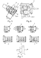
- Fig. 1
- eine erfindungsgemäße Brennkraftmaschine mit einem Abgasturbolader und einer Ventileinrichtung zur Regelung/Steuerung einer Abgasrückführrate im Bereich der Abzweigung einer Abgasrückführleitung aus dem Abgasstrang,
- Fig. 2
- eine mögliche erste Ausführungsform der Ventileinrichtung mit einem axial verstellbaren Kolben,
- Fig. 3
- eine Schnittdarstellung durch die Ventileinrichtung,
- Fig. 4a-c
- unterschiedliche Schaltzustände der gemäß den
Figuren 2 und 3 gezeigten Ventileinrichtung, - Fig. 5
- eine weitere alternative Ausführungsform der erfindungsgemäßen Ventileinrichtung mit einem drehbaren Ventilelement,
- Fig. 6
- eine Schnittdarstellung durch die Ventileinrichtung,
- Fig. 7a-c
- die gemäß den
Figuren 5 und 6 dargestellte Ventileinrichtungen bei unterschiedlichen Schaltzuständen, - Fig. 7d
- ein verdrehbares Ventilelement mit unterschiedlichen Radien im Bereich des zweiten Abgaskanals und des Abgasrückführkanals,
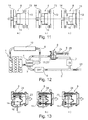
- Fig. 8
- eine weitere alternative Ausführungsform der erfindungsgemäßen Ventileinrichtung mit einer schwenkbaren Klappe,
- Fig. 9
- eine Schnittdarstellung durch die Ventileinrichtung gemäß der
Fig. 8 , - Fig. 10a-c
- unterschiedliche Schaltzustände der gemäß den
Figuren 8 und 9 gezeigten Ventileinrichtung, - Fig. 11 a-c
- unterschiedliche Schaltzustände einer Ventileinrichtung mit einem axial verstellbaren Kolben, der unterschiedliche Radien aufweist,
- Fig. 12
- eine erfindungsgemäße Brennkraftmaschine mit einer Ventileinrichtung zur Regelung/Steuerung einer Abgasrückführrate im Bereich der Einmündung der Abgasrückführleitung in den Ansaugstrang,
- Fig. 13 a-c
- unterschiedliche Schaltzustände einer Ventileinrichtung im Bereich der Einmündung der Abgasrückführleitung in den Ansaugstrang.
- Entsprechend der
Fig. 1 , weist eine erfindungsgemäße aufgeladene Brennkraftmaschine 1 einen Abgasturbolader 2 mit einer Turbine 3 und einem Verdichter 4 auf. Der Abgasturbolader 2 ist dabei turbinenseitig in einen Abgasstrang 5 und verdichterseitig in eine Ansaugstrang 6 der Brennkraftmaschine 1 eingebunden, wobei zusätzlich eine den Abgasstrang 5 und den Ansaugstrang 6 verbindende Abgasrückführleitung 7 vorgesehen ist. Erfindungsgemäß zweigt nun die Abgasrückführleitung 7 stromab der Turbine 3 des Abgasturboladers 2 aus dem Abgasstrang 5 ab und mündet stromauf des Verdichters 4 in den Ansaugstrang 6 ein. Zusätzlich ist im Bereich der Abgasrückführleitung 7 eine Ventileinrichtung 8 zur Steuerung/Regelung einer Abgasrückführrate angeordnet. - Durch die Anordnung der Abgasrückführleitung 7 stromab der Turbine 3 des Abgasturboladers 2 ist diese im Niederdruckbereich angeordnet, in welchem die Abgase üblicherweise eine deutlich geringere Temperatur aufweisen, sodass diese vor einer erneuten Zuführung in die Brennkraftmaschine 1 nicht oder nicht so stark gekühlt werden müssen, wie dies bei einer Hochdruck-Abgasrückführung, d. h. bei einer Abgasrückführung stromauf der Turbine 3 der Fall wäre. Generell erfüllt dabei die Abgasrückführung den Zweck, die von der Brennkraftmaschine 1 insgesamt ausgestoßenen NOx-Emissionen zu reduzieren, was ohne die Abgasrückführung, d. h. ausschließlich mit entsprechenden SCR-und NOx-Speicherkatalysatoren nicht ausreichend darstellbar wäre. Durch die Entnahme der rückzuführenden Abgase aus dem Niederdruckbereich, d. h. stromab der Turbine 3 des Abgasturboladers 2, steht der Turbine 3 noch der gesamte von der Brennkraftmaschine 1 kommende Abgasmassenstrom zur Verfügung, sodass diese eine vergleichsweise hohe Verdichterleistung erzeugen kann, was bei einer Abgasentnahme stromauf der Turbine 3 nicht der Fall wäre. Mit der erfindungsgemäßen Ventileinrichtung 8 lässt sich nicht nur die Abgasrückführrate, d. h. der Abgasrückführ-Massenstrom, sondern zugleich auch ein Abgasgegendruck regeln bzw. steuern, was bisher von im Abgasstrang 5 angeordneten Drosselklappen bewerkstelligt werden musste. Derartige Drosselklappen erlauben jedoch eine im Vergleich zur erfindungsgemäßen Ventileinrichtung 8 nur deutlich ungenauere Regelung/Steuerung und sprechen zudem nicht so schnell an, wie die erfindungsgemäße Ventileinrichtung 8, da sich bei einem Schließen der im Abgasstrang 5 angeordneten Drosselklappe zunächst ein entsprechender Abgasdruck aufbauen muss. Von besonderem Vorteil jedoch ist, dass die im Niederdruckbereich rückgeführten Abgase eine deutlich geringere Abgastemperatur aufweisen und dadurch vor einer erneuten Zuführung zur Verbrennung in der Brennkraftmaschine 1 deutlich weniger Kühlenergie bedürfen.
- Zwischen der Turbine 3 des Abgasturboladers 2 und der Ventileinrichtung 8 kann darüber hinaus ein Filter 9, bspw. ein Dieselpartikelfilter, angeordnet sein, der eine auf die Ventileinrichtung 8 wirkende Verschmutzung reduziert. Zwischen dem Verdichter 4 und der Brennkraftmaschine 1 kann zudem ein Ladeluftkühler 10 angeordnet sein, der die zur Verbrennung in der Brennkraftmaschine 1 bereitgestellte Ladeluft kühlt und dadurch je Verbrennungsvorgang mehr Luft zuführen kann. Eine entsprechende Einrichtung in der Form eines Abgaskühlers 11 kann auch zwischen der Ventileinrichtung 8 und dem Ansaugstrang 6 angeordnet sein, insbesondere im Bereich der Abgasrückführleitung 7.
- Generell kann die Ventileinrichtung 8 im Bereich der Abzweigung der Abgasrückführleitung 7 aus dem Abgasstrang 5 angeordnet sein (vgl.
Fig. 1 ) oder aber im Bereich der Einmündung der Abgasrückführleitung 7 in den Ansaugstrang 6 (vgl.Fig., 12 ). Alternativ ist auch vorstellbar, dass die Ventileinrichtung 8 im Bereich des Filters 9 oder im Bereich des Abgaskühlers 11, und insbesondere als integraler Bestandteil in diesen Bauteilen, angeordnet ist. - Für die nachfolgend beschriebenen Ausführungsformen der erfindungsgemäßen Ventileinrichtung 8 gilt, dass sich der Abgasstrang 5 im Bereich der Ventileinrichtung 8 in einen ersten Abgaskanal 12, einen zweiten Abgaskanal 13 sowie einen Abgasrückführkanal 14 aufteilt, wobei der Abgasrückführkanal 14 kommunizierend mit der Abgasrückführleitung 7 verbunden ist. Die Ventileinrichtung 8 ist dabei je nach Stellung zum zumindest teilweisen Verschließen des zweiten Abgaskanals 13 oder des Abgasrückführkanals 14 ausgebildet, wogegen der erste Abgaskanal 12 in keiner Stellung verschlossen wird, sodass stets ein zumindest geringer Abgasstrom über den ersten Abgaskanal 12 nach außen abgeführt wird.
- In den
Fig. 2 bis 4 ist eine erste mögliche Ausführungsform der erfindungsgemäßen Ventileinrichtung 8 dargestellt, die in diesem Fall einen verstellbaren Ventilkolben 15 aufweist, der zur Steuerung/Regelung der Abgasrückführrate in Axialrichtung verstellbar ist. Dieser Ventilkolben 15 kann bspw. aus Keramik ausgebildet sein und dadurch eine vergleichsweise glatte Oberfläche aufweisen, die ein Anhaften von unerwünschten Ablagerungen zumindest erschwert, vorzugsweise verhindert. Ein derartig glatter Ventilkolben 15 besitzt auch einen nicht zu unterschätzenden Reinigungseffekt, da er beim Hin- und Herverstellen an seiner Mantelfläche abgestreift wird. Generell ist der Ventilkolben 15 zwischen zumindest drei Stellungen (vgl. dieFiguren 4a-c ) verstellbar, nämlich einer gemäß derFig. 4c gezeigten ersten Stellung, in der er den zweiten Abgaskanal 13 verschließt, wogegen der erste Abgaskanal 12 und der Abgasrückführkanal 14 vollständig geöffnet sind. In dieser Stellung erfolgt eine vergleichsweise hohe Abgasrückführrate, da der aus dem Abgasstrang 5 eintreffende Abgasmassenstrom nur auf den ersten Abgaskanal 12 und den Abgasrückführkanal 14 aufgeteilt wird. In einer zweiten Stellung, die gemäß derFig. 4b dargestellt ist, öffnet der Ventilkolben 15 sowohl den ersten und zweiten Abgaskanal 12,13 als auch den Abgasrückführkanal 14, sodass auch in dieser Stellung eine Abgasrückführung erfolgt, die Abgasrückführrate jedoch unter der der ersten Stellung liegt. Gemäß derFig. 4a schließlich ist eine dritte Stellung dargestellt, in der der Ventilkolben 15 den Abgasrückführkanal 14 verschließt, wogegen der erste und zweite Abgaskanal 12,13 vollständig geöffnet sind, sodass in diesem Fall keine Abgasrückführung erfolgt. Neben den gemäß denFiguren 4a bis 4c gezeigten Stellungen sind selbstverständlich auch Zwischenstellungen zur besonders feinen Steuerung/Regelung der Abgasrückführrate vorstellbar, sodass der Ventilkolben 15 bspw. lediglich teilweise in den Abgasrückführkanal 14 hineinragt und dadurch diesen nicht vollständig, sondern lediglich teilweise verschließt. - Die
Fig. 4b zeigt dabei die zweite Stellung des Ventilkolbens 15, in welcher sich dieser bspw. ohne Bestromung eines entsprechenden Stellantriebs 16, bspw. eines Elektromotors, befindet. Der Ventilkolben 15 ist dabei über ein Lager 17 gelagert und wird mittels einer Kolbenstange 18 verstellt. Das Lager 17 ist dabei über eine entsprechende Dichtung 19 gegenüber dem abgasführenden Teil der Ventileinrichtung 8 abgedichtet. - Betrachtet man die Ventileinrichtungen 8 gemäß den
Fig. 5 bis 7 , so kann man erkennen, dass die Ventileinrichtung 8 in den dort gezeigten Ausführungsformen ein drehbares Ventilelement 20 in der Art eines Ventilzylinders 21 aufweist, welches ebenfalls selbstverständlich aus Metall oder aus Keramik ausgebildet sein kann. Auch in diesem Fall besitzt die Ausbildung des Ventilelements 20 aus Keramik den großen Vorteil einer glatten Oberfläche und dadurch einer reduzierten Neigung für unerwünschte Anlagerungen. Wie in der Ventileinrichtung 8 gemäß denFig. 2 bis 4 , ist das Ventilelement 20 trotz der Beeinflussung eines Massenstroms im zweiten Abgaskanal 13 sowie im Abgasrückführkanal 14 ausgebildet. - Gemäß den
Figuren 7a bis 7c sind dabei wiederum die drei Extremalstellungen der Ventileinrichtung 8 gezeigt, wobei in der gemäß derFig. 7c gezeigten ersten Stellung das Ventilelement 20 den zweiten Abgaskanal 13 verschließt, wogegen der erste Abgaskanal 12 und der Abgasrückführkanal 14 vollständig geöffnet sind. In der gemäß derFig. 7b gezeigten zweiten Stellung hingegen öffnet das Ventilelement 20 sämtliche Kanäle 12,13 und 14 jeweils vollständig. In der gemäß derFig. 7a gezeigten dritten Stellung hingegen, verschließt das verdrehbare Ventilelement 20 den Abgasrückführkanal 14, wogegen der erste und der zweite Abgaskanal 12,13 vollständig geöffnet sind, sodass in diesem Fall keine Abgasrückführung erfolgt. Gemäß derFig. 7b erfolgt eine im Vergleich zurFig. 7c reduzierte Abgasrückführung, wogegen gemäß derFig. 7c die maximal mögliche Abgasrückführung erfolgt. Wie bei den Ausführungen zu der Ventileinrichtung 8 gemäß denFig. 2 bis 4 , sind auch bei der Ventileinrichtung 8 gemäß denFig. 5 bis 7 unterschiedlichste Zwischenstellungen des drehbaren Ventilelements 20 denkbar, sodass neben den gemäß denFig. 7a bis 7c gezeigten Extremalstellungen auch beliebige Zwischenstellungen zur exakten Dosierung der Abgasrückführrate darstellbar sind. - Betrachtet man die
Figuren 7a bis 7c , so kann man zudem erkennen, dass der erste Abgaskanal 12 einen größeren Querschnitt aufweist, als bspw. der zweite Abgaskanal 13 oder der Abgasrückführkanal 14. In dieser Weise kann selbstverständlich auch das Ventilelement 20 ausgebildet sein, wie dies bspw. gemäß derFig. 7d dargestellt ist, sodass bspw. ein Durchmesser des als Ventilzylinders 21 ausgebildeten Ventilelements 20 im Bereich des zweiten Abgaskanals 13 deutlich größer ist als im Bereich des Abgasrückführkanals 14. - Gemäß den
Figuren 8 bis 10 schließlich ist eine weitere alternative Ausführungsform der Ventileinrichtung 8 gezeigt, wobei in diesem Fall das Ventilelement 20 als Klappe 22 ausgebildet ist. In der gemäß derFig. 10c dargestellten Extremalstellung, welche zugleich die erste Stellung darstellt, verschließt das Ventilelement 20, d. h. die Klappe 22 den zweiten Abgaskanal 13, wogegen der erste Abgaskanal 12 und der Abgasrückführkanal 14 geöffnet sind. In der gemäß derFig. 10b dargestellten Stellung hingegen sind sämtliche Kanäle 12,13 und 14 geöffnet. In der gemäß derFig. 10a dargestellten dritten Stellung verschließt das Ventilelement 20, d. h. die Klappe 22 den Abgasrückführkanal 14 vollständig, wogegen der erste und zweite Abgaskanal 12,13 geöffnet sind. In diesem Fall findet somit wiederum keine Abgasrückführung statt. - In den
Fig. 11a bis 11c ist eine weitere mögliche Ausführungsform der Ventileinrichtung 8 dargestellt, die in diesem Fall einen verstellbaren Ventilkolben 15 mit unterschiedlichen Radien aufweist, der zur Steuerung/Regelung der Abgasrückführrate in Axialrichtung verstellbar ist. Dieser Ventilkolben 15 kann bspw. aus Keramik ausgebildet sein und dadurch eine vergleichsweise glatte Oberfläche aufweisen, die ein Anhaften von unerwünschten Ablagerungen zumindest erschwert, vorzugsweise verhindert. Generell ist der Ventilkolben 15 zwischen zumindest drei Stellungen (vgl. dieFiguren 11a-c ) verstellbar, nämlich einer gemäß derFig. 11c gezeigten ersten Stellung, in der er den zweiten Abgaskanal 13 verschließt, wogegen der erste Abgaskanal 12 und der Abgasrückführkanal 14 vollständig geöffnet sind. In dieser Stellung erfolgt eine vergleichsweise hohe Abgasrückführrate, da der aus dem Abgasstrang 5 eintreffende Abgasmassenstrom nur auf den ersten Abgaskanal 12 und den Abgasrückführkanal 14 aufgeteilt wird. In einer zweiten Stellung, die gemäß derFig. 11b dargestellt ist, öffnet der Ventilkolben 15 sowohl den ersten und zweiten Abgaskanal 12,13 als auch den Abgasrückführkanal 14, sodass auch in dieser Stellung eine Abgasrückführung erfolgt, die Abgasrückführrate jedoch unter der der ersten Stellung liegt. Gemäß derFig. 11 a schließlich ist eine dritte Stellung dargestellt, in der der Ventilkolben 15 den Abgasrückführkanal 14 verschließt, wogegen der erste und zweite Abgaskanal 12,13 vollständig geöffnet sind, sodass in diesem Fall keine Abgasrückführung erfolgt. Neben den gemäß denFiguren 11a bis 11c gezeigten Stellungen sind selbstverständlich auch Zwischenstellungen zur besonders feinen Steuerung/Regelung der Abgasrückführrate vorstellbar, sodass der Ventilkolben 15 bspw. lediglich teilweise in den Abgasrückführkanal 14 hineinragt und dadurch diesen nicht vollständig, sondern lediglich teilweise verschließt. - Der erste Abgaskanal 12 ist dabei gemäß den
Fig. 11a-c mit unterbrochener Linie gezeichnet, was bedeuten soll, dass dieser rein optional vorgesehen ist. In diesem Fall wären nur der zweite Abgaskanal 13 und der Abgasrückführkanal 14 vorhanden, die beide von dem Ventilkolben 15 komplett verschließbar wären. Der zweite Abgaskanal 13 weist einen deutlich größeren Querschnitt auf als der Abgasrückführkanal 14, so dass der Ventilkolben 15 in diesem Bereich einen deutlich größeren Durchmesser aufweist als im Bereich des Abgasrückführkanals. Die gezeigte Ventileinrichtung 8 kann selbstverständlich auch im Einmündungsbereich der Abgasrückführleitung 7 in den Ansaugstrang 6 angeordnet sein, wobei in diesem Fall dann in der ersten und zweiten Abgasleitung 12,13 kein Abgas, sondern Frischluft aus dem Ansaugstrang 6 strömen würde. - Eine derartige Anordnung der Ventileinrichtung 8 ist in
Fig. 12 und Fig. 13 gezeigt. Gemäß denFig. 13a bis 13c ist eine Ventileinrichtung 8 im Bereich der Einmündung der Abgasrückführleitung 7 in dem Ansaugstrang 6 dargestellt, die wiederum einen verstellbaren Ventilkolben 15 aufweist, der zur Steuerung/Regelung der Abgasrückführrate in Axialrichtung verstellbar ist. Generell ist der Ventilkolben 15 zwischen zumindest drei Stellungen (vgl. dieFiguren 13a-c ) verstellbar, nämlich einer gemäß derFig. 13c gezeigten ersten Stellung, in der er einen zweiten Frischluftkanal 23 verschließt, wogegen der erste Frischluftkanal 24 und der Abgasrückführkanal 14 vollständig geöffnet sind. In dieser Stellung erfolgt eine vergleichsweise hohe Abgasrückführrate. In einer zweiten Stellung, die gemäß derFig. 13b dargestellt ist, öffnet der Ventilkolben 15 sowohl den ersten und zweiten Frischluftkanal 24,23 als auch den Abgasrückführkanal 14, sodass auch in dieser Stellung eine Abgasrückführung erfolgt, die Abgasrückführrate jedoch unter der der ersten Stellung liegt. Gemäß derFig. 13a schließlich ist eine dritte Stellung dargestellt, in der der Ventilkolben 15 den Abgasrückführkanal 14 verschließt, wogegen der erste und zweite Frischluftkanal 24,23 vollständig geöffnet sind, sodass in diesem Fall keine Abgasrückführung erfolgt. Neben den gezeigten Extremalstellungen sind selbstverständlich auch wieder Zwischenstellungen zur besonders feinen Steuerung/Regelung der Abgasrückführrate vorstellbar. - Bei der Anordnung der Ventileinrichtung 8 im Bereich der Einmündung der Abgasrückführleitung 7 in den Ansaugstrang 6 erhält diese eine neue Funktion, d.h. die Ventileinrichtung 8 steuert und regelt nicht nur den Abgasrückführmassenstrom, sondern auch den Ansaugdruck im Ansaugstrang 6. bei einem Vorsehen einer Drosselklappe 25,25' im Ansaugstrang 6 und/oder im Abgasstrang 5 kann zusätzlich Einfluss auf die rückführbare Abgasmenge genommen werden. Mit der erfindungsgemäßen Ventileinrichtung 8 kann auf derartige Drosselklappen aber generelle auch verzichtet werden.
- Mit den unterschiedlichsten Ausführungsformen der erfindungsgemäßen Ventileinrichtung 8 ist eine besonders exakte Steuerung/Regelung der Abgasrückführrate im Niederdruckbereich, d. h. stromab der Turbine 3 des Abgasturboladers 2 möglich, was mit bisherigen im Abgasstrang 5 angeordneten Drosselklappen so nicht möglich war. Zugleich ist auch eine Temperatursteuerung möglich. Sämtliche der gezeigten Ausführungsformen der Ventileinrichtung 8 besitzen einen geringen Bauraumbedarf, was ebenfalls einen großen Vorteil darstellt. Insbesondere die Ventileinrichtungen 8 gemäß den
Figuren 2 bis 7 erzeugen dabei zudem einen geringen Druckverlust, da bei geöffnetem zweiten Abgaskanal 13 bzw. geöffnetem Abgasrückführkanal 14 das jeweilige Ventilelement 20,21,22 bzw. der Ventilkolben 15 nicht in einen Strömungsquerschnitt hineinragt. Durch die Ausführung aus Keramik werden zudem unerwünschte Ablagerungen durch die extrem glatte Oberfläche reduziert.
Claims (4)
- Aufgeladene Brennkraftmaschine (1) mit einem Abgasturbolader (2), der turbinenseitig in einen Abgasstrang (5) und verdichterseitig in einen Ansaugstrang (6) eingebunden ist, und wobei eine den Abgasstrang (5) und den Ansaugstrang (6) verbindende Abgasrückführleitung (7) vorgesehen ist, wobei die Abgasrückführleitung (7) stromab der Turbine (3) des Abgasturboladers (2) aus dem Abgasstrang (5) abzweigt und stromauf des Verdichters (4) in den Ansaugstrang (6) mündet, wobei im Bereich der Abgasrückführleitung (7) eine Ventileinrichtung (8) zur Steuerung/Regelung einer Abgasrückführrate angeordnet ist,
dadurch gekennzeichnet, dass- die Ventileinrichtung (8) einen verstellbaren Ventilkolben (15) aufweist, der zur Steuerung/Regelung der Abgasrückführrate in Axialrichtung verstellbar ist,- sich der Abgasstrang (5) im Bereich der Ventileinrichtung (8) in einen ersten Abgaskanal (12), einen zweiten Abgaskanal (13) sowie einen Abgasrückführkanal (14) aufteilt, wobei die Ventileinrichtung (8) zum Verschließen des zweiten Abgaskanals (13) oder des Abgasrückführkanals (14) ausgebildet ist,- der Ventilkolben (15) zumindest zwischen drei Stellungen verstellbar ist, nämlich- einer ersten Stellung, in welcher er den zweiten Abgaskanal (13) verschließt, wogegen der erste Abgaskanal (12) und der Abgasrückführkanal (14) vollständig geöffnet sind,- einer zweiten Stellung, in welcher er den ersten und zweiten Abgaskanal (12,13) und den Abgasrückführkanal (14) vollständig öffnet,- einer dritten Stellung, in welcher er den Abgasrückführkanal (14) schließt, wogegen der erste und zweite Abgaskanal (12,13) vollständig geöffnet sind. - Brennkraftmaschine nach Anspruch 1,
dadurch gekennzeichnet, dass- zwischen der Turbine (3) des Abgasturboladers (2) und der Ventileinrichtung (8) ein Filter (9), insbesondere ein Dieselpartikelfilter angeordnet ist, und/oder- dass zwischen dem Verdichter (4) und der Brennkraftmaschine (1) ein Ladeluftkühler (10) angeordnet ist, und/oder- dass zwischen der Ventileinrichtung (8) und dem Abgasstrang (5) ein Abgaskühler (11) angeordnet ist. - Brennkraftmaschine nach Anspruch 2,
dadurch gekennzeichnet, dass- dass die Ventileinrichtung (8) im Bereich der Abzweigung der Abgasrückführleitung (7) aus dem Abgasstrang (5) angeordnet ist, oder- dass die Ventileinrichtung (8) im Bereich der Einmündung der Abgasrückführleitung (7) in den Ansaugstrang (6) angeordnet ist, oder- dass die Ventileinrichtung (8) im Bereich des Filters (9), insbesondere in diesem angeordnet ist, oder- dass die Ventileinrichtung (8) im Bereich des Ladeluftkühlers (10) angeordnet ist. - Brennkraftmaschine nach einem der Ansprüche 1 bis 3,
dadurch gekennzeichnet, dass
der Ventilkolben (15) aus Keramik ausgebildet ist.
Applications Claiming Priority (3)
| Application Number | Priority Date | Filing Date | Title |
|---|---|---|---|
| DE102011080101 | 2011-07-29 | ||
| DE102011080965A DE102011080965A1 (de) | 2011-07-29 | 2011-08-15 | Aufgeladene Brennkraftmaschine |
| PCT/EP2012/064703 WO2013017524A1 (de) | 2011-07-29 | 2012-07-26 | Aufgeladene brennkraftmaschine |
Publications (2)
| Publication Number | Publication Date |
|---|---|
| EP2737195A1 EP2737195A1 (de) | 2014-06-04 |
| EP2737195B1 true EP2737195B1 (de) | 2015-09-16 |
Family
ID=47502940
Family Applications (1)
| Application Number | Title | Priority Date | Filing Date |
|---|---|---|---|
| EP12745438.7A Not-in-force EP2737195B1 (de) | 2011-07-29 | 2012-07-26 | Aufgeladene brennkraftmaschine |
Country Status (6)
| Country | Link |
|---|---|
| US (1) | US9371772B2 (de) |
| EP (1) | EP2737195B1 (de) |
| JP (1) | JP5905093B2 (de) |
| CN (1) | CN103748348B (de) |
| DE (1) | DE102011080965A1 (de) |
| WO (1) | WO2013017524A1 (de) |
Families Citing this family (2)
| Publication number | Priority date | Publication date | Assignee | Title |
|---|---|---|---|---|
| CN104806345B (zh) * | 2015-04-10 | 2017-08-04 | 中国第一汽车股份有限公司无锡油泵油嘴研究所 | 一种发动机电动气体配给装置 |
| KR101664069B1 (ko) * | 2015-05-07 | 2016-10-10 | 현대자동차 주식회사 | 저압 이지알 시스템을 갖는 엔진 및 이의 제어방법 |
Family Cites Families (17)
| Publication number | Priority date | Publication date | Assignee | Title |
|---|---|---|---|---|
| EP0075360B1 (de) | 1981-09-22 | 1986-08-27 | BBC Aktiengesellschaft Brown, Boveri & Cie. | Verfahren zur Aufladung von Verbrennungsmotoren durch Abgaslader mit variablem Abgasschluckvermögen und nach diesem Verfahren arbeitender Verbrennungsmotor |
| JPH06108923A (ja) * | 1992-09-25 | 1994-04-19 | Isuzu Motors Ltd | 排気還流制御装置 |
| US5822958A (en) * | 1997-06-02 | 1998-10-20 | Winpak Lane, Inc. | Sanitary fill tube and piston valve assembly for a pouch packaging machine |
| US6006732A (en) * | 1998-09-03 | 1999-12-28 | Navistar International Transportation Corp | Balanced flow EGR control apparatus |
| US6220233B1 (en) * | 1999-10-13 | 2001-04-24 | Caterpillar Inc. | Exhaust gas recirculation system having variable valve timing and method of using same in an internal combustion engine |
| US6422217B1 (en) * | 2000-12-19 | 2002-07-23 | Caterpillar Inc. | Back pressure valve drive EGR system |
| DE10222917B4 (de) * | 2002-05-24 | 2007-12-20 | Man Nutzfahrzeuge Ag | Aufgeladene Brennkraftmaschine |
| JP2008530423A (ja) * | 2005-02-07 | 2008-08-07 | ボーグワーナー・インコーポレーテッド | ディーゼルエンジン用の排気スロットルegr弁モジュール |
| JP4396581B2 (ja) * | 2005-06-02 | 2010-01-13 | 株式会社デンソー | 内燃機関のegr制御装置 |
| KR20090034374A (ko) * | 2006-08-04 | 2009-04-07 | 보르그워너 인코퍼레이티드 | 배기 브리딩 시스템용 다기능 밸브 |
| DE102008005400A1 (de) | 2007-01-19 | 2008-07-24 | Behr Thermot-Tronik Gmbh | Wärmeübertragerventileinrichtung |
| DE102007048297A1 (de) * | 2007-10-08 | 2009-04-09 | Behr Gmbh & Co. Kg | Ventilvorrichtung zur Regelung eines rückgeführten gasförmigen Fluids, Wärmetauscher, Verfahren zur Regelung einer Ventilvorrichtung und/oder zur Regelung eines Wärmetauschers |
| DE102008048912B4 (de) * | 2008-09-26 | 2021-11-04 | Faurecia Emissions Control Technologies, Germany Gmbh | Abgasanlage und Abgasventil zur Steuerung eines Volumenstroms von Abgas sowie ein Verfahren zur Steuerung eines Volumenstroms |
| IT1396027B1 (it) * | 2009-10-19 | 2012-11-09 | Dellorto Spa | Valvola egr per applicazioni di tipo low pressure, nella tecnica del ricircolo controllato di gas combusti in motori a combustione interna. |
| US7987837B2 (en) | 2010-02-16 | 2011-08-02 | Ford Global Technologies, Llc | Exhaust treatment system for internal combustion engine |
| KR20130060186A (ko) * | 2010-04-14 | 2013-06-07 | 보르그워너 인코퍼레이티드 | 다기능 밸브 |
| DE102011016630A1 (de) * | 2011-04-09 | 2012-10-11 | Volkswagen Aktiengesellschaft | Stellvorrichtung und Abgasstrang |
-
2011
- 2011-08-15 DE DE102011080965A patent/DE102011080965A1/de not_active Withdrawn
-
2012
- 2012-07-26 CN CN201280034202.7A patent/CN103748348B/zh not_active Expired - Fee Related
- 2012-07-26 WO PCT/EP2012/064703 patent/WO2013017524A1/de active Application Filing
- 2012-07-26 EP EP12745438.7A patent/EP2737195B1/de not_active Not-in-force
- 2012-07-26 JP JP2014523292A patent/JP5905093B2/ja active Active
- 2012-07-26 US US14/235,791 patent/US9371772B2/en not_active Expired - Fee Related
Also Published As
| Publication number | Publication date |
|---|---|
| US9371772B2 (en) | 2016-06-21 |
| DE102011080965A1 (de) | 2013-01-31 |
| CN103748348B (zh) | 2016-04-27 |
| US20140283796A1 (en) | 2014-09-25 |
| JP5905093B2 (ja) | 2016-04-20 |
| WO2013017524A1 (de) | 2013-02-07 |
| EP2737195A1 (de) | 2014-06-04 |
| JP2014521871A (ja) | 2014-08-28 |
| CN103748348A (zh) | 2014-04-23 |
Similar Documents
| Publication | Publication Date | Title |
|---|---|---|
| EP1763627B1 (de) | Brennkraftmaschine mit abgasnachbehandlung und verfahren zu deren betrieb | |
| EP2503126B1 (de) | Mit Waste-Gate-Turbinen ausgestattete Brennkraftmaschine und Verfahren zum Betreiben einer derartigen Brennkraftmaschine | |
| EP2108807B1 (de) | Abgasrückführsystem für eine Verbrennungskraftmaschine | |
| AT512567B1 (de) | Funktionsmodul mit einem Abgasturbolader und einem Abgaskrümmer | |
| EP2267291A2 (de) | Kolbenmotor und Betriebsverfahren | |
| EP2134943A1 (de) | Turboaufgeladene brennkraftmaschine und verfahren | |
| DE102007060415A1 (de) | Brennkraftmaschine und Verfahren zum Steuern einer Brennkraftmaschine für ein Kraftfahrzeug | |
| EP1455078B1 (de) | Brennkraftmaschine mit einem Abgasturbolader und einem Abgasrückführsystem | |
| DE102009004418A1 (de) | Verfahren zur Nachbehandlung eines Abgasstroms einer mehrzylindrigen Brennkraftmaschine eines Fahrzeuges sowie Abgasnachbehandlungsvorrichtung | |
| DE202017105126U1 (de) | Abgasleitsystem | |
| DE102008048681A1 (de) | Brennkraftmaschine mit zwei Ladern und Verfahren zum Betreiben derselben | |
| DE102009004417A1 (de) | Verfahren zur Nachbehandlung eines Abgasstroms einer mehrzylindrigen Brennkraftmaschine eines Fahrzeuges sowie Abgasnachbehandlungsvorrichtung | |
| DE102008056337A1 (de) | Brennkraftmaschine mit Abgasrückführung | |
| WO2006111280A1 (de) | Brennkraftmaschine mit abgasrückführung | |
| DE102009006013A1 (de) | Abgasklappenvorrichtung und Abgaswärmerückgewinnungssystem einer Verbrennungskraftmaschine | |
| DE112007000298B4 (de) | Auspuffelement für Anlage zum Ausströmen von Gasen | |
| DE102017119537B4 (de) | Abgasleitsystem | |
| EP2737195B1 (de) | Aufgeladene brennkraftmaschine | |
| WO2010128040A1 (de) | Brennkraftmaschine und zugehöriges betriebsverfahren | |
| DE102007025437A1 (de) | Verfahren für eine Brennkraftmaschine mit einem Abgasturbolader | |
| DE102010045503A1 (de) | Vorrichtung zur Abgasrückführung an einer Brennkraftmaschine | |
| DE102015200045A1 (de) | Verfahren zum optimierten Betreiben einer Brennkraftmaschine und Brennkraftmaschine zur Durchführung eines derartigen Verfahrens | |
| DE102016015357A1 (de) | Drosseleinrichtung für einen Abgastrakt einer Verbrennungskraftmaschine | |
| DE102011120168A1 (de) | Verdichter für einen Abgasturbolader | |
| DE102013020448A1 (de) | Verfahren zum Betreiben eines Kraftwagens |
Legal Events
| Date | Code | Title | Description |
|---|---|---|---|
| PUAI | Public reference made under article 153(3) epc to a published international application that has entered the european phase |
Free format text: ORIGINAL CODE: 0009012 |
|
| 17P | Request for examination filed |
Effective date: 20140123 |
|
| AK | Designated contracting states |
Kind code of ref document: A1 Designated state(s): AL AT BE BG CH CY CZ DE DK EE ES FI FR GB GR HR HU IE IS IT LI LT LU LV MC MK MT NL NO PL PT RO RS SE SI SK SM TR |
|
| DAX | Request for extension of the european patent (deleted) | ||
| GRAP | Despatch of communication of intention to grant a patent |
Free format text: ORIGINAL CODE: EPIDOSNIGR1 |
|
| INTG | Intention to grant announced |
Effective date: 20150323 |
|
| GRAS | Grant fee paid |
Free format text: ORIGINAL CODE: EPIDOSNIGR3 |
|
| GRAA | (expected) grant |
Free format text: ORIGINAL CODE: 0009210 |
|
| AK | Designated contracting states |
Kind code of ref document: B1 Designated state(s): AL AT BE BG CH CY CZ DE DK EE ES FI FR GB GR HR HU IE IS IT LI LT LU LV MC MK MT NL NO PL PT RO RS SE SI SK SM TR |
|
| REG | Reference to a national code |
Ref country code: GB Ref legal event code: FG4D Free format text: NOT ENGLISH |
|
| REG | Reference to a national code |
Ref country code: CH Ref legal event code: EP |
|
| REG | Reference to a national code |
Ref country code: IE Ref legal event code: FG4D Free format text: LANGUAGE OF EP DOCUMENT: GERMAN |
|
| REG | Reference to a national code |
Ref country code: AT Ref legal event code: REF Ref document number: 750023 Country of ref document: AT Kind code of ref document: T Effective date: 20151015 |
|
| REG | Reference to a national code |
Ref country code: DE Ref legal event code: R096 Ref document number: 502012004597 Country of ref document: DE |
|
| REG | Reference to a national code |
Ref country code: NL Ref legal event code: MP Effective date: 20150916 |
|
| PG25 | Lapsed in a contracting state [announced via postgrant information from national office to epo] |
Ref country code: FI Free format text: LAPSE BECAUSE OF FAILURE TO SUBMIT A TRANSLATION OF THE DESCRIPTION OR TO PAY THE FEE WITHIN THE PRESCRIBED TIME-LIMIT Effective date: 20150916 Ref country code: GR Free format text: LAPSE BECAUSE OF FAILURE TO SUBMIT A TRANSLATION OF THE DESCRIPTION OR TO PAY THE FEE WITHIN THE PRESCRIBED TIME-LIMIT Effective date: 20151217 Ref country code: NO Free format text: LAPSE BECAUSE OF FAILURE TO SUBMIT A TRANSLATION OF THE DESCRIPTION OR TO PAY THE FEE WITHIN THE PRESCRIBED TIME-LIMIT Effective date: 20151216 Ref country code: LT Free format text: LAPSE BECAUSE OF FAILURE TO SUBMIT A TRANSLATION OF THE DESCRIPTION OR TO PAY THE FEE WITHIN THE PRESCRIBED TIME-LIMIT Effective date: 20150916 Ref country code: LV Free format text: LAPSE BECAUSE OF FAILURE TO SUBMIT A TRANSLATION OF THE DESCRIPTION OR TO PAY THE FEE WITHIN THE PRESCRIBED TIME-LIMIT Effective date: 20150916 |
|
| REG | Reference to a national code |
Ref country code: LT Ref legal event code: MG4D |
|
| PG25 | Lapsed in a contracting state [announced via postgrant information from national office to epo] |
Ref country code: SE Free format text: LAPSE BECAUSE OF FAILURE TO SUBMIT A TRANSLATION OF THE DESCRIPTION OR TO PAY THE FEE WITHIN THE PRESCRIBED TIME-LIMIT Effective date: 20150916 Ref country code: HR Free format text: LAPSE BECAUSE OF FAILURE TO SUBMIT A TRANSLATION OF THE DESCRIPTION OR TO PAY THE FEE WITHIN THE PRESCRIBED TIME-LIMIT Effective date: 20150916 Ref country code: RS Free format text: LAPSE BECAUSE OF FAILURE TO SUBMIT A TRANSLATION OF THE DESCRIPTION OR TO PAY THE FEE WITHIN THE PRESCRIBED TIME-LIMIT Effective date: 20150916 |
|
| PG25 | Lapsed in a contracting state [announced via postgrant information from national office to epo] |
Ref country code: NL Free format text: LAPSE BECAUSE OF FAILURE TO SUBMIT A TRANSLATION OF THE DESCRIPTION OR TO PAY THE FEE WITHIN THE PRESCRIBED TIME-LIMIT Effective date: 20150916 |
|
| PG25 | Lapsed in a contracting state [announced via postgrant information from national office to epo] |
Ref country code: IS Free format text: LAPSE BECAUSE OF FAILURE TO SUBMIT A TRANSLATION OF THE DESCRIPTION OR TO PAY THE FEE WITHIN THE PRESCRIBED TIME-LIMIT Effective date: 20160116 Ref country code: IT Free format text: LAPSE BECAUSE OF FAILURE TO SUBMIT A TRANSLATION OF THE DESCRIPTION OR TO PAY THE FEE WITHIN THE PRESCRIBED TIME-LIMIT Effective date: 20150916 Ref country code: CZ Free format text: LAPSE BECAUSE OF FAILURE TO SUBMIT A TRANSLATION OF THE DESCRIPTION OR TO PAY THE FEE WITHIN THE PRESCRIBED TIME-LIMIT Effective date: 20150916 Ref country code: ES Free format text: LAPSE BECAUSE OF FAILURE TO SUBMIT A TRANSLATION OF THE DESCRIPTION OR TO PAY THE FEE WITHIN THE PRESCRIBED TIME-LIMIT Effective date: 20150916 Ref country code: EE Free format text: LAPSE BECAUSE OF FAILURE TO SUBMIT A TRANSLATION OF THE DESCRIPTION OR TO PAY THE FEE WITHIN THE PRESCRIBED TIME-LIMIT Effective date: 20150916 Ref country code: SK Free format text: LAPSE BECAUSE OF FAILURE TO SUBMIT A TRANSLATION OF THE DESCRIPTION OR TO PAY THE FEE WITHIN THE PRESCRIBED TIME-LIMIT Effective date: 20150916 |
|
| PG25 | Lapsed in a contracting state [announced via postgrant information from national office to epo] |
Ref country code: PT Free format text: LAPSE BECAUSE OF FAILURE TO SUBMIT A TRANSLATION OF THE DESCRIPTION OR TO PAY THE FEE WITHIN THE PRESCRIBED TIME-LIMIT Effective date: 20160118 Ref country code: RO Free format text: LAPSE BECAUSE OF FAILURE TO SUBMIT A TRANSLATION OF THE DESCRIPTION OR TO PAY THE FEE WITHIN THE PRESCRIBED TIME-LIMIT Effective date: 20150916 Ref country code: PL Free format text: LAPSE BECAUSE OF FAILURE TO SUBMIT A TRANSLATION OF THE DESCRIPTION OR TO PAY THE FEE WITHIN THE PRESCRIBED TIME-LIMIT Effective date: 20150916 |
|
| REG | Reference to a national code |
Ref country code: DE Ref legal event code: R097 Ref document number: 502012004597 Country of ref document: DE |
|
| PLBE | No opposition filed within time limit |
Free format text: ORIGINAL CODE: 0009261 |
|
| STAA | Information on the status of an ep patent application or granted ep patent |
Free format text: STATUS: NO OPPOSITION FILED WITHIN TIME LIMIT |
|
| REG | Reference to a national code |
Ref country code: FR Ref legal event code: PLFP Year of fee payment: 5 |
|
| 26N | No opposition filed |
Effective date: 20160617 |
|
| PG25 | Lapsed in a contracting state [announced via postgrant information from national office to epo] |
Ref country code: DK Free format text: LAPSE BECAUSE OF FAILURE TO SUBMIT A TRANSLATION OF THE DESCRIPTION OR TO PAY THE FEE WITHIN THE PRESCRIBED TIME-LIMIT Effective date: 20150916 |
|
| PG25 | Lapsed in a contracting state [announced via postgrant information from national office to epo] |
Ref country code: SI Free format text: LAPSE BECAUSE OF FAILURE TO SUBMIT A TRANSLATION OF THE DESCRIPTION OR TO PAY THE FEE WITHIN THE PRESCRIBED TIME-LIMIT Effective date: 20150916 |
|
| PG25 | Lapsed in a contracting state [announced via postgrant information from national office to epo] |
Ref country code: BE Free format text: LAPSE BECAUSE OF NON-PAYMENT OF DUE FEES Effective date: 20160731 |
|
| REG | Reference to a national code |
Ref country code: CH Ref legal event code: PL |
|
| PG25 | Lapsed in a contracting state [announced via postgrant information from national office to epo] |
Ref country code: MC Free format text: LAPSE BECAUSE OF FAILURE TO SUBMIT A TRANSLATION OF THE DESCRIPTION OR TO PAY THE FEE WITHIN THE PRESCRIBED TIME-LIMIT Effective date: 20150916 |
|
| PG25 | Lapsed in a contracting state [announced via postgrant information from national office to epo] |
Ref country code: LI Free format text: LAPSE BECAUSE OF NON-PAYMENT OF DUE FEES Effective date: 20160731 Ref country code: CH Free format text: LAPSE BECAUSE OF NON-PAYMENT OF DUE FEES Effective date: 20160731 |
|
| REG | Reference to a national code |
Ref country code: IE Ref legal event code: MM4A |
|
| REG | Reference to a national code |
Ref country code: FR Ref legal event code: PLFP Year of fee payment: 6 |
|
| PG25 | Lapsed in a contracting state [announced via postgrant information from national office to epo] |
Ref country code: IE Free format text: LAPSE BECAUSE OF NON-PAYMENT OF DUE FEES Effective date: 20160726 |
|
| PG25 | Lapsed in a contracting state [announced via postgrant information from national office to epo] |
Ref country code: LU Free format text: LAPSE BECAUSE OF NON-PAYMENT OF DUE FEES Effective date: 20160726 |
|
| PG25 | Lapsed in a contracting state [announced via postgrant information from national office to epo] |
Ref country code: HU Free format text: LAPSE BECAUSE OF FAILURE TO SUBMIT A TRANSLATION OF THE DESCRIPTION OR TO PAY THE FEE WITHIN THE PRESCRIBED TIME-LIMIT; INVALID AB INITIO Effective date: 20120726 Ref country code: SM Free format text: LAPSE BECAUSE OF FAILURE TO SUBMIT A TRANSLATION OF THE DESCRIPTION OR TO PAY THE FEE WITHIN THE PRESCRIBED TIME-LIMIT Effective date: 20150916 Ref country code: CY Free format text: LAPSE BECAUSE OF FAILURE TO SUBMIT A TRANSLATION OF THE DESCRIPTION OR TO PAY THE FEE WITHIN THE PRESCRIBED TIME-LIMIT Effective date: 20150916 |
|
| PG25 | Lapsed in a contracting state [announced via postgrant information from national office to epo] |
Ref country code: MT Free format text: LAPSE BECAUSE OF FAILURE TO SUBMIT A TRANSLATION OF THE DESCRIPTION OR TO PAY THE FEE WITHIN THE PRESCRIBED TIME-LIMIT Effective date: 20150916 Ref country code: MK Free format text: LAPSE BECAUSE OF FAILURE TO SUBMIT A TRANSLATION OF THE DESCRIPTION OR TO PAY THE FEE WITHIN THE PRESCRIBED TIME-LIMIT Effective date: 20150916 |
|
| REG | Reference to a national code |
Ref country code: FR Ref legal event code: PLFP Year of fee payment: 7 |
|
| PG25 | Lapsed in a contracting state [announced via postgrant information from national office to epo] |
Ref country code: BG Free format text: LAPSE BECAUSE OF FAILURE TO SUBMIT A TRANSLATION OF THE DESCRIPTION OR TO PAY THE FEE WITHIN THE PRESCRIBED TIME-LIMIT Effective date: 20150916 |
|
| PG25 | Lapsed in a contracting state [announced via postgrant information from national office to epo] |
Ref country code: TR Free format text: LAPSE BECAUSE OF FAILURE TO SUBMIT A TRANSLATION OF THE DESCRIPTION OR TO PAY THE FEE WITHIN THE PRESCRIBED TIME-LIMIT Effective date: 20150916 Ref country code: AL Free format text: LAPSE BECAUSE OF FAILURE TO SUBMIT A TRANSLATION OF THE DESCRIPTION OR TO PAY THE FEE WITHIN THE PRESCRIBED TIME-LIMIT Effective date: 20150916 |
|
| PGFP | Annual fee paid to national office [announced via postgrant information from national office to epo] |
Ref country code: FR Payment date: 20180726 Year of fee payment: 7 |
|
| PGFP | Annual fee paid to national office [announced via postgrant information from national office to epo] |
Ref country code: AT Payment date: 20180727 Year of fee payment: 7 Ref country code: GB Payment date: 20180731 Year of fee payment: 7 |
|
| PGFP | Annual fee paid to national office [announced via postgrant information from national office to epo] |
Ref country code: DE Payment date: 20180928 Year of fee payment: 7 |
|
| REG | Reference to a national code |
Ref country code: DE Ref legal event code: R119 Ref document number: 502012004597 Country of ref document: DE |
|
| REG | Reference to a national code |
Ref country code: AT Ref legal event code: MM01 Ref document number: 750023 Country of ref document: AT Kind code of ref document: T Effective date: 20190726 |
|
| GBPC | Gb: european patent ceased through non-payment of renewal fee |
Effective date: 20190726 |
|
| PG25 | Lapsed in a contracting state [announced via postgrant information from national office to epo] |
Ref country code: GB Free format text: LAPSE BECAUSE OF NON-PAYMENT OF DUE FEES Effective date: 20190726 Ref country code: DE Free format text: LAPSE BECAUSE OF NON-PAYMENT OF DUE FEES Effective date: 20200201 Ref country code: AT Free format text: LAPSE BECAUSE OF NON-PAYMENT OF DUE FEES Effective date: 20190726 |
|
| PG25 | Lapsed in a contracting state [announced via postgrant information from national office to epo] |
Ref country code: FR Free format text: LAPSE BECAUSE OF NON-PAYMENT OF DUE FEES Effective date: 20190731 |