EP2737195B1 - Moteur à combustion interne suralimenté - Google Patents
Moteur à combustion interne suralimenté Download PDFInfo
- Publication number
- EP2737195B1 EP2737195B1 EP12745438.7A EP12745438A EP2737195B1 EP 2737195 B1 EP2737195 B1 EP 2737195B1 EP 12745438 A EP12745438 A EP 12745438A EP 2737195 B1 EP2737195 B1 EP 2737195B1
- Authority
- EP
- European Patent Office
- Prior art keywords
- exhaust gas
- gas recirculation
- exhaust
- valve device
- valve
- Prior art date
- Legal status (The legal status is an assumption and is not a legal conclusion. Google has not performed a legal analysis and makes no representation as to the accuracy of the status listed.)
- Not-in-force
Links
Images


Classifications
-
- F—MECHANICAL ENGINEERING; LIGHTING; HEATING; WEAPONS; BLASTING
- F02—COMBUSTION ENGINES; HOT-GAS OR COMBUSTION-PRODUCT ENGINE PLANTS
- F02B—INTERNAL-COMBUSTION PISTON ENGINES; COMBUSTION ENGINES IN GENERAL
- F02B37/00—Engines characterised by provision of pumps driven at least for part of the time by exhaust
-
- F—MECHANICAL ENGINEERING; LIGHTING; HEATING; WEAPONS; BLASTING
- F02—COMBUSTION ENGINES; HOT-GAS OR COMBUSTION-PRODUCT ENGINE PLANTS
- F02M—SUPPLYING COMBUSTION ENGINES IN GENERAL WITH COMBUSTIBLE MIXTURES OR CONSTITUENTS THEREOF
- F02M26/00—Engine-pertinent apparatus for adding exhaust gases to combustion-air, main fuel or fuel-air mixture, e.g. by exhaust gas recirculation [EGR] systems
- F02M26/13—Arrangement or layout of EGR passages, e.g. in relation to specific engine parts or for incorporation of accessories
- F02M26/14—Arrangement or layout of EGR passages, e.g. in relation to specific engine parts or for incorporation of accessories in relation to the exhaust system
- F02M26/16—Arrangement or layout of EGR passages, e.g. in relation to specific engine parts or for incorporation of accessories in relation to the exhaust system with EGR valves located at or near the connection to the exhaust system
-
- F—MECHANICAL ENGINEERING; LIGHTING; HEATING; WEAPONS; BLASTING
- F02—COMBUSTION ENGINES; HOT-GAS OR COMBUSTION-PRODUCT ENGINE PLANTS
- F02M—SUPPLYING COMBUSTION ENGINES IN GENERAL WITH COMBUSTIBLE MIXTURES OR CONSTITUENTS THEREOF
- F02M26/00—Engine-pertinent apparatus for adding exhaust gases to combustion-air, main fuel or fuel-air mixture, e.g. by exhaust gas recirculation [EGR] systems
- F02M26/02—EGR systems specially adapted for supercharged engines
- F02M26/04—EGR systems specially adapted for supercharged engines with a single turbocharger
- F02M26/06—Low pressure loops, i.e. wherein recirculated exhaust gas is taken out from the exhaust downstream of the turbocharger turbine and reintroduced into the intake system upstream of the compressor
-
- F—MECHANICAL ENGINEERING; LIGHTING; HEATING; WEAPONS; BLASTING
- F02—COMBUSTION ENGINES; HOT-GAS OR COMBUSTION-PRODUCT ENGINE PLANTS
- F02M—SUPPLYING COMBUSTION ENGINES IN GENERAL WITH COMBUSTIBLE MIXTURES OR CONSTITUENTS THEREOF
- F02M26/00—Engine-pertinent apparatus for adding exhaust gases to combustion-air, main fuel or fuel-air mixture, e.g. by exhaust gas recirculation [EGR] systems
- F02M26/65—Constructional details of EGR valves
- F02M26/71—Multi-way valves
-
- F—MECHANICAL ENGINEERING; LIGHTING; HEATING; WEAPONS; BLASTING
- F02—COMBUSTION ENGINES; HOT-GAS OR COMBUSTION-PRODUCT ENGINE PLANTS
- F02M—SUPPLYING COMBUSTION ENGINES IN GENERAL WITH COMBUSTIBLE MIXTURES OR CONSTITUENTS THEREOF
- F02M26/00—Engine-pertinent apparatus for adding exhaust gases to combustion-air, main fuel or fuel-air mixture, e.g. by exhaust gas recirculation [EGR] systems
- F02M26/13—Arrangement or layout of EGR passages, e.g. in relation to specific engine parts or for incorporation of accessories
- F02M26/17—Arrangement or layout of EGR passages, e.g. in relation to specific engine parts or for incorporation of accessories in relation to the intake system
- F02M26/21—Arrangement or layout of EGR passages, e.g. in relation to specific engine parts or for incorporation of accessories in relation to the intake system with EGR valves located at or near the connection to the intake system
-
- Y—GENERAL TAGGING OF NEW TECHNOLOGICAL DEVELOPMENTS; GENERAL TAGGING OF CROSS-SECTIONAL TECHNOLOGIES SPANNING OVER SEVERAL SECTIONS OF THE IPC; TECHNICAL SUBJECTS COVERED BY FORMER USPC CROSS-REFERENCE ART COLLECTIONS [XRACs] AND DIGESTS
- Y02—TECHNOLOGIES OR APPLICATIONS FOR MITIGATION OR ADAPTATION AGAINST CLIMATE CHANGE
- Y02T—CLIMATE CHANGE MITIGATION TECHNOLOGIES RELATED TO TRANSPORTATION
- Y02T10/00—Road transport of goods or passengers
- Y02T10/10—Internal combustion engine [ICE] based vehicles
- Y02T10/12—Improving ICE efficiencies
Definitions
- the present invention relates to a supercharged internal combustion engine having an exhaust gas turbocharger, which is integrated into an exhaust gas line on the turbine side and into an intake line of the internal combustion engine on the compressor side, according to the preamble of claim 1.
- a generic internal combustion engine with an exhaust gas turbocharger wherein an exhaust gas recirculation line connecting the exhaust line and the intake manifold is provided.
- the exhaust gas recirculation line branches off upstream of a turbine of the exhaust gas turbocharger from the exhaust system of the internal combustion engine and opens downstream of the compressor of the exhaust gas turbocharger in an intake manifold of the engine again, so that in this case is spoken by a high-pressure exhaust gas recirculation.
- an exhaust gas recirculation valve is arranged in the region of the exhaust gas recirculation line.
- the present invention is based on the general idea not to divert the exhaust gases provided for recirculation directly at an outlet of the internal combustion engine, as was previously customary, but downstream of an exhaust gas turbocharger and thus exclusively in a low-pressure region.
- the supercharged internal combustion engine according to the invention has for this purpose an exhaust gas turbocharger which is integrated into an exhaust gas line on the turbine side and into an intake line of the internal combustion engine on the compressor side.
- an exhaust gas recirculation line connecting the exhaust gas line and the intake line is provided, which branches off from the exhaust gas line downstream of the turbine of the exhaust gas turbocharger and re-opens into the intake line upstream of the compressor.
- a valve device provided in the region of the exhaust gas recirculation line, for example.
- a valve device provided in a branch region of the Exhaust line.
- the valve device according to the invention arranged in the region of the exhaust gas recirculation line, it is possible to dispense with a throttle valve previously arranged in the exhaust gas line for controlling / regulating the exhaust gas recirculation rate.
- This is favorable because the previously arranged in the exhaust system throttle valve in comparison to the valve device according to the invention allowed only inaccurate control / regulation of the exhaust gas recirculation rate.
- Another major disadvantage of the previously arranged in the exhaust system throttle is their susceptibility to contamination that lead to inaccurate throttle functions during prolonged operation.
- the fouling of the throttle valve can be done, for example, by the particulate matter not removed in the diesel particulate matter.
- the valve device according to the invention not only is the exhaust gas recirculation mass flow controllable, but also an exhaust backpressure at the same time.
- the valve device in this case has an adjustable valve piston, which is adjustable for controlling the exhaust gas recirculation rate in the axial direction between at least three positions, namely a first position in which it closes a second exhaust passage, whereas the first exhaust passage and the exhaust gas recirculation passage are fully open, one second position in which it completely opens the first and second exhaust passage and the exhaust gas recirculation passage and a third position in which it closes the exhaust gas recirculation passage, whereas the first and second exhaust passage are fully opened. In the third position, therefore, no exhaust gas is recirculated, but all the exhaust gas is discharged via the exhaust gas channel.
- the valve device has an adjustable valve piston, which is adjustable in the axial direction for controlling / regulating the exhaust gas recirculation rate.
- This valve piston may, for example, be formed of ceramic.
- the formation of the valve piston made of ceramic an extremely smooth surface can be achieved, which significantly aggravates the accumulation of dirt, especially soot particles.
- Such a piston may also have a self-cleaning effect, since it is stripped off during Axialverstellen in the different positions on a corresponding valve seat.
- a valve device designed in this way has a comparatively small installation space and a low pressure loss when the valve device is open, since in this state the piston is preferably pulled out entirely from the flow cross-section.
- valve device according to the invention is arranged in a non-temperature-critical region of the exhaust line
- plastic parts for example, for a housing of the valve device used, which would not be used in a direct arrangement of the valve device, for example.
- a housing of the valve device used which would not be used in a direct arrangement of the valve device, for example.
- a rotatable valve element for example.
- a cylinder or a flap which also rotatable valve element, for example.
- a pivotable flap for controlling / regulating the exhaust gas recirculation rate is conceivable, and this may be made of ceramic or coated, so that here is a comparatively smooth surface can be reached on the deposits or not difficult to adhere.
- a supercharged internal combustion engine 1 has an exhaust gas turbocharger 2 with a turbine 3 and a compressor 4.
- the exhaust gas turbocharger 2 is involved on the turbine side in an exhaust line 5 and the compressor side in an intake manifold 6 of the internal combustion engine 1, wherein additionally an exhaust gas recirculation line 7 connecting the exhaust line 5 and the intake manifold 6 is provided.
- the exhaust gas recirculation line 7 now branches off from the exhaust gas line 5 downstream of the turbine 3 of the exhaust gas turbocharger 2 and flows into the intake line 6 upstream of the compressor 4.
- a valve device 8 for controlling / regulating an exhaust gas recirculation rate is arranged in the region of the exhaust gas recirculation line 7.
- the exhaust gas recirculation line 7 downstream of the turbine 3 of the exhaust gas turbocharger 2 this is arranged in the low-pressure region, in which the exhaust gases usually have a significantly lower temperature, so they do not have to be cooled or cooled as much before a renewed feed into the internal combustion engine 1, as would be the case with a high-pressure exhaust gas recirculation, ie with an exhaust gas recirculation upstream of the turbine 3.
- the exhaust gas recirculation fulfills the purpose of reducing the total NOx emissions emitted by the internal combustion engine 1, which would not be sufficiently possible without the exhaust gas recirculation, ie only with corresponding SCR and NOx storage catalysts.
- valve device 8 By removing the exhaust gases to be recirculated from the low pressure region, ie downstream of the turbine 3 of the exhaust gas turbocharger 2, the turbine 3 is still the entire exhaust gas mass flow coming from the internal combustion engine 1 available, so that they can produce a comparatively high compressor performance, which at an exhaust gas extraction upstream Turbine 3 would not be the case.
- the valve device 8 With the valve device 8 according to the invention not only the exhaust gas recirculation rate, ie the exhaust gas recirculation mass flow, but also regulate or control an exhaust backpressure, which previously had to be accomplished by arranged in the exhaust system 5 throttle.
- throttle valves allow only in comparison to the valve device 8 according to the invention only significantly inaccurate control / regulation and also do not speak as fast as the valve device 8 according to the invention, since first a corresponding exhaust gas pressure must build when closing the arranged in the exhaust line 5 throttle.
- the recirculated exhaust gases in the low pressure region have a significantly lower exhaust gas temperature and thus require significantly less cooling energy before re-feeding to the combustion in the internal combustion engine 1.
- a filter 9 for example a diesel particle filter, can be arranged between the turbine 3 of the exhaust-gas turbocharger 2 and the valve device 8, reducing a contamination acting on the valve device 8.
- a charge air cooler 10 which cools the charge air provided for combustion in the internal combustion engine 1 and thereby can supply more air per combustion process.
- a corresponding device in the form of an exhaust gas cooler 11 can also be arranged between the valve device 8 and the intake manifold 6, in particular in the region of the exhaust gas recirculation line 7.
- valve device 8 can be arranged in the region of the diversion of the exhaust gas recirculation line 7 from the exhaust gas line 5 (cf. Fig. 1 ) or in the region of the junction of the exhaust gas recirculation line 7 in the intake manifold 6 (see. Fig., 12th ).
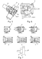
- the exhaust gas line 5 in the region of the valve device 8 is divided into a first exhaust gas channel 12, a second exhaust gas channel 13 and an exhaust gas recirculation channel 14, the exhaust gas recirculation channel 14 communicating with the exhaust gas recirculation line 7.
- the valve device 8 is formed depending on the position for at least partially closing the second exhaust passage 13 or the exhaust gas recirculation passage 14, whereas the first exhaust passage 12 is closed in any position, so that always at least a small exhaust gas flow is discharged via the first exhaust passage 12 to the outside.
- valve device 8 which in this case has an adjustable valve piston 15 which is adjustable to control the exhaust gas recirculation rate in the axial direction.
- This valve piston 15 can For example, be formed of ceramic and thereby have a comparatively smooth surface, which at least makes it difficult, preferably prevented, adhesion of undesirable deposits. Such a smooth valve piston 15 also has a not to be underestimated cleaning effect, since it is stripped off when moving back and forth on its lateral surface.
- the valve piston 15 is between at least three positions (see FIGS. 4a-c ) adjustable, namely one according to the Fig.
- valve piston 15 closes the exhaust gas recirculation passage 14, whereas the first and second exhaust passage 12,13 are fully open, so that in this case no exhaust gas recirculation takes place.
- positions are of course also intermediate positions for particularly fine control / regulation of the exhaust gas recirculation rate conceivable, so that the valve piston 15, for example, only partially protrudes into the exhaust gas recirculation passage 14 and thereby not completely, but only partially closes.
- the Fig. 4b shows the second position of the valve piston 15, in which this example. Without energization of a corresponding actuator 16, for example. An electric motor is located.
- the valve piston 15 is mounted via a bearing 17 and is adjusted by means of a piston rod 18.
- the bearing 17 is here via a corresponding seal 19 against the exhaust-carrying part of the valve device 8 sealed.
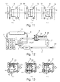
- valve device 8 in the embodiments shown there has a rotatable valve element 20 in the manner of a valve cylinder 21, which may also be of course made of metal or ceramic. Also in this case, the formation of the ceramic valve element 20 has the great advantage of a smooth surface and thereby a reduced tendency for unwanted deposits. As in the valve device 8 according to the Fig. 2 to 4 , the valve element 20 is formed despite the influence of a mass flow in the second exhaust passage 13 and in the exhaust gas recirculation passage 14.
- FIGS. 7a to 7c the three extreme positions of the valve device 8 are shown, wherein in the according to the Fig. 7c shown first position, the valve element 20 closes the second exhaust passage 13, whereas the first exhaust passage 12 and the exhaust gas recirculation passage 14 are fully opened. In accordance with the Fig. 7b In contrast, the valve element 20 opens all the channels 12, 13 and 14 completely. In accordance with the Fig. 7a on the other hand, the rotatable valve element 20 closes the exhaust gas recirculation passage 14, whereas the first and the second exhaust passage 12, 13 are completely open, so that no exhaust gas recirculation takes place in this case. According to the Fig. 7b takes place in comparison to Fig.
- valve device 8 according to the Fig. 2 to 4 are also in the valve device 8 according to the Fig. 5 to 7 most different intermediate positions of the rotatable valve member 20 conceivable, so that in addition to the according to the Fig. 7a to 7c shown extreme positions and any intermediate positions for the exact dosage of the exhaust gas recirculation rate can be displayed.
- the first exhaust passage 12 has a larger cross-section than, for example, the second exhaust passage 13 or the exhaust gas recirculation passage 14.
- the valve element 20 may be formed, as for example, according to the Fig. 7d is shown, so that, for example, a diameter of the valve cylinder 20 formed as a valve member 20 in the region of the second exhaust passage 13 is significantly larger than in the region of the exhaust gas recirculation passage 14th
- valve element 20 is designed as a flap 22.
- extreme position which also represents the first position, closes the valve element 20, that is, the flap 22, the second exhaust passage 13, whereas the first exhaust passage 12 and the exhaust gas recirculation passage 14 are opened.
- Fig. 10b shown position, however, all channels 12,13 and 14 are open.
- Fig. 10a illustrated third position closes the valve element 20, that is, the flap 22, the exhaust gas recirculation passage 14 completely, while the first and second exhaust passage 12,13 are open. In this case, therefore again no exhaust gas recirculation takes place.
- valve device 8 which in this case has an adjustable valve piston 15 with different radii, which is adjustable for controlling the exhaust gas recirculation rate in the axial direction.
- This valve piston 15 may be formed, for example, of ceramic and thus have a comparatively smooth surface, the adhesion of unwanted deposits at least difficult, preferably prevented.
- the valve piston 15 is between at least three positions (see Figures 11a-c ) adjustable, namely one according to the Fig. 11c shown first position in which it closes the second exhaust passage 13, whereas the first exhaust passage 12 and the exhaust gas recirculation passage 14 are fully opened.
- positions are of course also intermediate positions for particularly fine control / regulation of the exhaust gas recirculation rate conceivable, so that the valve piston 15, for example, only partially protrudes into the exhaust gas recirculation passage 14 and thereby not completely, but only partially closes.
- the first exhaust passage 12 is in accordance with the Fig. 11a-c drawn with a broken line, which means that this is purely optional provided. In this case, only the second exhaust passage 13 and the exhaust gas recirculation passage 14 would be present, both of which would be completely closed by the valve piston 15.
- the second exhaust passage 13 has a significantly larger cross-section than the exhaust gas recirculation passage 14, so that the valve piston 15 in this area has a significantly larger diameter than in the region of the exhaust gas recirculation passage.
- the valve device 8 shown can of course be arranged in the confluence of the exhaust gas recirculation line 7 in the intake manifold 6, in which case then in the first and second exhaust pipe 12,13 no exhaust gas, but fresh air would flow out of the intake manifold 6.
- valve device 8 is in FIGS. 12 and 13 shown.
- Fig. 13a to 13c is a valve device 8 in the region of the junction of the exhaust gas recirculation line 7 shown in the intake manifold 6, which in turn has an adjustable valve piston 15 which is adjustable for controlling the exhaust gas recirculation rate in the axial direction.
- the valve piston 15 is between at least three positions (see FIGS. 13a-c ) adjustable, namely one according to the Fig. 13c shown first position in which it closes a second fresh air duct 23, whereas the first fresh air duct 24 and the exhaust gas recirculation passage 14 are fully open. In this position, a comparatively high exhaust gas recirculation rate takes place.
- valve piston 15 opens both the first and second fresh air duct 24,23 and the exhaust gas recirculation passage 14, so that in this position, an exhaust gas recirculation takes place, the exhaust gas recirculation rate, however, is below that of the first position.
- Fig. 13a a third position is shown, in which the valve piston 15 closes the exhaust gas recirculation passage 14, whereas the first and second fresh air passage 24,23 are fully open, so that in this case no exhaust gas recirculation takes place.
- interim positions for the particularly fine control / regulation of the exhaust gas recirculation rate are, of course, also conceivable.
- valve device 8 In the arrangement of the valve device 8 in the region of the confluence of the exhaust gas recirculation line 7 in the intake manifold 6, this receives a new function, ie the valve device 8 controls and not only controls the Exhaust gas recirculation mass flow, but also the intake pressure in the intake manifold 6 in a provision of a throttle valve 25,25 'in the intake manifold 6 and / or in the exhaust line 5 can be additionally influenced on the traceable exhaust gas amount. With the valve device 8 according to the invention, however, such throttle valves can generally be dispensed with.
- valve device 8 With the most diverse embodiments of the valve device 8 according to the invention a particularly precise control / regulation of the exhaust gas recirculation rate in the low pressure region, ie downstream of the turbine 3 of the exhaust gas turbocharger 2 is possible, which was not possible with previous arranged in the exhaust system 5 throttle. At the same time a temperature control is possible. All of the embodiments of the valve device 8 shown have a small space requirement, which also represents a great advantage.
- the valve devices 8 according to the FIGS. 2 to 7 In addition, they generate a small pressure loss, since with the second exhaust gas channel 13 open or the exhaust gas recirculation channel 14 open, the respective valve element 20, 21, 22 or the valve piston 15 does not project into a flow cross-section.
- the ceramic version also reduces unwanted deposits due to the extremely smooth surface.
Landscapes
- Engineering & Computer Science (AREA)
- Chemical & Material Sciences (AREA)
- Combustion & Propulsion (AREA)
- Mechanical Engineering (AREA)
- General Engineering & Computer Science (AREA)
- Exhaust-Gas Circulating Devices (AREA)
- Output Control And Ontrol Of Special Type Engine (AREA)
- Supercharger (AREA)
Claims (4)
- Moteur à combustion interne suralimenté (1) avec un turbocompresseur à gaz d'échappement (2), qui est intégré côté turbine à une voie de gaz d'échappement (5) et côté compresseur à une voie d'aspiration (6) et dans lequel il est prévu une conduite de renvoi de gaz d'échappement (7) reliant la voie de gaz d'échappement (5) et la voie d'aspiration (6), dans lequel la conduite de renvoi de gaz d'échappement (7) dérive, en aval de la turbine (3) du turbocompresseur à gaz d'échappement (2), de la voie de gaz d'échappement (5) et débouche, en amont du compresseur (4), dans la voie d'aspiration (6), dans lequel on aménage dans la zone de la conduite de renvoi de gaz d'échappement (7) un dispositif à soupape (8) pour commander/réguler un débit de renvoi de gaz d'échappement,
caractérisé en ce que :- le dispositif à soupape (8) présente un piston de soupape réglable (15), qui peut se déplacer dans la direction axiale pour commander/réguler le débit de renvoi de gaz d'échappement,- la voie de gaz d'échappement (5) se divise, dans la zone du dispositif à soupape (8), en un premier canal de gaz d'échappement (12), un second canal de gaz d'échappement (13) ainsi qu'un canal de renvoi de gaz d'échappement (14), le dispositif à soupape (8) étant conçu pour fermer le second canal d'échappement (13) ou le canal de renvoi de gaz d'échappement (14),- le piston de soupape (15) peut se déplacer au moins entre trois positions, à savoir :- une première position, dans laquelle il ferme le second canal de gaz d'échappement (13), tandis que le premier canal de gaz d'échappement (12) et le canal de renvoi de gaz d'échappement (14) sont complètement ouverts,- une deuxième position dans laquelle il ouvre complètement le premier et le second canal de gaz d'échappement (12, 13) et le canal de renvoi de gaz d'échappement (14), et- une troisième position dans laquelle il ferme le canal de renvoi de gaz d'échappement (14), tandis que le premier et le second canal de gaz d'échappement (12, 13) sont complètement ouverts. - Moteur à combustion interne selon la revendication 1,
caractérisé en ce que :- entre la turbine (3) du turbocompresseur à gaz d'échappement (2) et le dispositif à soupape (8) est aménagé un filtre (9), en particulier un filtre à particules Diesel et/ou- entre le compresseur (4) et le moteur à combustion interne (1) est aménagé un refroidisseur d'air de suralimentation (10) et/ou- entre le dispositif à soupape (8) et la voie de gaz d'échappement (5) est aménagé un refroidisseur de gaz d'échappement (11). - Moteur à combustion interne selon la revendication 2,
caractérisé en ce que :- le dispositif à soupape (8) est aménagé dans la zone de la dérivation de la conduite de renvoi de gaz d'échappement (7) vis-à-vis de la voie de gaz d'échappement (5) ou- le dispositif à soupape (8) est aménagé dans la zone de l'embouchure de la conduite de renvoi de gaz d'échappement (7) dans la voie d'aspiration (6) ou- le dispositif à soupape (8) est aménagé dans la zone du filtre (9), en particulier dans celui-ci, ou- le dispositif à soupape (8) est aménagé dans la zone du refroidisseur d'air de suralimentation (10). - Moteur à combustion interne selon l'une quelconque des revendications 1 à 3,
caractérisé en ce que :le piston de soupape (15) est formé de céramique.
Applications Claiming Priority (3)
| Application Number | Priority Date | Filing Date | Title |
|---|---|---|---|
| DE102011080101 | 2011-07-29 | ||
| DE102011080965A DE102011080965A1 (de) | 2011-07-29 | 2011-08-15 | Aufgeladene Brennkraftmaschine |
| PCT/EP2012/064703 WO2013017524A1 (fr) | 2011-07-29 | 2012-07-26 | Moteur à combustion interne suralimenté |
Publications (2)
| Publication Number | Publication Date |
|---|---|
| EP2737195A1 EP2737195A1 (fr) | 2014-06-04 |
| EP2737195B1 true EP2737195B1 (fr) | 2015-09-16 |
Family
ID=47502940
Family Applications (1)
| Application Number | Title | Priority Date | Filing Date |
|---|---|---|---|
| EP12745438.7A Not-in-force EP2737195B1 (fr) | 2011-07-29 | 2012-07-26 | Moteur à combustion interne suralimenté |
Country Status (6)
| Country | Link |
|---|---|
| US (1) | US9371772B2 (fr) |
| EP (1) | EP2737195B1 (fr) |
| JP (1) | JP5905093B2 (fr) |
| CN (1) | CN103748348B (fr) |
| DE (1) | DE102011080965A1 (fr) |
| WO (1) | WO2013017524A1 (fr) |
Families Citing this family (2)
| Publication number | Priority date | Publication date | Assignee | Title |
|---|---|---|---|---|
| CN104806345B (zh) * | 2015-04-10 | 2017-08-04 | 中国第一汽车股份有限公司无锡油泵油嘴研究所 | 一种发动机电动气体配给装置 |
| KR101664069B1 (ko) * | 2015-05-07 | 2016-10-10 | 현대자동차 주식회사 | 저압 이지알 시스템을 갖는 엔진 및 이의 제어방법 |
Family Cites Families (17)
| Publication number | Priority date | Publication date | Assignee | Title |
|---|---|---|---|---|
| DE3272895D1 (en) * | 1981-09-22 | 1986-10-02 | Bbc Brown Boveri & Cie | Supercharging process for internal-combustion engines by a turbocharger with variable exhaust swallow capacity, and internal-combustion engine working according to this process |
| JPH06108923A (ja) * | 1992-09-25 | 1994-04-19 | Isuzu Motors Ltd | 排気還流制御装置 |
| US5822958A (en) * | 1997-06-02 | 1998-10-20 | Winpak Lane, Inc. | Sanitary fill tube and piston valve assembly for a pouch packaging machine |
| US6006732A (en) * | 1998-09-03 | 1999-12-28 | Navistar International Transportation Corp | Balanced flow EGR control apparatus |
| US6220233B1 (en) * | 1999-10-13 | 2001-04-24 | Caterpillar Inc. | Exhaust gas recirculation system having variable valve timing and method of using same in an internal combustion engine |
| US6422217B1 (en) * | 2000-12-19 | 2002-07-23 | Caterpillar Inc. | Back pressure valve drive EGR system |
| DE10222917B4 (de) * | 2002-05-24 | 2007-12-20 | Man Nutzfahrzeuge Ag | Aufgeladene Brennkraftmaschine |
| JP2008530423A (ja) * | 2005-02-07 | 2008-08-07 | ボーグワーナー・インコーポレーテッド | ディーゼルエンジン用の排気スロットルegr弁モジュール |
| JP4396581B2 (ja) * | 2005-06-02 | 2010-01-13 | 株式会社デンソー | 内燃機関のegr制御装置 |
| WO2008024609A1 (fr) * | 2006-08-04 | 2008-02-28 | Borgwarner Inc. | Soupape multifonction pour utilisation dans un système de pompage des gaz d'échappement |
| DE102008005400A1 (de) | 2007-01-19 | 2008-07-24 | Behr Thermot-Tronik Gmbh | Wärmeübertragerventileinrichtung |
| DE102007048297A1 (de) | 2007-10-08 | 2009-04-09 | Behr Gmbh & Co. Kg | Ventilvorrichtung zur Regelung eines rückgeführten gasförmigen Fluids, Wärmetauscher, Verfahren zur Regelung einer Ventilvorrichtung und/oder zur Regelung eines Wärmetauschers |
| DE102008048912B4 (de) * | 2008-09-26 | 2021-11-04 | Faurecia Emissions Control Technologies, Germany Gmbh | Abgasanlage und Abgasventil zur Steuerung eines Volumenstroms von Abgas sowie ein Verfahren zur Steuerung eines Volumenstroms |
| IT1396027B1 (it) * | 2009-10-19 | 2012-11-09 | Dellorto Spa | Valvola egr per applicazioni di tipo low pressure, nella tecnica del ricircolo controllato di gas combusti in motori a combustione interna. |
| US7987837B2 (en) * | 2010-02-16 | 2011-08-02 | Ford Global Technologies, Llc | Exhaust treatment system for internal combustion engine |
| CN102822577B (zh) * | 2010-04-14 | 2014-11-19 | 博格华纳公司 | 多功能阀 |
| DE102011016630A1 (de) * | 2011-04-09 | 2012-10-11 | Volkswagen Aktiengesellschaft | Stellvorrichtung und Abgasstrang |
-
2011
- 2011-08-15 DE DE102011080965A patent/DE102011080965A1/de not_active Withdrawn
-
2012
- 2012-07-26 WO PCT/EP2012/064703 patent/WO2013017524A1/fr active Application Filing
- 2012-07-26 CN CN201280034202.7A patent/CN103748348B/zh not_active Expired - Fee Related
- 2012-07-26 US US14/235,791 patent/US9371772B2/en not_active Expired - Fee Related
- 2012-07-26 JP JP2014523292A patent/JP5905093B2/ja active Active
- 2012-07-26 EP EP12745438.7A patent/EP2737195B1/fr not_active Not-in-force
Also Published As
| Publication number | Publication date |
|---|---|
| DE102011080965A1 (de) | 2013-01-31 |
| JP5905093B2 (ja) | 2016-04-20 |
| CN103748348A (zh) | 2014-04-23 |
| JP2014521871A (ja) | 2014-08-28 |
| WO2013017524A1 (fr) | 2013-02-07 |
| CN103748348B (zh) | 2016-04-27 |
| US9371772B2 (en) | 2016-06-21 |
| US20140283796A1 (en) | 2014-09-25 |
| EP2737195A1 (fr) | 2014-06-04 |
Similar Documents
| Publication | Publication Date | Title |
|---|---|---|
| EP1763627B1 (fr) | Moteur thermique dote d'une epuration des gaz d'echappement et procede pour le faire fonctionner | |
| EP2503126B1 (fr) | Moteur à combustion interne équipé de deux turbines à décharge et procédé de fonctionnement d'un tel moteur à combustion interne | |
| EP2108807B1 (fr) | Dispositif de recirculation des gaz d'échappement pour un moteur à combustion interne | |
| AT512567B1 (de) | Funktionsmodul mit einem Abgasturbolader und einem Abgaskrümmer | |
| EP2267291A2 (fr) | Moteur à piston et méthode d'opération | |
| EP2134943A1 (fr) | Moteur à combustion interne suralimenté et procédé | |
| DE102007060415A1 (de) | Brennkraftmaschine und Verfahren zum Steuern einer Brennkraftmaschine für ein Kraftfahrzeug | |
| EP1455078B1 (fr) | Moteur à combustion interne ayant un turbocompresseur et un système de recyclage des gaz d'échappement | |
| DE102009004418A1 (de) | Verfahren zur Nachbehandlung eines Abgasstroms einer mehrzylindrigen Brennkraftmaschine eines Fahrzeuges sowie Abgasnachbehandlungsvorrichtung | |
| DE202017105126U1 (de) | Abgasleitsystem | |
| DE102008048681A1 (de) | Brennkraftmaschine mit zwei Ladern und Verfahren zum Betreiben derselben | |
| DE102009004417A1 (de) | Verfahren zur Nachbehandlung eines Abgasstroms einer mehrzylindrigen Brennkraftmaschine eines Fahrzeuges sowie Abgasnachbehandlungsvorrichtung | |
| DE102008056337A1 (de) | Brennkraftmaschine mit Abgasrückführung | |
| WO2006111280A1 (fr) | Moteur thermique a recyclage des gaz d'echappement | |
| DE102009006013A1 (de) | Abgasklappenvorrichtung und Abgaswärmerückgewinnungssystem einer Verbrennungskraftmaschine | |
| DE112007000298B4 (de) | Auspuffelement für Anlage zum Ausströmen von Gasen | |
| DE102017119537B4 (de) | Abgasleitsystem | |
| EP2737195B1 (fr) | Moteur à combustion interne suralimenté | |
| WO2010128040A1 (fr) | Moteur à combustion interne et procédé de fonctionnement associé | |
| DE102007025437A1 (de) | Verfahren für eine Brennkraftmaschine mit einem Abgasturbolader | |
| DE102010045503A1 (de) | Vorrichtung zur Abgasrückführung an einer Brennkraftmaschine | |
| DE102015200045A1 (de) | Verfahren zum optimierten Betreiben einer Brennkraftmaschine und Brennkraftmaschine zur Durchführung eines derartigen Verfahrens | |
| DE102016015357A1 (de) | Drosseleinrichtung für einen Abgastrakt einer Verbrennungskraftmaschine | |
| DE102011120168A1 (de) | Verdichter für einen Abgasturbolader | |
| DE102013020448A1 (de) | Verfahren zum Betreiben eines Kraftwagens |
Legal Events
| Date | Code | Title | Description |
|---|---|---|---|
| PUAI | Public reference made under article 153(3) epc to a published international application that has entered the european phase |
Free format text: ORIGINAL CODE: 0009012 |
|
| 17P | Request for examination filed |
Effective date: 20140123 |
|
| AK | Designated contracting states |
Kind code of ref document: A1 Designated state(s): AL AT BE BG CH CY CZ DE DK EE ES FI FR GB GR HR HU IE IS IT LI LT LU LV MC MK MT NL NO PL PT RO RS SE SI SK SM TR |
|
| DAX | Request for extension of the european patent (deleted) | ||
| GRAP | Despatch of communication of intention to grant a patent |
Free format text: ORIGINAL CODE: EPIDOSNIGR1 |
|
| INTG | Intention to grant announced |
Effective date: 20150323 |
|
| GRAS | Grant fee paid |
Free format text: ORIGINAL CODE: EPIDOSNIGR3 |
|
| GRAA | (expected) grant |
Free format text: ORIGINAL CODE: 0009210 |
|
| AK | Designated contracting states |
Kind code of ref document: B1 Designated state(s): AL AT BE BG CH CY CZ DE DK EE ES FI FR GB GR HR HU IE IS IT LI LT LU LV MC MK MT NL NO PL PT RO RS SE SI SK SM TR |
|
| REG | Reference to a national code |
Ref country code: GB Ref legal event code: FG4D Free format text: NOT ENGLISH |
|
| REG | Reference to a national code |
Ref country code: CH Ref legal event code: EP |
|
| REG | Reference to a national code |
Ref country code: IE Ref legal event code: FG4D Free format text: LANGUAGE OF EP DOCUMENT: GERMAN |
|
| REG | Reference to a national code |
Ref country code: AT Ref legal event code: REF Ref document number: 750023 Country of ref document: AT Kind code of ref document: T Effective date: 20151015 |
|
| REG | Reference to a national code |
Ref country code: DE Ref legal event code: R096 Ref document number: 502012004597 Country of ref document: DE |
|
| REG | Reference to a national code |
Ref country code: NL Ref legal event code: MP Effective date: 20150916 |
|
| PG25 | Lapsed in a contracting state [announced via postgrant information from national office to epo] |
Ref country code: FI Free format text: LAPSE BECAUSE OF FAILURE TO SUBMIT A TRANSLATION OF THE DESCRIPTION OR TO PAY THE FEE WITHIN THE PRESCRIBED TIME-LIMIT Effective date: 20150916 Ref country code: GR Free format text: LAPSE BECAUSE OF FAILURE TO SUBMIT A TRANSLATION OF THE DESCRIPTION OR TO PAY THE FEE WITHIN THE PRESCRIBED TIME-LIMIT Effective date: 20151217 Ref country code: NO Free format text: LAPSE BECAUSE OF FAILURE TO SUBMIT A TRANSLATION OF THE DESCRIPTION OR TO PAY THE FEE WITHIN THE PRESCRIBED TIME-LIMIT Effective date: 20151216 Ref country code: LT Free format text: LAPSE BECAUSE OF FAILURE TO SUBMIT A TRANSLATION OF THE DESCRIPTION OR TO PAY THE FEE WITHIN THE PRESCRIBED TIME-LIMIT Effective date: 20150916 Ref country code: LV Free format text: LAPSE BECAUSE OF FAILURE TO SUBMIT A TRANSLATION OF THE DESCRIPTION OR TO PAY THE FEE WITHIN THE PRESCRIBED TIME-LIMIT Effective date: 20150916 |
|
| REG | Reference to a national code |
Ref country code: LT Ref legal event code: MG4D |
|
| PG25 | Lapsed in a contracting state [announced via postgrant information from national office to epo] |
Ref country code: SE Free format text: LAPSE BECAUSE OF FAILURE TO SUBMIT A TRANSLATION OF THE DESCRIPTION OR TO PAY THE FEE WITHIN THE PRESCRIBED TIME-LIMIT Effective date: 20150916 Ref country code: HR Free format text: LAPSE BECAUSE OF FAILURE TO SUBMIT A TRANSLATION OF THE DESCRIPTION OR TO PAY THE FEE WITHIN THE PRESCRIBED TIME-LIMIT Effective date: 20150916 Ref country code: RS Free format text: LAPSE BECAUSE OF FAILURE TO SUBMIT A TRANSLATION OF THE DESCRIPTION OR TO PAY THE FEE WITHIN THE PRESCRIBED TIME-LIMIT Effective date: 20150916 |
|
| PG25 | Lapsed in a contracting state [announced via postgrant information from national office to epo] |
Ref country code: NL Free format text: LAPSE BECAUSE OF FAILURE TO SUBMIT A TRANSLATION OF THE DESCRIPTION OR TO PAY THE FEE WITHIN THE PRESCRIBED TIME-LIMIT Effective date: 20150916 |
|
| PG25 | Lapsed in a contracting state [announced via postgrant information from national office to epo] |
Ref country code: IS Free format text: LAPSE BECAUSE OF FAILURE TO SUBMIT A TRANSLATION OF THE DESCRIPTION OR TO PAY THE FEE WITHIN THE PRESCRIBED TIME-LIMIT Effective date: 20160116 Ref country code: IT Free format text: LAPSE BECAUSE OF FAILURE TO SUBMIT A TRANSLATION OF THE DESCRIPTION OR TO PAY THE FEE WITHIN THE PRESCRIBED TIME-LIMIT Effective date: 20150916 Ref country code: CZ Free format text: LAPSE BECAUSE OF FAILURE TO SUBMIT A TRANSLATION OF THE DESCRIPTION OR TO PAY THE FEE WITHIN THE PRESCRIBED TIME-LIMIT Effective date: 20150916 Ref country code: ES Free format text: LAPSE BECAUSE OF FAILURE TO SUBMIT A TRANSLATION OF THE DESCRIPTION OR TO PAY THE FEE WITHIN THE PRESCRIBED TIME-LIMIT Effective date: 20150916 Ref country code: EE Free format text: LAPSE BECAUSE OF FAILURE TO SUBMIT A TRANSLATION OF THE DESCRIPTION OR TO PAY THE FEE WITHIN THE PRESCRIBED TIME-LIMIT Effective date: 20150916 Ref country code: SK Free format text: LAPSE BECAUSE OF FAILURE TO SUBMIT A TRANSLATION OF THE DESCRIPTION OR TO PAY THE FEE WITHIN THE PRESCRIBED TIME-LIMIT Effective date: 20150916 |
|
| PG25 | Lapsed in a contracting state [announced via postgrant information from national office to epo] |
Ref country code: PT Free format text: LAPSE BECAUSE OF FAILURE TO SUBMIT A TRANSLATION OF THE DESCRIPTION OR TO PAY THE FEE WITHIN THE PRESCRIBED TIME-LIMIT Effective date: 20160118 Ref country code: RO Free format text: LAPSE BECAUSE OF FAILURE TO SUBMIT A TRANSLATION OF THE DESCRIPTION OR TO PAY THE FEE WITHIN THE PRESCRIBED TIME-LIMIT Effective date: 20150916 Ref country code: PL Free format text: LAPSE BECAUSE OF FAILURE TO SUBMIT A TRANSLATION OF THE DESCRIPTION OR TO PAY THE FEE WITHIN THE PRESCRIBED TIME-LIMIT Effective date: 20150916 |
|
| REG | Reference to a national code |
Ref country code: DE Ref legal event code: R097 Ref document number: 502012004597 Country of ref document: DE |
|
| PLBE | No opposition filed within time limit |
Free format text: ORIGINAL CODE: 0009261 |
|
| STAA | Information on the status of an ep patent application or granted ep patent |
Free format text: STATUS: NO OPPOSITION FILED WITHIN TIME LIMIT |
|
| REG | Reference to a national code |
Ref country code: FR Ref legal event code: PLFP Year of fee payment: 5 |
|
| 26N | No opposition filed |
Effective date: 20160617 |
|
| PG25 | Lapsed in a contracting state [announced via postgrant information from national office to epo] |
Ref country code: DK Free format text: LAPSE BECAUSE OF FAILURE TO SUBMIT A TRANSLATION OF THE DESCRIPTION OR TO PAY THE FEE WITHIN THE PRESCRIBED TIME-LIMIT Effective date: 20150916 |
|
| PG25 | Lapsed in a contracting state [announced via postgrant information from national office to epo] |
Ref country code: SI Free format text: LAPSE BECAUSE OF FAILURE TO SUBMIT A TRANSLATION OF THE DESCRIPTION OR TO PAY THE FEE WITHIN THE PRESCRIBED TIME-LIMIT Effective date: 20150916 |
|
| PG25 | Lapsed in a contracting state [announced via postgrant information from national office to epo] |
Ref country code: BE Free format text: LAPSE BECAUSE OF NON-PAYMENT OF DUE FEES Effective date: 20160731 |
|
| REG | Reference to a national code |
Ref country code: CH Ref legal event code: PL |
|
| PG25 | Lapsed in a contracting state [announced via postgrant information from national office to epo] |
Ref country code: MC Free format text: LAPSE BECAUSE OF FAILURE TO SUBMIT A TRANSLATION OF THE DESCRIPTION OR TO PAY THE FEE WITHIN THE PRESCRIBED TIME-LIMIT Effective date: 20150916 |
|
| PG25 | Lapsed in a contracting state [announced via postgrant information from national office to epo] |
Ref country code: LI Free format text: LAPSE BECAUSE OF NON-PAYMENT OF DUE FEES Effective date: 20160731 Ref country code: CH Free format text: LAPSE BECAUSE OF NON-PAYMENT OF DUE FEES Effective date: 20160731 |
|
| REG | Reference to a national code |
Ref country code: IE Ref legal event code: MM4A |
|
| REG | Reference to a national code |
Ref country code: FR Ref legal event code: PLFP Year of fee payment: 6 |
|
| PG25 | Lapsed in a contracting state [announced via postgrant information from national office to epo] |
Ref country code: IE Free format text: LAPSE BECAUSE OF NON-PAYMENT OF DUE FEES Effective date: 20160726 |
|
| PG25 | Lapsed in a contracting state [announced via postgrant information from national office to epo] |
Ref country code: LU Free format text: LAPSE BECAUSE OF NON-PAYMENT OF DUE FEES Effective date: 20160726 |
|
| PG25 | Lapsed in a contracting state [announced via postgrant information from national office to epo] |
Ref country code: HU Free format text: LAPSE BECAUSE OF FAILURE TO SUBMIT A TRANSLATION OF THE DESCRIPTION OR TO PAY THE FEE WITHIN THE PRESCRIBED TIME-LIMIT; INVALID AB INITIO Effective date: 20120726 Ref country code: SM Free format text: LAPSE BECAUSE OF FAILURE TO SUBMIT A TRANSLATION OF THE DESCRIPTION OR TO PAY THE FEE WITHIN THE PRESCRIBED TIME-LIMIT Effective date: 20150916 Ref country code: CY Free format text: LAPSE BECAUSE OF FAILURE TO SUBMIT A TRANSLATION OF THE DESCRIPTION OR TO PAY THE FEE WITHIN THE PRESCRIBED TIME-LIMIT Effective date: 20150916 |
|
| PG25 | Lapsed in a contracting state [announced via postgrant information from national office to epo] |
Ref country code: MT Free format text: LAPSE BECAUSE OF FAILURE TO SUBMIT A TRANSLATION OF THE DESCRIPTION OR TO PAY THE FEE WITHIN THE PRESCRIBED TIME-LIMIT Effective date: 20150916 Ref country code: MK Free format text: LAPSE BECAUSE OF FAILURE TO SUBMIT A TRANSLATION OF THE DESCRIPTION OR TO PAY THE FEE WITHIN THE PRESCRIBED TIME-LIMIT Effective date: 20150916 |
|
| REG | Reference to a national code |
Ref country code: FR Ref legal event code: PLFP Year of fee payment: 7 |
|
| PG25 | Lapsed in a contracting state [announced via postgrant information from national office to epo] |
Ref country code: BG Free format text: LAPSE BECAUSE OF FAILURE TO SUBMIT A TRANSLATION OF THE DESCRIPTION OR TO PAY THE FEE WITHIN THE PRESCRIBED TIME-LIMIT Effective date: 20150916 |
|
| PG25 | Lapsed in a contracting state [announced via postgrant information from national office to epo] |
Ref country code: TR Free format text: LAPSE BECAUSE OF FAILURE TO SUBMIT A TRANSLATION OF THE DESCRIPTION OR TO PAY THE FEE WITHIN THE PRESCRIBED TIME-LIMIT Effective date: 20150916 Ref country code: AL Free format text: LAPSE BECAUSE OF FAILURE TO SUBMIT A TRANSLATION OF THE DESCRIPTION OR TO PAY THE FEE WITHIN THE PRESCRIBED TIME-LIMIT Effective date: 20150916 |
|
| PGFP | Annual fee paid to national office [announced via postgrant information from national office to epo] |
Ref country code: FR Payment date: 20180726 Year of fee payment: 7 |
|
| PGFP | Annual fee paid to national office [announced via postgrant information from national office to epo] |
Ref country code: AT Payment date: 20180727 Year of fee payment: 7 Ref country code: GB Payment date: 20180731 Year of fee payment: 7 |
|
| PGFP | Annual fee paid to national office [announced via postgrant information from national office to epo] |
Ref country code: DE Payment date: 20180928 Year of fee payment: 7 |
|
| REG | Reference to a national code |
Ref country code: DE Ref legal event code: R119 Ref document number: 502012004597 Country of ref document: DE |
|
| REG | Reference to a national code |
Ref country code: AT Ref legal event code: MM01 Ref document number: 750023 Country of ref document: AT Kind code of ref document: T Effective date: 20190726 |
|
| GBPC | Gb: european patent ceased through non-payment of renewal fee |
Effective date: 20190726 |
|
| PG25 | Lapsed in a contracting state [announced via postgrant information from national office to epo] |
Ref country code: GB Free format text: LAPSE BECAUSE OF NON-PAYMENT OF DUE FEES Effective date: 20190726 Ref country code: DE Free format text: LAPSE BECAUSE OF NON-PAYMENT OF DUE FEES Effective date: 20200201 Ref country code: AT Free format text: LAPSE BECAUSE OF NON-PAYMENT OF DUE FEES Effective date: 20190726 |
|
| PG25 | Lapsed in a contracting state [announced via postgrant information from national office to epo] |
Ref country code: FR Free format text: LAPSE BECAUSE OF NON-PAYMENT OF DUE FEES Effective date: 20190731 |