EP2050918A2 - Absenkdichtung mit Durchgangsöffnung - Google Patents
Absenkdichtung mit Durchgangsöffnung Download PDFInfo
- Publication number
- EP2050918A2 EP2050918A2 EP08405257A EP08405257A EP2050918A2 EP 2050918 A2 EP2050918 A2 EP 2050918A2 EP 08405257 A EP08405257 A EP 08405257A EP 08405257 A EP08405257 A EP 08405257A EP 2050918 A2 EP2050918 A2 EP 2050918A2
- Authority
- EP
- European Patent Office
- Prior art keywords
- door seal
- shortenable
- lowering mechanism
- seal according
- sealing strip
- Prior art date
- Legal status (The legal status is an assumption and is not a legal conclusion. Google has not performed a legal analysis and makes no representation as to the accuracy of the status listed.)
- Granted
Links
- 238000007789 sealing Methods 0.000 claims abstract description 42
- 230000007246 mechanism Effects 0.000 claims abstract description 37
- 230000006378 damage Effects 0.000 claims 1
- 230000005540 biological transmission Effects 0.000 description 4
- 238000004904 shortening Methods 0.000 description 4
- 210000002414 leg Anatomy 0.000 description 3
- 229910052751 metal Inorganic materials 0.000 description 2
- 239000002184 metal Substances 0.000 description 2
- 230000006978 adaptation Effects 0.000 description 1
- 229910052782 aluminium Inorganic materials 0.000 description 1
- XAGFODPZIPBFFR-UHFFFAOYSA-N aluminium Chemical compound [Al] XAGFODPZIPBFFR-UHFFFAOYSA-N 0.000 description 1
- 230000001419 dependent effect Effects 0.000 description 1
- 239000013536 elastomeric material Substances 0.000 description 1
- 238000009413 insulation Methods 0.000 description 1
- 239000000463 material Substances 0.000 description 1
- 230000003287 optical effect Effects 0.000 description 1
- 229920001296 polysiloxane Polymers 0.000 description 1
- 230000001960 triggered effect Effects 0.000 description 1
- 210000000689 upper leg Anatomy 0.000 description 1
Images

Classifications
-
- E—FIXED CONSTRUCTIONS
- E06—DOORS, WINDOWS, SHUTTERS, OR ROLLER BLINDS IN GENERAL; LADDERS
- E06B—FIXED OR MOVABLE CLOSURES FOR OPENINGS IN BUILDINGS, VEHICLES, FENCES OR LIKE ENCLOSURES IN GENERAL, e.g. DOORS, WINDOWS, BLINDS, GATES
- E06B7/00—Special arrangements or measures in connection with doors or windows
- E06B7/16—Sealing arrangements on wings or parts co-operating with the wings
- E06B7/18—Sealing arrangements on wings or parts co-operating with the wings by means of movable edgings, e.g. draught sealings additionally used for bolting, e.g. by spring force or with operating lever
- E06B7/20—Sealing arrangements on wings or parts co-operating with the wings by means of movable edgings, e.g. draught sealings additionally used for bolting, e.g. by spring force or with operating lever automatically withdrawn when the wing is opened, e.g. by means of magnetic attraction, a pin or an inclined surface, especially for sills
- E06B7/215—Sealing arrangements on wings or parts co-operating with the wings by means of movable edgings, e.g. draught sealings additionally used for bolting, e.g. by spring force or with operating lever automatically withdrawn when the wing is opened, e.g. by means of magnetic attraction, a pin or an inclined surface, especially for sills with sealing strip being moved to a retracted position by elastic means, e.g. springs
Definitions
- the invention relates to a lowerable door seal with a passage opening for a locking bolt according to the preamble of patent claim 1.
- Out EP 0 338 974 is a lowerable seal for a door without a threshold known. It has an outer guide rail and a sealing strip held therein with carrier rail and sealing lip.
- the carrier profile rail can be raised and lowered via a lowering mechanism with respect to the guide profile rail.
- the guide rail is mounted in a door groove or on a lower end surface of the door, so that the lowered sealing strip rests on the floor and seals a lower gap of the door. It thus protects against draft and unwanted light immissions and also serves as sound insulation.
- a possible lowering mechanism of such a door seal is, for example, in DE 195 16 530 described.
- Two or more leaf springs arranged one behind the other are fastened both to the guide profile rail and to the carrier profile rail.
- An actuating rod which is connected directly or via a power transmission rod with the leaf springs, protrudes on one side at a front end of the seal. If the door is closed, this actuating rod is pressed into the seal, wherein it biases the springs. These push the sealing strip downwards direction Ground. When the door is opened again, the springs relax, the actuating rod is pushed out and the sealing strip is raised again.
- EP 1 191 182 and EP 1 308 590 known to provide such seals with a through hole, which serves to receive a locking bolt of a cant or drive bolt.
- the bolt passes through the guide rail and the sealing strip.
- the inventive door seal has a guide rail and a sealing strip, which is held in the guide rail and can be raised and lowered via a lowering mechanism. Further, it has a through hole for receiving a locking bolt and at least one actuating rod for automatically actuating the lowering mechanism, which projects the guide rail at a first end.
- the passage opening is arranged adjacent to a first end opposite the second end of the door seal.
- the door seal at the first and second end each have a shortenable region over which the guide profile rail and at least one sealing element of the sealing strip completely extend. These shortenable areas neither have the passage opening nor does the lowering mechanism project into these areas.
- the through-opening preferably adjoins the shortenable region of the second end, wherein the through-opening or the passage region of the seal defined by it preferably adjoins directly to this shortenable region.
- the door seal has a core portion which includes the lowering mechanism and which can not be shortened without destroying the lowering mechanism.
- the passage opening or the passage area of the seal defined by it preferably directly adjoins this core area.
- the seal is shortened to the desired length, but the passage opening can also be adapted locally to the position of the locking bolt or to the type of lock.
- the seal is first shortened at the end close to the passage opening, ie the distance of this opening from the rail end is selected. Subsequently, the seal on the opposite End shortened and so the total length of the seal chosen.
- the gasket because it is customizable, can be produced inexpensively. It can be sold as a stock item because customization is now possible.
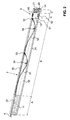
- FIG. 1 shows a door seal according to the invention, as it can be installed in a door groove of a threshold-free door or can be attached to a front edge of the door.
- the door seal has a guide rail 1, which is designed substantially U-shaped and open at the bottom. It has an upper bridge and two thighs up. In the upper area, near the upper web of the guide rail 1, two vertically projecting from the legs, inwardly projecting webs are preferably present on the inner sides of both legs, which preferably extend approximately over the entire length of the rail 1 and which together with the uppermost Bridge a guide groove for a lowering mechanism 3 described later form.
- a sealing strip 2 is arranged, which is preferably designed to be the same length as the guide rail 1. However, it may also be formed longer or shorter.
- the sealing strip 2 has a carrier profile rail 20 and a sealing element 21 arranged thereon.
- the sealing strip 2 can be raised and lowered relative to the guide rail 1. This is effected by a lowering mechanism 3, which at the same time holds or fastens the sealing strip 2 in the guide profile rail 1.
- the sealing element 21 is in the lowered state on the floor below the door, thus protecting against draft, light and sound.
- the carrier rail 20 and the guide rail 1 are preferably made of aluminum.
- the sealing element 21 is preferably made of rubber, silicone or other elastomeric material.
- the sealing element 21 is shown here as a one-piece strip with a U-shaped cross-section, which is fastened on both sides to the carrier profile rail 20 and projects beyond these attachment points with two legs. Other forms of sealing elements, single or multi-piece, but can also be used.
- the seal has in one end region a passage opening 5 for receiving a locking bolt, not shown here, for locking the door.
- the locking bolt is preferably part of a cant or drive bolt.
- the passage opening 5 passes through the entire seal in the vertical direction from top to bottom. Preferably, it is elongated. But it can also be configured round or square.
- the passage opening 5 is essentially formed by aligned holes in the individual parts of the seal. So for example, the guide profile rail 1 has a first through-hole 50, the carrier profile rail 20 has a second through-hole 51, and the sealing element 21 has a third through-hole 52. These holes can be arranged centrally or laterally offset with respect to the longitudinal axis of the seal. Depending on the design of the carrier rail 20, there is no need for a through hole.
- the individual holes may be round or preferably oblong, in particular oval.
- the actuating mechanism or lowering mechanism 3 is in FIG. 2 recognizable. This is preferably a mechanism such as that mentioned in the opening paragraph DE 195 16 530 is described. He is purely mechanically trained and works with spring force, being activated via an operating knob 6, which on one side dominates the guide rail 1. Under operating button 6 is understood here any embodiment which is suitable to mechanically trigger the mechanism when opening or closing the door.
- the mechanism 3 has one or more leaf springs 31, 32, which are arranged one behind the other in the longitudinal direction.
- a connecting rod 35 is connected to the operating knob 6.
- the operating knob 6 may preferably be plugged or clipped, screwed to the rod 35 or otherwise releasably connected. When shortening the seal of the operating knob 6 is removed, the connecting rod 35 is shortened to the desired length and the operating knob 6 screwed or otherwise secured.
- a first spring 31 is fixedly connected at a first end to the connecting rod 35, preferably welded.
- This rod 35 is also coupled to a power transmission rod 30 which is fixedly connected to a first end of the second spring 32. Preferably, they are welded.
- the power transmission rod 30 is slidably held guided in the above-mentioned groove of the guide rail 1.
- the first spring 31 and the second spring 32 are also fastened at their second ends by means of first fastening means 33 on the guide rail 1. In their central region, they are fastened by means of second fastening means 34 to the sealing strip, more precisely to the carrier profile 20.
- the operating knob 6 is thus preferably non-destructively releasably connected to the lowering mechanism 3. This knob 6 is disposed at the end remote from the through hole 5.
- the door projecting actuator button 6 presses when closing the door against the door frame and thus biases the springs 31, 32.
- the sealing strip 2 is thereby lowered automatically.
- the operating knob 6 can emerge again from the rail and the springs 31, 32 are relaxed.
- the sealing strip 2 is raised automatically.
- a locking bolt which passes through the through hole 5, can be operated independently of the position of the sealing strip 2.
- the door seal now has at least four differently formed zones or regions in its longitudinal direction.
- the end zones 11, 14 arranged on both sides can be shortened and the two middle zones 12, 13 can not be shortened or not easily shortened.
- At least a portion of the integrally formed parts, such as support rail 20, guide rail 1 and sealing element 21, are preferably optically divided into these areas.
- the guide rail 1 preferably has an optical subdivision.
- the seal is in its longitudinal direction in a first actuation-side shortenable region 11, a subsequent thereto second region, the core region 12, a third adjacent thereto, the passage area 13 and adjoining the fourth region, the hole-side shortenable region 14 divided.
- the core portion 12 includes the mechanical lowering mechanism 3 and therefore can not be shortened without destroying the mechanism 3.
- the core portion 12 is not formed substantially longer than the mechanism 3.
- the passage portion 13 includes the through hole 5 and is just long enough so that the opening 5 still has a sufficient material border.
- the two shortenable areas 11, 14 are penetrated only by short or removable parts of the seal.
- the first shortenable region 11 is essentially penetrated only by the sealing strip 2 and the actuating rod 6.
- the latter can preferably be removed before shortening this region 11 and then screwed in again. In this case, it can also be shortened separately, for example by being sawed off or by being formed in several pieces and simply removing a corresponding piece, e.g. unscrewed, will.
- the sealing strip 2 can be sawed through easily, either together with the guide rail 1 or separately to this.
- the second hole-side shortenable region 14 is preferably even penetrated only by the sealing strip 2, so that the above applies here as well.
- the two shortenable regions 11, 14 are preferably optically marked as such on the outside of the guide profile rail 1. They can be painted or divided from the remaining areas by a simple painted or indented stroke or a glued strip.
- the second shortenable region 14 By shortening the second shortenable region 14, the distance of the passage opening 5 from the seal end is selected. By the subsequent shortening of the first shortenable region 11, the total length of the seal is adjusted.
- the seal is shortened in the figures and not shown to scale.
- the second region 12 is formed too short compared to the other regions.
- the inventive seal thus allows a simple way of cutting the seal on both sides, so that on the one hand the length of the seal and on the other hand, the position of the through hole over a large area can be selected independently on site or at the door manufacturer.
Abstract
Description
- Die Erfindung betrifft eine absenkbare Türdichtung mit einer Durchgangsöffnung für einen Verriegelungsbolzen gemäss Oberbegriff des Patentanspruchs 1.
- Aus
EP 0 338 974 ist eine absenkbare Dichtung für eine schwellenlose Tür bekannt. Sie weist eine äussere Führungsprofilschiene und eine darin gehaltene Dichtleiste mit Trägerprofilschiene und Dichtlippe auf. Die Trägerprofilschiene lässt sich über einen Absenkmechanismus bezüglich der Führungsprofilschiene anheben und absenken. Die Führungsprofilschiene wird in einer Türnut oder an einer unteren Stirnfläche der Tür befestigt, so dass die abgesenkte Dichtleiste auf dem Boden aufliegt und einen unteren Spalt der Tür dichtet. Sie schützt so vor Durchzug und unerwünschten Lichtimmissionen und dient zugleich als Schallschutz. - Ein möglicher Absenkmechanismus einer derartigen Türdichtung ist beispielsweise in
DE 195 16 530 beschrieben. Zwei oder mehr hintereinander angeordnete Blattfedern sind sowohl an der Führungsprofilschiene wie auch an der Trägerprofilschiene befestigt. Eine Betätigungstange, welche direkt oder über einen Kraftübertragungsstab mit den Blattfedern verbunden ist, ragt einseitig an einem Stirnende aus der Dichtung heraus. Wird die Tür geschlossen, so wird diese Betätigungsstange in die Dichtung hineingedrückt, wobei sie die Federn spannt. Diese drücken die Dichtleiste nach unten Richtung Boden. Wird die Tür wieder geöffnet, entspannen sich die Federn, der Betätigungsstab wird hinausgedrückt und die Dichtleiste wird wieder angehoben. - Derartige Dichtungen werden in Standardlängen hergestellt und verkauft. Falls eine Tür nun ein anderes Mass aufweist, so muss die Dichtung vor Ort bzw. beim Türenhersteller gekürzt werden. Hierfür wurde bei den einseitig auslösbaren Türdichtungen bisher an dem der Betätigungsstange abgewandten Ende ein kürzbarer Bereich vorgesehen, über welchen sich zwar die Dichtleiste, nicht aber der Absenkmechanismus erstreckte. Dadurch konnte die Schiene abgeschnitten werden, ohne dass die Dichtung auseinander genommen und der Absenkmechanimus gekürzt werden musste.
- Ferner ist aus
EP 1 191 182 undEP 1 308 590 bekannt, derartige Dichtungen mit einer Durchgangsöffnung zu versehen, welche zur Aufnahme eines Verriegelungsbolzens eines Kant- oder Treibriegels dient. Der Bolzen durchsetzt dabei die Führungsschiene und die Dichtleiste. Dadurch kann auch bei Verwendung eines derartigen Riegels die gesamte Breite der Tür gedichtet werden, wobei der Riegel unabhängig vom Absenkmechanismus der Dichtleiste betätigt werden kann. - Da nun nicht nur die Länge der Dichtung sondern auch die genaue Lage der Durchgangsöffnung an die Türe angepasst sein müssen, lassen sich die letztgenannten Dichtungen nicht mehr auf der Baustelle oder im Türenwerk auf die gewünschten Masse kürzen. Sie werden deshalb im Herstellungswerk auf individuellen Kundenwunsch mit den gewünschten Massen hergestellt oder sie werden nachträglich vom Metallbauer gekürzt, wobei dann die Gefahr besteht, dass das Gehäuse verbogen wird bzw. der Absenkmechanismus oder die Dichtleiste beschädigt werden. Diese nachträgliche Anpassung ist nur bei Dichtungen mit runden Durchgangsöffnungen möglich, nicht jedoch bei ovalen oder anderweitig geformten Öffnungen.
- Es ist deshalb eine Aufgabe der Erfindung, eine Absenkdichtung mit einer Durchgangsöffnung für einen Verriegelungsbolzen zu schaffen, welche auch nach ihrer Herstellung auf die gewünschten Masse angepasst werden kann.
- Diese Aufgabe löst eine Türdichtung mit den Merkmalen des Patentanspruchs 1.
- Die erfindungsgemässe Türdichtung weist eine Führungsprofilschiene und eine Dichtleiste auf, welche in der Führungsprofilschiene gehalten und über einen Absenkmechanismus anhebbar und absenkbar ist. Ferner weist sie eine Durchgangsöffnung zur Aufnahme eines Verriegelungsbolzens und mindestens eine Betätigungsstange zur automatischen Betätigung des Absenkmechanismus auf, welcher der Führungsprofilschiene an einem ersten Ende vorsteht. Die Durchgangsöffnung ist dabei benachbart einem dem ersten Ende gegenüberliegenden zweiten Ende der Türdichtung angeordnet. Erfindungsgemäss weist die Türdichtung am ersten und zweiten Ende je einen kürzbaren Bereich auf, über welchen sich die Führungsprofilschiene und mindestens ein Dichtelement der Dichtleiste vollständig erstrecken. Diese kürzbaren Bereiche weisen weder die Durchgangsöffnung auf, noch ragt der Absenkmechanismus in diese Bereiche hinein.
- Vorzugsweise schliesst die Durchgangsöffnung an den kürzbaren Bereich des zweiten Endes an, wobei die Durchgangsöffnung bzw. der von ihr definierte Durchgangsbereich der Dichtung vorzugsweise unmittelbar an diesen kürzbaren Bereich anschliesst.
- Vorzugsweise weist die Türdichtung einen Kernbereich auf, welcher den Absenkmechanismus beinhaltet und welcher nicht ohne Zerstörung des Absenkmechanismus kürzbar ist. Die Durchgangsöffnung bzw. der von ihr definierte Duchgangsbereich der Dichtung schliesst vorzugsweise unmittelbar an diesen Kernbereich an.
- Dadurch lässt sich die Dichtung nicht nur auf die gewünschte Länge kürzen, sondern die Durchgangsöffnung kann zudem vor Ort an die Lage des Verriegelungsbolzens bzw. an den Schlosstyp angepasst werden. Üblicherweise wird die Dichtung zuerst an dem der Durchgangsöffnung nahen Ende gekürzt, d.h. der Abstand dieser Öffnung zum Schienenende wird gewählt. Anschliessend wird die Dichtung am gegenüberliegenden Ende gekürzt und so die Gesamtlänge der Dichtung gewählt.
- Die Dichtung kann, da sie individuell anpassbar ist, kostengünstig hergestellt werden. Sie kann als Lagerartikel verkauft werden, da eine kundenseitige Anpassung nun möglich ist.
- Weitere vorteilhafte Ausführungsformen gehen aus den abhängigen Patentansprüchen hervor.
- Im Folgenden wird der Erfindungsgegenstand anhand eines bevorzugten Ausführungsbeispiels, welches in den beiliegenden Zeichnungen dargestellt ist, erläutert. Es zeigen:
- Figur 1
- eine perspektivische Ansicht einer erfindungsgemässen Dichtung von der Seite und
- Figur 2
- eine perspektivische Ansicht der Dichtung gemäss
Figur 1 mit sichtbarem Absenkmechanismus. -
Figur 1 zeigt eine erfindungsgemässe Türdichtung, wie sie sich in eine Türnut einer schwellenlosen Tür einbauen lässt bzw. an eine Stirnkante der Tür befestigen lässt. - Sie weist in diesem Beispiel im Wesentlichen denselben Aufbau und Absenkmechanismus auf wie in den Dokumenten des eingangs genannten Standes der Technik.
- Die Türdichtung weist eine Führungsprofilschiene 1 auf, welche im Wesentlichen u-förmig gestaltet und nach unten offen ausgebildet ist. Sie weist einen oberen Steg und zwei Schenkel auf. Im oberen Bereich, nahe dem oberen Steg der Führungsprofilschiene 1, sind an den Innenseiten beider Schenkel vorzugsweise zwei senkrecht von den Schenkeln abstehende, nach innen ragende Stege vorhanden, welche sich vorzugsweise annähernd über die gesamte Länge der Schiene 1 erstrecken und welche zusammen mit dem obersten Steg eine Führungsnut für einen später beschriebenen Absenkmechanismus 3 bilden.
- In der Führungsprofilschiene 1 ist eine Dichtleiste 2 angeordnet, welche vorzugsweise gleich lang ausgebildet ist wie die Führungsprofilschiene 1. Sie kann jedoch auch länger oder kürzer ausgebildet sein. Die Dichtleiste 2 weist eine Trägerprofilschiene 20 und ein daran angeordnetes Dichtelement 21 auf. Die Dichtleiste 2 lässt sich relativ zur Führungsprofilschiene 1 anheben und absenken. Dies wird durch einen Absenkmechanismus 3 bewirkt, welcher zugleich die Dichtleiste 2 in der Führungsprofilschiene 1 hält bzw. befestigt. Das Dichtelement 21 liegt dabei im abgesenkten Zustand auf dem Boden unterhalb der Tür auf und schützt so vor Zugluft, Licht und Schall.
- Die Trägerprofilschiene 20 und die Führungsprofilschiene 1 sind vorzugsweise aus Aluminium hergestellt. Das Dichtelement 21 ist vorzugsweise aus Gummi, Silikon oder einem anderen elastomeren Material gefertigt. Das Dichtelement 21 ist hier als einstückige Leiste mit u-förmigem Querschnitt dargestellt, welches beidseitig an der Trägerprofilschiene 20 befestigt ist und mit zwei Schenkeln diese Befestigungsstellen überragt. Andere Formen von Dichtelementen, ein- oder mehrstückige, lassen sich jedoch ebenfalls verwenden.
- Die Dichtung weist in einem Endbereich eine Durchgangsöffnung 5 zur Aufnahme eines hier nicht dargestellten Verriegelungsbolzens zur Verriegelung der Tür auf. Der Verriegelungsbolzens ist vorzugsweise Teil eines Kant- oder Treibriegels.
- Die Durchgangsöffnung 5 durchsetzt die ganze Dichtung in senkrechter Richtung von oben nach unten. Vorzugsweise ist sie länglich ausgebildet. Sie kann aber auch rund oder eckig ausgestaltet sein. Die Durchgangsöffnung 5 ist im Wesentlichen durch in einer Flucht angeordnete Löcher in den einzelnen Teilen der Dichtung gebildet. So weist die Führungsprofilschiene 1 ein erstes Durchgangsloch 50, die Trägerprofilschiene 20 ein zweites Durchgangsloch 51 und das Dichtelement 21 ein drittes Durchgangsloch 52 auf. Diese Löcher können bezüglich der Längsachse der Dichtung mittig oder seitlich versetzt angeordnet sein. Je nach Ausgestaltung der Trägerprofilschiene 20 erübrigt sich ein dortiges Durchgangsloch. Die einzelnen Löcher können rund oder vorzugsweise länglich, insbesondere oval ausgebildet sein.
- Der Betätigungsmechanismus bzw. Absenkmechanismus 3 ist in
Figur 2 erkennbar. Es handelt sich hierbei vorzugsweise um einen Mechanismus, wie er in der eingangs erwähntenDE 195 16 530 beschrieben ist. Er ist rein mechanisch ausgebildet und arbeitet mit Federkraft, wobei er über einen Betätigungsknopf 6, welcher einseitig die Führungsprofilschiene 1 überragt, aktiviert wird. Unter Betätigungsknopf 6 wird hier jede Ausgestaltungsform verstanden, welche geeignet ist, den Mechanismus beim Öffnen bzw. Schliessen der Tür mechanisch auszulösen. - Der Mechanismus 3 weist eine oder mehrere Blattfedern 31, 32 auf, welche in Längsrichtung hintereinander angeordnet sind. Ein Verbindungsstab 35, vorzugsweise eine Gewindestange, ist mit dem Betätigungsknopf 6 verbunden. Der Betätigungsknopf 6 kann vorzugsweise aufgesteckt bzw. eingeklippst, mit dem Stab 35 verschraubt oder anderweitig lösbar verbunden sein. Beim Kürzen der Dichtung wird der Betätigungsknopf 6 entfernt, der Verbindungsstab 35 auf die gewünschte Länge gekürzt und der Betätigungsknopf 6 wieder angeschraubt oder anderweitig befestigt.
- Eine erste Feder 31 ist an einem ersten Ende mit der Verbindungsstange 35 fest verbunden, vorzugsweise verschweisst. Diese Stange 35 ist zudem mit einer Kraftübertragungsstange 30 gekoppelt, welche mit einem ersten Ende der zweiten Feder 32 fest verbunden ist. Vorzugsweise sind sie verschweisst. Die Kraftübertragungsstange 30 ist verschiebbar in der oben erwähnten Nut der Führungsprofilschiene 1 geführt gehalten. Die erste Feder 31 und die zweite Feder 32 sind ferner an ihren zweiten Enden mittels ersten Befestigungsmitteln 33 an der Führungsprofilschiene 1 befestigt. In ihrem mittleren Bereich sind sie mittels zweiten Befestigungsmitteln 34 an der Dichtleiste, genauer am Trägerprofil 20, befestigt.
- Der Betätigungsknopf 6 ist somit vorzugsweise zerstörungsfrei lösbar mit dem Absenkmechanismus 3 verbunden. Dieser Knopf 6 ist an dem der Durchgangsöffnung 5 entfernten Ende angeordnet.
- Der der Tür vorstehende Betätigungsknopf 6 drückt beim Schliessen der Tür gegen den Türrahmen und spannt somit die Federn 31, 32. Die Dichtleiste 2 wird dadurch automatisch abgesenkt. Beim Öffnen der Tür kann der Betätigungsknopf 6 wieder aus der Profilschiene austreten und die Federn 31, 32 werden entspannt. Die Dichtleiste 2 wird automatisch angehoben.
- Ein Verriegelungsbolzen, welcher die Durchgangsöffnung 5 durchsetzt, lässt sich unabhängig von der Lage der Dichtleiste 2 betätigen.
- Es lassen sich jedoch auch andere mechanische Absenkmechanismen verwenden. Insbesondere kann eine zweiseitige Auslösung mit beidseitig vorstehenden Stäben verwendet werden.
- Erfindungsgemäss weist nun die Türdichtung in ihrer Längsrichtung mindestens vier unterschiedlich ausgebildete Zonen oder Bereiche auf. Dabei sind die beidseitig angeordneten Endzonen 11, 14 kürzbar und die zwei mittleren Zonen 12, 13 nicht oder nicht einfach kürzbar ausgebildet. Mindestens ein Teil der einstückig ausgebildeten Teile, wie Trägerprofilschiene 20, Führungsprofilschiene 1 und Dichtelement 21, sind vorzugsweise optisch in diese Bereiche unterteilt. Insbesondere die Führungsprofilschiene 1 weist vorzugsweise eine optische Unterteilung auf.
- Wie in
Figur 1 erkennbar, ist die Dichtung in ihrer Längsrichtung in einen ersten betätigungsseitigen kürzbaren Bereich 11, einen daran anschliessenden zweiten Bereich, den Kernbereich 12, einen an diesen anschliessenden dritten Bereich, den Durchgangsbereich 13 und den daran anschliessenden vierten Bereich, den lochseitigen kürzbaren Bereich 14 unterteilt. - Anhand der
Figur 2 ist nun erkennbar, weshalb die einen Bereiche kürzbar und die anderen nicht oder nicht auf einfache Weise kürzbar sind. Der Kernbereich 12 beinhaltet den mechanischen Absenkmechanismus 3 und ist deshalb nicht ohne Zerstörung des Mechanismus 3 kürzbar. Vorzugsweise ist der Kernbereich 12 nicht wesentlich länger ausgebildet als der Mechanismus 3. Der Durchgangsbereich 13 beinhaltet die Durchgangsöffnung 5 und ist gerade lang genug ausgebildet, damit die Öffnung 5 noch eine ausreichende Materialumrandung aufweist. - Die zwei kürzbaren Bereiche 11, 14 sind nur von kürz- oder entfernbaren Teilen der Dichtung durchsetzt. Der erste kürzbare Bereich 11 ist im Wesentlichen nur von der Dichtleiste 2 und der Betätigungsstange 6 durchsetzt. Letztere kann vorzugsweise vor dem Kürzen dieses Bereichs 11 entfernt werden und anschliessend wieder eingeschraubt werden. Dabei kann sie ebenfalls separat gekürzt werden, indem sie beispielsweise abgesägt wird oder indem sie mehrstückig ausgebildet ist und ein entsprechendes Stück einfach entfernt, z.B. abgeschraubt, wird. Die Dichtleiste 2 lässt sich einfach durchsägen, entweder gemeinsam mit der Führungsprofilschiene 1 oder separat zu dieser.
- Der zweite lochseitige kürzbare Bereich 14 ist vorzugsweise sogar nur von der Dichtleiste 2 durchsetzt, so dass oben Beschriebenes auch hier gilt.
- Die zwei kürzbaren Bereiche 11, 14 sind vorzugsweise auf der Aussenseite der Führungsprofilschiene 1 optisch als solche markiert. Sie können angemalt sein oder durch einen einfachen aufgemalten oder eingekerbten Strich oder einen aufgeklebten Streifen von den restlichen Bereichen unterteilt sein.
- Durch die Kürzung des zweiten kürzbaren Bereichs 14 wird der Abstand der Durchgangsöffnung 5 vom Dichtungsende gewählt. Durch die anschliessende Kürzung des ersten kürzbaren Bereichs 11 wird die Gesamtlänge der Dichtung angepasst.
- Die Bereiche weisen vorzugsweise folgende Längen auf:
- Erster Bereich 11:
- 50 bis 150 mm, vorzugsweise 100 bis 150 mm;
- zweiter Bereich 12:
- 20 cm bis 6 m;
- dritter Bereich 13:
- 20 bis 30 mm und
- vierter Bereich 14:
- 5 bis 80 mm, vorzugsweise 20 bis 80 mm, wobei 15 mm bei Metall- und 30 mm bei Holztüren bevorzugt sind.
- Die Dichtung ist in den Figuren verkürzt und nicht massstäblich dargestellt. Insbesondere der zweite Bereich 12 ist im Vergleich zu den übrigen Bereichen zu kurz ausgebildet.
- Obwohl hier lediglich eine Dichtungsart beschrieben wurde, lässt sich die erfindungsgemässe Lehre mit den zwei kürzbaren Bereichen auch auf andere Dichtungen, z.B. mit anderen mechanischen, elektrischen oder magnetischen Absenkmechanismen, anders geformten Dichtleisten und anderen Formen von Führungsprofilschienen anwenden.
- Die erfindungsgemässe Dichtung ermöglicht somit auf einfache Art und Weise ein Ablängen der Dichtung auf beiden Seiten, so dass einerseits die Länge der Dichtung und andererseits die Position der Durchgangsöffnung über einen grossen Bereich unabhängig voneinander auf der Baustelle oder beim Türenhersteller gewählt werden können.
-
- 1
- Führungsprofilschiene
- 11
- betätigungsseitiger kürzbarer Bereich
- 12
- Kernbereich
- 13
- Durchgangsbereich
- 14
- lochseitiger kürzbarer Bereich
- 15
- Steg
- 2
- Dichtleiste
- 20
- Trägerprofilschiene
- 21
- Dichtelement
- 3
- Absenkmechanismus
- 30
- Kraftübertragungsstange
- 31
- erste Blattfeder
- 32
- zweite Blattfeder
- 33
- erste Befestigungsmittel
- 34
- zweite Befestigungsmittel
- 35
- Verbindungsstab
- 5
- Durchgangsöffnung
- 50
- erstes Durchgangsloch
- 51
- zweites Durchgangsloch
- 52
- drittes Durchgangsloch
- 6
- Betätigungsknopf
Claims (11)
- Türdichtung
mit einer Führungsprofilschiene (1) und einer Dichtleiste (2), welche in der Führungsprofilschiene (1) gehalten und über einen Absenkmechanismus (3) anhebbar und absenkbar ist,
mit einer Durchgangsöffnung (5) zur Aufnahme eines Verriegelungsbolzens und mit mindestens einem Betätigungsknopf (6) zur automatischen Betätigung des Absenkmechanismus (3), welcher der Führungsprofilschiene (1) an einem ersten Ende vorsteht,
wobei die Durchgangsöffnung (5) benachbart einem dem ersten Ende gegenüberliegenden zweiten Ende der Türdichtung angeordnet ist,
dadurch gekennzeichnet, dass
die Türdichtung am ersten und zweiten Ende je einen kürzbaren Bereich (11, 14) aufweist, über welchen sich die Führungsprofilschiene (1) und mindestens ein Dichtelement (21) der Dichtleiste (2) vollständig erstrecken und dass diese kürzbaren Bereiche (11, 14) weder die Durchgangsöffnung (5) aufweisen, noch der Absenkmechanismus (3) in diese Bereiche (11, 14) hineinragt. - Türdichtung nach Anspruch 1, wobei der am ersten Ende befindliche erste kürzbare Bereich (11) vom Betätigungsknopf (6) und/oder von einer damit lösbar verbundenen Betätigungsstange (35) durchsetzt ist.
- Türdichtung nach einem der Ansprüche 1 oder 2, wobei der Betätigungsknopf (6) zerstörungsfrei lösbar mit dem Absenkmechanismus (3) verbindbar ist.
- Türdichtung nach Anspruch 3, wobei der Betätigungsknopf (6) mit dem Absenkmechanismus (3) verschraubt, auf diesen aufgesteckt oder in diesen eingeklippst ist.
- Türdichtung nach einem der Ansprüche 1 bis 4, wobei der Absenkmechanismus (3) mindestens eine Blattfeder (31, 32) umfasst, welche mit der Dichtleiste (2) und der Führungsprofilschiene (1) verbunden ist.
- Türdichtung nach einem der Ansprüche 1 bis 5, wobei der Absenkmechanismus (3) unmittelbar beim kürzbaren Bereich (11) des ersten Endes endet und wobei er auf der anderen Seite im Bereich der Durchgangsöffnung (5) endet.
- Türdichtung nach einem der Ansprüche 1 bis 6, wobei die Durchgangsöffnung (5) an den kürzbaren Bereich (14) des zweiten Endes anschliesst.
- Türdichtung nach einem der Ansprüche 1 bis 7, wobei die Dichtleiste (2) eine Trägerprofilschiene (20) und ein Dichtelement (21) umfasst, welche sich beide in die zwei kürzbaren Bereiche (11, 14) erstrecken.
- Türdichtung nach einem der Ansprüche 1 bis 8, wobei die zwei kürzbaren Bereiche (11, 14) an der Aussenseite der Führungsprofilschiene (1) optisch gekennzeichnet sind.
- Türdichtung nach einem der Ansprüche 1 bis 9, wobei der erste kürzbare Bereich (11) 50 bis 150 mm, vorzugsweise 100 bis 150 mm, lang ist und der zweite kürzbare Bereich (14) 5 bis 80 mm, vorzugsweise 20 bis 80 mm, lang ist.
- Türdichtung nach einem der Ansprüche 1 bis 10, wobei die Türdichtung einen Kernbereich (12) aufweist, welcher den Absenkmechanismus (3) beinhaltet und welcher nicht ohne Zerstörung des Absenkmechanismus (3) kürzbar ist, und wobei die Durchgangsöffnung (5) an diesen Kernbereich (12) anschliesst.
Priority Applications (1)
| Application Number | Priority Date | Filing Date | Title |
|---|---|---|---|
| PL08405257T PL2050918T3 (pl) | 2007-10-19 | 2008-10-08 | Uszczelka opadająca wyposażona w otwór przelotowy |
Applications Claiming Priority (1)
| Application Number | Priority Date | Filing Date | Title |
|---|---|---|---|
| CH16342007 | 2007-10-19 |
Publications (3)
| Publication Number | Publication Date |
|---|---|
| EP2050918A2 true EP2050918A2 (de) | 2009-04-22 |
| EP2050918A3 EP2050918A3 (de) | 2012-10-03 |
| EP2050918B1 EP2050918B1 (de) | 2015-12-02 |
Family
ID=40329256
Family Applications (1)
| Application Number | Title | Priority Date | Filing Date |
|---|---|---|---|
| EP08405257.0A Active EP2050918B1 (de) | 2007-10-19 | 2008-10-08 | Absenkdichtung mit Durchgangsöffnung |
Country Status (3)
| Country | Link |
|---|---|
| EP (1) | EP2050918B1 (de) |
| PL (1) | PL2050918T3 (de) |
| RU (1) | RU2474666C2 (de) |
Cited By (5)
| Publication number | Priority date | Publication date | Assignee | Title |
|---|---|---|---|---|
| EP2366858A3 (de) * | 2010-03-16 | 2013-06-19 | Norbert Heugel | Vorrichtung zum Verschliessen einer Öffnung |
| DE202015009091U1 (de) | 2015-07-01 | 2016-09-09 | Planet Gdz Ag | Absenkdichtung |
| EP3112577A1 (de) | 2015-07-01 | 2017-01-04 | Planet GDZ AG | Absenkdichtung |
| EP3431695A1 (de) | 2017-07-18 | 2019-01-23 | Planet GDZ AG | Absenkdichtung |
| EP3825503A1 (de) | 2019-11-25 | 2021-05-26 | ASSA ABLOY (Schweiz) AG | Dichtungsvorrichtung einer schiebetür |
Citations (4)
| Publication number | Priority date | Publication date | Assignee | Title |
|---|---|---|---|---|
| EP0338974A2 (de) | 1988-04-19 | 1989-10-25 | " Planet" Matthias Jaggi | Dichtungsanordnung für eine schwellenlose Tür |
| DE19516530A1 (de) | 1994-06-01 | 1995-12-07 | Matthias Jaggi | Dichtungsvorrichtung, insbesondere für Türflügel |
| EP1191182A2 (de) | 2000-09-25 | 2002-03-27 | Planet GDZ AG | Treibriegel für eine schwellenlose Mehrflügeltür |
| EP1308590A1 (de) | 2001-11-06 | 2003-05-07 | Planet GDZ AG | Kantriegel für eine Tür |
Family Cites Families (5)
| Publication number | Priority date | Publication date | Assignee | Title |
|---|---|---|---|---|
| FR1354194A (fr) * | 1963-01-22 | 1964-03-06 | Dispositif automatique d'étanchéité pour fermetures | |
| SU1063973A1 (ru) * | 1982-04-06 | 1983-12-30 | Предприятие П/Я М-5304 | Уплотнительное устройство дл створок раздвижных ворот |
| US4947584A (en) * | 1988-09-27 | 1990-08-14 | Zero International Inc. | Automatic door bottom |
| JPH11117640A (ja) * | 1997-10-17 | 1999-04-27 | Mitsuboshi Belting Ltd | フランス落し器具付き旋回ドアのシール装置 |
| ITVI20020268A1 (it) * | 2002-12-12 | 2004-06-13 | C C E Costruzioni Chiusure Ermetic He Srl | Dispositivo paraspifferi, particolarmente per porte ed infissi similari. |
-
2008
- 2008-10-08 EP EP08405257.0A patent/EP2050918B1/de active Active
- 2008-10-08 PL PL08405257T patent/PL2050918T3/pl unknown
- 2008-10-17 RU RU2008141082/03A patent/RU2474666C2/ru not_active IP Right Cessation
Patent Citations (4)
| Publication number | Priority date | Publication date | Assignee | Title |
|---|---|---|---|---|
| EP0338974A2 (de) | 1988-04-19 | 1989-10-25 | " Planet" Matthias Jaggi | Dichtungsanordnung für eine schwellenlose Tür |
| DE19516530A1 (de) | 1994-06-01 | 1995-12-07 | Matthias Jaggi | Dichtungsvorrichtung, insbesondere für Türflügel |
| EP1191182A2 (de) | 2000-09-25 | 2002-03-27 | Planet GDZ AG | Treibriegel für eine schwellenlose Mehrflügeltür |
| EP1308590A1 (de) | 2001-11-06 | 2003-05-07 | Planet GDZ AG | Kantriegel für eine Tür |
Cited By (6)
| Publication number | Priority date | Publication date | Assignee | Title |
|---|---|---|---|---|
| EP2366858A3 (de) * | 2010-03-16 | 2013-06-19 | Norbert Heugel | Vorrichtung zum Verschliessen einer Öffnung |
| DE202015009091U1 (de) | 2015-07-01 | 2016-09-09 | Planet Gdz Ag | Absenkdichtung |
| EP3112577A1 (de) | 2015-07-01 | 2017-01-04 | Planet GDZ AG | Absenkdichtung |
| EP3431695A1 (de) | 2017-07-18 | 2019-01-23 | Planet GDZ AG | Absenkdichtung |
| WO2019015939A1 (de) | 2017-07-18 | 2019-01-24 | Planet Gdz Ag | Absenkdichtung |
| EP3825503A1 (de) | 2019-11-25 | 2021-05-26 | ASSA ABLOY (Schweiz) AG | Dichtungsvorrichtung einer schiebetür |
Also Published As
| Publication number | Publication date |
|---|---|
| EP2050918B1 (de) | 2015-12-02 |
| RU2008141082A (ru) | 2010-04-27 |
| EP2050918A3 (de) | 2012-10-03 |
| PL2050918T3 (pl) | 2016-04-29 |
| RU2474666C2 (ru) | 2013-02-10 |
Similar Documents
| Publication | Publication Date | Title |
|---|---|---|
| EP3165703B1 (de) | Absenkbare dichtungsvorrichtung | |
| EP2474698B1 (de) | Dichtungsvorrichtung mit einem Dichtungsprofil und einem Mechanismus zum Verschieben des Dichtungsprofils bei Betätigung des Mechanismus | |
| DE202012008665U1 (de) | Anordnung zum Befestigen eines Pfostens an einer Rahmenleiste eines Fensters oder einer Türe mittels eines Pfostenverbinders | |
| EP2050918B1 (de) | Absenkdichtung mit Durchgangsöffnung | |
| DE102011011113B4 (de) | Rahmensystem eines Partikelschutzgitters | |
| EP0718456A1 (de) | Fenster, Tür, od. ähnlicher Öffnungsverschluss | |
| EP2405095B1 (de) | Türdichtung mit Befestigungselement | |
| EP3768931B1 (de) | Dichtungseinheit | |
| EP2754803B1 (de) | Riegelstangenbeschlag für ein Fenster oder eine Tür und Riegelstange für einen solchen Riegelstangenbeschlag | |
| DE102013211864B4 (de) | Anordnung zur Befestigung eines Pfostens an einer Kunststoff-Rahmenleiste eines Fensters oder einer Türe mittels eines Pfostenverbinders aus Kunststoff | |
| EP1486639B1 (de) | Absenkbare Türdichtung | |
| EP2570580A2 (de) | Dichtung für Türen, Fenster oder Ähnlichem mit einer absenkbaren Dichtleiste | |
| DE102014119021B4 (de) | Anordnung zum Befestigen eines Pfostens aus Kunststoff an einer Rahmenleiste eines Fensters oder einer Türe mittels eines Pfostenverbinders | |
| DE10228874B4 (de) | Führungselement für eine Schiebetür, insbesondere eine Ganzglasschiebetür | |
| EP3599335B1 (de) | Absenkbare dichtung, insbesondere für schiebetore | |
| EP3301249B1 (de) | Dichtungsvorrichtung mit bewegbarer dichtleiste | |
| AT500181B1 (de) | Tür- oder fensterbeschlag | |
| DE202006018739U1 (de) | Treibstangengetriebe | |
| EP0556442A1 (de) | Treibstangenbeschlag für Fenster, Türen od. dgl. | |
| EP2787160B1 (de) | Dichtung für einen Riegel und Dichtungsanordnung mit einer solchen Dichtung | |
| EP3112577B1 (de) | Absenkdichtung | |
| EP3985219B1 (de) | Anordnung mit einer bodendichtung für eine tür, bei der zwischen einem türblatt und einer zarge ein zwischenraum vorgesehen ist, in dem die einzige drehachse des türblatts verläuft | |
| DE202010004012U1 (de) | Befestigungselement für Stulpschienenbeschläge für Fenster und Türen | |
| EP1762691B1 (de) | Abdichtung einer Tür- oder Fensterecke | |
| EP3768930B1 (de) | Dichtungsvorrichtung |
Legal Events
| Date | Code | Title | Description |
|---|---|---|---|
| PUAI | Public reference made under article 153(3) epc to a published international application that has entered the european phase |
Free format text: ORIGINAL CODE: 0009012 |
|
| AK | Designated contracting states |
Kind code of ref document: A2 Designated state(s): AT BE BG CH CY CZ DE DK EE ES FI FR GB GR HR HU IE IS IT LI LT LU LV MC MT NL NO PL PT RO SE SI SK TR |
|
| AX | Request for extension of the european patent |
Extension state: AL BA MK RS |
|
| RIN1 | Information on inventor provided before grant (corrected) |
Inventor name: ANDREAS DINTHEER |
|
| PUAL | Search report despatched |
Free format text: ORIGINAL CODE: 0009013 |
|
| AK | Designated contracting states |
Kind code of ref document: A3 Designated state(s): AT BE BG CH CY CZ DE DK EE ES FI FR GB GR HR HU IE IS IT LI LT LU LV MC MT NL NO PL PT RO SE SI SK TR |
|
| AX | Request for extension of the european patent |
Extension state: AL BA MK RS |
|
| RIC1 | Information provided on ipc code assigned before grant |
Ipc: E06B 7/215 20060101AFI20120824BHEP |
|
| 17P | Request for examination filed |
Effective date: 20130328 |
|
| AKX | Designation fees paid |
Designated state(s): AT BE BG CH CY CZ DE DK EE ES FI FR GB GR HR HU IE IS IT LI LT LU LV MC MT NL NO PL PT RO SE SI SK TR |
|
| RAP1 | Party data changed (applicant data changed or rights of an application transferred) |
Owner name: PLANET GDZ AG |
|
| GRAP | Despatch of communication of intention to grant a patent |
Free format text: ORIGINAL CODE: EPIDOSNIGR1 |
|
| INTG | Intention to grant announced |
Effective date: 20150427 |
|
| GRAS | Grant fee paid |
Free format text: ORIGINAL CODE: EPIDOSNIGR3 |
|
| GRAA | (expected) grant |
Free format text: ORIGINAL CODE: 0009210 |
|
| AK | Designated contracting states |
Kind code of ref document: B1 Designated state(s): AT BE BG CH CY CZ DE DK EE ES FI FR GB GR HR HU IE IS IT LI LT LU LV MC MT NL NO PL PT RO SE SI SK TR |
|
| REG | Reference to a national code |
Ref country code: GB Ref legal event code: FG4D Free format text: NOT ENGLISH |
|
| REG | Reference to a national code |
Ref country code: AT Ref legal event code: REF Ref document number: 763719 Country of ref document: AT Kind code of ref document: T Effective date: 20151215 Ref country code: CH Ref legal event code: EP |
|
| REG | Reference to a national code |
Ref country code: IE Ref legal event code: FG4D Free format text: LANGUAGE OF EP DOCUMENT: GERMAN |
|
| REG | Reference to a national code |
Ref country code: DE Ref legal event code: R096 Ref document number: 502008013626 Country of ref document: DE |
|
| REG | Reference to a national code |
Ref country code: CH Ref legal event code: NV Representative=s name: ISLER AND PEDRAZZINI AG, CH |
|
| REG | Reference to a national code |
Ref country code: NL Ref legal event code: FP |
|
| REG | Reference to a national code |
Ref country code: LT Ref legal event code: MG4D |
|
| PG25 | Lapsed in a contracting state [announced via postgrant information from national office to epo] |
Ref country code: ES Free format text: LAPSE BECAUSE OF FAILURE TO SUBMIT A TRANSLATION OF THE DESCRIPTION OR TO PAY THE FEE WITHIN THE PRESCRIBED TIME-LIMIT Effective date: 20151202 Ref country code: LT Free format text: LAPSE BECAUSE OF FAILURE TO SUBMIT A TRANSLATION OF THE DESCRIPTION OR TO PAY THE FEE WITHIN THE PRESCRIBED TIME-LIMIT Effective date: 20151202 Ref country code: NO Free format text: LAPSE BECAUSE OF FAILURE TO SUBMIT A TRANSLATION OF THE DESCRIPTION OR TO PAY THE FEE WITHIN THE PRESCRIBED TIME-LIMIT Effective date: 20160302 Ref country code: HR Free format text: LAPSE BECAUSE OF FAILURE TO SUBMIT A TRANSLATION OF THE DESCRIPTION OR TO PAY THE FEE WITHIN THE PRESCRIBED TIME-LIMIT Effective date: 20151202 |
|
| PG25 | Lapsed in a contracting state [announced via postgrant information from national office to epo] |
Ref country code: LV Free format text: LAPSE BECAUSE OF FAILURE TO SUBMIT A TRANSLATION OF THE DESCRIPTION OR TO PAY THE FEE WITHIN THE PRESCRIBED TIME-LIMIT Effective date: 20151202 Ref country code: FI Free format text: LAPSE BECAUSE OF FAILURE TO SUBMIT A TRANSLATION OF THE DESCRIPTION OR TO PAY THE FEE WITHIN THE PRESCRIBED TIME-LIMIT Effective date: 20151202 Ref country code: SE Free format text: LAPSE BECAUSE OF FAILURE TO SUBMIT A TRANSLATION OF THE DESCRIPTION OR TO PAY THE FEE WITHIN THE PRESCRIBED TIME-LIMIT Effective date: 20151202 Ref country code: GR Free format text: LAPSE BECAUSE OF FAILURE TO SUBMIT A TRANSLATION OF THE DESCRIPTION OR TO PAY THE FEE WITHIN THE PRESCRIBED TIME-LIMIT Effective date: 20160303 |
|
| PG25 | Lapsed in a contracting state [announced via postgrant information from national office to epo] |
Ref country code: IS Free format text: LAPSE BECAUSE OF FAILURE TO SUBMIT A TRANSLATION OF THE DESCRIPTION OR TO PAY THE FEE WITHIN THE PRESCRIBED TIME-LIMIT Effective date: 20151202 |
|
| PG25 | Lapsed in a contracting state [announced via postgrant information from national office to epo] |
Ref country code: CZ Free format text: LAPSE BECAUSE OF FAILURE TO SUBMIT A TRANSLATION OF THE DESCRIPTION OR TO PAY THE FEE WITHIN THE PRESCRIBED TIME-LIMIT Effective date: 20151202 |
|
| PG25 | Lapsed in a contracting state [announced via postgrant information from national office to epo] |
Ref country code: RO Free format text: LAPSE BECAUSE OF FAILURE TO SUBMIT A TRANSLATION OF THE DESCRIPTION OR TO PAY THE FEE WITHIN THE PRESCRIBED TIME-LIMIT Effective date: 20151202 Ref country code: EE Free format text: LAPSE BECAUSE OF FAILURE TO SUBMIT A TRANSLATION OF THE DESCRIPTION OR TO PAY THE FEE WITHIN THE PRESCRIBED TIME-LIMIT Effective date: 20151202 Ref country code: IS Free format text: LAPSE BECAUSE OF FAILURE TO SUBMIT A TRANSLATION OF THE DESCRIPTION OR TO PAY THE FEE WITHIN THE PRESCRIBED TIME-LIMIT Effective date: 20160402 Ref country code: SK Free format text: LAPSE BECAUSE OF FAILURE TO SUBMIT A TRANSLATION OF THE DESCRIPTION OR TO PAY THE FEE WITHIN THE PRESCRIBED TIME-LIMIT Effective date: 20151202 Ref country code: PT Free format text: LAPSE BECAUSE OF FAILURE TO SUBMIT A TRANSLATION OF THE DESCRIPTION OR TO PAY THE FEE WITHIN THE PRESCRIBED TIME-LIMIT Effective date: 20160404 |
|
| REG | Reference to a national code |
Ref country code: DE Ref legal event code: R097 Ref document number: 502008013626 Country of ref document: DE |
|
| PLBE | No opposition filed within time limit |
Free format text: ORIGINAL CODE: 0009261 |
|
| STAA | Information on the status of an ep patent application or granted ep patent |
Free format text: STATUS: NO OPPOSITION FILED WITHIN TIME LIMIT |
|
| REG | Reference to a national code |
Ref country code: FR Ref legal event code: PLFP Year of fee payment: 9 |
|
| PG25 | Lapsed in a contracting state [announced via postgrant information from national office to epo] |
Ref country code: DK Free format text: LAPSE BECAUSE OF FAILURE TO SUBMIT A TRANSLATION OF THE DESCRIPTION OR TO PAY THE FEE WITHIN THE PRESCRIBED TIME-LIMIT Effective date: 20151202 |
|
| 26N | No opposition filed |
Effective date: 20160905 |
|
| PG25 | Lapsed in a contracting state [announced via postgrant information from national office to epo] |
Ref country code: SI Free format text: LAPSE BECAUSE OF FAILURE TO SUBMIT A TRANSLATION OF THE DESCRIPTION OR TO PAY THE FEE WITHIN THE PRESCRIBED TIME-LIMIT Effective date: 20151202 |
|
| PG25 | Lapsed in a contracting state [announced via postgrant information from national office to epo] |
Ref country code: BE Free format text: LAPSE BECAUSE OF NON-PAYMENT OF DUE FEES Effective date: 20161031 |
|
| PG25 | Lapsed in a contracting state [announced via postgrant information from national office to epo] |
Ref country code: MC Free format text: LAPSE BECAUSE OF FAILURE TO SUBMIT A TRANSLATION OF THE DESCRIPTION OR TO PAY THE FEE WITHIN THE PRESCRIBED TIME-LIMIT Effective date: 20151202 |
|
| REG | Reference to a national code |
Ref country code: IE Ref legal event code: MM4A |
|
| PG25 | Lapsed in a contracting state [announced via postgrant information from national office to epo] |
Ref country code: LU Free format text: LAPSE BECAUSE OF NON-PAYMENT OF DUE FEES Effective date: 20161008 |
|
| REG | Reference to a national code |
Ref country code: FR Ref legal event code: PLFP Year of fee payment: 10 |
|
| PG25 | Lapsed in a contracting state [announced via postgrant information from national office to epo] |
Ref country code: IE Free format text: LAPSE BECAUSE OF NON-PAYMENT OF DUE FEES Effective date: 20161008 |
|
| REG | Reference to a national code |
Ref country code: BE Ref legal event code: MM Effective date: 20161031 |
|
| PG25 | Lapsed in a contracting state [announced via postgrant information from national office to epo] |
Ref country code: CY Free format text: LAPSE BECAUSE OF FAILURE TO SUBMIT A TRANSLATION OF THE DESCRIPTION OR TO PAY THE FEE WITHIN THE PRESCRIBED TIME-LIMIT Effective date: 20151202 Ref country code: HU Free format text: LAPSE BECAUSE OF FAILURE TO SUBMIT A TRANSLATION OF THE DESCRIPTION OR TO PAY THE FEE WITHIN THE PRESCRIBED TIME-LIMIT; INVALID AB INITIO Effective date: 20081008 |
|
| PG25 | Lapsed in a contracting state [announced via postgrant information from national office to epo] |
Ref country code: MT Free format text: LAPSE BECAUSE OF FAILURE TO SUBMIT A TRANSLATION OF THE DESCRIPTION OR TO PAY THE FEE WITHIN THE PRESCRIBED TIME-LIMIT Effective date: 20151202 Ref country code: TR Free format text: LAPSE BECAUSE OF FAILURE TO SUBMIT A TRANSLATION OF THE DESCRIPTION OR TO PAY THE FEE WITHIN THE PRESCRIBED TIME-LIMIT Effective date: 20151202 |
|
| PG25 | Lapsed in a contracting state [announced via postgrant information from national office to epo] |
Ref country code: BG Free format text: LAPSE BECAUSE OF FAILURE TO SUBMIT A TRANSLATION OF THE DESCRIPTION OR TO PAY THE FEE WITHIN THE PRESCRIBED TIME-LIMIT Effective date: 20151202 |
|
| REG | Reference to a national code |
Ref country code: FR Ref legal event code: PLFP Year of fee payment: 11 |
|
| PGFP | Annual fee paid to national office [announced via postgrant information from national office to epo] |
Ref country code: PL Payment date: 20190919 Year of fee payment: 12 |
|
| PGFP | Annual fee paid to national office [announced via postgrant information from national office to epo] |
Ref country code: FR Payment date: 20191028 Year of fee payment: 12 |
|
| PGFP | Annual fee paid to national office [announced via postgrant information from national office to epo] |
Ref country code: AT Payment date: 20191022 Year of fee payment: 12 |
|
| PGFP | Annual fee paid to national office [announced via postgrant information from national office to epo] |
Ref country code: GB Payment date: 20191021 Year of fee payment: 12 |
|
| REG | Reference to a national code |
Ref country code: AT Ref legal event code: MM01 Ref document number: 763719 Country of ref document: AT Kind code of ref document: T Effective date: 20201008 |
|
| GBPC | Gb: european patent ceased through non-payment of renewal fee |
Effective date: 20201008 |
|
| PG25 | Lapsed in a contracting state [announced via postgrant information from national office to epo] |
Ref country code: FR Free format text: LAPSE BECAUSE OF NON-PAYMENT OF DUE FEES Effective date: 20201031 |
|
| PG25 | Lapsed in a contracting state [announced via postgrant information from national office to epo] |
Ref country code: AT Free format text: LAPSE BECAUSE OF NON-PAYMENT OF DUE FEES Effective date: 20201008 Ref country code: GB Free format text: LAPSE BECAUSE OF NON-PAYMENT OF DUE FEES Effective date: 20201008 |
|
| PGFP | Annual fee paid to national office [announced via postgrant information from national office to epo] |
Ref country code: NL Payment date: 20220916 Year of fee payment: 15 |
|
| PG25 | Lapsed in a contracting state [announced via postgrant information from national office to epo] |
Ref country code: PL Free format text: LAPSE BECAUSE OF NON-PAYMENT OF DUE FEES Effective date: 20201008 |
|
| PGFP | Annual fee paid to national office [announced via postgrant information from national office to epo] |
Ref country code: IT Payment date: 20230913 Year of fee payment: 16 |
|
| PGFP | Annual fee paid to national office [announced via postgrant information from national office to epo] |
Ref country code: DE Payment date: 20230912 Year of fee payment: 16 Ref country code: CH Payment date: 20231102 Year of fee payment: 16 |