EP2050132B1 - Apparatus for storage of objects from the field of manufacture of electronic components - Google Patents
Apparatus for storage of objects from the field of manufacture of electronic components Download PDFInfo
- Publication number
- EP2050132B1 EP2050132B1 EP07785060.0A EP07785060A EP2050132B1 EP 2050132 B1 EP2050132 B1 EP 2050132B1 EP 07785060 A EP07785060 A EP 07785060A EP 2050132 B1 EP2050132 B1 EP 2050132B1
- Authority
- EP
- European Patent Office
- Prior art keywords
- storage
- storage device
- transport container
- objects
- area
- Prior art date
- Legal status (The legal status is an assumption and is not a legal conclusion. Google has not performed a legal analysis and makes no representation as to the accuracy of the status listed.)
- Active
Links
Images


Classifications
-
- H—ELECTRICITY
- H01—ELECTRIC ELEMENTS
- H01L—SEMICONDUCTOR DEVICES NOT COVERED BY CLASS H10
- H01L21/00—Processes or apparatus adapted for the manufacture or treatment of semiconductor or solid state devices or of parts thereof
- H01L21/67—Apparatus specially adapted for handling semiconductor or electric solid state devices during manufacture or treatment thereof; Apparatus specially adapted for handling wafers during manufacture or treatment of semiconductor or electric solid state devices or components ; Apparatus not specifically provided for elsewhere
- H01L21/673—Apparatus specially adapted for handling semiconductor or electric solid state devices during manufacture or treatment thereof; Apparatus specially adapted for handling wafers during manufacture or treatment of semiconductor or electric solid state devices or components ; Apparatus not specifically provided for elsewhere using specially adapted carriers or holders; Fixing the workpieces on such carriers or holders
- H01L21/6734—Apparatus specially adapted for handling semiconductor or electric solid state devices during manufacture or treatment thereof; Apparatus specially adapted for handling wafers during manufacture or treatment of semiconductor or electric solid state devices or components ; Apparatus not specifically provided for elsewhere using specially adapted carriers or holders; Fixing the workpieces on such carriers or holders specially adapted for supporting large square shaped substrates
-
- H—ELECTRICITY
- H01—ELECTRIC ELEMENTS
- H01L—SEMICONDUCTOR DEVICES NOT COVERED BY CLASS H10
- H01L21/00—Processes or apparatus adapted for the manufacture or treatment of semiconductor or solid state devices or of parts thereof
- H01L21/67—Apparatus specially adapted for handling semiconductor or electric solid state devices during manufacture or treatment thereof; Apparatus specially adapted for handling wafers during manufacture or treatment of semiconductor or electric solid state devices or components ; Apparatus not specifically provided for elsewhere
- H01L21/673—Apparatus specially adapted for handling semiconductor or electric solid state devices during manufacture or treatment thereof; Apparatus specially adapted for handling wafers during manufacture or treatment of semiconductor or electric solid state devices or components ; Apparatus not specifically provided for elsewhere using specially adapted carriers or holders; Fixing the workpieces on such carriers or holders
- H01L21/67346—Apparatus specially adapted for handling semiconductor or electric solid state devices during manufacture or treatment thereof; Apparatus specially adapted for handling wafers during manufacture or treatment of semiconductor or electric solid state devices or components ; Apparatus not specifically provided for elsewhere using specially adapted carriers or holders; Fixing the workpieces on such carriers or holders characterized by being specially adapted for supporting a single substrate or by comprising a stack of such individual supports
-
- H—ELECTRICITY
- H01—ELECTRIC ELEMENTS
- H01L—SEMICONDUCTOR DEVICES NOT COVERED BY CLASS H10
- H01L21/00—Processes or apparatus adapted for the manufacture or treatment of semiconductor or solid state devices or of parts thereof
- H01L21/67—Apparatus specially adapted for handling semiconductor or electric solid state devices during manufacture or treatment thereof; Apparatus specially adapted for handling wafers during manufacture or treatment of semiconductor or electric solid state devices or components ; Apparatus not specifically provided for elsewhere
- H01L21/677—Apparatus specially adapted for handling semiconductor or electric solid state devices during manufacture or treatment thereof; Apparatus specially adapted for handling wafers during manufacture or treatment of semiconductor or electric solid state devices or components ; Apparatus not specifically provided for elsewhere for conveying, e.g. between different workstations
- H01L21/67763—Apparatus specially adapted for handling semiconductor or electric solid state devices during manufacture or treatment thereof; Apparatus specially adapted for handling wafers during manufacture or treatment of semiconductor or electric solid state devices or components ; Apparatus not specifically provided for elsewhere for conveying, e.g. between different workstations the wafers being stored in a carrier, involving loading and unloading
- H01L21/67769—Storage means
Definitions
- the invention relates to a storage device for objects in the manufacture of substrates, in particular substrates for electronic components such as LCD displays, the storage device being provided with a housing which forms at least one essentially closed space for storing the objects and has a clean air device , with which a clean air atmosphere can be generated at least within a section of the housing, is provided with at least one input / output device, by means of which objects can be moved into or out of the interior of the housing, has at least one handling device with which Objects can be handled inside the housing, and has object receptacles inside the housing, in which objects can be temporarily stored outside of transport containers.
- Storage devices of this type generally have a housing which forms one or more separate spaces.
- the storage devices In order to transfer or remove the objects in this at least one space, the storage devices have a closable opening.
- the objects are usually removed from the transport containers by machine or manually before they are transferred into the room.
- the objects For transport within the factory, the objects are then removed again from the storage device and outside of the room in those that have also been stored outside the storage device in the meantime Transport container used.
- the aim is usually to store the objects and the transport containers separately from one another.
- the transport containers are expensive and bulky. If a large number of objects are used in a factory, the corresponding number of transport containers required is usually very high.
- the invention is therefore based on the object of creating a way through which objects from the manufacture of electronic components and their transport containers for transporting the objects can be temporarily stored in a way that only requires the smallest possible floor space in the factory for the temporary storage becomes.
- this object is achieved by the features of patent claim 1. It is provided here that two at least partially superposed areas are formed in the same housing of the storage device, a first area being provided for an object storage device and a second area for a transport container storage device.
- the present invention is suitable for any objects or substrates from the field of manufacturing electronic parts, components, devices and the like, which are usually transported in transport containers within a manufacturing factory.
- the usability of the invention is independent of the shape (round, oval, rectangular, octagonal, etc.) of the objects or substrates and their materials.
- the invention is also suitable for the storage of objects arranged in object carriers. In such an application, the objects are preferably introduced into the object storage device together with their object carriers and are taken up there for storage.
- the objects and the transport containers provided for their transport are stored separately from one another but nonetheless locally close to one another within the same housing.
- Both the objects and the transport containers can thus be removed from the manufacturing process by means of the storage device for a predetermined or an indefinite period of time until they are needed again in the latter.
- the objects can be removed from the transport containers.
- This makes it possible to avoid chemical contamination of the substrates, which can arise, for example, from outgassing of the plastics in the transport containers. It has been shown that such contaminations can arise, in particular when substrates are stored in transport containers for a longer period of time. Due to the additional local proximity of the storage locations of the objects on the one hand and the transport containers on the other hand, the objects can be returned to the production process quickly and flexibly despite their safe, contamination-free storage.
- the invention it is possible with the invention to store only as many transport containers as are usually required in the factory for substrates that are in circulation at the same time. Unlike in the past, the number of transport containers does not have to be determined on the basis of the total number of substrates that are present and to be stored.
- the object storage device provided for receiving the objects and the transport container storage device in which the transport containers are to be temporarily stored are arranged at least essentially - preferably completely - one above the other.
- the storage device only requires a particularly small footprint.
- An arrangement in which the object storage device is located above the transport container storage device has been shown to be particularly favorable. With such an arrangement, despite the spatial proximity of transport containers on the one hand and objects removed therefrom, on the other hand, an advantageous clean air supply from above via a ceiling wall of the storage device is possible with little technical effort for the object storage device.
- the two areas should be in the same housing, but are preferably separated from one another, so that separate or isolated atmospheres can be generated in the areas.
- the transport container storage device can be separated from the object storage device by a partition wall running at least approximately and in sections horizontally within the housing. A common drive for the two storage devices can be passed through the partition.
- the objects and the transport containers can each be inserted into and removed from the respective receptacles with a handling device.
- a rotatable carousel can be provided, which is provided with the object receptacles and the receptacles for the transport container.
- the capacity can also be expanded by adding additional recordings, for example by placing additional object holders on the top row of object holders of the carousel.
- Objects and transport containers can be inserted and removed in or from a respective receptacle by means of handling devices arranged within the housing.
- one handling device is advantageously assigned to the transport containers and one handling device is assigned to the objects.
- at least one movement axis can be placed in the receptacles, for example a rotary movement about the vertical Z-axis.
- the handling device can preferably perform traversing movements at least in the direction of the Z and Y axes in order to position the gripper at the level of the respective receptacle and to move it towards and away from it.
- a drive of the handling device of the object storage device is arranged below an object handling level of this handling device.
- the object handling level can be specified by a point or a level of the gripper at which this gripper picks up the object.
- This arrangement offers the advantage that the entire object storage area can be reached just below the ceiling of the housing with this handling device. Since the lowest point to be approached for this handling device can be provided at the level of an object being removed from the respective transport box, the drive mechanism has sufficient free space towards the floor.
- a drive of the handling device for the transport container storage device can always be arranged above the handling level or point which results from the gripper of the transport container handling device.
- This enables the storage area to be used for the transport containers down to the bottom of the housing or as far as the ground on which the storage device stands. Since in preferred embodiments it is not necessary for the handling device of the transport container storage device to be movable in the Z direction up to the housing ceiling, there is sufficient space for the drive mechanism above the object handling level.
- Such a preferred embodiment of the storage device according to the invention enables full utilization of the height of the storage device with storage spaces. The storage capacity of the storage device can be increased considerably as a result.
- both carousel parts can be moved simultaneously with the drive.
- the two carousel parts can be moved independently of one another and optionally also in different directions of rotation.
- a common clean air device can advantageously be provided for the area of the object receptacles and the area of the transport containers, the clean air of which flows through both areas.
- This clean air device can in particular be designed in such a way that a clean air stream flows through both areas one after the other by means of air guiding means.
- two partial streams of the clean air can also be generated, each of which is only assigned to one area.
- cleaning air should not only be understood to mean gases which at least approximately correspond to the ambient air.
- the term “air” should be understood to mean any gas or gas composition which is suitable as a gas flow for creating and maintaining clean room conditions within the storage device. The term air is intended in particular also record pure nitrogen or pure gases with a high nitrogen content.
- This configuration which is possible according to the invention, allows clean room conditions to be generated with the same clean air flow both in the case of the objects and in the case of the temporarily stored transport containers. It can be of particular advantage here if the same stream of clean air is first guided through the area of the objects and then through the area of the transport containers.
- the logistics required in a factory can be greatly relieved if measuring devices such as particle scanners, layer thickness measuring devices and / or other metrology components are installed in the storage device, with which objects can be measured before or after storage. All of the handling steps required for this then take place within the housing and not in a large number of individual components within the factory, each of which would have to be individually controlled by a factory control computer and coordinated with one another.
- measuring devices such as particle scanners, layer thickness measuring devices and / or other metrology components are installed in the storage device, with which objects can be measured before or after storage. All of the handling steps required for this then take place within the housing and not in a large number of individual components within the factory, each of which would have to be individually controlled by a factory control computer and coordinated with one another.
- the storage device is provided as a so-called stand-alone device, which does not contain a process system in its housing with which the objects are processed or processed in connection with their production.
- the location of such a stand-alone device within a factory can be optimized at any time without great effort and essentially only from a logistical point of view.
- a first embodiment of the inventive storage device 1 is shown, which is used for storing objects from the manufacture of Electronic components or devices, such as glass substrates for the production of LCD screens, and whose transport container is intended for transport within a production plant for electronic components.
- objects can be workpieces as well as means of production, in particular wafers or reticles, whereby these details are only exemplary and thereby the suitability of the device according to the invention in connection with all other objects from the field of manufacturing electronic components or devices should not be excluded.
- Transport containers for such objects, in particular substrates, are usually closed on all sides.
- SMIF transport containers have a hood and a base that can be closed with the hood.
- FOUP containers on the other hand, have an opening on one front side that can be closed with a lid.
- the storage device can in principle be designed to receive and store transport containers for only one or for several storage objects, such as substrates of LCD screens or other substrates
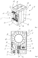
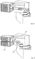
- the storage device has, as components, a housing 2, an input / output device 3, a transport container opening device 4 ( Fig. 4 ), a transport container handling device 5 ( Fig. 2 ), an object handling device 6, an object storage device 7, a transport container storage device 8, an ID reading / alignment device 9 and optional measuring devices such as a particle detection device 10 ( Fig. 4 ). All components are located inside the housing 2.
- the housing 2 forms with its side walls 14, 15, 16, 17, for example, made of sheet metal, as well as top and bottom walls 18, 19, a closed space.
- the housing is designed in such a way that both the front and the rear can be opened for maintenance purposes.
- the Lateral walls 15, 17 of the housing 2 lying in between, however, are not intended for opening, which is why the storage device 1 can be placed with its side walls next to other factories or next to a factory wall. In this way, a number of storage devices 1 preferred according to the invention with a very large storage capacity can be formed in a small footprint, in which maintenance and rapid emergency access to all components of the respective storage device is nevertheless guaranteed.
- a lower input / output device 3b On a front side of the housing there are two closable openings 20, 21 of a lower input / output device 3b through which objects can be brought in and out.
- two upper input / output devices 3 a Arranged immediately above this opening are two upper input / output devices 3 a, which are provided for the automated introduction of transport containers 22 into the interior of the housing 2 and for execution out of the housing 2.
- the two upper input / output devices 3a are intended to take over transport containers 22 automatically supplied from the factory, for example by an overhead transport system, or to deliver them to this transport container 22 from the storage device 1.
- two "manual" input / output devices 3b Immediately below the two openings are two "manual" input / output devices 3b, on which transport containers 22 are placed manually so that they can then be automatically introduced into the housing 2 by lowering the container.
- the storage device 1 can also be used to output transport containers 22 to the "manual input / output device" from inside the housing 2.
- Input / output devices 3a and 3b of this type are, for example, the test wafer stocker TWS300 already offered by the applicant Tec-Sem AG or the product "Practor 300 with Foup Buffer" previously known.
- a transport container 22 arrives at the transport container opening device 4, which is already completely arranged within the housing 2 and which can in principle be designed in the same way as in FIG EP 0 875 921 A1 for SMIF transport containers.
- the transport container opening device 4 is also in connection with the invention, with which the respective transport boxes can be opened and closed.
- the transport containers reach the transport container opening device 4, for example by means of a rotating device which is preferably located below a plate on which the respective transport container is placed and which rotates the plate by rotating around an axis in the direction of the transport container handling device 5 can grip the respective transport container in this orientation and move it into the system.
- the transport containers have a standardized handling adapter on their upper side, with which they are gripped by the transport container handling device 5.
- the transport container opening device 4 is used for the automated opening and closing of transport containers 22 within the storage device. In the embodiment of the invention shown, it is thus provided that the transport containers, including their contents, are introduced into the interior of the storage device 1 in a sealed manner and are only opened there.
- a buffer 24 for a comparatively small number of transport containers 22 is provided directly above the transport container opening device 4.
- This buffer 24 in which, for example, ten, preferably empty, transport containers 22 can be received, is used to transfer one or more objects particularly quickly into a transport container and to remove them from the storage device.
- the buffer 24 provides a transport container for receiving the corresponding object and for subsequent removal from the storage device practically immediately after a specific object has been requested. In this way, the transfer time for removing a transport container 22 from the transport container storage device 8, which is described in more detail below, to the transport container opening device 4 can be avoided.
- a similar advantage can also be achieved by storing transport containers filled with substrates in the transport container storage area.
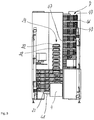
- the transport container handling device 5 is designed as an articulated arm robot 25 which moves along a Z-axis (perpendicular to the plane of the drawing of FIG Fig. 2 ) can be moved lengthways in the vertical direction. With the articulated arm, the articulated arm robot performs 25 movements within XY planes (parallel to the drawing plane of Fig. 2 ) out.
- a passive gripper 26 is attached to the articulated arm, with which the articulated arm robot engages the upper-side handling adapter of the respective transport container 22, which is designed as a SMIF box in the exemplary embodiment.
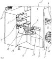
- the object handling device 6 In the opposite corner area of the front wall, on the other side of the transport container opening device 4, the object handling device 6 is located can be moved in the Z direction.
- the articulated arm robot 27 of the object handling device is for transporting and handling substrates 29 arranged in substrate carriers 28 (see, for example, FIG Fig. 6 ) from the transport container opening device 4 to the object storage device 7 and vice versa.
- a passive two-arm gripper 31 is preferably attached to this articulated arm robot 27 for handling individual substrate carriers 28, which can reach through an opening 30 into the transport container opening device 4 in order to pick up a substrate carrier from there or to transfer a substrate carrier 28 to this device .
- other types of handling devices can be provided, for example robots with linear movement axes.
- the fork-shaped gripper 31 is moved under a substrate carrier 28, which is, for example, still arranged in a transport container 22, and by lifting the gripper 31, the substrate carrier is grasped together with the substrates arranged therein and then transported by moving the three robot axes.
- the ID reading / alignment station 9 is arranged in the immediate vicinity of the transport container opening device 4 and the object handling device 6 is in the housing 2, below an operating station 11 arranged on the outside of the housing 2 ( Fig. 1 , Fig. 4 ). With the latter, barcodes attached to or introduced onto substrates 29 or substrate carriers 28 can be automatically detected and the substrates or substrate carriers can thus be identified.
- the ID reading / alignment station can be provided with a camera (not shown in detail) and with suitable evaluation software for evaluating the camera signals. Such optical recognition systems for reading out information contained in bar codes are known per se.
- the objects can optionally be brought into a position by a rotary movement in front of the camera 32 of the station 9 in which the camera 32 can read the barcode or some other means of identification. If no barcode is recognized on one of the respective side surfaces of the object during the first reading process, it can be assumed that this is in a position rotated by 90 °, 180 ° or 270 °. With the device 9, objects arranged thereon can be transferred into said rotational position by rotating the device 9 about a vertical Z-axis.
- two spatially separated areas 34, 35 are formed in the housing, in which different clean room conditions are generated.
- This is a lower area 34 for the transport container storage device 8 and the transport container handling device 5 and around an upper area 35 for the object storage device 7 and for all other components of the storage device that come into direct contact with the objects, such as the ID reading station 32 and the object handling device 6.
- an atmosphere created that meets the highest clean room requirements for example clean room conditions as described in the standard 14644-1 "Classification of Air Cleanliness" ISO: 1.
- the lower area 34 only fulfills less demanding clean room conditions, which is sufficient, however, since no objects get into this area, especially not openly stored objects, as is the case in the upper area.
- the two areas are separated from one another by a horizontal partition 37.
- Both the transport container storage device 8 and the object storage device 7 are at least approximately as hollow cylindrical carousels 38, 39 ( Fig. 5 ), which are rotatable about a common vertical axis of rotation 40.
- the two carousels 38, 39 can each be rotated independently of one another with their own drive.
- the two storage devices 7, 8 can also be rotated simultaneously in opposite directions of rotation about the axis of rotation 40.
- only one common drive can be provided for both carousels, by means of which both carousels can only be rotated together.
- movements that are independent of one another can also be generated with just one drive which, for example, acts selectively on one or the other storage device through a switching process or a clutch.
- the electric drive 41 of the lower carousel 38 is shown, which is arranged in the bottom area of the housing 2 and on whose output shaft (not shown in detail) there is a belt pulley.
- An endless belt guided around the belt pulley is also guided around a pulley with a significantly larger diameter than the belt pulley, the axis of rotation of the disk being aligned with the vertical axis of rotation 40 of the carousel 38.
- the drive movement of the electric drive 41 is thus reduced transferred to the transport container storage device 8.
- a basically similar device for driving the carousel designated by 39 can be provided in the upper region 35. By switching the direction of rotation of the respective electric drive, both storage devices can be rotated in both directions of rotation.
- the transport container storage device 8 has on its outer circumferential surface a multiplicity of receptacles for transport containers 22, which are arranged horizontally and in a ring next to one another in the form of several discs 43 arranged one above the other and one above the other in the carousel 38.
- This configuration results in a matrix-like arrangement of receptacles for transport containers 22.
- FIG Fig. 5 The embodiment shown, for example, six ring-shaped rows are provided by six disks 43, in each of which a holding capacity of twelve receptacles is provided for one transport container 22 each. This results in a total capacity of 72 transport containers.
- the transport container storage device 8 is supplied with nitrogen or clean air from a clean air supply arranged under the ceiling wall 18 of the housing 2 ( Fig. 1 ).
- a fan filter unit 44 is fed from top to bottom approximately in the middle of the upper carousel 39 ( Fig. 5 ) directed gas flow generated. Due to the direction of the gas flow and an overpressure in the upper area 35 as well as through feed-throughs (not shown in detail) through the horizontal partition 37, the clean air can reach the lower area 34 after it has flowed through the upper area 35.
- the leadthroughs can be designed, for example, as a perforation of the partition wall 37.
- a separate (pure) gas supply in particular for nitrogen, can also be provided for each receptacle.
- the connections for gas purging of the containers 22, which are already known from certain transport containers 22, can be connected to this, whereby long-term storage, in particular under a nitrogen atmosphere, is also possible for objects remaining in the transport containers.
- the receptacle 42 in question of the transport container storage device 8 is transferred into a predetermined rotary access position by means of the electric drive 41.
- the transport container handling device 5 is moved in relation to the Z axis to a height that corresponds to the Z position of the respective receptacle 42.
- the gripper is moved into the access position by a movement of the articulated arm of the robot. It can advantageously be provided that all recordings of a line or slice 43 are transferred to the same access position for one access.
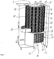
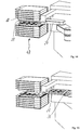
- the object storage device 7 arranged above the transport container storage device 8 has a plurality of ring-shaped shelves 46 arranged parallel one above the other, the number of which can be changed.
- the same number of storage modules 47 which are explained in greater detail below, is arranged on each shelf 46, each storage module 47 being provided with ten storage elements 48 stacked on top of one another.
- the storage elements 48 of this embodiment are ring-shaped, self-contained and approximately quadrangular.
- each storage element 48 is provided for receiving and storing only one object or substrate carrier 28.
- Each storage element 48 is provided with a storage area 48a and with a storage area 48b.
- the storage area 48a is designed in such a way that the respective storage element 48 is suitable for arrangement, in particular for stacking, on a base or on the storage element 48 arranged below it.
- an upper side of the storage area 48a is provided so that a storage element following up in the stack is arranged on it.
- the storage area 48b is used to accommodate a storage object.
- the basic structure of such storage elements 48 and storage modules 47 or storage towers formed with them as well as their handling is already in the WO 2005/006407 A1 and CH 01150/05 by the same applicant.
- each storage element 48b of each storage element has on an inner side on two mutually opposite sides two mutually parallel webs 49 on which a substrate carrier 28 rests.
- the webs 49 can yield at least slightly elastically against the weight of the substrate carrier.
- An underside of a substrate carrier 28 received in this way by a storage element is located at least slightly above a lower standing surface of its storage element 48, with which it rests against a storage element 48 located below.
- each storage element 48 has a centering element 50 on two of its opposite side edges running parallel to one another.
- Each of the centering elements 50 is directed obliquely outward with respect to a viewing direction from top to bottom.
- the centering elements 50 each have an inner and an outer, essentially flat, centering surface 51, 52.
- the two inner centering surfaces of the respective upper storage element 48 rest against the two outer centering surfaces 52 of the storage element 48 arranged below.
- a self-centering of the storage elements in the storage module 47 takes place due to the two centering elements 50 of each storage element 48 arranged in a cone-like manner.
- the storage elements 48 each form a continuous channel 53 on one side of each storage module 47, through which clean room air (filtered air or nitrogen) can be passed through the storage module 47 from bottom to top.
- a rotary feedthrough, not shown, for the clean room air takes place at the lower or upper end of the Carousels 39 into a compressed air line, not shown in detail, of the carousel of the object storage device 7.
- the supply is divided up with compressed air lines leading to the individual storage modules, to which the respective lowermost storage element of a storage module is connected.
- a vertical particle barrier is formed in each storage module 47 through openings (not shown) in the channel 53 directed towards the substrates.
- the stacked storage elements 48 each form a gap between two consecutive storage elements through which the gas under pressure in the channel 53 can flow in a substantially horizontal direction over the substrate carriers 28 and substrates 29. This can help to ensure that the storage objects are flushed with clean air or nitrogen while the substrates are in storage, thus preventing contamination with particles or eliminating existing contamination.
- the storage module 47 of the respective substrate carrier 28 is rotated by means of the electric drive of the carousel 39 in relation to a rotative position of the carousel into an access position for the object handling device 6.
- the gripper of the articulated arm robot 27 and a fork-shaped module opener 55 ( Figures 10 to 16 ) be transferred in the Z direction to the required access height for the respective substrate carrier 28 and immediately in front of the corresponding storage module 47 in relation to the XY plane.
- the module opener 55 can be moved linearly in both the Z and X directions.
- the mobility of the module opener 55 and the object handling device in the Z direction can preferably be generated by a common drive, which reduces the structural, in particular the mechanical, effort of the storage device.
- the module opener 55 with its two forks moves laterally from the centering elements 50 into the storage module and lifts the storage element, which is located directly above the substrate carrier 28 to be removed ( Figures 10 to 13 ).
- the fork-shaped gripper 31 picks up the respective substrate carrier 28 between its fork, lifts it in relation to its storage element 48 and removes it from the storage module ( Fig. 15 , 16 ).
- the module opener 55 can now be lowered again and the storage module 47 can thereby be closed ( Fig. 16 ).
- such a storage medium can also be introduced into a specific storage element of the storage module 47.
- a substrate carrier can also be used for the particle detection device 10 ( Fig. 4 ) transferred, handed over to them and removed from this again after the inspection.
- a particle detection device can, for example, according to the method in FIG WO 02/01292 A1 described particle detection device be configured.
- any other particle detection device that can be integrated into the housing of the storage device can in principle also be used in connection with the present invention.
- the storage device is also provided with a control device, the computer and control software of which coordinates the individual components of the storage device with one another, stores data recorded by the components or other sensors and, if necessary, makes it available to other components.
- the control device can be connected to a higher-level factory control.
- the operating station 11 of the control device is, for example, in Fig. 1 recognizable.
- the storage modules 47 can have base and cover elements 56, 57 ( Fig. 7 ) and thereby simultaneously form an independent storage and transport container as a whole, with which the objects can be transported in a normal factory environment.
- This system opens up the possibility of removal, especially in an emergency of substrates or if maintenance work has to be carried out inside the storage area. If a substrate is required in the event of a machine failure, it can be accessed very easily.
- the side wall on the rear side which is designed as a door, is opened and the drive of the carousel 39 can be released with a manually operated coupling.
- the carousel 39 can then be rotated to the correct position by hand and the storage module 47 with the required substrate can now be removed from the device as a whole.
- the storage module can and should be transported in the closed state through the normal factory environment and only opened at a clean room workplace in order to manually reload the corresponding substrate into a transport container.
- the substrates are completely in a perfect clean room environment.
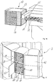
- FIG. 17 a further embodiment according to the invention is shown. To avoid repetition, only essential differences from the exemplary embodiment in FIG Figures 1 to 16 received. In principle, identical components are given the same reference numerals.
- Fig. 17 differs from the first exemplary embodiment primarily in that the object storage device 7 is configured differently.
- the possible embodiment of the object storage device 7 is shown in detail, in which box-shaped compartments 60 are provided in several rings, in each of which several receptacles 61 for the horizontal arrangement of substrates 29 or one substrate carrier 28 are formed.
- Each compartment 60 can be closed with its own laterally pivotably hinged and sealed door 62.
- Each compartment 60 is permanently flushed by means of a nitrogen connection, not shown in detail. When a substrate carrier 28 is removed or inserted, the nitrogen content temporarily drops to the level of the ambient air and increases again as soon as the door is closed.
- a pneumatically driven device for example, whose pneumatic cylinder receives actuation signals from the control device, can be provided for opening and closing the doors.
- ⁇ b> List of reference symbols ⁇ /b> 1 Storage device 26th Grapple 2 casing 27 Articulated robots (of 6) 3 Input / output device 28 Substrate carrier 3a upper input / output device 29 Substrate 3b lower input / output device 31 Grapple 4th Transport container opening device 32 camera 33 Alignment device 5 Transport container handling device 34 lower area 35 upper area 6th Object handling device 37 horizontal partition 38 lower carousel 7th Object storage facility 39 upper carousel 8th Transport container storage device 40 vertical axis of rotation 41 electric drive 9 ID reader / alignment device 42 admission 43 disc 10 Particle detection device 44 Fan filter unit 11 Operator station 46 shelf 14th Side wall 47 Memory module 15th Side wall 48 Storage element 16 Side wall 48a storage area 17th Side wall 48b Storage area 18th Ceiling wall 49 web 19th Bottom wall 50 Centering element 20th opening 51 inner centering surface 21
Description
Die Erfindung betrifft eine Lagervorrichtung für Objekte in der Fertigung von Substraten, insbesondere von Substraten für elektronische Bauteile wie beispielsweise LCD-Displays, wobei die Lagervorrichtung mit einem Gehäuse versehen ist, das zumindest einen im wesentlichen abgeschlossenen Raum zur Lagerung der Objekte ausbildet, eine Reinlufteinrichtung aufweist, mit der zumindest innerhalb eines Abschnitts des Gehäuses eine Reinluftatmosphäre erzeugbar ist, mit mindestens einer Eingabe-/Ausgabe-Einrichtung versehen ist, mittels der Objekte in das Innere des Gehäuses ein- oder aus dem Inneren ausführbar sind, mindestens eine Handhabungseinrichtung aufweist, mit der Objekte im Inneren des Gehäuses handhabbar sind, und Objektaufnahmen innerhalb des Gehäuses aufweist, in denen Objekte außerhalb von Transportbehältern zwischenlagerbar sind.The invention relates to a storage device for objects in the manufacture of substrates, in particular substrates for electronic components such as LCD displays, the storage device being provided with a housing which forms at least one essentially closed space for storing the objects and has a clean air device , with which a clean air atmosphere can be generated at least within a section of the housing, is provided with at least one input / output device, by means of which objects can be moved into or out of the interior of the housing, has at least one handling device with which Objects can be handled inside the housing, and has object receptacles inside the housing, in which objects can be temporarily stored outside of transport containers.
In der industriellen Fertigung von elektronischen Bauteilen, wie beispielsweise LCD-Displays oder von anderen Flachbildschirmen oder Substraten etc., müssen regelmäßig Objekte innerhalb einer Fabrik transportiert und zwischengelagert werden. Hierfür sind zum einen Transportbehälter vorgesehen, in denen die Objekte gegen äußere Einflüsse sicher angeordnet und transportiert werden. Als Transportbehälter werden häufig sogenannte SMIF- und FOUP-Boxes eingesetzt. Zum anderen werden die Objekte, nach bzw. bevor sie in der Fabrik transportiert werden, in einer Lagervorrichtung, wie eingangs beschrieben, zwischengelagert.In the industrial production of electronic components, such as LCD displays or other flat screens or substrates, etc., objects regularly have to be transported and temporarily stored within a factory. For this purpose, on the one hand, transport containers are provided in which the objects are safely arranged and transported against external influences. So-called SMIF and FOUP boxes are often used as transport containers. On the other hand, after or before they are transported in the factory, the objects are temporarily stored in a storage device, as described above.
Derartige Lagervorrichtungen weisen in der Regel ein Gehäuse auf, das einen oder mehrere voneinander abgetrennte Räume ausbildet. Um die Objekte in diesen zumindest einen Raum zu überführen bzw. zu entnehmen weisen die Lagervorrichtungen eine verschließbare Öffnung auf. Üblicherweise werden die Objekte maschinell oder manuell aus den Transportbehältern entnommen, bevor sie in den Raum überführt werden. Zum Transport innerhalb der Fabrik werden die Objekte dann wieder aus der Lagervorrichtung entnommen und ausserhalb des Raumes in die ebenfalls ausserhalb der Lagervorrichtung zwischenzeitlich gelagerten Transportbehälter eingesetzt. Aus Gründen der Aufrechterhaltung der Reinraumbedingungen wird üblicherweise angestrebt, die Objekte und die Transportbehälter getrennt voneinander aufzubewahren. Zudem sind die Transportbehälter teuer und voluminös. Wenn in einer Fabrik sehr viele Objekte benutzt werden, dann ist auch üblicherweise die entsprechende Anzahl benötigter Transportbehälter sehr hoch.Storage devices of this type generally have a housing which forms one or more separate spaces. In order to transfer or remove the objects in this at least one space, the storage devices have a closable opening. The objects are usually removed from the transport containers by machine or manually before they are transferred into the room. For transport within the factory, the objects are then removed again from the storage device and outside of the room in those that have also been stored outside the storage device in the meantime Transport container used. For reasons of maintaining the clean room conditions, the aim is usually to store the objects and the transport containers separately from one another. In addition, the transport containers are expensive and bulky. If a large number of objects are used in a factory, the corresponding number of transport containers required is usually very high.
Es sind allerdings auch andere Lösungen bekannt geworden, bei denen die Substrate zusammen mit ihren Transportbehältern der Lagervorrichtung zugeführt werden und erst innerhalb der Lagervorrichtung aus dem jeweiligen Transportbehältern entnommen werden. Hier ist vorgesehen, nach der Entnahme der Objekte die Transportbehälter in einem ersten Raum und die Objekte in einem zweiten Raum zu lagern. Die beiden Räume sind durch zum Gehäuse gehörende vertikale Trennwände voneinander getrennt. An dieser Lösung kann jedoch nicht zufrieden stellen, dass sie eine relativ grosse Stellfläche benötigt. Ein weiterer Nachteil ist die konzeptbedingte aufwendige Reinluftversorgung für vergleichsweise grosse Räume.However, other solutions have also become known in which the substrates are fed to the storage device together with their transport containers and are only removed from the respective transport containers within the storage device. Provision is made here for the transport containers to be stored in a first room and the objects in a second room after the objects have been removed. The two rooms are separated from each other by vertical partitions belonging to the housing. However, the fact that it requires a relatively large floor space is unsatisfactory in this solution. Another disadvantage is the complex clean air supply for comparatively large rooms due to the concept.
Aus der
Die Erfindung liegt deshalb die Aufgabe zugrunde, eine Möglichkeit zu schaffen, durch die Objekte aus der Fertigung von elektronischen Bauteilen und ihre Transportbehälter zum Transport der Objekte in einer Weise zwischengelagert werden können, durch die für die Zwischenlagerung nur eine möglichst kleine Stellfläche in der Fabrik benötigt wird.The invention is therefore based on the object of creating a way through which objects from the manufacture of electronic components and their transport containers for transporting the objects can be temporarily stored in a way that only requires the smallest possible floor space in the factory for the temporary storage becomes.
Diese Aufgabe wird bei einer Lagervorrichtung gemäß dem Oberbegriff durch die Merkmale von Patentanspruch 1 gelöst. Hierbei ist vorgesehen, dass im gleichen Gehäuse der Lagervorrichtung zwei zumindest teilweise übereinander angeordnete Bereiche ausgebildet sind, wobei ein erster Bereich für eine Objekt-Speichereinrichtung und ein zweiter Bereich für eine Transportbehälter-Speichereinrichtung vorgesehen ist. Die vorliegende Erfindung eignet sich für jegliche Objekte bzw. Substrate aus dem Bereich der Fertigung von elektronischen Bauteilen, Komponenten, Geräten und dergleichen, die innerhalb einer Fertigungsfabrik üblicherweise in Transportbehältern transportiert werden. Die Verwendbarkeit der Erfindung ist unabhängig von der Form (rund, oval rechteckig, achteckig etc.) der Objekte bzw. Substrate und deren Werkstoffe. Des Weiteren eignet sich die Erfindung auch für die Lagerung von in Objektträgern angeordneten Objekte. In einem solchen Anwendungsfall werden die Objekte vorzugsweise zusammen mit ihren Objektträgern in die Objekt-Speicher-einrichtung eingeführt und dort zur Lagerung aufgenommen.In the case of a storage device according to the preamble, this object is achieved by the features of patent claim 1. It is provided here that two at least partially superposed areas are formed in the same housing of the storage device, a first area being provided for an object storage device and a second area for a transport container storage device. The present invention is suitable for any objects or substrates from the field of manufacturing electronic parts, components, devices and the like, which are usually transported in transport containers within a manufacturing factory. The usability of the invention is independent of the shape (round, oval, rectangular, octagonal, etc.) of the objects or substrates and their materials. Furthermore, the invention is also suitable for the storage of objects arranged in object carriers. In such an application, the objects are preferably introduced into the object storage device together with their object carriers and are taken up there for storage.
Erfindungsgemäss kann somit vorgesehen sein, die Objekte und die zu ihrem Transport vorgesehenen Transportbehälter zwar voneinander getrennt aber dennoch örtlich nahe zueinander innerhalb des gleichen Gehäuses zu lagern. Sowohl die Objekte als auch die Transportbehälter können mittels der Lagervorrichtung somit für eine vorbestimmte oder eine unbestimmte Zeit so lange dem Fertigungsprozess entnommen werden, bis sie in letzterem wieder benötigt werden. Die Objekte können hierzu aus den Transportbehältern entnommen werden. Hierdurch ist es möglich, chemische Verunreinigungen der Substrate zu vermeiden, die beispielsweise durch Ausgasung der Kunststoffe der Transportbehälter entstehen können. Es hat sich gezeigt, dass insbesondere bei einer längeren Lagerung von Substraten in Transportbehältern solche Kontaminationen entstehen können. Durch die zusätzlich gegebene örtliche Nähe der Lagerstellen der Objekte einerseits und der Transportbehälter andererseits können die Objekte trotz ihrer sicheren kontaminationsfreien Lagerung schnell und flexibel dem Fertigungsprozess wieder zugeführt werden.According to the invention, it can thus be provided that the objects and the transport containers provided for their transport are stored separately from one another but nonetheless locally close to one another within the same housing. Both the objects and the transport containers can thus be removed from the manufacturing process by means of the storage device for a predetermined or an indefinite period of time until they are needed again in the latter. For this purpose, the objects can be removed from the transport containers. This makes it possible to avoid chemical contamination of the substrates, which can arise, for example, from outgassing of the plastics in the transport containers. It has been shown that such contaminations can arise, in particular when substrates are stored in transport containers for a longer period of time. Due to the additional local proximity of the storage locations of the objects on the one hand and the transport containers on the other hand, the objects can be returned to the production process quickly and flexibly despite their safe, contamination-free storage.
Zudem ist es mit der Erfindung möglich, nur so viele Transportbehälter zu bevorraten, wie üblicherweise in der Fabrik für gleichzeitig im Umlauf befindliche Substrate benötigt werden. Anders als bisher, muss die Anzahl an Transportbehältern nicht anhand der Anzahl an insgesamt vorhandenen und zu speichernden Substrate bestimmt werden.In addition, it is possible with the invention to store only as many transport containers as are usually required in the factory for substrates that are in circulation at the same time. Unlike in the past, the number of transport containers does not have to be determined on the basis of the total number of substrates that are present and to be stored.
Es ist hierbei ausserdem vorgesehen, dass die zur Aufnahme der Objekte vorgesehene Objekt-Speichereinrichtung und die Transportbehälter-Speichereinrichtung, in der Transportbehälter zwischengelagert werden sollen, zumindest im wesentlichen - vorzugsweise vollständig - übereinander angeordnet sind. Hierdurch benötigt die Lagervorrichtung nur eine besonders geringe Stellfläche. Als besonders günstig hat sich hierbei eine Anordnung gezeigt, bei der sich die Objekt-Speichereinrichtung über der Transportbehälter-Speichereinrichtung befindet. Durch eine solche Anordnung ist trotz der räumlichen Nähe von Transportbehältern einerseits und daraus entnommenen Objekten andererseits, mit geringem technischen Aufwand für die Objekt-Speichereinrichtung eine vorteilhafte Reinluftversorgung von oben über eine Deckenwand der Lagervorrichtung möglich.It is also provided here that the object storage device provided for receiving the objects and the transport container storage device in which the transport containers are to be temporarily stored are arranged at least essentially - preferably completely - one above the other. As a result, the storage device only requires a particularly small footprint. An arrangement in which the object storage device is located above the transport container storage device has been shown to be particularly favorable. With such an arrangement, despite the spatial proximity of transport containers on the one hand and objects removed therefrom, on the other hand, an advantageous clean air supply from above via a ceiling wall of the storage device is possible with little technical effort for the object storage device.
Die beiden Bereiche sollten sich zwar im gleichen Gehäuse befinden, sind aber vorzugsweise voneinander abgetrennt, wodurch in den Bereichen voneinander getrennte bzw. isolierte Atmosphären erzeugbar sind. Insbesondere im Bereich der Objekt-Speichervorrichtung soll die Erzeugung und Aufrechterhaltung einer Atmosphäre möglich sein, die hohe Reinheitsanforderungen erfüllt. Die Transportbehälter-Speichereinrichtung kann durch eine zumindest näherungsweise und abschnittsweise horizontal verlaufende Trennwand innerhalb des Gehäuses von der Objekt-Speichereinrichtung getrennt sein. Ein gemeinsamer Antrieb für die beiden Speichereinrichtungen kann hierbei durch die Trennwand hindurchgeführt sein.The two areas should be in the same housing, but are preferably separated from one another, so that separate or isolated atmospheres can be generated in the areas. In the area of the object storage device in particular, it should be possible to generate and maintain an atmosphere that meets high purity requirements. The transport container storage device can be separated from the object storage device by a partition wall running at least approximately and in sections horizontally within the housing. A common drive for the two storage devices can be passed through the partition.
Mit Vorteil können innerhalb des Raumes der Lagervorrichtung die Objekte und die Transportbehälter mit jeweils einer Handhabungseinrichtung in die jeweiligen Aufnahmen eingesetzt und aus ihnen entnommen werden. Um eine große Anzahl an Objekten und Transportbehältern speichern zu können und trotzdem mit besonders wenigen Handhabungsschritten und mit kurzen Verfahrwegen auszukommen, kann ein drehbares Karussell vorgesehen sein, das mit den Objektaufnahmen und den Aufnahmen für die Transportbehälter versehen ist. Eine solche Anordnung ermöglicht auch mit geringem technischen Aufwand bei Bedarf eine Erhöhung der Anzahl der Objektaufnahmen durch Austausch gegen Aufnahmen für Transportbehälter oder umgekehrt vornehmen zu können. Eine Erweiterung der Kapazität ist auch durch eine Ergänzung von Aufnahmen möglich, beispielsweise durch Aufsetzen von weiteren Objektaufnahmen auf die bis dahin oberste Objektaufnahmereihe des Karussells.Advantageously, within the space of the storage device, the objects and the transport containers can each be inserted into and removed from the respective receptacles with a handling device. To be able to store a large number of objects and transport containers and still be special a few handling steps and with short travel distances, a rotatable carousel can be provided, which is provided with the object receptacles and the receptacles for the transport container. Such an arrangement makes it possible, if necessary, to increase the number of object receptacles by exchanging receptacles for transport containers or vice versa with little technical effort. The capacity can also be expanded by adding additional recordings, for example by placing additional object holders on the top row of object holders of the carousel.
Das Einsetzen und die Entnahme von Objekten und von Transportbehältern in bzw. aus jeweils einer Aufnahme kann mittels innerhalb des Gehäuses angeordneten Handhabungseinrichtungen erfolgen. Hierbei ist in vorteilhafter Weise jeweils eine Handhabungseinrichtung den Transportbehältern und eine Handhabungseinrichtung den Objekten zugeordnet. Zur Ausführung der hierfür erforderlichen Relativbewegungen zwischen Greifern der Handhabungseinrichtungen und der jeweiligen Aufnahme kann in die Aufnahmen mindestens eine Bewegungsachse gelegt sein, beispielsweise eine Drehbewegung um die vertikale Z-Achse. Die Handhabungseinrichtung kann vorzugsweise Verfahrbewegungen zumindest in Richtung der Z- und der Y-Achse ausführen, um den Greifer in der Höhe der jeweiligen Aufnahme zu positionieren und auf diese zu- und weg zu bewegen.Objects and transport containers can be inserted and removed in or from a respective receptacle by means of handling devices arranged within the housing. In this case, one handling device is advantageously assigned to the transport containers and one handling device is assigned to the objects. To carry out the relative movements required for this between grippers of the handling devices and the respective receptacle, at least one movement axis can be placed in the receptacles, for example a rotary movement about the vertical Z-axis. The handling device can preferably perform traversing movements at least in the direction of the Z and Y axes in order to position the gripper at the level of the respective receptacle and to move it towards and away from it.
Innerhalb der Lagervorrichtung kann mit Vorteil vorgesehen sein, dass ein Antrieb der Handhabungseinrichtung der Objekt-Speichereinrichtung unterhalb einer Objekthandlingebene dieser Handhabungseinrichtung angeordnet ist. Die Objekthandlingebene kann durch eine Stelle bzw. eine Ebene des Greifers vorgegeben sein, an welcher dieser Greifer das Objekt aufnimmt. Diese Anordnung bietet den Vorteil, dass der gesamte Objekt-Speicherbereich bis knapp unter die Decke des Gehäuses mit dieser Handhabungseinrichtung erreicht werden kann. Da die unterste, anzufahrende Stelle für diese Handhabungseinrichtung auf Höhe einer Objektentnahme aus der jeweiligen Transportbox vorgesehen sein kann, hat die Antriebsmechanik zum Boden hin genügend Freiraum.Within the storage device it can advantageously be provided that a drive of the handling device of the object storage device is arranged below an object handling level of this handling device. The object handling level can be specified by a point or a level of the gripper at which this gripper picks up the object. This arrangement offers the advantage that the entire object storage area can be reached just below the ceiling of the housing with this handling device. Since the lowest point to be approached for this handling device can be provided at the level of an object being removed from the respective transport box, the drive mechanism has sufficient free space towards the floor.
Im Gegensatz dazu kann ein Antrieb der Handhabungseinrichtung für die Transportbehälter-Speichereinrichtung stets oberhalb der Handlingebene bzw. -stelle angeordnet sein, die sich durch den Greifer der Transportbehälter-Handhabungseinrichtung ergibt. Dies ermöglicht die Nutzung des Speicherbereichs für die Transportbehälter bis hinab zum Boden des Gehäuses bzw. bis nahe zum Untergrund auf dem die Lagervorrichtung steht. Da es in bevorzugten Ausführungsformen nicht erforderlich ist, dass die Handhabungseinrichtung der Transportbehälter-Speichereinrichtung in Z-Richtung bis zur Gehäusedecke verfahrbar ist, ergibt sich oberhalb der Objekthandlingebene genügend Raum für die Antriebsmechanik. Eine solche bevorzugte erfindungsgemässe Ausgestaltung der Lagervorrichtung ermöglicht die vollständige Ausnutzung der Höhe der Lagervorrichtung mit Speicherplätzen. Die Speicherkapazität der Lagervorrichtung kann hierdurch erheblich gesteigert werden.In contrast to this, a drive of the handling device for the transport container storage device can always be arranged above the handling level or point which results from the gripper of the transport container handling device. This enables the storage area to be used for the transport containers down to the bottom of the housing or as far as the ground on which the storage device stands. Since in preferred embodiments it is not necessary for the handling device of the transport container storage device to be movable in the Z direction up to the housing ceiling, there is sufficient space for the drive mechanism above the object handling level. Such a preferred embodiment of the storage device according to the invention enables full utilization of the height of the storage device with storage spaces. The storage capacity of the storage device can be increased considerably as a result.
In einer zweckmäßigen erfindungsgemäßen Ausgestaltung kann nur ein Antrieb für beide Karussellteile vorgesehen sein. In einer ersten Variante können mit dem Antrieb beide Karussellteile simultan bewegt werden. In einer zweiten Variante sind die beiden Karussellteile unabhängig voneinander und gegebenenfalls auch in unterschiedliche Drehrichtungen bewegbar.In an expedient embodiment according to the invention, only one drive can be provided for both carousel parts. In a first variant, both carousel parts can be moved simultaneously with the drive. In a second variant, the two carousel parts can be moved independently of one another and optionally also in different directions of rotation.
In einer bevorzugten Ausführungsform der Erfindung kann mit Vorteil für den Bereich der Objektaufnahmen und den Bereich der Transportbehälter eine gemeinsame Reinlufteinrichtung vorgesehen sein, deren Reinluft beide Bereiche durchströmt. Diese Reinlufteinrichtung kann insbesondere in der Weise ausgestaltet sein, dass mittels Luftleitmittel ein Reinluftstrom nacheinander beide Bereiche durchströmt. Alternativ hierzu können auch zwei Teilströme der Reinluft erzeugt werden, die jeweils nur einem Bereich zugeordnet sind. Im Zusammenhang mit der Erfindung sollen unter "Reinluft" nicht nur Gase verstanden werden, die zumindest in etwa der Umgebungsluft entsprechen. Unter dem Begriff "Luft" soll im Zusammenhang mit der Erfindung jedes Gas bzw. Gaszusammensetzung verstanden werden, das bzw. die als Gasstrom zur Schaffung und Aufrechterhaltung von Rein- oder Reinstraumbedingungen innerhalb der Lagervorrichtung geeignet ist. Der Begriff Luft soll insbesondere auch reinen Stickstoff oder reine Gase mit einem hohen Stickstoffanteil erfassen.In a preferred embodiment of the invention, a common clean air device can advantageously be provided for the area of the object receptacles and the area of the transport containers, the clean air of which flows through both areas. This clean air device can in particular be designed in such a way that a clean air stream flows through both areas one after the other by means of air guiding means. As an alternative to this, two partial streams of the clean air can also be generated, each of which is only assigned to one area. In connection with the invention, “clean air” should not only be understood to mean gases which at least approximately correspond to the ambient air. In connection with the invention, the term “air” should be understood to mean any gas or gas composition which is suitable as a gas flow for creating and maintaining clean room conditions within the storage device. The term air is intended in particular also record pure nitrogen or pure gases with a high nitrogen content.
Durch diese erfindungsgemäß mögliche Ausgestaltung können mit dem gleichen Reinluftstrom sowohl bei den Objekten als auch bei den zwischengelagerten Transportbehältern Reinraumbedingungen erzeugt werden. Hierbei kann von besonderem Vorteil sein, wenn der gleiche Reinluftstrom zuerst durch den Bereich der Objekte und danach durch den Bereich der Transportbehälter geführt wird.This configuration, which is possible according to the invention, allows clean room conditions to be generated with the same clean air flow both in the case of the objects and in the case of the temporarily stored transport containers. It can be of particular advantage here if the same stream of clean air is first guided through the area of the objects and then through the area of the transport containers.
Die in einer Fabrik benötigte Logistik kann stark entlastet werden, wenn in der Lagervorrichtung auch Messgeräte wie Partikelscanner, Schichtdickenmessgerät und/oder sonstige Metrology-Komponenten eingebaut sind, mit denen Objekte vor oder nach der Lagerung vermessen werden können. Sämtliche hierzu erforderlichen Handhabungsschritte finden dann innerhalb des Gehäuses und nicht in einer Vielzahl von Einzelkomponenten innerhalb der Fabrik statt, die jeweils einzeln von einem Fabrikleitrechner angesteuert und miteinander koordiniert werden müssten.The logistics required in a factory can be greatly relieved if measuring devices such as particle scanners, layer thickness measuring devices and / or other metrology components are installed in the storage device, with which objects can be measured before or after storage. All of the handling steps required for this then take place within the housing and not in a large number of individual components within the factory, each of which would have to be individually controlled by a factory control computer and coordinated with one another.
Eine besondere Flexibilität ergibt sich bei weiteren bevorzugten Ausführungsformen der Erfindung, bei denen die Lagervorrichtung als sogenannte Stand-alone Vorrichtung vorgesehen ist, die in ihrem Gehäuse keine Prozeßanlage enthält, mit der die Objekte im Zusammenhang mit ihrer Fertigung be- oder verarbeitet werden. Der Standort einer solchen Stand-alone Vorrichtung innerhalb einer Fabrik kann ohne größeren Aufwand und im wesentlichen nur nach logistischen Gesichtspunkten jederzeit optimiert werden. Selbstverständlich ist jedoch auch möglich, eine erfindungsgemäße Lagervorrichtung entweder an eine Prozeßanlage anzuschließen oder eine Prozeßanlage in die Lagervorrichtung zu integrieren.A particular flexibility results in further preferred embodiments of the invention in which the storage device is provided as a so-called stand-alone device, which does not contain a process system in its housing with which the objects are processed or processed in connection with their production. The location of such a stand-alone device within a factory can be optimized at any time without great effort and essentially only from a logistical point of view. Of course, however, it is also possible to either connect a storage device according to the invention to a process system or to integrate a process system into the storage device.
Weitere bevorzugte Ausgestaltungen der Erfindung ergeben sich aus den Ansprüchen, der Beschreibung und der Zeichnung.Further preferred embodiments of the invention emerge from the claims, the description and the drawing.
Die Erfindung wird anhand von in den Figuren rein schematisch dargestellten Ausführungsbeispielen näher erläutert, es zeigen:
- Fig. 1
- eine perspektivische Darstellung einer erfindungsgemäßen Lagervorrichtung;
- Fig. 2
- eine Darstellung von oben, in die Lagervorrichtung aus
Fig. 1 ; - Fig. 3
- eine Seitenansicht der geöffneten Lagervorrichtung aus
Fig. 1 ; - Fig. 4
- eine perspektivische Teildarstellung der Lagervorrichtung mit einer darin angeordneten Objekt-Handhabungseinrichtung;
- Fig. 5
- eine weitere perspektivische Teildarstellung der Lagervorrichtung;
- Fig. 6
- eine perspektivische Darstellung eines Speicherelements mit darauf angeordnetem Substratträger;
- Fig. 7
- eine geschnittene perspektivische Darstellung eines mit Speicherelementen gemäss
Fig. 6 gebildeten Speichermoduls; - Fig. 8
- eine Seitenansicht eines Speichermoduls;
- Fig. 9
- eine Seitenansicht eines geöffneten Speichermoduls;
- Fig.10- 16
- perspektivische Darstellungen von Handhabungsschritten eines Modulöffners und einer Objekt-Handhabungseinrichtung zur Entnahme eines Substratträger aus einem Speichermodul;
- Fig.17
- eine perspektivische Teildarstellung einer alternativen Objekt-Speichereinrichtung;
- Fig. 1
- a perspective view of a storage device according to the invention;
- Fig. 2
- a representation from above, in the storage device
Fig. 1 ; - Fig. 3
- a side view of the opened storage device
Fig. 1 ; - Fig. 4
- a perspective partial representation of the storage device with an object handling device arranged therein;
- Fig. 5
- a further perspective partial representation of the storage device;
- Fig. 6
- a perspective view of a memory element with a substrate carrier arranged thereon;
- Fig. 7
- a cut perspective view of a memory elements according to FIG
Fig. 6 formed memory module; - Fig. 8
- a side view of a memory module;
- Fig. 9
- a side view of an opened memory module;
- Fig. 10-16
- perspective representations of handling steps of a module opener and an object handling device for removing a substrate carrier from a storage module;
- Fig.17
- a perspective partial representation of an alternative object storage device;
In den
Transportbehälter für solche Objekte, insbesondere Substrate, sind üblicherweise allseitig geschlossen. Die verbreiteste Form von solchen Transportbehältern sind entweder gemäß dem SMIF- oder dem FOUP-Standard (SMIF = Standard Mechanical Interface; FOUP = Front Opening Unified Pod) ausgebildet. SMIF-Transportbehälter weisen eine Haube und einen mit der Haube verschließbaren Boden auf. FOUP-Behälter sind hingegen an einer Frontseite mit einer Öffnung versehen, die mit einem Deckel verschliessbar ist. Die Lagervorrichtung kann prinzipiell zur Aufnahme und Lagerung von Transportbehältern für jeweils nur ein oder für mehrere Lagerungsobjekte, wie beispielsweise Substrate von LCD-Bildschirmen oder andere Substrate ausgebildet werdenTransport containers for such objects, in particular substrates, are usually closed on all sides. The most common form of such transport containers are designed according to either the SMIF or the FOUP standard (SMIF = Standard Mechanical Interface; FOUP = Front Opening Unified Pod). SMIF transport containers have a hood and a base that can be closed with the hood. FOUP containers, on the other hand, have an opening on one front side that can be closed with a lid. The storage device can in principle be designed to receive and store transport containers for only one or for several storage objects, such as substrates of LCD screens or other substrates
Die Lagervorrichtung weist als Komponenten ein Gehäuse 2, eine Ein-/AusgabeEinrichtung 3, eine Transportbehälter-Öffnungseinrichtung 4 (
Das Gehäuse 2 bildet mit seinen beispielsweise aus Blechen bestehenden Seitenwänden 14, 15, 16, 17 sowie Decken- und Bodenwänden 18, 19 einen geschlossenen Raum aus. Das Gehäuse ist hierbei so ausgebildet, dass sowohl die Front- als auch die Rückseite für Wartungszwecke geöffnet werden kann. Die dazwischen liegenden seitlichen Wände 15, 17 des Gehäuses 2 sind hingegen nicht zur Öffnung vorgesehen, weshalb die Lagervorrichtung 1 mit ihren Seitenwänden neben andere Fabrikanlagen oder neben eine Fabrikwand gestellt werden kann. Es kann auf diese Weise insbesondere auf einer geringen Stellfläche eine Reihe von erfindungsgemäss bevorzugten Lagervorrichtungen 1 mit sehr großer Speicherkapazität gebildet werden, bei der die Wartung und ein schneller Notfallzugriff auf sämtliche Komponenten der jeweiligen Lagervorrichtung trotzdem gewährleistet ist.The
An einer Forderseite des Gehäuses sind zwei verschließbare Öffnungen 20, 21 einer unteren Ein-/Ausgabe-Einrichtung 3b vorhanden, durch die Gegenstände ein- und ausgeführt werden können. Unmittelbar oberhalb dieser Öffnung sind zwei obere Ein-/Ausgabeeinrichtung 3a angeordnet, die zur automatisierten Einführung von Transportbehältern 22 in das Innere des Gehäuses 2 sowie zur Ausführung aus dem Gehäuse 2 heraus vorgesehen ist. Die beiden oberen Ein-/Ausgabeeinrichtungen 3a sind dazu bestimmt, automatisiert aus der Fabrik zugeführte Transportbehälter 22, beispielsweise durch ein Overhead-Transportsystem, zu übernehmen bzw. an dieses Transportbehälter 22 aus der Lagervorrichtung 1 abzugeben. Unmittelbar unterhalb der beiden Öffnungen sind zwei "manuelle" Ein-/Ausgabeeinrichtungen 3b vorgesehen, auf denen manuell Transportbehälter 22 plaziert werden, damit diese dann durch Absenken des Behälters automatisiert in das Gehäuse 2 eingeführt werden. Mit der Lagervorrichtung 1 können auch aus dem Inneren des Gehäuses 2 Transportbehälter 22 an die "manuelle Ein-/Ausgabeeinrichtung ausgegeben werden. Derartige Ein-/Ausgabeeinrichtungen 3a und 3b sind beispielsweise durch die von der Anmelderin Tec-Sem AG bereits angebotenen Test Wafer Stocker TWS300 oder das Produkt "Practor 300 mit Foup Buffer" vorbekannt.On a front side of the housing there are two
Von einer der Ein-/Ausgabeeinrichtungen 3a, 3b gelangt ein Transportbehälter 22 zu der sich bereits vollständig innerhalb des Gehäuses 2 angeordneten Transportbehälter-Öffnungseinrichtung 4, die prinzipiell in gleicher Weise ausgebildet sein kann, wie dies in der
Die Transportbehälter gelangen beispielsweise mittels einer Dreheinrichtung, die sich vorzugsweise unterhalb einer Platte befindet, auf welcher der jeweilige Transportbehälter abgestellt wird und die die Platte durch Drehung um eine Achse in Richtung der Transportbehälter-Handhabungseinrichtung dreht, zur Transportbehälter-Öffnungseinrichtung 4. Die Transportbehälter-Handhabungseinrichtung 5 kann den jeweiligen Transportbehälter in dieser Ausrichtung greifen und in das System bewegen. Die Transportbehälter weisen an ihrer Oberseite einen genormten Handlingadapter auf, mit dem sie von der Transportbehälter-Handhabungseinrichtung 5 gegriffen werden.The transport containers reach the transport
Die Transportbehälter-Öffnungseinrichtung 4 dient zum automatisierten Öffnen und Verschliessen von Transportbehältern 22 innerhalb der Lagervorrichtung. Bei der dargestellten Ausführungsform der Erfindung ist somit vorgesehen, dass die Transportbehälter samt ihres Inhalts verschlossen in das Innere der Lagervorrichtung 1 eingeführt und erst dort geöffnet werden.The transport
Wie insbesondere in
In einem insbesondere in
Im gegenüberliegenden Eckbereich der Frontwand befindet sich auf der anderen Seite der Transportbehälter-Öffnungseinrichtung 4 die Objekt-Handhabungseinrichtung 6. Diese ist in prinzipiell gleicher Weise ausgebildet wie die Transportbehälter-Handhabungseinrichtung 5, also auch als in der X-Y-Ebene beweglicher Knickarmroboter 27, der zudem in Z-Richtung verfahrbar ist. Der Knickarmroboter 27 der Objekt-Handhabungseinrichtung ist zum Transport und Handhabung von in Substratträgern 28 angeordneten Substraten 29 (s. beispielsweise
Zum Erfassen eines Substratträgers 28 wird der gabelförmige Greifer 31 unter einen Substratträger 28, der beispielsweise noch in einem Transportbehälter 22 angeordneten ist, gefahren und durch Anheben des Greifers 31 der Substratträger zusammen mit den darin angeordneten Substraten erfasst und nachfolgend durch Bewegung der drei Roboterachsen transportiert.To grasp a
In unmittelbarer Nähe zur Transportbehälter-Öffnungseinrichtung 4 und zur Objekt-Handhabungseinrichtung 6 ist im Gehäuse 2, unterhalb einer aussen am Gehäuse 2 angeordneten Bedienstation 11 (
Wie insbesondere in
Sowohl die Transportbehälter-Speichereinrichtung 8 als auch die Objekt-Speichereinrichtung 7 sind als zumindest näherungsweise als hohlzylindrische Karussells 38, 39 (
Im gezeigten Ausführungsbeispiel ist nur der elektrische Antrieb 41 des unteren Karussells 38 dargestellt, der im Bodenbereich des Gehäuses 2 angeordnet ist und auf dessen nicht näher dargestellten Abtriebswelle sich eine Riemenscheibe befindet. Ein um die Riemenscheibe geführter Endlosriemen ist des Weiteren auch um ein Scheibe mit deutlich grösserem Durchmesser als die Riemenscheibe geführt, wobei die Drehachse der Scheibe mit der vertikalen Drehachse 40 des Karussells 38 fluchtet. Die Antriebsbewegung des elektrischen Antriebs 41 wird somit untersetzt auf die Transportbehälter-Speichereinrichtung 8 übertragen. Für die Objekt-Speichereinrichtung 7 kann im oberen Bereich 35 eine prinzipiell gleichartige Einrichtung zum Antrieb des mit 39 bezeichnete Karussells vorgesehen sein. Durch eine Drehrichtungsumschaltung des jeweiligen elektrischen Antriebs können beide Speichereinrichtungen in jeweils beide Drehrichtungen gedreht werden.In the exemplary embodiment shown, only the
Die Transportbehälter-Speichereinrichtung 8 weist an ihrer äußeren Umfangsfläche eine Vielzahl von Aufnahmen für Transportbehälter 22 auf, die in Form von mehreren übereinander angeordneten Scheiben 43 horizontal und ringförmig nebeneinander und im Karussell 38 übereinander überangeordnet sind. Durch diese Ausgestaltung ergibt sich eine matrixförmige Anordnung von Aufnahmen für Transportbehälter 22. Im in
Im oberen Bereich 35 wird die Transportbehälter-Speichereinrichtung 8 von einem unter der Deckenwand 18 des Gehäuses 2 angeordneten Reinluftversorgung mit Stickstoff oder Reinluft versorgt (
Um auf eine bestimmte Aufnahme 42 zuzugreifen ist vorgesehen, dass die betroffene Aufnahme 42 der Transportbehälter-Speichereinrichtung 8 mittels des elektrischen Antriebs 41 in eine vorbestimmte rotatorische Zugriffsposition überführt wird. Ebenso wird die Transportbehälter-Handhabungseinrichtung 5 in Bezug auf die Z-Achse in eine Höhe verfahren, die der Z-Position der jeweiligen Aufnahme 42 entspricht. Hinsichtlich der X-Y-Position wird der Greifer durch eine Verfahrbewegung des Knickarms des Roboters in die Zugriffsposition überführt. Es kann mit Vorteil vorgesehen sein, dass sämtliche Aufnahmen einer Zeile bzw. Scheibe 43 für einen Zugriff in jeweils die gleiche Zugriffsposition überführt werden.In order to access a specific receptacle 42, it is provided that the receptacle 42 in question of the transport
Die über der Transportbehälter-Speichervorrichtung 8 angeordnete Objekt-Speichervorrichtung 7 weist mehrere ringförmige und parallel übereinander angeordnete Regale 46 auf, deren Anzahl veränderbar sein kann. Auf jedem Regal 46 ist die gleiche Anzahl an nachfolgend noch näher erläuterten Speichermodulen 47 angeordnet, wobei jedes Speichermodul 47 mit jeweils zehn aufeinander gestapelten Speicherelementen 48 versehen ist. Wie u.a. in
Jedes Speicherelement 48 ist mit einem Lagerbereich 48a und mit einem Speicherbereich 48b versehen. Der Lagerbereich 48a ist hierbei so ausgebildet, dass das jeweilige Speicherelement 48 zur Anordnung, insbesondere zur Stapelung, auf einer Unterlage bzw. auf dem jeweils unter ihm selbst angeordneten Speicherelement 48 geeignet ist. Gleichzeitig ist eine Oberseite des Lagerbereichs 48a dazu vorgesehen, dass auf ihr ein im Stapel nach oben nachfolgendes Speicherelement angeordnet wird. Der Lagerbereich 48b dient zur Aufnahme eines Lagerobjekts. Der prinzipielle Aufbau solcher Speicherelemente 48 und mit Ihnen gebildeten Speichermodule 47 bzw. Speichertürme sowie deren Handhabung ist bereits in der
Wie insbesondere in
Zur Stapelung der Speicherelemente 48 zu dem sich in vertikaler Richtung erstreckenden, als Speicherturm ausgebildeten, Speichermodul 47 liegen die beiden inneren Zentrierflächen des jeweils oberen Speicherelements 48 gegen die beiden äußeren Zentrierflächen 52 des jeweils darunter angeordneten Speicherelements 48 an. Bei der Stapelung der stets gleichartigen Speicherelemente findet somit eine durch die beiden konusartig angeordneten Zentrierelemente 50 jedes Speicherelements 48 eine Selbstzentrierung der Speicherelemente im Speichermodul 47 statt.To stack the
Wie insbesondere in den
Um auf einen sich in einem Speichermodul 47 befindenden Substratträger 28 zuzugreifen, wird das Speichermodul 47 des jeweiligen Substratträgers 28 mittels des elektrischen Antriebs des Karussells 39 in Bezug auf eine rotative Position des Karussells in eine Zugriffsposition für die Objekt-Handhabungseinrichtung 6 gedreht. Im wesentlichen gleichzeitig kann der Greifer des Knickarmroboters 27 sowie ein ebenfalls gabelförmiger Modulöffner 55 (
Von hier aus fährt der Modulöffner 55 mit seinen beiden Gabeln jeweils seitlich von den Zentrierelementen 50 in das Speichermodul ein und hebt das Speicherelement an, das sich unmittelbar über dem zu entnehmenden Substratträger 28 befindet (
Mit der Objekt-Handhabungseinrichtung 6 kann ein Substratträger auch zur Partikel-Detektionseinrichtung 10 (
Die Lagervorrichtung ist zudem mit einer Steuerungseinrichtung versehen, deren Rechner und Steuerungssoftware die einzelnen Komponenten der Lagervorrichtung miteinander koordiniert, von den Komponenten oder weiteren Sensoren erfasste Daten speichert und gegebenenfalls anderen Komponenten zur Verfügung stellt. Ausserdem kann die Steuerungseinrichtung mit einer übergeordneten Fabriksteuerung verbunden sein. Die Bedienstation 11 der Steuerungseinrichtung ist beispielsweise in
In bevorzugten Ausführungsformen der Erfindung können die Speichermodule 47 mit Boden- und Deckelelementen 56, 57 (
In
Das Ausführungsbeispiel von
Claims (15)
- A storage device (1) for objects in the manufacture of substrates, in particular of substrates for electronic components, wherein the storage device (1) is provided with a housing (2), which comprises at least one enclosed space for storing the objects,
has a clean-air device, with which a clean-air atmosphere can be generated at least within a section of the housing (2),
is provided with at least one input/output device (3, 3a, 3b), by means of which objects can be introduced into the interior of the housing (2) or removed from the interior,
has at least one handling unit (6), with which objects inside of the housing can be handled, and
has an object storage unit (7) inside of the housing (2), in which objects can be temporarily stored outside of transport containers,
two areas arranged at least partially one above the other are formed in the same housing of the storage device (1), wherein a first area is provided for the object storage unit (7) and a second area for a transport container storage unit (8), characterized in that the area for the object storage unit (7) and the second area for the transport container storage unit (6) are at least essentially arranged vertically one above the another. - The storage device according to claim 1, characterized in that the area of the object storage unit (7) is located above the area of the transport container storage unit (8).
- The storage device according to at least one of the preceding claims, characterized by a carousel-like arrangement of the two storage units (7, 8) for objects and transport containers arranged one above the other.
- The storage device according to at least one of the preceding claims, characterized by means for generating relative movements between the two storage units (7, 8) on the one hand and the handling unit (6) on the other.
- The storage device according to claim 4, characterized in that the object storage unit (7) and the transport container storage unit (8) are provided with means for executing rotational movements around an essentially vertical rotational axis (40).
- The storage device according to claim 5, characterized in that the two storage units (7, 8) can together be rotated around the rotational axis (40).
- The storage device according to at least one of the preceding claims, characterized in that the two areas are separated from each other by a partition wall, and varying clean-room conditions can be generated in both areas.
- The storage device according to at least one of the preceding claims 1 to 7, characterized in that a shared clean-air supply of the area of the object storage unit (7) and the area of the transport container storage unit (8) is provided, in particular in such a way that a clean air flow streams consecutively through both areas.
- The storage device according to claim 8, characterized in that at least one part of the clean air flow has at least one flow component from outside in the direction toward the interior of the object storage unit (7) designed like a carousel.
- The storage device according to at least one of the preceding claims, characterized in that a transport container opening unit is provided in the housing, and preferably that a transport container handling unit (5) is provided on its one side, and an object handling unit (6) for handling the objects to be stored is arranged on its other side.
- The storage device according to at least one of the preceding claims, characterized by an object handling unit (6) and a transport container handling unit (5), which each are provided with a drive for executing movements in at least essentially a vertical direction, wherein the drive of the object handling unit (6) is always arranged below a gripper of the object handling unit (6), and the drive of the transport container handling unit (5) is always arranged above a gripper of the transport container handling unit (5).
- The storage device according to at least one of the preceding claims, characterized in that the object storage unit (7) has several storage modules (47), which each are provided with several storage elements, wherein the storage elements (48) provided for receiving a respective object, in particular a substrate carrier (28) or a substrate, can be stacked and moved relative to each other, in particular separated from each other.
- The storage device according to claim 12, characterized in that storage modules (47) can be flooded with nitrogen, in particular by supplying nitrogen in a lateral vertical channel of the storage modules (47), from which the nitrogen flows at least approximately horizontally through the individual storage elements (48) .
- The storage device according to one of claims 1 to 13, with an object storage module to be arranged in the storage device, characterized in that the storage module (47) is provided with several storage elements (48) that are stacked one on top of the other in a vertical direction and can move relative to each other, in particular be separated from each other, and that each storage element (48) has a receiving area for receiving only one object, as well as a storage area to be arranged against a storage element (48) that follows in the stacking direction.
- The storage device according to claim 14, characterized in that an enclosed space relative to the environment is formed inside of the storage module (47), in particular based on a floor element (56) arranged on the lower side of the storage module (47) and a cover element (57) arranged on the upper side.
Applications Claiming Priority (2)
| Application Number | Priority Date | Filing Date | Title |
|---|---|---|---|
| CH12382006 | 2006-07-26 | ||
| PCT/CH2007/000361 WO2008011741A2 (en) | 2006-07-26 | 2007-07-20 | Apparatus for storage of objects from the field of manufacture of electronic components |
Publications (2)
| Publication Number | Publication Date |
|---|---|
| EP2050132A2 EP2050132A2 (en) | 2009-04-22 |
| EP2050132B1 true EP2050132B1 (en) | 2021-03-10 |
Family
ID=38121938
Family Applications (1)
| Application Number | Title | Priority Date | Filing Date |
|---|---|---|---|
| EP07785060.0A Active EP2050132B1 (en) | 2006-07-26 | 2007-07-20 | Apparatus for storage of objects from the field of manufacture of electronic components |
Country Status (5)
| Country | Link |
|---|---|
| US (1) | US9230838B2 (en) |
| EP (1) | EP2050132B1 (en) |
| JP (1) | JP5331687B2 (en) |
| TW (1) | TWI420617B (en) |
| WO (1) | WO2008011741A2 (en) |
Families Citing this family (192)
| Publication number | Priority date | Publication date | Assignee | Title |
|---|---|---|---|---|
| US20130023129A1 (en) | 2011-07-20 | 2013-01-24 | Asm America, Inc. | Pressure transmitter for a semiconductor processing environment |
| KR102091892B1 (en) * | 2012-04-16 | 2020-03-20 | 로제 가부시키가이샤 | Accommodating container, shutter opening and closing unit for accommodating container, and wafer stocker using same |
| US10714315B2 (en) | 2012-10-12 | 2020-07-14 | Asm Ip Holdings B.V. | Semiconductor reaction chamber showerhead |
| WO2015001907A1 (en) * | 2013-07-03 | 2015-01-08 | 村田機械株式会社 | Conveyance system |
| US10941490B2 (en) | 2014-10-07 | 2021-03-09 | Asm Ip Holding B.V. | Multiple temperature range susceptor, assembly, reactor and system including the susceptor, and methods of using the same |
| US10276355B2 (en) | 2015-03-12 | 2019-04-30 | Asm Ip Holding B.V. | Multi-zone reactor, system including the reactor, and method of using the same |
| US10458018B2 (en) | 2015-06-26 | 2019-10-29 | Asm Ip Holding B.V. | Structures including metal carbide material, devices including the structures, and methods of forming same |
| US10211308B2 (en) | 2015-10-21 | 2019-02-19 | Asm Ip Holding B.V. | NbMC layers |
| US11139308B2 (en) | 2015-12-29 | 2021-10-05 | Asm Ip Holding B.V. | Atomic layer deposition of III-V compounds to form V-NAND devices |
| US10529554B2 (en) | 2016-02-19 | 2020-01-07 | Asm Ip Holding B.V. | Method for forming silicon nitride film selectively on sidewalls or flat surfaces of trenches |
| US11453943B2 (en) | 2016-05-25 | 2022-09-27 | Asm Ip Holding B.V. | Method for forming carbon-containing silicon/metal oxide or nitride film by ALD using silicon precursor and hydrocarbon precursor |
| US9859151B1 (en) | 2016-07-08 | 2018-01-02 | Asm Ip Holding B.V. | Selective film deposition method to form air gaps |
| US10612137B2 (en) | 2016-07-08 | 2020-04-07 | Asm Ip Holdings B.V. | Organic reactants for atomic layer deposition |
| US9887082B1 (en) | 2016-07-28 | 2018-02-06 | Asm Ip Holding B.V. | Method and apparatus for filling a gap |
| US9812320B1 (en) | 2016-07-28 | 2017-11-07 | Asm Ip Holding B.V. | Method and apparatus for filling a gap |
| US11532757B2 (en) | 2016-10-27 | 2022-12-20 | Asm Ip Holding B.V. | Deposition of charge trapping layers |
| US10714350B2 (en) | 2016-11-01 | 2020-07-14 | ASM IP Holdings, B.V. | Methods for forming a transition metal niobium nitride film on a substrate by atomic layer deposition and related semiconductor device structures |
| KR102546317B1 (en) | 2016-11-15 | 2023-06-21 | 에이에스엠 아이피 홀딩 비.브이. | Gas supply unit and substrate processing apparatus including the same |
| KR20180068582A (en) | 2016-12-14 | 2018-06-22 | 에이에스엠 아이피 홀딩 비.브이. | Substrate processing apparatus |
| US11581186B2 (en) | 2016-12-15 | 2023-02-14 | Asm Ip Holding B.V. | Sequential infiltration synthesis apparatus |
| US11447861B2 (en) | 2016-12-15 | 2022-09-20 | Asm Ip Holding B.V. | Sequential infiltration synthesis apparatus and a method of forming a patterned structure |
| US10269558B2 (en) | 2016-12-22 | 2019-04-23 | Asm Ip Holding B.V. | Method of forming a structure on a substrate |
| US11390950B2 (en) | 2017-01-10 | 2022-07-19 | Asm Ip Holding B.V. | Reactor system and method to reduce residue buildup during a film deposition process |
| US10468261B2 (en) | 2017-02-15 | 2019-11-05 | Asm Ip Holding B.V. | Methods for forming a metallic film on a substrate by cyclical deposition and related semiconductor device structures |
| US10770286B2 (en) | 2017-05-08 | 2020-09-08 | Asm Ip Holdings B.V. | Methods for selectively forming a silicon nitride film on a substrate and related semiconductor device structures |
| US11306395B2 (en) | 2017-06-28 | 2022-04-19 | Asm Ip Holding B.V. | Methods for depositing a transition metal nitride film on a substrate by atomic layer deposition and related deposition apparatus |
| KR20190009245A (en) | 2017-07-18 | 2019-01-28 | 에이에스엠 아이피 홀딩 비.브이. | Methods for forming a semiconductor device structure and related semiconductor device structures |
| US11374112B2 (en) | 2017-07-19 | 2022-06-28 | Asm Ip Holding B.V. | Method for depositing a group IV semiconductor and related semiconductor device structures |
| US10590535B2 (en) | 2017-07-26 | 2020-03-17 | Asm Ip Holdings B.V. | Chemical treatment, deposition and/or infiltration apparatus and method for using the same |
| US10770336B2 (en) | 2017-08-08 | 2020-09-08 | Asm Ip Holding B.V. | Substrate lift mechanism and reactor including same |
| US10692741B2 (en) | 2017-08-08 | 2020-06-23 | Asm Ip Holdings B.V. | Radiation shield |
| US11769682B2 (en) | 2017-08-09 | 2023-09-26 | Asm Ip Holding B.V. | Storage apparatus for storing cassettes for substrates and processing apparatus equipped therewith |
| US11830730B2 (en) | 2017-08-29 | 2023-11-28 | Asm Ip Holding B.V. | Layer forming method and apparatus |
| US11295980B2 (en) | 2017-08-30 | 2022-04-05 | Asm Ip Holding B.V. | Methods for depositing a molybdenum metal film over a dielectric surface of a substrate by a cyclical deposition process and related semiconductor device structures |
| US10658205B2 (en) | 2017-09-28 | 2020-05-19 | Asm Ip Holdings B.V. | Chemical dispensing apparatus and methods for dispensing a chemical to a reaction chamber |
| US11639811B2 (en) | 2017-11-27 | 2023-05-02 | Asm Ip Holding B.V. | Apparatus including a clean mini environment |
| US11533991B2 (en) | 2017-11-27 | 2022-12-27 | Murata Machinery, Ltd. | Storage apparatus |
| KR102597978B1 (en) * | 2017-11-27 | 2023-11-06 | 에이에스엠 아이피 홀딩 비.브이. | Storage device for storing wafer cassettes for use with batch furnaces |
| JP7037352B2 (en) * | 2017-12-26 | 2022-03-16 | 川崎重工業株式会社 | Transport system |
| US10872771B2 (en) | 2018-01-16 | 2020-12-22 | Asm Ip Holding B. V. | Method for depositing a material film on a substrate within a reaction chamber by a cyclical deposition process and related device structures |
| WO2019142055A2 (en) | 2018-01-19 | 2019-07-25 | Asm Ip Holding B.V. | Method for depositing a gap-fill layer by plasma-assisted deposition |
| TWI799494B (en) | 2018-01-19 | 2023-04-21 | 荷蘭商Asm 智慧財產控股公司 | Deposition method |
| US11081345B2 (en) | 2018-02-06 | 2021-08-03 | Asm Ip Holding B.V. | Method of post-deposition treatment for silicon oxide film |
| CN111699278B (en) | 2018-02-14 | 2023-05-16 | Asm Ip私人控股有限公司 | Method for depositing ruthenium-containing films on substrates by cyclical deposition processes |
| US10896820B2 (en) | 2018-02-14 | 2021-01-19 | Asm Ip Holding B.V. | Method for depositing a ruthenium-containing film on a substrate by a cyclical deposition process |
| KR102636427B1 (en) | 2018-02-20 | 2024-02-13 | 에이에스엠 아이피 홀딩 비.브이. | Substrate processing method and apparatus |
| US10975470B2 (en) | 2018-02-23 | 2021-04-13 | Asm Ip Holding B.V. | Apparatus for detecting or monitoring for a chemical precursor in a high temperature environment |
| US11473195B2 (en) | 2018-03-01 | 2022-10-18 | Asm Ip Holding B.V. | Semiconductor processing apparatus and a method for processing a substrate |
| US11629406B2 (en) | 2018-03-09 | 2023-04-18 | Asm Ip Holding B.V. | Semiconductor processing apparatus comprising one or more pyrometers for measuring a temperature of a substrate during transfer of the substrate |
| KR102646467B1 (en) | 2018-03-27 | 2024-03-11 | 에이에스엠 아이피 홀딩 비.브이. | Method of forming an electrode on a substrate and a semiconductor device structure including an electrode |
| US11230766B2 (en) | 2018-03-29 | 2022-01-25 | Asm Ip Holding B.V. | Substrate processing apparatus and method |
| TW202344708A (en) | 2018-05-08 | 2023-11-16 | 荷蘭商Asm Ip私人控股有限公司 | Methods for depositing an oxide film on a substrate by a cyclical deposition process and related device structures |
| KR102596988B1 (en) | 2018-05-28 | 2023-10-31 | 에이에스엠 아이피 홀딩 비.브이. | Method of processing a substrate and a device manufactured by the same |
| US11718913B2 (en) | 2018-06-04 | 2023-08-08 | Asm Ip Holding B.V. | Gas distribution system and reactor system including same |
| TW202013553A (en) | 2018-06-04 | 2020-04-01 | 荷蘭商Asm 智慧財產控股公司 | Wafer handling chamber with moisture reduction |
| US11286562B2 (en) | 2018-06-08 | 2022-03-29 | Asm Ip Holding B.V. | Gas-phase chemical reactor and method of using same |
| US10797133B2 (en) | 2018-06-21 | 2020-10-06 | Asm Ip Holding B.V. | Method for depositing a phosphorus doped silicon arsenide film and related semiconductor device structures |
| KR102568797B1 (en) | 2018-06-21 | 2023-08-21 | 에이에스엠 아이피 홀딩 비.브이. | Substrate processing system |
| KR20210027265A (en) | 2018-06-27 | 2021-03-10 | 에이에스엠 아이피 홀딩 비.브이. | Periodic deposition method for forming metal-containing material and film and structure comprising metal-containing material |
| JP2021529254A (en) | 2018-06-27 | 2021-10-28 | エーエスエム・アイピー・ホールディング・ベー・フェー | Periodic deposition methods for forming metal-containing materials and films and structures containing metal-containing materials |
| US10612136B2 (en) | 2018-06-29 | 2020-04-07 | ASM IP Holding, B.V. | Temperature-controlled flange and reactor system including same |
| US10755922B2 (en) | 2018-07-03 | 2020-08-25 | Asm Ip Holding B.V. | Method for depositing silicon-free carbon-containing film as gap-fill layer by pulse plasma-assisted deposition |
| US10388513B1 (en) | 2018-07-03 | 2019-08-20 | Asm Ip Holding B.V. | Method for depositing silicon-free carbon-containing film as gap-fill layer by pulse plasma-assisted deposition |
| GB2590246A (en) | 2018-07-12 | 2021-06-23 | Walmart Apollo Llc | System and method for product recognition and assignment at an automated storage and retrieval device |
| WO2020014608A1 (en) | 2018-07-12 | 2020-01-16 | Walmart Apollo, Llc | Automated storage retrieval system connection and communication protocol |
| US11430674B2 (en) | 2018-08-22 | 2022-08-30 | Asm Ip Holding B.V. | Sensor array, apparatus for dispensing a vapor phase reactant to a reaction chamber and related methods |
| KR20200030162A (en) | 2018-09-11 | 2020-03-20 | 에이에스엠 아이피 홀딩 비.브이. | Method for deposition of a thin film |
| US11024523B2 (en) | 2018-09-11 | 2021-06-01 | Asm Ip Holding B.V. | Substrate processing apparatus and method |
| CN110970344A (en) | 2018-10-01 | 2020-04-07 | Asm Ip控股有限公司 | Substrate holding apparatus, system including the same, and method of using the same |
| US11232963B2 (en) | 2018-10-03 | 2022-01-25 | Asm Ip Holding B.V. | Substrate processing apparatus and method |
| KR102592699B1 (en) | 2018-10-08 | 2023-10-23 | 에이에스엠 아이피 홀딩 비.브이. | Substrate support unit and apparatuses for depositing thin film and processing the substrate including the same |
| CN109353733B (en) * | 2018-10-15 | 2024-03-12 | 潘秀兰 | Rotary disc type article rack |
| KR102546322B1 (en) | 2018-10-19 | 2023-06-21 | 에이에스엠 아이피 홀딩 비.브이. | Substrate processing apparatus and substrate processing method |
| KR102605121B1 (en) | 2018-10-19 | 2023-11-23 | 에이에스엠 아이피 홀딩 비.브이. | Substrate processing apparatus and substrate processing method |
| US11087997B2 (en) | 2018-10-31 | 2021-08-10 | Asm Ip Holding B.V. | Substrate processing apparatus for processing substrates |
| KR20200051105A (en) | 2018-11-02 | 2020-05-13 | 에이에스엠 아이피 홀딩 비.브이. | Substrate support unit and substrate processing apparatus including the same |
| US11572620B2 (en) | 2018-11-06 | 2023-02-07 | Asm Ip Holding B.V. | Methods for selectively depositing an amorphous silicon film on a substrate |
| US10818758B2 (en) | 2018-11-16 | 2020-10-27 | Asm Ip Holding B.V. | Methods for forming a metal silicate film on a substrate in a reaction chamber and related semiconductor device structures |
| JP7445138B2 (en) | 2018-11-28 | 2024-03-07 | シンフォニアテクノロジー株式会社 | wafer stocker |
| US11217444B2 (en) | 2018-11-30 | 2022-01-04 | Asm Ip Holding B.V. | Method for forming an ultraviolet radiation responsive metal oxide-containing film |
| KR102636428B1 (en) | 2018-12-04 | 2024-02-13 | 에이에스엠 아이피 홀딩 비.브이. | A method for cleaning a substrate processing apparatus |
| US11158513B2 (en) | 2018-12-13 | 2021-10-26 | Asm Ip Holding B.V. | Methods for forming a rhenium-containing film on a substrate by a cyclical deposition process and related semiconductor device structures |
| JP2020096183A (en) | 2018-12-14 | 2020-06-18 | エーエスエム・アイピー・ホールディング・ベー・フェー | Method of forming device structure using selective deposition of gallium nitride, and system for the same |
| TWI819180B (en) | 2019-01-17 | 2023-10-21 | 荷蘭商Asm 智慧財產控股公司 | Methods of forming a transition metal containing film on a substrate by a cyclical deposition process |
| KR20200091543A (en) | 2019-01-22 | 2020-07-31 | 에이에스엠 아이피 홀딩 비.브이. | Semiconductor processing device |
| JP7093318B2 (en) * | 2019-02-18 | 2022-06-29 | 台湾大福高科技設備股▲分▼有限公司 | Goods storage equipment |
| JP2020136677A (en) | 2019-02-20 | 2020-08-31 | エーエスエム・アイピー・ホールディング・ベー・フェー | Periodic accumulation method for filing concave part formed inside front surface of base material, and device |
| JP2020136678A (en) | 2019-02-20 | 2020-08-31 | エーエスエム・アイピー・ホールディング・ベー・フェー | Method for filing concave part formed inside front surface of base material, and device |
| KR20200102357A (en) | 2019-02-20 | 2020-08-31 | 에이에스엠 아이피 홀딩 비.브이. | Apparatus and methods for plug fill deposition in 3-d nand applications |
| KR102626263B1 (en) | 2019-02-20 | 2024-01-16 | 에이에스엠 아이피 홀딩 비.브이. | Cyclical deposition method including treatment step and apparatus for same |
| TW202100794A (en) | 2019-02-22 | 2021-01-01 | 荷蘭商Asm Ip私人控股有限公司 | Substrate processing apparatus and method for processing substrate |
| KR20200108248A (en) | 2019-03-08 | 2020-09-17 | 에이에스엠 아이피 홀딩 비.브이. | STRUCTURE INCLUDING SiOCN LAYER AND METHOD OF FORMING SAME |
| KR20200108242A (en) | 2019-03-08 | 2020-09-17 | 에이에스엠 아이피 홀딩 비.브이. | Method for Selective Deposition of Silicon Nitride Layer and Structure Including Selectively-Deposited Silicon Nitride Layer |
| JP2020167398A (en) | 2019-03-28 | 2020-10-08 | エーエスエム・アイピー・ホールディング・ベー・フェー | Door opener and substrate processing apparatus provided therewith |
| KR20200116855A (en) | 2019-04-01 | 2020-10-13 | 에이에스엠 아이피 홀딩 비.브이. | Method of manufacturing semiconductor device |
| US11447864B2 (en) | 2019-04-19 | 2022-09-20 | Asm Ip Holding B.V. | Layer forming method and apparatus |
| KR20200125453A (en) | 2019-04-24 | 2020-11-04 | 에이에스엠 아이피 홀딩 비.브이. | Gas-phase reactor system and method of using same |
| KR20200130118A (en) | 2019-05-07 | 2020-11-18 | 에이에스엠 아이피 홀딩 비.브이. | Method for Reforming Amorphous Carbon Polymer Film |
| KR20200130121A (en) | 2019-05-07 | 2020-11-18 | 에이에스엠 아이피 홀딩 비.브이. | Chemical source vessel with dip tube |
| KR20200130652A (en) | 2019-05-10 | 2020-11-19 | 에이에스엠 아이피 홀딩 비.브이. | Method of depositing material onto a surface and structure formed according to the method |
| JP2020188255A (en) | 2019-05-16 | 2020-11-19 | エーエスエム アイピー ホールディング ビー.ブイ. | Wafer boat handling device, vertical batch furnace, and method |
| USD975665S1 (en) | 2019-05-17 | 2023-01-17 | Asm Ip Holding B.V. | Susceptor shaft |
| USD947913S1 (en) | 2019-05-17 | 2022-04-05 | Asm Ip Holding B.V. | Susceptor shaft |
| KR20200141003A (en) | 2019-06-06 | 2020-12-17 | 에이에스엠 아이피 홀딩 비.브이. | Gas-phase reactor system including a gas detector |
| KR20200143254A (en) | 2019-06-11 | 2020-12-23 | 에이에스엠 아이피 홀딩 비.브이. | Method of forming an electronic structure using an reforming gas, system for performing the method, and structure formed using the method |
| USD944946S1 (en) | 2019-06-14 | 2022-03-01 | Asm Ip Holding B.V. | Shower plate |
| KR20210005515A (en) | 2019-07-03 | 2021-01-14 | 에이에스엠 아이피 홀딩 비.브이. | Temperature control assembly for substrate processing apparatus and method of using same |
| JP2021015791A (en) | 2019-07-09 | 2021-02-12 | エーエスエム アイピー ホールディング ビー.ブイ. | Plasma device and substrate processing method using coaxial waveguide |
| CN112216646A (en) | 2019-07-10 | 2021-01-12 | Asm Ip私人控股有限公司 | Substrate supporting assembly and substrate processing device comprising same |
| KR20210010307A (en) | 2019-07-16 | 2021-01-27 | 에이에스엠 아이피 홀딩 비.브이. | Substrate processing apparatus |
| KR20210010820A (en) | 2019-07-17 | 2021-01-28 | 에이에스엠 아이피 홀딩 비.브이. | Methods of forming silicon germanium structures |
| KR20210010816A (en) | 2019-07-17 | 2021-01-28 | 에이에스엠 아이피 홀딩 비.브이. | Radical assist ignition plasma system and method |
| US11643724B2 (en) | 2019-07-18 | 2023-05-09 | Asm Ip Holding B.V. | Method of forming structures using a neutral beam |
| CN112242296A (en) | 2019-07-19 | 2021-01-19 | Asm Ip私人控股有限公司 | Method of forming topologically controlled amorphous carbon polymer films |
| CN112309843A (en) | 2019-07-29 | 2021-02-02 | Asm Ip私人控股有限公司 | Selective deposition method for achieving high dopant doping |
| CN112309900A (en) | 2019-07-30 | 2021-02-02 | Asm Ip私人控股有限公司 | Substrate processing apparatus |
| CN112309899A (en) | 2019-07-30 | 2021-02-02 | Asm Ip私人控股有限公司 | Substrate processing apparatus |
| US11587815B2 (en) | 2019-07-31 | 2023-02-21 | Asm Ip Holding B.V. | Vertical batch furnace assembly |
| US11227782B2 (en) | 2019-07-31 | 2022-01-18 | Asm Ip Holding B.V. | Vertical batch furnace assembly |
| US11587814B2 (en) | 2019-07-31 | 2023-02-21 | Asm Ip Holding B.V. | Vertical batch furnace assembly |
| KR20210018759A (en) | 2019-08-05 | 2021-02-18 | 에이에스엠 아이피 홀딩 비.브이. | Liquid level sensor for a chemical source vessel |
| USD965044S1 (en) | 2019-08-19 | 2022-09-27 | Asm Ip Holding B.V. | Susceptor shaft |
| USD965524S1 (en) | 2019-08-19 | 2022-10-04 | Asm Ip Holding B.V. | Susceptor support |
| JP2021031769A (en) | 2019-08-21 | 2021-03-01 | エーエスエム アイピー ホールディング ビー.ブイ. | Production apparatus of mixed gas of film deposition raw material and film deposition apparatus |
| USD940837S1 (en) | 2019-08-22 | 2022-01-11 | Asm Ip Holding B.V. | Electrode |
| USD949319S1 (en) | 2019-08-22 | 2022-04-19 | Asm Ip Holding B.V. | Exhaust duct |
| KR20210024423A (en) | 2019-08-22 | 2021-03-05 | 에이에스엠 아이피 홀딩 비.브이. | Method for forming a structure with a hole |
| USD979506S1 (en) | 2019-08-22 | 2023-02-28 | Asm Ip Holding B.V. | Insulator |
| KR20210024420A (en) | 2019-08-23 | 2021-03-05 | 에이에스엠 아이피 홀딩 비.브이. | Method for depositing silicon oxide film having improved quality by peald using bis(diethylamino)silane |
| US11286558B2 (en) | 2019-08-23 | 2022-03-29 | Asm Ip Holding B.V. | Methods for depositing a molybdenum nitride film on a surface of a substrate by a cyclical deposition process and related semiconductor device structures including a molybdenum nitride film |
| KR20210029090A (en) | 2019-09-04 | 2021-03-15 | 에이에스엠 아이피 홀딩 비.브이. | Methods for selective deposition using a sacrificial capping layer |
| KR20210029663A (en) | 2019-09-05 | 2021-03-16 | 에이에스엠 아이피 홀딩 비.브이. | Substrate processing apparatus |
| US11562901B2 (en) | 2019-09-25 | 2023-01-24 | Asm Ip Holding B.V. | Substrate processing method |
| CN112593212B (en) | 2019-10-02 | 2023-12-22 | Asm Ip私人控股有限公司 | Method for forming topologically selective silicon oxide film by cyclic plasma enhanced deposition process |
| TW202129060A (en) | 2019-10-08 | 2021-08-01 | 荷蘭商Asm Ip控股公司 | Substrate processing device, and substrate processing method |
| KR20210043460A (en) | 2019-10-10 | 2021-04-21 | 에이에스엠 아이피 홀딩 비.브이. | Method of forming a photoresist underlayer and structure including same |
| KR20210045930A (en) | 2019-10-16 | 2021-04-27 | 에이에스엠 아이피 홀딩 비.브이. | Method of Topology-Selective Film Formation of Silicon Oxide |
| US11637014B2 (en) | 2019-10-17 | 2023-04-25 | Asm Ip Holding B.V. | Methods for selective deposition of doped semiconductor material |
| KR20210047808A (en) | 2019-10-21 | 2021-04-30 | 에이에스엠 아이피 홀딩 비.브이. | Apparatus and methods for selectively etching films |
| US11646205B2 (en) | 2019-10-29 | 2023-05-09 | Asm Ip Holding B.V. | Methods of selectively forming n-type doped material on a surface, systems for selectively forming n-type doped material, and structures formed using same |
| KR20210054983A (en) | 2019-11-05 | 2021-05-14 | 에이에스엠 아이피 홀딩 비.브이. | Structures with doped semiconductor layers and methods and systems for forming same |
| US11501968B2 (en) | 2019-11-15 | 2022-11-15 | Asm Ip Holding B.V. | Method for providing a semiconductor device with silicon filled gaps |
| KR20210062561A (en) | 2019-11-20 | 2021-05-31 | 에이에스엠 아이피 홀딩 비.브이. | Method of depositing carbon-containing material on a surface of a substrate, structure formed using the method, and system for forming the structure |
| CN112951697A (en) | 2019-11-26 | 2021-06-11 | Asm Ip私人控股有限公司 | Substrate processing apparatus |
| KR20210065848A (en) | 2019-11-26 | 2021-06-04 | 에이에스엠 아이피 홀딩 비.브이. | Methods for selectivley forming a target film on a substrate comprising a first dielectric surface and a second metallic surface |
| CN112885693A (en) | 2019-11-29 | 2021-06-01 | Asm Ip私人控股有限公司 | Substrate processing apparatus |
| CN112885692A (en) | 2019-11-29 | 2021-06-01 | Asm Ip私人控股有限公司 | Substrate processing apparatus |
| JP2021090042A (en) | 2019-12-02 | 2021-06-10 | エーエスエム アイピー ホールディング ビー.ブイ. | Substrate processing apparatus and substrate processing method |
| KR20210070898A (en) | 2019-12-04 | 2021-06-15 | 에이에스엠 아이피 홀딩 비.브이. | Substrate processing apparatus |
| CN112992667A (en) | 2019-12-17 | 2021-06-18 | Asm Ip私人控股有限公司 | Method of forming vanadium nitride layer and structure including vanadium nitride layer |
| KR20210080214A (en) | 2019-12-19 | 2021-06-30 | 에이에스엠 아이피 홀딩 비.브이. | Methods for filling a gap feature on a substrate and related semiconductor structures |
| KR20210095050A (en) | 2020-01-20 | 2021-07-30 | 에이에스엠 아이피 홀딩 비.브이. | Method of forming thin film and method of modifying surface of thin film |
| TW202130846A (en) | 2020-02-03 | 2021-08-16 | 荷蘭商Asm Ip私人控股有限公司 | Method of forming structures including a vanadium or indium layer |
| TW202146882A (en) | 2020-02-04 | 2021-12-16 | 荷蘭商Asm Ip私人控股有限公司 | Method of verifying an article, apparatus for verifying an article, and system for verifying a reaction chamber |
| US11776846B2 (en) | 2020-02-07 | 2023-10-03 | Asm Ip Holding B.V. | Methods for depositing gap filling fluids and related systems and devices |
| US11781243B2 (en) | 2020-02-17 | 2023-10-10 | Asm Ip Holding B.V. | Method for depositing low temperature phosphorous-doped silicon |
| KR20210116240A (en) | 2020-03-11 | 2021-09-27 | 에이에스엠 아이피 홀딩 비.브이. | Substrate handling device with adjustable joints |
| KR20210116249A (en) | 2020-03-11 | 2021-09-27 | 에이에스엠 아이피 홀딩 비.브이. | lockout tagout assembly and system and method of using same |
| KR20210117157A (en) | 2020-03-12 | 2021-09-28 | 에이에스엠 아이피 홀딩 비.브이. | Method for Fabricating Layer Structure Having Target Topological Profile |
| KR20210124042A (en) | 2020-04-02 | 2021-10-14 | 에이에스엠 아이피 홀딩 비.브이. | Thin film forming method |
| TW202146689A (en) | 2020-04-03 | 2021-12-16 | 荷蘭商Asm Ip控股公司 | Method for forming barrier layer and method for manufacturing semiconductor device |
| DE102020109392A1 (en) * | 2020-04-03 | 2021-10-07 | Winkler und Dünnebier Süßwarenmaschinen GmbH | Cold storage |
| TW202145344A (en) | 2020-04-08 | 2021-12-01 | 荷蘭商Asm Ip私人控股有限公司 | Apparatus and methods for selectively etching silcon oxide films |
| US11821078B2 (en) | 2020-04-15 | 2023-11-21 | Asm Ip Holding B.V. | Method for forming precoat film and method for forming silicon-containing film |
| US11898243B2 (en) | 2020-04-24 | 2024-02-13 | Asm Ip Holding B.V. | Method of forming vanadium nitride-containing layer |
| KR20210132600A (en) | 2020-04-24 | 2021-11-04 | 에이에스엠 아이피 홀딩 비.브이. | Methods and systems for depositing a layer comprising vanadium, nitrogen, and a further element |
| KR20210132605A (en) | 2020-04-24 | 2021-11-04 | 에이에스엠 아이피 홀딩 비.브이. | Vertical batch furnace assembly comprising a cooling gas supply |
| KR20210134226A (en) | 2020-04-29 | 2021-11-09 | 에이에스엠 아이피 홀딩 비.브이. | Solid source precursor vessel |
| KR20210134869A (en) | 2020-05-01 | 2021-11-11 | 에이에스엠 아이피 홀딩 비.브이. | Fast FOUP swapping with a FOUP handler |
| KR20210141379A (en) | 2020-05-13 | 2021-11-23 | 에이에스엠 아이피 홀딩 비.브이. | Laser alignment fixture for a reactor system |
| KR20210143653A (en) | 2020-05-19 | 2021-11-29 | 에이에스엠 아이피 홀딩 비.브이. | Substrate processing apparatus |
| KR20210145078A (en) | 2020-05-21 | 2021-12-01 | 에이에스엠 아이피 홀딩 비.브이. | Structures including multiple carbon layers and methods of forming and using same |
| CN213863864U (en) * | 2020-05-29 | 2021-08-03 | 盟立自动化股份有限公司 | Storage equipment and storage system |
| TW202201602A (en) | 2020-05-29 | 2022-01-01 | 荷蘭商Asm Ip私人控股有限公司 | Substrate processing device |
| TW202218133A (en) | 2020-06-24 | 2022-05-01 | 荷蘭商Asm Ip私人控股有限公司 | Method for forming a layer provided with silicon |
| TW202217953A (en) | 2020-06-30 | 2022-05-01 | 荷蘭商Asm Ip私人控股有限公司 | Substrate processing method |
| TW202219628A (en) | 2020-07-17 | 2022-05-16 | 荷蘭商Asm Ip私人控股有限公司 | Structures and methods for use in photolithography |
| TW202204662A (en) | 2020-07-20 | 2022-02-01 | 荷蘭商Asm Ip私人控股有限公司 | Method and system for depositing molybdenum layers |
| US11725280B2 (en) | 2020-08-26 | 2023-08-15 | Asm Ip Holding B.V. | Method for forming metal silicon oxide and metal silicon oxynitride layers |
| USD990534S1 (en) | 2020-09-11 | 2023-06-27 | Asm Ip Holding B.V. | Weighted lift pin |
| USD1012873S1 (en) | 2020-09-24 | 2024-01-30 | Asm Ip Holding B.V. | Electrode for semiconductor processing apparatus |
| TW202229613A (en) | 2020-10-14 | 2022-08-01 | 荷蘭商Asm Ip私人控股有限公司 | Method of depositing material on stepped structure |
| TW202217037A (en) | 2020-10-22 | 2022-05-01 | 荷蘭商Asm Ip私人控股有限公司 | Method of depositing vanadium metal, structure, device and a deposition assembly |
| TW202223136A (en) | 2020-10-28 | 2022-06-16 | 荷蘭商Asm Ip私人控股有限公司 | Method for forming layer on substrate, and semiconductor processing system |
| TW202235675A (en) | 2020-11-30 | 2022-09-16 | 荷蘭商Asm Ip私人控股有限公司 | Injector, and substrate processing apparatus |
| CN114639631A (en) | 2020-12-16 | 2022-06-17 | Asm Ip私人控股有限公司 | Fixing device for measuring jumping and swinging |
| TW202231903A (en) | 2020-12-22 | 2022-08-16 | 荷蘭商Asm Ip私人控股有限公司 | Transition metal deposition method, transition metal layer, and deposition assembly for depositing transition metal on substrate |
| USD981973S1 (en) | 2021-05-11 | 2023-03-28 | Asm Ip Holding B.V. | Reactor wall for substrate processing apparatus |
| USD980814S1 (en) | 2021-05-11 | 2023-03-14 | Asm Ip Holding B.V. | Gas distributor for substrate processing apparatus |
| USD980813S1 (en) | 2021-05-11 | 2023-03-14 | Asm Ip Holding B.V. | Gas flow control plate for substrate processing apparatus |
| USD990441S1 (en) | 2021-09-07 | 2023-06-27 | Asm Ip Holding B.V. | Gas flow control plate |
| CN114030804B (en) * | 2021-11-17 | 2022-09-23 | 安徽农业大学 | A can take out fast and transfer goods storage device for in logistics management |
Family Cites Families (15)
| Publication number | Priority date | Publication date | Assignee | Title |
|---|---|---|---|---|
| JPS62172127A (en) * | 1986-01-25 | 1987-07-29 | Teru Saamuko Kk | Cleaning and storing device |
| KR930002562B1 (en) | 1986-11-20 | 1993-04-03 | 시미즈 겐세쯔 가부시끼가이샤 | Dust tight storage cabinet apparatus for use in clean rooms |
| JPH0671921B2 (en) * | 1986-11-20 | 1994-09-14 | 清水建設株式会社 | Cleaner for stock room |
| JPH03188646A (en) * | 1989-12-18 | 1991-08-16 | Dan Sangyo Kk | Clean stocker |
| JP3177035B2 (en) | 1992-11-26 | 2001-06-18 | 東京エレクトロン株式会社 | Vertical heat treatment equipment |
| JPH11307610A (en) * | 1998-04-22 | 1999-11-05 | Nikon Corp | Substrate transfer equipment and aligner |
| US6632068B2 (en) * | 2000-09-27 | 2003-10-14 | Asm International N.V. | Wafer handling system |
| US6848876B2 (en) * | 2001-01-12 | 2005-02-01 | Asyst Technologies, Inc. | Workpiece sorter operating with modular bare workpiece stockers and/or closed container stockers |
| JP2003007800A (en) * | 2001-06-21 | 2003-01-10 | Hitachi Kokusai Electric Inc | Substrate treatment device and method of manufacturing semiconductor device |
| JP3832294B2 (en) * | 2001-08-31 | 2006-10-11 | 株式会社ダイフク | Load storage equipment |
| JP2004303835A (en) * | 2003-03-28 | 2004-10-28 | Fasl Japan 株式会社 | Substrate storing device |
| JPWO2004088741A1 (en) * | 2003-03-28 | 2006-07-06 | 平田機工株式会社 | Substrate transfer system |
| JP4751827B2 (en) * | 2003-07-11 | 2011-08-17 | テック・セム アーゲー | Equipment for storing or transporting a substrate and method using the same |
| JP2006108348A (en) * | 2004-10-05 | 2006-04-20 | Hitachi Kokusai Electric Inc | Substrate processing apparatus |
| TWI399823B (en) * | 2005-07-09 | 2013-06-21 | Tec Sem Ag | Vorrichtung zur lagerung von substraten |
-
2007
- 2007-07-20 JP JP2009521085A patent/JP5331687B2/en active Active
- 2007-07-20 WO PCT/CH2007/000361 patent/WO2008011741A2/en active Application Filing
- 2007-07-20 TW TW096126479A patent/TWI420617B/en not_active IP Right Cessation
- 2007-07-20 EP EP07785060.0A patent/EP2050132B1/en active Active
- 2007-07-20 US US12/375,065 patent/US9230838B2/en active Active
Non-Patent Citations (1)
| Title |
|---|
| None * |
Also Published As
| Publication number | Publication date |
|---|---|
| JP5331687B2 (en) | 2013-10-30 |
| JP2009545141A (en) | 2009-12-17 |
| TW200832590A (en) | 2008-08-01 |
| US20120027547A1 (en) | 2012-02-02 |
| EP2050132A2 (en) | 2009-04-22 |
| WO2008011741A2 (en) | 2008-01-31 |
| WO2008011741A3 (en) | 2008-07-17 |
| TWI420617B (en) | 2013-12-21 |
| US9230838B2 (en) | 2016-01-05 |
Similar Documents
| Publication | Publication Date | Title |
|---|---|---|
| EP2050132B1 (en) | Apparatus for storage of objects from the field of manufacture of electronic components | |
| DE60100575T2 (en) | Device for storing and moving a cassette | |
| EP0735573B1 (en) | Loading and unloading station for semiconductor treatment installations | |
| EP1644959B1 (en) | Device for storing and/or transporting plate-shaped substrates in the manufacture of electronic components | |
| EP2133289B1 (en) | Device for stocking and removing goods and for cleaning the store, and method for operating such a device | |
| EP1074488A1 (en) | Storage device and storage enclosure with such a device | |
| WO2010022832A1 (en) | Method and device for unmanned, fully automated commissioning of articles in order loading equipment | |
| DE19921246C2 (en) | Plant for the production of semiconductor products | |
| DE19936572A1 (en) | Automatic incubator for microtitration plate magazines has a rotating holder within the heated cupboard with height adjustment for alignment with the access door | |
| DE102019214088A1 (en) | HANDLING DEVICE FOR USE ON A MACHINE TOOL AND MACHINE TOOL WITH SUCH A HANDLING DEVICE | |
| DE19540963C2 (en) | Transport container for disc-shaped objects | |
| DE60033996T2 (en) | ARRANGEMENT FOR STORING OBJECTS, ESPECIALLY OF DISCS, SUCH AS WAFER, FLAT PANELS, OR CDS | |
| EP1177570A1 (en) | Device for handling substrates inside and outside a clean room | |
| EP1299899B1 (en) | Storage device, especially for the intermediate storage of test wafers | |
| DE10350517A1 (en) | Holder for semiconductor wafer stack has robotic handling arm and separate stacks rotatable about a vertical axis for free access and transportation | |
| EP1639626B1 (en) | Storage system for wafers | |
| DE4203823A1 (en) | Storage system with several vertically stackable goods holders - has retrieval device for moving holders from above or below into and out of vertical stack. | |
| EP3459879A1 (en) | Robot-based storage system | |
| EP2282944B1 (en) | Device for packing or unpacking or sorting wafers | |
| DE19831032A1 (en) | Base module as central transport module for work centers of cluster type for mfr. of microsystems and components on wafers etc. | |
| CH699754B1 (en) | Storage device for temporary storage of objects for the production of semiconductor components | |
| EP1208584B1 (en) | Handling device for preparing a wafer stack | |
| DE102018213678B4 (en) | Device for sorting goods | |
| DE102020202912A1 (en) | Storage system with two transfer positions aligned at an angle to each other | |
| WO2022096651A1 (en) | Assembly for plant cultivation comprising a transport device for plant containers |
Legal Events
| Date | Code | Title | Description |
|---|---|---|---|
| PUAI | Public reference made under article 153(3) epc to a published international application that has entered the european phase |
Free format text: ORIGINAL CODE: 0009012 |
|
| 17P | Request for examination filed |
Effective date: 20090224 |
|
| AK | Designated contracting states |
Kind code of ref document: A2 Designated state(s): AT BE BG CH CY CZ DE DK EE ES FI FR GB GR HU IE IS IT LI LT LU LV MC MT NL PL PT RO SE SI SK TR |
|
| AX | Request for extension of the european patent |
Extension state: AL BA HR MK RS |
|
| RBV | Designated contracting states (corrected) |
Designated state(s): CH DE FR LI |
|
| DAX | Request for extension of the european patent (deleted) | ||
| STAA | Information on the status of an ep patent application or granted ep patent |
Free format text: STATUS: EXAMINATION IS IN PROGRESS |
|
| 17Q | First examination report despatched |
Effective date: 20180611 |
|
| GRAP | Despatch of communication of intention to grant a patent |
Free format text: ORIGINAL CODE: EPIDOSNIGR1 |
|
| STAA | Information on the status of an ep patent application or granted ep patent |
Free format text: STATUS: GRANT OF PATENT IS INTENDED |
|
| INTG | Intention to grant announced |
Effective date: 20200616 |
|
| GRAS | Grant fee paid |
Free format text: ORIGINAL CODE: EPIDOSNIGR3 |
|
| STAA | Information on the status of an ep patent application or granted ep patent |
Free format text: STATUS: GRANT OF PATENT IS INTENDED |
|
| GRAA | (expected) grant |
Free format text: ORIGINAL CODE: 0009210 |
|
| STAA | Information on the status of an ep patent application or granted ep patent |
Free format text: STATUS: THE PATENT HAS BEEN GRANTED |
|
| AK | Designated contracting states |
Kind code of ref document: B1 Designated state(s): CH DE FR LI |
|
| REG | Reference to a national code |
Ref country code: CH Ref legal event code: EP |
|
| REG | Reference to a national code |
Ref country code: DE Ref legal event code: R096 Ref document number: 502007016944 Country of ref document: DE |
|
| REG | Reference to a national code |
Ref country code: DE Ref legal event code: R097 Ref document number: 502007016944 Country of ref document: DE |
|
| REG | Reference to a national code |
Ref country code: DE Ref legal event code: R081 Ref document number: 502007016944 Country of ref document: DE Owner name: BROOKS CCS RS AG, CG Free format text: FORMER OWNER: TEC-SEM AG, TAEGERWILEN, CH |
|
| PLBE | No opposition filed within time limit |
Free format text: ORIGINAL CODE: 0009261 |
|
| STAA | Information on the status of an ep patent application or granted ep patent |
Free format text: STATUS: NO OPPOSITION FILED WITHIN TIME LIMIT |
|
| PGFP | Annual fee paid to national office [announced via postgrant information from national office to epo] |
Ref country code: FR Payment date: 20211220 Year of fee payment: 15 |
|
| 26N | No opposition filed |
Effective date: 20211213 |
|
| PG25 | Lapsed in a contracting state [announced via postgrant information from national office to epo] |
Ref country code: FR Free format text: LAPSE BECAUSE OF NON-PAYMENT OF DUE FEES Effective date: 20220731 |
|
| PGFP | Annual fee paid to national office [announced via postgrant information from national office to epo] |
Ref country code: DE Payment date: 20230131 Year of fee payment: 16 |
|
| PGFP | Annual fee paid to national office [announced via postgrant information from national office to epo] |
Ref country code: CH Payment date: 20230801 Year of fee payment: 17 |