EP2048363A2 - Spiralverdichter mit Spiralablenkungskorrektur - Google Patents
Spiralverdichter mit Spiralablenkungskorrektur Download PDFInfo
- Publication number
- EP2048363A2 EP2048363A2 EP08251207A EP08251207A EP2048363A2 EP 2048363 A2 EP2048363 A2 EP 2048363A2 EP 08251207 A EP08251207 A EP 08251207A EP 08251207 A EP08251207 A EP 08251207A EP 2048363 A2 EP2048363 A2 EP 2048363A2
- Authority
- EP
- European Patent Office
- Prior art keywords
- scroll
- scroll member
- cavity
- passageway
- fluid
- Prior art date
- Legal status (The legal status is an assumption and is not a legal conclusion. Google has not performed a legal analysis and makes no representation as to the accuracy of the status listed.)
- Withdrawn
Links
Images
Classifications
-
- F—MECHANICAL ENGINEERING; LIGHTING; HEATING; WEAPONS; BLASTING
- F04—POSITIVE - DISPLACEMENT MACHINES FOR LIQUIDS; PUMPS FOR LIQUIDS OR ELASTIC FLUIDS
- F04C—ROTARY-PISTON, OR OSCILLATING-PISTON, POSITIVE-DISPLACEMENT MACHINES FOR LIQUIDS; ROTARY-PISTON, OR OSCILLATING-PISTON, POSITIVE-DISPLACEMENT PUMPS
- F04C18/00—Rotary-piston pumps specially adapted for elastic fluids
- F04C18/02—Rotary-piston pumps specially adapted for elastic fluids of arcuate-engagement type, i.e. with circular translatory movement of co-operating members, each member having the same number of teeth or tooth-equivalents
- F04C18/0207—Rotary-piston pumps specially adapted for elastic fluids of arcuate-engagement type, i.e. with circular translatory movement of co-operating members, each member having the same number of teeth or tooth-equivalents both members having co-operating elements in spiral form
- F04C18/0215—Rotary-piston pumps specially adapted for elastic fluids of arcuate-engagement type, i.e. with circular translatory movement of co-operating members, each member having the same number of teeth or tooth-equivalents both members having co-operating elements in spiral form where only one member is moving
-
- F—MECHANICAL ENGINEERING; LIGHTING; HEATING; WEAPONS; BLASTING
- F04—POSITIVE - DISPLACEMENT MACHINES FOR LIQUIDS; PUMPS FOR LIQUIDS OR ELASTIC FLUIDS
- F04C—ROTARY-PISTON, OR OSCILLATING-PISTON, POSITIVE-DISPLACEMENT MACHINES FOR LIQUIDS; ROTARY-PISTON, OR OSCILLATING-PISTON, POSITIVE-DISPLACEMENT PUMPS
- F04C23/00—Combinations of two or more pumps, each being of rotary-piston or oscillating-piston type, specially adapted for elastic fluids; Pumping installations specially adapted for elastic fluids; Multi-stage pumps specially adapted for elastic fluids
- F04C23/008—Hermetic pumps
-
- F—MECHANICAL ENGINEERING; LIGHTING; HEATING; WEAPONS; BLASTING
- F04—POSITIVE - DISPLACEMENT MACHINES FOR LIQUIDS; PUMPS FOR LIQUIDS OR ELASTIC FLUIDS
- F04C—ROTARY-PISTON, OR OSCILLATING-PISTON, POSITIVE-DISPLACEMENT MACHINES FOR LIQUIDS; ROTARY-PISTON, OR OSCILLATING-PISTON, POSITIVE-DISPLACEMENT PUMPS
- F04C27/00—Sealing arrangements in rotary-piston pumps specially adapted for elastic fluids
- F04C27/005—Axial sealings for working fluid
Definitions
- the present teachings relate generally to scroll machines such as scroll compressors and, more particularly, to scroll compressors with scroll deflection compensation.
- a scroll compressor can compress a fluid from a suction pressure to a discharge pressure greater than the suction pressure.
- the scroll compressor can use a non-orbiting scroll member and an orbiting scroll member, each having wraps positioned in meshing engagement with one another.
- the relative movement between the scroll members causes the fluid pressure to increase as the fluid moves from the suction port to the discharge port.
- the orbiting and fixed scroll members are designed to be in a uniform, but light, contact with each other to maintain sealing therebetween.
- the base plates of the fixed and orbiting scroll members can experience axial deformations due to high fluid pressure present in the compression chambers formed by the intermeshing wraps.
- the axial deformations can be more pronounced at locations corresponding to higher fluid pressure.
- the wraps of both the fixed and orbiting scroll members may experience thermal growth due to contact with the hot compressed fluid in the compression chambers.
- the thermal growth can be more pronounced in locations corresponding to higher fluid temperature.
- the axial deformations and/or thermal growth may adversely impact the ability to maintain sealing between the scroll members.
- a scroll compressor according to the present teachings may incorporate controlled bending of the fixed scroll member to compensate for the deformations during operation.
- the controlled bending may be achieved through the use of fluid pressure in a sealed chamber that communicates with the fixed scroll member. Fluid passageways can extend through the fixed scroll member between the sealed chamber and the intermeshing orbiting scroll member.
- the controlled bending can increase the uniformity of the contact between the scroll members and thereby improve the efficiency of the compressing operation.
- a method of operating a scroll compressor according to the present teachings can include the varying of the fluid pressure in a cavity on a non-intermeshed side of the non-orbiting scroll member to cause controlled bending of the non-orbiting scroll member and compensate for deformation to one or both of the scroll members due to compression of a working fluid.
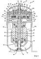
- Figure 1 is a cross-sectional view of a scroll compressor according to the present teachings
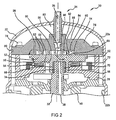
- Figure 2 is an enlarged fragmented view of a portion of the compressor of Figure 1 showing details of the fixed and orbiting scroll members;
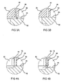
- Figures 3A and 3B are enlarged exemplary fragmented views of the interaction of the fixed and orbiting scroll members within circle 3 of Figure 2 in a non-sealed and sealed state according to the present teachings;
- Figures 4A and 4B are enlarged exemplary fragmented views of the interaction of the fixed and orbiting scroll members within circle 4 of Figure 2 in a sealed and non-sealed state according to the present teachings.
- Compressor 20 comprises a shell 22 having an upper portion 22a that is attached to a lower portion 22b in a sealed relationship.
- Shell 22 can be generally cylindrical.
- Upper shell 22a is provided with a refrigerant discharge port 24 through which a refrigerant discharge passage 26 extends.
- a stationary main bearing housing or body 28 and a lower bearing assembly 30 are secured in shell 22.
- a driveshaft or crankshaft 32 having an eccentric crankpin 34 at the upper end thereof is rotatably journaled in main bearing housing 28 and in lower bearing assembly 30.
- Crankshaft 32 has at the lower end a relatively large diameter concentric bore 36 which communicates with a radially outwardly inclined small diameter bore 38 extending upwardly therefrom to the top of crankshaft 32. Disposed within bore 36 is a stirrer 40.
- the lower portion of lower shell 22b forms a sump which is filled with lubricant and bore 36 can act as a pump to pump lubricating fluid up crankshaft 32 and into bore 38 and ultimately to various portions of the compressor that require lubrication.
- a strainer 42 is attached to the lower portion of shell 22b and directs the lubricant flow into bore 36.
- Crankshaft 32 is rotatably driven by an electric motor 44 disposed within lower bearing assembly 30.
- Electric motor 44 includes a stator 46, windings 48 passing therethrough, and a rotor 50 rigidly mounted on crankshaft 32.
- the upper surface of main bearing housing 28 includes a flat thrust-bearing surface 52 with an axially extending recess 54 therein.
- a floating seal 56 is disposed in recess 54.
- Thrust-bearing surface 52 and floating seal 56 axially support a lower surface 60 of an orbiting scroll member 62.
- Orbiting scroll member 62 includes a spiral vane or wrap 64 extending axially upwardly from an upper surface 65 thereof.
- Projecting downwardly from lower surface 60 of orbiting scroll member 62 is a cylindrical hub 66 having a journal bearing 68 and a drive bushing 70 therein and within which crankpin 34 is drivingly disposed.
- Crankpin 34 has a flat on one surface that drivingly engages a flat surface (not shown) formed in a portion of drive bushing 70 to provide a radially compliant drive arrangement, such as shown in Assignee's U.S. Patent No. 4,877,382 , entitled “Scroll-Type Machine with Axially Compliant Mounting," the disclosure of which is herein incorporated by reference.
- An Oldham coupling 72 can be positioned between and keyed to orbiting scroll member 62 and bearing housing 28 to prevent rotational movement of orbiting scroll member 62. Oldham coupling 72 may be of the type disclosed in the above-referenced U.S. Patent No.
- a non-orbiting scroll member 76 is stationarily secured within shell 22.
- Non-orbiting scroll member 76 can be secured to main bearing housing 28 with bolts 78.
- Main bearing housing 28 can provide axial support for the periphery of non-orbiting scroll member 76.
- a seal 80 can extend between upper shell 22a and the side of non-orbiting scroll member 76 to form a seal therebetween.
- a cavity 82 can be disposed above upper surface 84 of non-orbiting scroll member 76. Cavity 82 can be defined by upper surface 84 and upper shell 22a.
- Non-orbiting scroll member 76 includes opposite upper and lower surfaces 84, 86.
- Lower surface 86 includes a spiral vane or wrap 88 that extends axially downwardly and is in meshing engagement with wrap 64 of orbiting scroll member 62.
- Non-orbiting scroll member 76 has a centrally disposed discharge passage/port 90 that communicates with discharge passage 26 to direct compressed fluid out of scroll compressor 20.
- a discharge valve (not shown) may be disposed in discharge passage 90 and/or discharge passage 26. The discharge valve can be a one-way valve.
- Discharge passage 26 is disposed in discharge port 90 in a sealed manner that prevents fluid flowing through discharge port 90 and discharge passageway 26 from communicating with fluid in cavity 82 and can allow some relative axial motion between discharge passage 26 and non-orbiting scroll member 76.
- Orbiting scroll member 62 can orbit relative to non-orbiting scroll member 76 and cause the respective wraps 64, 88 to move relative to one another and form compression cavities/pockets 92 which progressively diminish in volume to compress the fluid therein.
- a plurality of compression cavities 92 is formed between wraps 64, 88.
- the fluid is sucked into the scroll set at a suction pressure adjacent the periphery of orbiting scroll member 62.
- the fluid is then compressed to the discharge pressure by the progressively diminishing size of compression cavities 92 and is discharged through discharge passage 90 in the center of non-orbiting scroll member 76.
- axial support for orbiting scroll member 62 is provided by floating seal 56 and thrust-bearing surface 52.
- Floating seal 56 and thrust-bearing surface 52 are located near the periphery of orbiting scroll member 62.
- orbiting scroll member 62 can experience bending such that upper surface 65 becomes concave (deformed downwardly in the view depicted in Figure 2 ), especially near the center.
- non-orbiting scroll member 76 is axially supported by bearing housing 28 adjacent the periphery and the higher pressure adjacent the center of non-orbiting scroll member 76 can cause lower surface 86 to also bend and become concave (deformed upwardly in the view depicted in Figure 2 ).
- the deflection of the central portion of orbiting scroll member 62 (downward in the view depicted in Figure 2 ) can be about 15-20 microns, relative to the periphery of orbiting scroll member 62, by way of non-limiting example.
- the deflection of the central portion of fixed scroll member 76 can be about 10-15 microns (upwards in the view depicted in Figure 2 ) relative to the periphery of fixed scroll member 76, by way of non-limiting example.
- the temperature of the compressed fluid also increases from the periphery toward the center of non-orbiting scroll member 76.
- the increasing temperature can cause wraps 64, 88 to experience thermal growth with the higher growth occurring in the centers of scroll members 62, 76 and lesser growth occurring around the periphery.
- Thermal growth may vary from about 0.5 microns on the scroll periphery to about 10 microns in the zone adjacent to the scroll center, by way of non-limiting example. Thermal growth of the wraps occurs in the direction away from the respective base plate.
- wrap 64 of orbiting scroll member 62 grows upwards (in the view depicted in Figure 2 ) from upper surface 65, while wrap 88 of non-orbiting scroll member 76 grows downwards (in the view depicted in Figure 2 ) from lower surface 86.
- fluid pressure in cavity 82 can be utilized to cause desirable bending or deformation of non-orbiting scroll member 76 to compensate for the undesirable deformation that can occur.
- the compensation can improve the sealing between the tips of wraps 64, 88 and the associated lower surface 86 of non-orbiting scroll member 76 and upper surface 65 of orbiting scroll member 62.
- this can be achieved by providing a high-pressure passageway 96 and a low-pressure passageway 98 that communicate with cavity 82 and extend through non-orbiting scroll member 76 to orbiting scroll member 62.
- high-pressure passageway 96 can be disposed adjacent discharge passage 90 and can extend through non-orbiting scroll member 76 from cavity 82 through wrap 88 adjacent discharge passage 90.
- Low-pressure passageway 98 can extend through non-orbiting scroll member 76 from cavity 82 through wrap 88 adjacent the periphery of orbiting scroll member 62.
- High-pressure passageway 96 and low-pressure passageway 98 can allow the fluid being compressed by compressor 20 to flow between the compression cavities 92 and cavity 82 in response to deformation of scroll members 62, 76 and compensate for the undesirable deformation, as described below.
- the inner diameter of passageways 96, 98 can be about one millimeter.
- high-pressure fluid in cavity 92 and discharge passage 90 adjacent wrap 88 containing high-pressure passageway 96 can travel through high-pressure passageway 96 and into cavity 82.
- the pressure in cavity 82 can increase up to a maximum of the discharge pressure of compressor 20 as fluid flows therein from high-pressure passageway 96.
- the increase in pressure in cavity 82 can cause the central portion of non-orbiting scroll member 76 to deform (downwardly in the views depicted) such that the wrap 88 through which high-pressure passageway 96 extends engages with upper surface 65 of orbiting scroll member 62, as shown in Figure 4A , and seals high-pressure passageway 96.
- low-pressure passageway 98 As the pressure in cavity 82 continues to decrease as the fluid flows through low-pressure passageway 98, the deformation of the central part of non-orbiting scroll member 76 can decrease and eventually result in low-pressure passageway 98 being sealed by the tips of the associated wrap 88 engaging with upper surface 65 of orbiting scroll member 62, as shown in Figure 3B . At that time, high-pressure passageway 96 may also still remain sealed, as shown in Figure 4A or possibly re-open as shown in Figure 4B .
- the high-pressure passageway 96 if not already re-opened, can again open due to separation between the wrap 88 associated with high-pressure passageway 96 disengaging from the upper surface 65 of orbiting scroll member 62 due to the fluid pressure therebetween and the thermal growth of wrap 88.
- fluid can flow from compression cavity 92 adjacent high-pressure passageway 96 and from discharge passage 90 into cavity 82 to again increase the pressure in cavity 82 and start the compensation cycle over again.
- the compensation cycle can continue to operate as compressor 20 is operated and the fluid being compressed therein causes axial deformation of the central parts of orbiting and non-orbiting scroll members 62, 76 and thermal growth of the associated wraps 64, 88.
- the pressure in cavity 82 will vary as high and low-pressure passageways 96, 98 are open and closed due to the compensation for the deformation.
- the cycling of the opening and closing of passageways 96, 98 can result in increased sealing between wraps 64, 88 such that an overall improvement in efficiency of compressor 20 is realized.
- non-orbiting scroll member 76 can influence the amount of deformation that occurs during operation of compressor 20 and, accordingly, can be selected such that their deformation is within an operational envelope wherein proper compensation can be achieved by altering the pressure in cavity 82 through the use of high and low-pressure passageways 96, 98.
- the pressure in cavity 82 can vary from discharge pressure to suction pressure depending upon the location of high and low-pressure passageways 96, 98 and the operational gaps between orbiting and non-orbiting scroll members 62, 76 at these locations through which passageways 96, 98 communicate with the working fluid.
- the location of axial supports for orbiting and non-orbiting scroll members 62, 76 can also affect the deformation that the scroll members incur. As such, the selection of the materials, dimensions, stiffness, location and quantity of supports, along with the number and size of high and low-pressure passageways 96, 98, can influence the ability of varying pressure in cavity 82 to compensate for deformations in orbiting and non-orbiting scroll members 62, 76.
- a scroll compressor with scroll deflection compensation can utilize high and low-pressure passageways 96, 98 that extend through non-orbiting scroll member 76 to allow fluid pressure in a cavity 82 that acts on the upper surface 84 of non-orbiting scroll member 76 to compensate for axial deformations and thermal growth of the associated wraps.
- the number, size, and location of high and low-pressure passageways 96, 98 can be chosen to provide a desired compensation.
- the dimensions and stiffness of scroll members 62, 76 and the location of axial supports therefore can also be chosen to work in conjunction with high and low-pressure passageways 96, 98 to allow the pressure in cavity 82 to compensate for the deformation and thermal growth.
- increased sealing contact between the tips of wraps 88, 64 and the associated upper and lower surfaces 65, 86 of the respective orbiting scroll member 62 and non-orbiting scroll member 76 can be improved thereby improving the overall efficiency of compressor 20.
- compressor 20 can take various forms and still be within the scope of the present teachings. Additionally, it should also be appreciated that the dimensions shown herein are for exemplary purposes only and may not reflect actual dimensions, relative or absolute, and, in some cases, may be exaggerated. Moreover, the location, number, and size of passageways 96, 98 are merely exemplary and changes in the location, size, and number can be employed without departing from the spirit and scope of the present teachings. It should be appreciated that it may be possible to include high and low pressure passageways that extend through orbiting scroll member 62 and communicate with a sealed cavity to allow orbiting scroll member 62 to compensate for the undesirable deformation.
Landscapes
- Engineering & Computer Science (AREA)
- Mechanical Engineering (AREA)
- General Engineering & Computer Science (AREA)
- Rotary Pumps (AREA)
- Applications Or Details Of Rotary Compressors (AREA)
Applications Claiming Priority (2)
| Application Number | Priority Date | Filing Date | Title |
|---|---|---|---|
| US97954307P | 2007-10-12 | 2007-10-12 | |
| US12/053,118 US7997883B2 (en) | 2007-10-12 | 2008-03-21 | Scroll compressor with scroll deflection compensation |
Publications (1)
| Publication Number | Publication Date |
|---|---|
| EP2048363A2 true EP2048363A2 (de) | 2009-04-15 |
Family
ID=40329100
Family Applications (1)
| Application Number | Title | Priority Date | Filing Date |
|---|---|---|---|
| EP08251207A Withdrawn EP2048363A2 (de) | 2007-10-12 | 2008-03-28 | Spiralverdichter mit Spiralablenkungskorrektur |
Country Status (6)
| Country | Link |
|---|---|
| US (1) | US7997883B2 (de) |
| EP (1) | EP2048363A2 (de) |
| CN (1) | CN101821511B (de) |
| AU (1) | AU2008312045C1 (de) |
| DE (1) | DE112008002715B4 (de) |
| WO (1) | WO2009051640A1 (de) |
Families Citing this family (9)
| Publication number | Priority date | Publication date | Assignee | Title |
|---|---|---|---|---|
| US20130177465A1 (en) * | 2012-01-06 | 2013-07-11 | Emerson Climate Technologies, Inc. | Compressor with compliant thrust bearing |
| US10094381B2 (en) * | 2015-06-05 | 2018-10-09 | Agilent Technologies, Inc. | Vacuum pump system with light gas pumping and leak detection apparatus comprising the same |
| KR20180136282A (ko) | 2017-06-14 | 2018-12-24 | 엘지전자 주식회사 | 원심 및 차압 급유 구조가 구비된 압축기 |
| KR101974272B1 (ko) | 2017-06-21 | 2019-04-30 | 엘지전자 주식회사 | 통합 유로 구조가 구비되는 압축기 |
| KR102396559B1 (ko) | 2017-06-22 | 2022-05-10 | 엘지전자 주식회사 | 스러스트면 윤활 구조가 구비된 압축기 |
| KR102440273B1 (ko) | 2017-06-23 | 2022-09-02 | 엘지전자 주식회사 | 토출 성능을 개선한 압축기 |
| KR102409675B1 (ko) | 2017-07-10 | 2022-06-15 | 엘지전자 주식회사 | 토출 구조를 개선한 압축기 |
| KR102383135B1 (ko) | 2017-07-24 | 2022-04-04 | 엘지전자 주식회사 | 원심 급유 구조가 구비된 압축기 |
| JP7166177B2 (ja) * | 2019-01-16 | 2022-11-07 | サンデン株式会社 | スクロール型流体機械 |
Citations (2)
| Publication number | Priority date | Publication date | Assignee | Title |
|---|---|---|---|---|
| US4877382A (en) | 1986-08-22 | 1989-10-31 | Copeland Corporation | Scroll-type machine with axially compliant mounting |
| US6231324B1 (en) | 2000-02-02 | 2001-05-15 | Copeland Corporation | Oldham coupling for scroll machine |
Family Cites Families (35)
| Publication number | Priority date | Publication date | Assignee | Title |
|---|---|---|---|---|
| JPS55148994A (en) * | 1979-05-09 | 1980-11-19 | Hitachi Ltd | Closed scroll fluid device |
| JPS6248979A (ja) * | 1985-08-27 | 1987-03-03 | Hitachi Ltd | スクロ−ル圧縮機 |
| US4600369A (en) * | 1985-09-11 | 1986-07-15 | Sundstrand Corporation | Positive displacement scroll type apparatus with fluid pressure biasing the scroll |
| JPH02305391A (ja) * | 1989-05-18 | 1990-12-18 | Hitachi Ltd | スクロール圧縮機 |
| US4993928A (en) * | 1989-10-10 | 1991-02-19 | Carrier Corporation | Scroll compressor with dual pocket axial compliance |
| US5145345A (en) * | 1989-12-18 | 1992-09-08 | Carrier Corporation | Magnetically actuated seal for scroll compressor |
| US5040956A (en) * | 1989-12-18 | 1991-08-20 | Carrier Corporation | Magnetically actuated seal for scroll compressor |
| US5085565A (en) * | 1990-09-24 | 1992-02-04 | Carrier Corporation | Axially compliant scroll with rotating pressure chambers |
| US5090878A (en) * | 1991-01-14 | 1992-02-25 | Carrier Corporation | Non-circular orbiting scroll for optimizing axial compliancy |
| US5256044A (en) * | 1991-09-23 | 1993-10-26 | Carrier Corporation | Scroll compressor with improved axial compliance |
| JP3127568B2 (ja) | 1992-05-08 | 2001-01-29 | ダイキン工業株式会社 | スクロール型流体装置 |
| US5277563A (en) * | 1992-08-10 | 1994-01-11 | Industrial Technology Research Institute | Scroll compressor with axial sealing apparatus |
| US5449279A (en) * | 1993-09-22 | 1995-09-12 | American Standard Inc. | Pressure biased co-rotational scroll apparatus with enhanced lubrication |
| TW316940B (de) * | 1994-09-16 | 1997-10-01 | Hitachi Ltd | |
| US5741120A (en) * | 1995-06-07 | 1998-04-21 | Copeland Corporation | Capacity modulated scroll machine |
| KR100387579B1 (ko) * | 1996-06-14 | 2003-09-19 | 엘지전자 주식회사 | 휴대단말기를이용한비디오시청장치 |
| JP3874469B2 (ja) * | 1996-10-04 | 2007-01-31 | 株式会社日立製作所 | スクロール圧縮機 |
| US5762483A (en) * | 1997-01-28 | 1998-06-09 | Carrier Corporation | Scroll compressor with controlled fluid venting to back pressure chamber |
| JPH11264386A (ja) * | 1998-03-19 | 1999-09-28 | Fujitsu General Ltd | スクロール圧縮機 |
| US6168404B1 (en) * | 1998-12-16 | 2001-01-02 | Tecumseh Products Company | Scroll compressor having axial compliance valve |
| JP3820824B2 (ja) * | 1999-12-06 | 2006-09-13 | ダイキン工業株式会社 | スクロール型圧縮機 |
| JP2002106482A (ja) * | 2000-09-29 | 2002-04-10 | Toyota Industries Corp | スクロール型圧縮機およびガス圧縮方法 |
| US6679683B2 (en) * | 2000-10-16 | 2004-01-20 | Copeland Corporation | Dual volume-ratio scroll machine |
| JP4288871B2 (ja) * | 2001-06-26 | 2009-07-01 | パナソニック電工株式会社 | 回転スイッチ |
| US6695599B2 (en) * | 2001-06-29 | 2004-02-24 | Nippon Soken, Inc. | Scroll compressor |
| KR20030012662A (ko) | 2001-08-03 | 2003-02-12 | 엘지전자 주식회사 | 스크롤 압축기의 마모 방지 구조 |
| US6554592B1 (en) * | 2001-10-16 | 2003-04-29 | Scroll Technologies | Scroll compressor with condition responsive back pressure chamber valve |
| JP3933492B2 (ja) * | 2002-02-19 | 2007-06-20 | サンデン株式会社 | スクロール型圧縮機 |
| US6896497B2 (en) * | 2003-07-31 | 2005-05-24 | Rechi Precision Co., Ltd. | Axial compliant means for a scroll machine |
| JP4156494B2 (ja) * | 2003-11-06 | 2008-09-24 | 株式会社デンソー | スクロール型圧縮機 |
| JP4514106B2 (ja) * | 2004-04-12 | 2010-07-28 | 日立アプライアンス株式会社 | スクロール圧縮機 |
| US7029251B2 (en) * | 2004-05-28 | 2006-04-18 | Rechi Precision Co., Ltd. | Backpressure mechanism of scroll type compressor |
| US7014434B2 (en) * | 2004-08-06 | 2006-03-21 | Anest Iwata Corporation | Scroll fluid machine |
| US7140851B2 (en) * | 2004-09-07 | 2006-11-28 | Chyn Tec. International Co., Ltd. | Axial compliance mechanism of scroll compressor |
| US6984115B1 (en) * | 2004-11-02 | 2006-01-10 | Chyn Tec. International Co., Ltd. | Axial sealing structure of scroll compressor |
-
2008
- 2008-03-21 US US12/053,118 patent/US7997883B2/en not_active Expired - Fee Related
- 2008-03-28 EP EP08251207A patent/EP2048363A2/de not_active Withdrawn
- 2008-09-29 WO PCT/US2008/011253 patent/WO2009051640A1/en active Application Filing
- 2008-09-29 AU AU2008312045A patent/AU2008312045C1/en not_active Ceased
- 2008-09-29 DE DE112008002715.3T patent/DE112008002715B4/de not_active Expired - Fee Related
- 2008-09-29 CN CN200880110664.6A patent/CN101821511B/zh not_active Expired - Fee Related
Patent Citations (2)
| Publication number | Priority date | Publication date | Assignee | Title |
|---|---|---|---|---|
| US4877382A (en) | 1986-08-22 | 1989-10-31 | Copeland Corporation | Scroll-type machine with axially compliant mounting |
| US6231324B1 (en) | 2000-02-02 | 2001-05-15 | Copeland Corporation | Oldham coupling for scroll machine |
Also Published As
| Publication number | Publication date |
|---|---|
| WO2009051640A1 (en) | 2009-04-23 |
| CN101821511A (zh) | 2010-09-01 |
| US7997883B2 (en) | 2011-08-16 |
| AU2008312045C1 (en) | 2012-08-30 |
| DE112008002715T5 (de) | 2010-11-11 |
| DE112008002715B4 (de) | 2014-02-06 |
| AU2008312045B2 (en) | 2012-02-23 |
| AU2008312045A1 (en) | 2009-04-23 |
| US20090098000A1 (en) | 2009-04-16 |
| CN101821511B (zh) | 2013-11-06 |
Similar Documents
| Publication | Publication Date | Title |
|---|---|---|
| AU2008312045B2 (en) | Scroll compressor with scroll deflection compensation | |
| US7771178B2 (en) | Vapor injection system for a scroll compressor | |
| EP1329636B1 (de) | Spiralverdichter mit Dampfeinspritzung | |
| KR100530662B1 (ko) | 스크롤형 유체 기계 | |
| EP1674846B1 (de) | Spiralmaschine mit Gegengewichten mit veränderlichem Hohlraum | |
| US6537043B1 (en) | Compressor discharge valve having a contoured body with a uniform thickness | |
| US7967584B2 (en) | Scroll machine using floating seal with backer | |
| US7914268B2 (en) | Compressor having shell with alignment features | |
| EP1260713B1 (de) | Spiralverdichter mit einer Oldham Kupplung | |
| EP1762727B1 (de) | Spiralmaschine mit Führungsbuchse | |
| EP1327779A1 (de) | Rotierender Flügelzellenkompressor mit Auslassventil | |
| EP1630421B1 (de) | Schmierpumpe eines Verdichters | |
| EP3415760B1 (de) | Spiralverdichter | |
| US6179591B1 (en) | Conical hub bearing for scroll machine | |
| AU2012203079B2 (en) | Counterweights for balancing rotary machines |
Legal Events
| Date | Code | Title | Description |
|---|---|---|---|
| PUAI | Public reference made under article 153(3) epc to a published international application that has entered the european phase |
Free format text: ORIGINAL CODE: 0009012 |
|
| AK | Designated contracting states |
Kind code of ref document: A2 Designated state(s): AT BE BG CH CY CZ DE DK EE ES FI FR GB GR HR HU IE IS IT LI LT LU LV MC MT NL NO PL PT RO SE SI SK TR |
|
| AX | Request for extension of the european patent |
Extension state: AL BA MK RS |
|
| STAA | Information on the status of an ep patent application or granted ep patent |
Free format text: STATUS: THE APPLICATION HAS BEEN WITHDRAWN |
|
| 18W | Application withdrawn |
Effective date: 20140521 |