EP2045966B1 - Überwachungssystem und -verfahren zur verbindung einer überwachungsvorrichtung mit einem dienstserver - Google Patents
Überwachungssystem und -verfahren zur verbindung einer überwachungsvorrichtung mit einem dienstserver Download PDFInfo
- Publication number
- EP2045966B1 EP2045966B1 EP09150846.5A EP09150846A EP2045966B1 EP 2045966 B1 EP2045966 B1 EP 2045966B1 EP 09150846 A EP09150846 A EP 09150846A EP 2045966 B1 EP2045966 B1 EP 2045966B1
- Authority
- EP
- European Patent Office
- Prior art keywords
- monitoring device
- server
- control server
- address
- service
- Prior art date
- Legal status (The legal status is an assumption and is not a legal conclusion. Google has not performed a legal analysis and makes no representation as to the accuracy of the status listed.)
- Active
Links
- 238000012806 monitoring device Methods 0.000 title claims abstract description 313
- 238000000034 method Methods 0.000 title claims abstract description 50
- 238000012544 monitoring process Methods 0.000 title description 60
- 230000004044 response Effects 0.000 claims abstract description 42
- 238000004891 communication Methods 0.000 claims abstract description 31
- 230000000977 initiatory effect Effects 0.000 claims description 25
- 230000009471 action Effects 0.000 claims description 3
- 230000008569 process Effects 0.000 description 26
- 238000012545 processing Methods 0.000 description 13
- 230000008901 benefit Effects 0.000 description 9
- 238000010586 diagram Methods 0.000 description 9
- 238000004519 manufacturing process Methods 0.000 description 8
- 230000006870 function Effects 0.000 description 7
- 238000009434 installation Methods 0.000 description 6
- 239000003795 chemical substances by application Substances 0.000 description 3
- 238000013519 translation Methods 0.000 description 3
- 239000000284 extract Substances 0.000 description 2
- 230000002093 peripheral effect Effects 0.000 description 2
- 230000011664 signaling Effects 0.000 description 2
- 238000012360 testing method Methods 0.000 description 2
- FGRBYDKOBBBPOI-UHFFFAOYSA-N 10,10-dioxo-2-[4-(N-phenylanilino)phenyl]thioxanthen-9-one Chemical compound O=C1c2ccccc2S(=O)(=O)c2ccc(cc12)-c1ccc(cc1)N(c1ccccc1)c1ccccc1 FGRBYDKOBBBPOI-UHFFFAOYSA-N 0.000 description 1
- 238000013475 authorization Methods 0.000 description 1
- 230000008859 change Effects 0.000 description 1
- 230000001419 dependent effect Effects 0.000 description 1
- 238000005516 engineering process Methods 0.000 description 1
- 238000000605 extraction Methods 0.000 description 1
- 230000008571 general function Effects 0.000 description 1
- 230000010354 integration Effects 0.000 description 1
- 230000003993 interaction Effects 0.000 description 1
- 238000012423 maintenance Methods 0.000 description 1
- 239000003550 marker Substances 0.000 description 1
- 238000012986 modification Methods 0.000 description 1
- 230000004048 modification Effects 0.000 description 1
- 230000008520 organization Effects 0.000 description 1
- 238000012546 transfer Methods 0.000 description 1
Images


Classifications
-
- H—ELECTRICITY
- H04—ELECTRIC COMMUNICATION TECHNIQUE
- H04L—TRANSMISSION OF DIGITAL INFORMATION, e.g. TELEGRAPHIC COMMUNICATION
- H04L61/00—Network arrangements, protocols or services for addressing or naming
- H04L61/50—Address allocation
- H04L61/5007—Internet protocol [IP] addresses
- H04L61/5014—Internet protocol [IP] addresses using dynamic host configuration protocol [DHCP] or bootstrap protocol [BOOTP]
-
- H—ELECTRICITY
- H04—ELECTRIC COMMUNICATION TECHNIQUE
- H04L—TRANSMISSION OF DIGITAL INFORMATION, e.g. TELEGRAPHIC COMMUNICATION
- H04L41/00—Arrangements for maintenance, administration or management of data switching networks, e.g. of packet switching networks
- H04L41/08—Configuration management of networks or network elements
- H04L41/0803—Configuration setting
- H04L41/0806—Configuration setting for initial configuration or provisioning, e.g. plug-and-play
- H04L41/0809—Plug-and-play configuration
-
- H—ELECTRICITY
- H04—ELECTRIC COMMUNICATION TECHNIQUE
- H04L—TRANSMISSION OF DIGITAL INFORMATION, e.g. TELEGRAPHIC COMMUNICATION
- H04L41/00—Arrangements for maintenance, administration or management of data switching networks, e.g. of packet switching networks
- H04L41/34—Signalling channels for network management communication
-
- H—ELECTRICITY
- H04—ELECTRIC COMMUNICATION TECHNIQUE
- H04L—TRANSMISSION OF DIGITAL INFORMATION, e.g. TELEGRAPHIC COMMUNICATION
- H04L61/00—Network arrangements, protocols or services for addressing or naming
-
- H—ELECTRICITY
- H04—ELECTRIC COMMUNICATION TECHNIQUE
- H04L—TRANSMISSION OF DIGITAL INFORMATION, e.g. TELEGRAPHIC COMMUNICATION
- H04L65/00—Network arrangements, protocols or services for supporting real-time applications in data packet communication
- H04L65/40—Support for services or applications
-
- H—ELECTRICITY
- H04—ELECTRIC COMMUNICATION TECHNIQUE
- H04L—TRANSMISSION OF DIGITAL INFORMATION, e.g. TELEGRAPHIC COMMUNICATION
- H04L67/00—Network arrangements or protocols for supporting network services or applications
- H04L67/01—Protocols
- H04L67/02—Protocols based on web technology, e.g. hypertext transfer protocol [HTTP]
- H04L67/025—Protocols based on web technology, e.g. hypertext transfer protocol [HTTP] for remote control or remote monitoring of applications
-
- H—ELECTRICITY
- H04—ELECTRIC COMMUNICATION TECHNIQUE
- H04L—TRANSMISSION OF DIGITAL INFORMATION, e.g. TELEGRAPHIC COMMUNICATION
- H04L67/00—Network arrangements or protocols for supporting network services or applications
- H04L67/01—Protocols
- H04L67/12—Protocols specially adapted for proprietary or special-purpose networking environments, e.g. medical networks, sensor networks, networks in vehicles or remote metering networks
- H04L67/125—Protocols specially adapted for proprietary or special-purpose networking environments, e.g. medical networks, sensor networks, networks in vehicles or remote metering networks involving control of end-device applications over a network
-
- H—ELECTRICITY
- H04—ELECTRIC COMMUNICATION TECHNIQUE
- H04L—TRANSMISSION OF DIGITAL INFORMATION, e.g. TELEGRAPHIC COMMUNICATION
- H04L67/00—Network arrangements or protocols for supporting network services or applications
- H04L67/50—Network services
- H04L67/51—Discovery or management thereof, e.g. service location protocol [SLP] or web services
-
- H—ELECTRICITY
- H04—ELECTRIC COMMUNICATION TECHNIQUE
- H04L—TRANSMISSION OF DIGITAL INFORMATION, e.g. TELEGRAPHIC COMMUNICATION
- H04L41/00—Arrangements for maintenance, administration or management of data switching networks, e.g. of packet switching networks
- H04L41/08—Configuration management of networks or network elements
- H04L41/085—Retrieval of network configuration; Tracking network configuration history
- H04L41/0853—Retrieval of network configuration; Tracking network configuration history by actively collecting configuration information or by backing up configuration information
- H04L41/0856—Retrieval of network configuration; Tracking network configuration history by actively collecting configuration information or by backing up configuration information by backing up or archiving configuration information
-
- H—ELECTRICITY
- H04—ELECTRIC COMMUNICATION TECHNIQUE
- H04L—TRANSMISSION OF DIGITAL INFORMATION, e.g. TELEGRAPHIC COMMUNICATION
- H04L63/00—Network architectures or network communication protocols for network security
- H04L63/08—Network architectures or network communication protocols for network security for authentication of entities
Definitions
- the present invention relates to monitoring systems and devices of such a system.
- the invention relates to a method for customizing a monitoring device.
- Monitoring systems for monitoring of premises, areas of particular interest and/or processes connected via a computer network to monitoring or surveillance servers are increasingly popular, in particular such monitoring systems including digital monitoring cameras.
- One reason for the popularity of such systems may be that the systems in great extent may utilize an existing network, if a computer network already is in place.
- Another reason for using a general computer network as a surveillance network may be that the network that has to be built for the monitoring system may be used to connect other types of equipment, e.g. computers, servers and peripherals.
- the technology suits organizations/persons in need of only a single or few monitoring devices as well as organizations/persons in need of a great number of monitoring devices.
- the monitoring devices are arranged to send their monitoring data to a service server which processed the monitoring data or information in order to prepare the data for access by a user, for logging monitoring information, for storing, or for other purposes known to a person skilled in the art of monitoring systems.
- the monitoring devices of such system are manufactured by one company and the service server is maintained by a monitoring service provider, being another company.
- the monitoring service provider may be a company or organization specialized in providing such services.
- the monitoring service provider may, however, also be a company related to the monitored premises, areas and/or processes, i.e. the company owning or operating at the monitored sites.
- each monitoring device may be provided with the address to a service server by the user keying the address directly into the monitoring device.
- Another method for achieving a connection between the monitoring device and a service server is to connect to the service server via a computer connected to the computer network and register the monitoring device at the service server.
- Some general problems associated with the above described monitoring systems are that the person performing the installation may not be experienced in programming monitoring devices, the programming may be time consuming, and/or the person may enter erroneous data into the monitoring device.
- WO 03/055248 a process for remote managing of a device is described.
- the Process begins with a step in which a remotely managed device is activated.
- the device runs a management agent, which transmits a registration event message to a management server.
- the registration event message includes information identifying the device and information relating to the state of the device.
- the management server registers the device by storing registration information relating to the device in a management data.
- the registration information includes the identity and the state of the device.
- the management server places commands intended for remotely managed the device in a Device Control Box (DCB).
- DCB Device Control Box
- Such a command may be reconfiguring applications that may run on the remotely managed device.
- the commands stored in the DCB are delivered to the remotely managed device.
- a connection is established between the management agent, running on the remotely managed device, and the management server. Upon the connection being established, the commands that were stored in the DCB are transmitted to the device.
- the management agent executes the retrieved commands.
- One object of the present invention is to provide an improved monitoring system.
- a method for customizing a monitoring device comprises sending a connection message from the monitoring device to a control server, receiving the connection message at the control server, extracting at the control server an identity code from communication between the monitoring device and the control server, said identity code uniquely identifying the monitoring device, matching the identity code to a program code at the control server, generating at the control server a reconfiguration message including the program code, sending from the control server to the monitoring device the reconfiguration message, receiving the reconfiguring message at the monitoring device, and changing program code stored in the monitoring device to program code of the reconfiguring message.
- connection message is sent in response to an initiation action.
- the method further comprises executing the changed program code received in the reconfiguration message on the monitoring device.
- the reconfiguration message additionally include data for changing the properties of the monitoring device.
- the reconfiguration message including program code is generated by the control server in response to the connection message from the monitoring device being the first connection message.
- the matching of the identity code to a program is performed by matching the identity code to a service provider and then identifying program code associated with the service provider.
- a method for connecting a monitoring device to a service server comprises retrieving an address relating to a control server from a memory of the monitoring device, sending a connection message from the monitoring device to the address relating to a control server in response to a connecting event, extracting, at the control server, an identifier from the communication between the monitoring device and the control server, identifying, at the control server, a service server associated with the extracted identifier, sending an address relating to the identified service server from the control server to the monitoring device, sending a connection message from the monitoring device to the identified service server in response to the receipt of the address related to the identified service server, establishing a service connection between the monitoring device and the identified server.
- the monitoring system comprises a monitoring device, a control server, a plurality of service servers and a network connecting the servers and the monitoring device.
- the monitoring device includes a memory including a connection address initiating means arranged to send a connection message over the network to the connection address in response to an initiation event, and means arranged to send a new connection message to an address received in a message via said network.
- the control server includes an identity extractor arranged to extract an identifier from a communication between the monitoring device and the control server, matching means arranged to match the extracted identifier to a control server or a service server and retrieve an address to the matched service server, and a message generator arranged to generate a message including the retrieved address and to send the generated message to the monitoring device.
- Each service server includes means for receiving and processing monitoring data from a monitoring device.
- An advantage with the above described method and system is that the maintenance and installation of the device may be facilitated because of the monitoring device being guided to a preferred service server by a control server instead of requiring a person to key in the address to a preferred service server. Additionally, in this way the system may be more efficiently maintained, because the control server may be easier or more effective to keep updated with new or changing service server addresses than the user or the person maintaining the monitoring device.
- a further advantage is that the monitoring device initiate all connections with the control server/servers and the service server/servers, which facilitate the integration of monitoring devices from behind access limiting devices, e.g. a firewall, a NAT (Network Address Translation), an ISP (Internet Service Provider) providing dynamic addresses, into a system reaching outside such access limiting devices.
- access limiting devices e.g. a firewall, a NAT (Network Address Translation), an ISP (Internet Service Provider) providing dynamic addresses, into a system reaching outside such access limiting devices.
- an initial retrieval of an address relating to a control server from a memory of the monitoring device in the above mentioned method returns a preconfigured address relating to a control server and wherein an initial sending of a connection message from the monitoring device to the preconfigured address is performed in response to an initiation event of the monitoring device.
- the advantage of arranging an initial control server like this is that the installation and customization of monitoring devices of the system is facilitated.
- the installation is facilitated as a result of the initiation of the monitoring device automatically contacts a predetermined control server upon initiation of the monitoring device, thus no need to provide any addresses to the monitoring device during installation.
- the customization is facilitated because specific properties relating to the monitoring device may be provided by the control server upon initial communication between the monitoring device and the control server, i.e. the initial control server. Accordingly, the manufacturer of the monitoring device do not need to have different manufacturing processes for different batches of monitoring devices.
- the system according to this embodiment of the invention may solve problems of the manufacturer relating to customization of devices.
- the monitoring devices of the monitoring systems of today has to be associated with different service providers and then each device associated with a service provider has to be programmed in a process that is customized for the associated service provider.
- the manufacturer has to provide a plurality of different manufacturing processes for devices intended for different service providers. More over the devices so programmed for a specific service provider has to be delivered and sold to the specific service provider or costumers of the specific service provider.
- Another advantage of this embodiment is that it enables central management of monitoring devices and for all service servers.
- the sending of a connection message from the monitoring device to a control server is performed at least one time prior to sending a connection message from the monitoring device to a control server which provides an address of a service server to the monitoring device.
- the advantage of arranging a plurality of control servers and directing a monitoring device to another control server is that the responsibility of directing the monitoring device to a correct service server may be changed from an entity responsible of the general functionality of the system, e.g. the manufacturer of the monitoring device, to an entity responsible for providing the required service, e.g. the service provider.
- the act of identifying a service server further includes the acts of extracting a network address relating to the monitoring device from the communication between the monitoring device and the control server, matching the network address to a service provider, and selecting a service server associated with the matched service provider.
- the network address relating to the monitoring device in this way it may be easy to identify the service provider, at least in those cases the service provider providing the network connection is associated to a provider of a monitoring service or if those service providers are the same.
- the act of identifying a service server further includes the acts of extracting an identification code included by the monitoring device in the communication between the monitoring device and the control server, matching said identification code to a service provider, and selecting a service server associated with the matched service provider.
- the monitoring devices may be customized and connected to a specific monitoring service provider based on various criteria. For instance a batch of monitoring devices may be dedicated to a specific monitoring service provider offering a discount when buying the monitoring device with the reservation that the device will be connected to service servers of that monitoring service provider. Thus, the service provider is able to ensure the connection of the monitoring device to the services of the service provider. Further, the batch of monitoring devices may be dedicated to a company having a service server of their own for the monitoring of their own premises.
- the monitoring device sends the connection message to the control server or to the service server.
- the servers may be arranged to send control messages in the responses to the messages from the monitoring device, e.g. in the response to a http request.
- the control server may exercise control over the monitoring device despite possible access hindering devices, e.g. firewalls, NAT servers, etc., arranged between the monitoring device and the server
- the system includes a plurality of control servers including at least one initial control server, being a high level, or even a top level, control server in an hierarchy of control servers.
- Such initial control server is arranged to access address information enabling at least indirect connection to any control server and service server in the system.
- the initial control server may be given an overall responsibility of directing a monitoring device to the correct subsystem of control servers and service servers, while a control server in such a subsystem may be given the responsibility to directing the monitoring device to the most suitable service server.
- the monitoring system 10 includes a monitoring device 20, a control server 30 and a service server 40.
- the monitoring device 20, the control server 30, and the service server 40 are connected to each other via a computer network 50, such as Internet, a LAN (Local Area Network), a WAN, (Wide Area Network).
- the computer network 50 may include wireless and/or wired communication channels.
- the monitoring device 20 may be a digital camera, a motion detector, an audio detector, an IR-detector, a passage control device, an electronic door lock, an elevator control system, a card reader, etc.
- the monitoring device 20 is arranged to send a connection message 600 in response to an initiation action or an initiation event to an address stored within the monitoring device 20.
- the connection message is received at a control server 30 residing at said address.
- the control server 30 receives the connection message and the monitoring device 20 and the control server 30 establish a connection.
- the control server also extracts an identifier from the communication received from the monitoring device 20. The identifier is used to match the monitoring device to a preferred service provider and a service server.
- control server 30 When the control server 30 has found a match it sends an address in a message 602 to the monitoring device.
- the message is identified as a change of address message or a reconfiguration message at the monitoring device 20.
- the monitoring device 20 stores the new address and sends a connection message 600 or 604 to the new address.
- the address received from the control server 30 may address another control server 30 or a service server 30 depending on the structure of the system, this will be explained below.
- the service server 40 and the monitoring device 20 then establish a service connection 606 enabling communication of monitoring data to the service server 40 and possibly, but not necessary, configuration parameters to the monitoring device.
- the monitoring device 20 has been connected to a server that is enable to provide the monitoring services.
- the service server 40 to which the monitoring device 20 has been directed may then be the most suitable service server 40 in regard of geographic location, location in the network, available services, and/or customer specific reasons. Which of these criteria that is applicable in regard of specific monitoring devices 20 may be controlled by the data provided to the control server 30 or control servers 30 directing the monitoring device 20 to the service server 40.
- the monitoring device 20 may include an input means 202, a processing means 204, a non volatile memory 206, a volatile memory 208, a network interface 210, an initiation means 212, an a monitoring device means 216 as shown in Fig 3a and in Fig 3b.
- Fig 3a is a schematic view of a general monitoring device
- Fig 3b is a schematic view of a monitoring device 20 being a digital camera.
- the figures 3a and 3b do not show all means needed to make the device perform its normal functions, i.e. the means that makes an IR detector function as an IR detector or that makes a digital camera function as a digital camera.
- All means, such as hardware and software, required to make the monitoring device work as a monitoring device is indicated by the monitoring device means 216 in Fig 3a .
- the corresponding means of the camera is referred to as video camera means 218.
- the means and arrangements required for making an ordinary monitoring device network enabled are known to a skilled person.
- An example of such network enabled monitoring devices on the market today are the networked digital cameras from Axis Communications AB, Emdalavägen 14, S-223 69 Lund, Sweden.
- the monitoring device 20 may be any type of a plurality of types of devices and the input means 202 of the monitoring device 20 is different in different types of monitoring devices.
- the input means 202 of the digital camera 20a in Fig 3b may be an image sensor, e.g. a CCD, the input means of an audio detector may be a microphone, etc.
- the main function of the input means 202 is to detect, sample or measure the properties monitored by the monitoring device 20 and provide such data to the processing means 204 for further processing.
- the processing means 204 is arranged to control the functionality of the monitoring device and execute program code related to the functions of the present invention and general functions of the monitoring device 20.
- the non volatile memory 206 may be used by the monitoring device 20 for storing data and information relating to the functionality of the monitoring device and its interaction with the monitoring system.
- a list 214 of addresses to severs on the network is stored in the non volatile memory.
- the list 214 of addresses may be prioritized by marking each address entry with a priority marker. The markers may be numbers identifying the priority.
- the list 214 of addresses in a monitoring device shipped from the manufacturer includes at least one preprogrammed address to a control server 30, this server is generally referred to as initial control server in this application.
- the list 214 may include a plurality of addresses wherein the address marked as having the highest priority is the first address the monitoring device will send a connection message to in response to a connection event.
- the next address in the prioritized list is tried and a connection message is sent to that one as well.
- the next address tried in the list 214 in case of the first address failing, is randomly selected, which may result in load distribution in the network in case of many devices are equipped with identical lists and try to connect to a faulty address essentially simultaneously.
- the volatile memory 208 may be used to support the processing means 204 and/or to temporarily store addresses received from servers. Accordingly, the volatile memory 208 may also be a memory used by the applications executed on the monitoring device 20 by the processing means 204.
- the network interface 210 is the interface between the monitoring device 20 and the network 50.
- Hardware and software for a number of different networks that may be used to implement the network interface 210 are well known by the person skilled in the art of computer networks.
- the initiation means 212 is a means generating an initiation event and thereby triggering the sending of the initial connection message to the prioritized address stored in the non volatile memory 206.
- the initiation means 212 is a detector enabled to detect the connection of the monitoring device 20 to a network 50, i.e. either the connecting of a powered monitoring device 20 to a network 50 or the powering up of a monitoring device 20 already physically connected to a network 20. By arranging such an initiation means 212 the searching and connecting to a suitable service server 40 may be fully automated.
- the initiation means 212 may be a power on button of the monitoring device 20 or it may be a button dedicated for the initiation of the connecting of the monitoring device 20 to a service server 40.
- Means arranged to send a connection message to a control server 30 or a service server 40 in response to a message including an address to such a server or a reconfiguration message including an address to such a server may be implemented by program code executed by the processing means 204.
- the process of the monitoring device 20 finding a service server 40 is illustrated in Fig 4 .
- the monitoring device 20 which is either offline or shut off, is initiated, i.e. connected to the network, powered up, or initiated in any other way described above, step 620.
- the monitoring device 20 then retrieves the first address from the prioritized list in the non volatile memory 206, step 622.
- This address may be the address stored by the manufacturer during the manufacturing process. However, if the monitoring device 20 has been previously connected to a system according to the invention the address may be an address stored in response to a reconfiguration message or another message including an address to a more suitable server than the server of the address initially provided in the monitoring device 20.
- the monitoring device sends a connection message via the network interface 210 to a server associated with the retrieved address, step 624.
- the monitoring device waits for a response from the server that received the connection message.
- the monitoring device stores this address in the non volatile memory 206, step 628.
- the address may be stored as the most prioritized in the list 214.
- the response message or reconfiguration message from the server may, according to one specific embodiment, include an entirely new list of server addresses replacing the present list in the non volatile memory 206 or a subset of addresses substituting some of the addresses in the present list.
- the monitoring device sends a new connection message, step 630, to the new server address, or the first address in the prioritized list after the list has been changed in step 628, in response to the received message. Then the monitoring device 20 once more waits for a response from the server to which the connection message was sent.
- step 626 the monitoring device 20 check if the response includes an indication of the server being a service server 40 in itself, step 632. If the response includes such an indication the monitoring device 20 and the service server establish a service connection, step 634.
- the monitoring device may wait for another message from the server.
- the monitoring device sends a connection message to another address in the list directly when a response message is determined not to identify the server as a service server or not to identify a new server address.
- such a connection message is sent to another address in the list after a counter or timer indicate that the server or the address is likely to be erroneous.
- Said another address may be the next address in a prioritized list or a random selection in the list, as described earlier.
- the step 622 of retrieving a server address from the non volatile memory monitoring device additionally includes retrieving an identity code being an identifier uniquely identifying the monitoring device, e.g. such as a serial number, a product code combined with an item specific code, etc. This identifier is then sent, step 625, to the server of the retrieved address either in the connection message, step 624, or in a later communication with the server.
- an identity code being an identifier uniquely identifying the monitoring device, e.g. such as a serial number, a product code combined with an item specific code, etc.
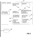
- control server 30 In Fig 5 one embodiment of the control server 30 is schematically illustrated. In the system the control server 30 or control servers 30 may be seen as guides or switchboards.
- the automatic connection set up by the monitoring device 20 is analyzed in the control server and the control server 30 provide the monitoring device 20 with an address to a new server, being the most relevant based on the information of other servers available to the control server 30 and the information provided in the communication with the monitoring device 20.
- the control server 30 includes a network interface 310 in order to provide network communications, a processing means 312 for operation of the control server 30, a memory 314 for supporting and storing application programs executed by the processing means 312, an identity extractor 316 for extracting an identifier of a monitoring device from the communication between the monitoring device 20 and the control server 30, matching means 318 for matching the identifier to a server and a reconfiguration message generator 320 for generating and sending an address associated to a server matched to the extracted identifier.
- the identity extractor 316 may be arranged to extract an identifier from the communication between the control server 30 and a monitoring device by extracting the address of the monitoring device connecting to the control server 30, the address may for instance be the IP-address of the monitoring device 20. This extraction is performed by an IP-address 322 extractor which may be arranged to pinpoint the response address included in the message originating from the monitoring device 20.
- the identity extractor 316 includes an identity code extractor 324 arranged to extract an identity code sent by the monitoring device 20 in the communication between the control server 30 and the monitoring device 20.
- the control server 30 includes both the IP-address extractor 322 and the identity code extractor 324 and may use them in accordance with different schemes, e.g.
- the identity extractor may start to extract and test if the IP-address is associated to a server in a database 330 and if not continue with a identity code check or the identity extractor may be arranged to start to extract and test the identity code and then the IP-address.
- the matching means 318 makes use of the identifier extracted by the identity extractor 316 to find the most suitable server for the monitoring device.
- the matching means 318 is arranged to match the identifier of the monitoring device to a server by accessing a list or database 330 of identifiers and associated servers.
- the access of the list or database is performed by means of a data base access means 326.
- the list or database 330 used for matching may be arranged in the server, as a peripheral to the server, or it may be arranged for access via the network, the later embodiment is depicted in Fig 5 .
- the list or database 330 may, according to one embodiment, include entries of identifiers and each identifier being associated with at least one control server or service server. Additional arrangements of the list or database 330 is known to the skilled person.
- the database 330 or list including the entries of identifiers and information associating an identifier of a monitoring device to a control server or a service server may be edited by accessing the list or database 330.
- the database 330 or the list may require authorization in order to allow someone to edit. Such editing of the list or database 330 may be performed in many different ways.
- the editing may be performed in connection with the production of the monitoring device, in such case the identity code of the monitoring device is entered and associated with a predetermined service provider or server of a service provider, the editing may be performed by the service provider entering an identity code of a monitoring device that are to be associated to one or a set of their servers, the editing may be performed by the service provider entering IP addresses of their network and associates these to one of or a set of their servers, etc.
- the control server 30 receives a connection message from a monitoring device 20, step 710, via the network and the network interface 310.
- the monitoring device 20 and the control server 30 establishes a connection for communication, step 712.
- the identity extractor 316 of the control sever 30 extracts the identifier from the communication, step 714.
- the identifier is then processed by the matching means 318, which matches the identifier to, in this particular embodiment, a service provider, step 716.
- control server 30 may generate an error message, step 720, and return this message to the monitoring device 20 in a response to the connection message.
- the monitoring device 20 may be arranged to display a specific error code or activate some LED, Light Emitting Diode, indicating the type of error.
- the user may inform the support of the monitoring device or the service provider, depending on which of the parties who is to provide support, and they may enter a correct address associated to the monitoring device 20 or the IP address of the monitoring device 20, enter the identifier of the monitoring device in the database and associate it to a server, etc.
- step 718 a service provider is matched to the identifier then the matching means 318 retrieves an address to a server of that service provider, step 722.
- the retrieved server address is then presented to the reconfiguration message generator 320, which generates a reconfiguration message or another type of message, step 724, including the retrieved server address. Then the reconfiguring message is sent, step 726, to the monitoring device 20 and the monitoring device acts on the reconfiguring message as described above in connection with Figs 3-4 .
- the process described in Fig 6a may advantageously be implemented in an initial control server, i.e. the type of control server addressed by the addresses arranged in the monitoring device in connection with manufacturing of the monitoring device.
- a control server may be controlled by the manufacturer of the monitoring device and may present the benefit of making it possible for the manufacturer to configure large series of monitoring devices using identical processes, programs and properties, independent of who will buy the device or which service provider that are to be related to the monitoring device.
- the programs and properties of monitoring devices may be automatically changed when connecting to the control server 30 for the first time in order to customize in accordance with specific requests from service providers or other parties related to the device. Such automatic changes are delivered to the monitoring device 20 in a reconfiguration message.
- FIG. 6b Another embodiment of the process of a control server may be as showed in Fig 6b , the process is similar to the process of the embodiment in Fig 6a and therefore the same reference numerals are used for the steps that are identical with the process of Fig 6a .
- the steps that differs also uses the same reference numerals, but are marked with a the symbol' after the number. Accordingly, the differences are generally that the process of Fig 6b does not match a server by first matching a service provider, but the server is directly matched to the identifier. Accordingly, the extracted identifier is matched to a server in the data base, step 718', and if a server is found, step 718', the server address associated with the matched server is retrieved, step 722'. The rest of the process is identical to the process in Fig 6a .
- a control server 30 like the one described in connection with Figs 5 , 6a and 6b may be used as an initial control server 30. Additionally, such a control server 30 may be useful as a later stage control server 30, i.e. a control server 30 arranged in a subsystem or a control server 30 of a service provider that the initial control server 30 may provide the address to if not all the service server addresses of a service provider are stored in the database 330 utilized by the initial control server 30. In this way different parties may manage different sets of servers in accordance with their objectives.
- the manufacturer of the monitoring devices manages a set of initial control servers and the service providers manages service servers and possibly some control servers
- the manufacturer only is required to keep track of the service providers and a subset of the servers of the service providers, while the service providers are allowed to set up their service servers as they wish without having to consider changes to the database and control server of the manufacturer.
- the service server 40 in the system may be seen as a server providing a user interface between the monitoring device 20 and the user.
- the service server 40 is arranged to provide a service connection to the monitoring device for transfer of the monitoring data to the service server. Additionally, the service server may be arranged to process the data received from the monitoring device 20 in order to present it or make it possible for a client of a user to present.
- the service server 40 may also be arranged to control the monitoring device. In order to accomplish sending of control parameters, data, updates, etc., even to monitoring devices arranged behind access limiting devices, e.g. a firewall, a NAT (Network Address Translation), an ISP (Internet Service Provider) providing dynamic addresses, the service server 40 may be arranged to send such information in responses to requests sent from the monitoring device. This, is easily accomplished as the monitoring device 20 is arranged to initiate the communications.
- the service server includes a network interface 410 for enabling communication with monitoring devices over the network 50, processing means 412 for execution of applications on the service server, a memory 414 to store applications and data, and a monitoring data presentation means 416.
- the monitoring data presentation means 416 comprises one or a plurality of applications for enabling presentation of monitoring data from one or a plurality of monitoring devices.
- Service servers providing the possibility to receive monitoring data, process the data and present the data for users are known to persons skilled in the art.
- An example of an possible service server 40 is found in the Swedish patent application 0500071-6 with the title "Monitoring system and method for accessing a monitoring device of a monitoring system". This application also describes a method for communicating through access limiting devices.
- the service server 40 receives a connection message from a monitoring device 20, step 810. Then the service server and the monitoring device establishes a service connection, step 812. When the service connection is established the service server 40 may start receiving monitoring data from the monitoring device, step 814, and processing, step 816, the received monitoring data in accordance with the requirements of the service server 40 or the desires of the final user. Then the service server 40 may store the monitoring data, step 818, for presentation for a client of a user or for download to a client or a server of the user.
- a client may be a workstation computer, a desktop computer, a laptop computer, a handheld computer, e.g. a PDA (Personal digital Assistant), a mobile telephone, etc.
- the system for connecting a monitoring device to a service server may include a plurality of monitoring devices 20, a plurality of control servers and a plurality of service servers.
- the monitoring devices may be connected to the network 50 directly, via another network, via an access limiting device, etc.
- Fig. 9 one example of a system including three monitoring devices 20-22 and two service servers 40-41.
- two of the monitoring devices are depicted as monitoring cameras, by using two visually differently looking figures of cameras and one general box indicating a monitoring device we want to emphasize that the monitoring devices in the system are not necessarily identical in regard of brand, type or even monitoring function, i.e. the monitoring system may include an IR detector, a wide angle camera, a low resolution camera, simultaneously.
- the numbers of monitoring devices 20-22 in the example illustrated by Fig 9 may easily be increased as well as the number of service servers 40-41.
- the example system includes one control server 30, which may be a manufacturer controlled control server.
- one of the monitoring devices 22 is connected to the network via a access limiting device 60, e.g. a firewall, a NAT (Network Address Translation) server, an ISP (Internet Service Provider) providing dynamic addresses, firewall.
- a access limiting device 60 e.g. a firewall, a NAT (Network Address Translation) server, an ISP (Internet Service Provider) providing dynamic addresses, firewall.
- Such an access limiting device are not limiting the access of the monitoring device from the servers because they are arranged to send information or instructions to monitoring devices in a way passing through such devices, e.g. by means of providing the information or instructions in responses to messages or requests from the monitoring device.
- the database accessed by the control server 30 during the process of matching each of the monitoring devices to a server may include information associating the IP-address of the monitoring device 20 to the service server 40, based on the fact that the IP-address of monitoring device 20 is an IP-address of a internet access provider providing the service server 40. Additionally or alternatively, the database may include information associating an identity code sent from each of the monitoring devices 21 and 22 with the service server 41. Accordingly, the control server 30 may send the address of service server 40 to monitoring device 20 and the address of service server 41 to monitoring devices 21 and 22 in response to the connection messages sent by each of the monitoring devices, if the database of the control server include information associating the monitoring devices 20-22 to those service servers.
- the addresses received at the monitoring devices may be stored in non volatile memory in order to be used during a future initiation. For example if monitoring device 20 is disconnected and reconnected again the address of service server 40 may be stored in non volatile memory and the monitoring device may send the connection message directly to service server 40 instead of sending it to the control server 30.
- Fig 10 yet another possible configuration is presented.
- the control server may be an initial control server. In this way the installation of the cameras are greatly simplified because the monitoring devices 20 only have to be mounted and connected to the private network 51 then the monitoring devices 20 automatically finds and reconfigures to connect to the intended service server 40 by means of the control server 30.
- a monitoring service provider also is a provider of services such as network access, i.e. internet access.
- An IP-address, a portion of an IP-address, or a plurality of IP-addresses are stored in the database related to the control server 30 of the manufacturer, i.e. as much info of the IP-address or as many IP-addresses that is needed for identifying a monitoring device as being connected to a IP-address of the service provider is loaded into the database of the control server 30.
- the service provider is also associated with the control server 31, which is a control server operated by the service provider.
- the service provider have, for some reason, installed two service servers 40 and 41.
- the control server 31 of the service provider is provided with a database, which is maintained by the service provider, including information relating to which one of the service servers 40-41 each monitoring device 22-25 should be connected to.
- the information associating a monitoring device 22-25 to a service server 40-41 in the control server 31 may, as above, be based on IP-addresses or it may be based on unique codes identifying the specific monitoring device.
- a monitoring device 24 when a monitoring device 24 is connected to the network of the service provider 52 it sends a connection message to the control server 30, via the network of the service provider 52 and another network 50.
- the network 50 may be Internet, a LAN, a WAN, or any other network, to which the control server is connected.
- the control server 30 may, for example, then match the IP-address to the service provider and the control server 31 and sends the address associated to the control server 31 to the monitoring device 24. Then, the monitoring device 24 sends a connection message to the control server 31.
- the control server 31 may then match the IP-address or another identifier to the service server 41 and sends the address associated to the service server 41 to the monitoring device 24. Then the monitoring device 24 sends a connection message to the service server 41 and a service connection may be established with service server 41.
- the monitoring devices 25 and 22 may be associated in the same way to the service provider and the control server 31 of the service provider. However, the control server 31 may associate each of the monitoring devices 25 and 22 to any one of service servers 40 and 41 depending on the entries in the data base of control server 31.
- the reasons for associating a monitoring device to a specific service server may vary. One reason may be that a service provider provides some service servers for small and medium enterprises, some service servers for a more inexpensive "home solution", and some service servers for large enterprises, possibly implementing customized applications.
- the two monitoring devices 20 and 21 are not connected to the common network, e.g. Internet, via the network of the service provider. These monitoring devices may anyway be associated to the service provider in the figure. For instance may the control server 30 identify the service provider to use by means of an identifier sent to the control server 30 during communication between the control server 30 and each of the monitoring device.
- the control server 30 identify the service provider to use by means of an identifier sent to the control server 30 during communication between the control server 30 and each of the monitoring device.
- Fig 12 an example of handovers of the monitoring device from a server to another server is shown.
- handover of the monitoring device means that a server, which is communicating with the monitoring device, provides an address to the monitoring device and that the monitoring device sends a connection message to the server at the received address and, thus, the monitoring device starts to communicate with the new server given by the previous server.
- each arrow indicates that the server from which the arrow originates sends the address of the server that the arrow points at to the monitoring device and the monitoring device then send a connection message to this server.
- control server 30:1 and control server 30:2 respectively.
- These servers may both be initial manufacturer servers, i.e. servers having their address preprogrammed into the monitoring device during manufacture.
- a control server 30 may be a server arranged to act as nothing else but a control server 30 according to the present invention, e.g. control server 30:1, but a control server may as well perform other tasks simultaneously, i.e. such a control server may certainly operate as another kind of server simultaneously and for other purposes.
- a control server may be arranged as a control server 30, as previously described, but having service servers 40 arranged at the same site, in the same room, or in the same cabinet, e.g.
- control servers 30:2, 30:3, and 30:6 may be arranged as a combined control server 30 and a service server 40, e.g. control server 30:4, 30:7.
- an initial control server 30 may be arranged as a combined control server 30 and service server 40, not shown in the figure.
- control server 30:1 and 30:2 may be initial control servers 30 managed by the manufacturer of the monitoring devices or any other party interested in providing the overall service and management of such a monitoring system.
- the monitoring device is automatically connected to control server 30:1 as it is installed and initiated, i.e. the address of control server 30:1 is the top priority address of the list of addresses stored in the monitoring device in connection with manufacturing of the device.
- the database associated to the control server 30:1 only includes two entries, one entry including the address to the service provider control server 30:3 and one entry including the address to the service provider control server 30:4.
- the control server 30:1 sends the address of control server 30:3 to the monitoring device and the monitoring device sends a connection message to the control server 30:3.
- the identifier of the monitoring device is once more matched to entries in a database, this time a database of the service provider.
- the monitoring device is matched to the most suitable service server 40:1-40:3 or yet another control server 30:6-30:7, those servers are the ones available according to the handover arrows of the figure.
- the control server matches the monitoring device to the service server 40:3 and send the address of this service server to the monitoring device. Then the monitoring device and the service server establishes a service connection as described above.
- the monitoring system may easily and advantageously be provided with backup servers, i.e. control servers providing redundancy in the system.
- backup servers may be implemented on all levels, i.e. both for initial control servers and for lower level control servers.
- the backup server may be a dedicated backup server or a control server normally serving another region or other users.
- a method for connecting a monitoring device to a service server includes retrieving an address relating to a control server from a memory of the monitoring device, sending a connection message from the monitoring device to the address relating to a control server in response to a connecting event occurring at the monitoring device, and extracting, at the control server, an identifier from the communication between the monitoring device and the control server.
- the method further includes identifying, at the control server, a service server associated with the extracted identifier, sending an address relating to the identified service server from the control server to the monitoring device, sending a connection message from the monitoring device to the identified service server in response to the receipt of the address related to the identified service server, establishing a service connection between the monitoring device and the identified service server.
- an initial retrieval of an address relating to a control server from a memory of the monitoring device may return a preconfigured address relating to a control server and wherein an initial sending of a connection message from the monitoring device to the preconfigured address is performed in response to an initiation event at the monitoring device.
- the sending of a connection message from the monitoring device to a control server is performed at least one time prior to sending a connection message from the monitoring device to a control server which provides an address of a service server to the monitoring device.
- said extracting of an identifier further includes extracting a network address relating to the monitoring device from the communication between the monitoring device and the control server, and wherein said identifying of a service server further includes matching the extracted network address to a service server.
- said extracting of an identifier further includes: extracting an identification code included by the monitoring device in the communication between the monitoring device and the control server, and wherein said identifying of a service server further includes matching the extracted identification code to a service server.
- the act of sending a connection message from the monitoring device to a preconfigured address relating to a control server is performed in response to the monitoring device detecting a network connection.
- the act of sending a connection message from the monitoring device to a preconfigured address relating to an control server is performed in response to a manual actuation of a control means arranged at the monitoring device.
- the act of sending the address relating to the identified service server includes sending the address relating to the identified service server in a reconfiguration message to the monitoring device, and wherein the method further includes setting, in the monitoring device, an address used in response to the initiation event to the address relating to the identified service server.
- the method further comprises sending of monitoring information from the monitoring device to the service server over the established service connection.
- the sending of monitoring information includes sending video data from the monitoring device to the service server via the established service connection.
- a monitoring system comprises a monitoring device, a control server, a plurality of service servers and a network connecting the servers and the monitoring device.
- the monitoring device includes a memory including a connection address, initiating means arranged to send a connection message over the network to the connection address in response to an initiation event, and means arranged to send a new connection message to an address received in a message via said network.
- the control server includes an identity extractor arranged to extract an identifier from a communication between the monitoring device and the control server, matching means arranged to match the extracted identifier to a control server or a service server and retrieve an address to the matched service server, and message generator arranged to generate a message including the retrieved address and to send the generated message to the monitoring device.
- Each service server includes means for receiving and processing monitoring data from a monitoring device.
- the monitoring system includes a plurality of control servers, the plurality of control servers includes at least one initial control server, which is a high level control server in an hierarchy of control servers, arranged to access address information enabling at least indirect connection to any control server and service server in the system.
- the plurality of control servers includes at least one initial control server, which is a high level control server in an hierarchy of control servers, arranged to access address information enabling at least indirect connection to any control server and service server in the system.
- the monitoring system includes at least two initial control servers.
- the identifier is an IP-address.
- the identifier is an identification code stored in the monitoring device.
- the initiating means of the monitoring device is a network connection detector.
- the initiating means of the monitoring device is an actuator for manual actuation.
- a control server for a monitoring system comprises an interface connecting the server to a network, an identity extractor arranged to extract an identifier from a message received from a monitoring device, matching means arranged to match the extracted identifier to a control server or a service server and retrieve an address to the matched service server, and a message generator arranged to generate a message including the retrieved address.
- the identifier may be an IP-address or the identifier may be an identification code received from the monitoring device.
- a monitoring device comprises a memory including an address associated to a control server, an initiation means arranged to send a connection message over the network to said address in response to an initiation event, and means arranged to send a new connection message to an address received in a message via said network in response to the receipt of said received message.
- the monitoring device may further include an identifier stored in the memory, wherein the monitoring device being arranged to send this identifier to the address to which the connection message is sent.
- the identifier is an identity code.
- the memory of the monitoring device includes a prioritized list of addresses indicating possible control servers.
Claims (6)
- Verfahren zum Anpassen einer Überwachungsvorrichtung, wobei das Verfahren Folgendes umfasst:Übertragen einer Verbindungsnachricht (600) von der Überwachungsvorrichtung (20) zu einem Steuerungsserver (30),Empfangen der Verbindungsnachricht (600) in dem Steuerungsserver (30),Extrahieren, in dem Steuerungsserver (30), eines Identitätscodes, bei dem es sich um einen Identifikator handelt, der die Überwachungsvorrichtung (20) eindeutig identifiziert, aus einer Kommunikation zwischen der Überwachungsvorrichtung (20) und dem Steuerungsserver (30),Abgleichen des Identitätscodes, bei dem es sich um einen Identifikator handelt, der die Überwachungsvorrichtung (20) eindeutig identifiziert, mit einem Programmcode in dem Steuerungsserver (30),Generieren, in dem Steuerungsserver (30), einer Rekonfigurationsnachricht (602), die den Programmcode enthält,Senden, von dem Steuerungsserver (30) zu der Überwachungsvorrichtung (20), der Rekonfigurationsnachricht (602), undEmpfangen der Rekonfigurationsnachricht (602) in der Überwachungsvorrichtung (20),dadurch gekennzeichnet, dass das Abgleichen des Identitätscodes mit einem Programmcode ausgeführt wird durch: Abgleichen des Identitätscodes mit einem Dienstprovider, und dann Identifizieren von Programmcode, der dem Dienstprovider zugeordnet ist.
- Verfahren nach Anspruch 1, wobei die Verbindungsnachricht (600) in Reaktion auf eine Initiierungsaktion gesendet wird.
- Verfahren nach einem der Ansprüche 1-2, das des Weiteren umfasst, den geänderten Programmcode, der in der Rekonfigurationsnachricht (602) empfangen wurde, in der Überwachungsvorrichtung (20) auszuführen.
- Verfahren nach einem der Ansprüche 1-3, wobei die Rekonfigurationsnachricht (602) außerdem Daten zum Ändern der Eigenschaften der Überwachungsvorrichtung (20) enthält.
- Verfahren nach einem der Ansprüche 1-4, wobei die Rekonfigurationsnachricht (602), die Programmcode enthält, durch den Steuerungsserver (30) in Reaktion darauf generiert wird, dass die Verbindungsnachricht (600) von der Überwachungsvorrichtung (20) die erste Verbindungsnachricht (600) ist.
- Verfahren nach einem der Ansprüche 1-5, das des Weiteren umfasst, Programmcode, der in der Überwachungsvorrichtung (20) gespeichert ist, zu Programmcode der Rekonfigurationsnachricht (602) zu ändern.
Priority Applications (1)
| Application Number | Priority Date | Filing Date | Title |
|---|---|---|---|
| EP09150846.5A EP2045966B1 (de) | 2005-12-22 | 2005-12-22 | Überwachungssystem und -verfahren zur verbindung einer überwachungsvorrichtung mit einem dienstserver |
Applications Claiming Priority (2)
| Application Number | Priority Date | Filing Date | Title |
|---|---|---|---|
| EP09150846.5A EP2045966B1 (de) | 2005-12-22 | 2005-12-22 | Überwachungssystem und -verfahren zur verbindung einer überwachungsvorrichtung mit einem dienstserver |
| EP05112794A EP1802032B1 (de) | 2005-12-22 | 2005-12-22 | Überwachungssystem und -verfahren zur Verbindung eines Überwachungsgeräts mit einem Dienstserver |
Related Parent Applications (1)
| Application Number | Title | Priority Date | Filing Date |
|---|---|---|---|
| EP05112794A Division EP1802032B1 (de) | 2005-12-22 | 2005-12-22 | Überwachungssystem und -verfahren zur Verbindung eines Überwachungsgeräts mit einem Dienstserver |
Publications (2)
| Publication Number | Publication Date |
|---|---|
| EP2045966A1 EP2045966A1 (de) | 2009-04-08 |
| EP2045966B1 true EP2045966B1 (de) | 2016-03-30 |
Family
ID=36282684
Family Applications (3)
| Application Number | Title | Priority Date | Filing Date |
|---|---|---|---|
| EP09150846.5A Active EP2045966B1 (de) | 2005-12-22 | 2005-12-22 | Überwachungssystem und -verfahren zur verbindung einer überwachungsvorrichtung mit einem dienstserver |
| EP05112794A Active EP1802032B1 (de) | 2005-12-22 | 2005-12-22 | Überwachungssystem und -verfahren zur Verbindung eines Überwachungsgeräts mit einem Dienstserver |
| EP06835905A Withdrawn EP1969765A2 (de) | 2005-12-22 | 2006-12-22 | Überwachungsvorrichtung und verfahren zur verbindung zwischen einer überwachungseinrichtung und einem dienstserver |
Family Applications After (2)
| Application Number | Title | Priority Date | Filing Date |
|---|---|---|---|
| EP05112794A Active EP1802032B1 (de) | 2005-12-22 | 2005-12-22 | Überwachungssystem und -verfahren zur Verbindung eines Überwachungsgeräts mit einem Dienstserver |
| EP06835905A Withdrawn EP1969765A2 (de) | 2005-12-22 | 2006-12-22 | Überwachungsvorrichtung und verfahren zur verbindung zwischen einer überwachungseinrichtung und einem dienstserver |
Country Status (9)
| Country | Link |
|---|---|
| US (6) | US9882869B2 (de) |
| EP (3) | EP2045966B1 (de) |
| JP (1) | JP5037525B2 (de) |
| KR (1) | KR101308243B1 (de) |
| CN (1) | CN101346931B (de) |
| AT (1) | ATE458328T1 (de) |
| DE (1) | DE602005019440D1 (de) |
| ES (1) | ES2340860T3 (de) |
| WO (1) | WO2007073314A2 (de) |
Families Citing this family (47)
| Publication number | Priority date | Publication date | Assignee | Title |
|---|---|---|---|---|
| US7860968B2 (en) | 2005-11-21 | 2010-12-28 | Sap Ag | Hierarchical, multi-tiered mapping and monitoring architecture for smart items |
| US8156208B2 (en) | 2005-11-21 | 2012-04-10 | Sap Ag | Hierarchical, multi-tiered mapping and monitoring architecture for service-to-device re-mapping for smart items |
| US8005879B2 (en) | 2005-11-21 | 2011-08-23 | Sap Ag | Service-to-device re-mapping for smart items |
| US8522341B2 (en) | 2006-03-31 | 2013-08-27 | Sap Ag | Active intervention in service-to-device mapping for smart items |
| US8296413B2 (en) * | 2006-05-31 | 2012-10-23 | Sap Ag | Device registration in a hierarchical monitor service |
| US8131838B2 (en) | 2006-05-31 | 2012-03-06 | Sap Ag | Modular monitor service for smart item monitoring |
| US8396788B2 (en) | 2006-07-31 | 2013-03-12 | Sap Ag | Cost-based deployment of components in smart item environments |
| US20090083000A1 (en) * | 2007-09-26 | 2009-03-26 | Modu Ltd. | Automated appliance diagnostics and reporting |
| US8527622B2 (en) | 2007-10-12 | 2013-09-03 | Sap Ag | Fault tolerance framework for networks of nodes |
| EP2112806B1 (de) | 2008-04-14 | 2013-03-20 | Axis AB | Informationssammlungssystem |
| GB2461596A (en) * | 2008-07-07 | 2010-01-13 | View Network Solutions Ltd | IP network camera and server system |
| US20100079592A1 (en) * | 2008-09-26 | 2010-04-01 | John Traywick | Method for Monitoring a Predetermined Photographed Area Via A Website |
| CN101600098B (zh) * | 2009-06-19 | 2011-10-26 | 中兴通讯股份有限公司 | 一种分布式节点视频监控系统及其管理方法 |
| FI124526B (fi) * | 2009-10-27 | 2014-09-30 | Sandvik Mining & Constr Oy | Järjestely kaivosajoneuvojen kulunvalvontaan |
| CN102143353A (zh) * | 2010-02-02 | 2011-08-03 | 捷达世软件(深圳)有限公司 | 视频实时采集方法 |
| US8863196B2 (en) * | 2010-11-30 | 2014-10-14 | Sony Corporation | Enhanced information on mobile device for viewed program and control of internet TV device using mobile device |
| JP2012119850A (ja) * | 2010-11-30 | 2012-06-21 | Ricoh Co Ltd | 遠隔管理システム、被遠隔管理装置、遠隔管理装置、仲介装置および制御プログラム |
| FR2969442B1 (fr) * | 2010-12-20 | 2014-10-10 | Parkeon | Systeme de teleassistance pour le paiement d'une place de stationnement, comprenant un horodateur de stationnement en voirie et un dispositif de teleassistance. |
| CN102651697B (zh) * | 2011-02-28 | 2015-12-16 | 中兴通讯股份有限公司 | 一种网络设备、网络设备自主升级系统及升级方法 |
| CN102724165A (zh) * | 2011-03-29 | 2012-10-10 | 海尔集团公司 | 终端通信的控制方法和装置、以及管理服务器 |
| CN102196248B (zh) * | 2011-05-04 | 2013-06-12 | 杭州海康威视系统技术有限公司 | 一种移动视频监控系统及方法 |
| TWI427569B (zh) * | 2011-07-12 | 2014-02-21 | Mercuries Data Systems Ltd | 一種行動監控遠距保全系統及其方法 |
| JP5620937B2 (ja) * | 2012-03-29 | 2014-11-05 | 富士フイルム株式会社 | 制御システムおよび被制御装置ならびにそれらの動作制御方法 |
| US9118599B2 (en) * | 2012-04-13 | 2015-08-25 | Verizon Patent And Licensing Inc. | Network testing using a control server |
| US8707454B1 (en) | 2012-07-16 | 2014-04-22 | Wickr Inc. | Multi party messaging |
| CN102790721A (zh) * | 2012-08-09 | 2012-11-21 | 福建物联天下信息科技有限公司 | 物联网路由方法及系统、路由器 |
| DE102012217144A1 (de) * | 2012-09-24 | 2014-03-27 | Robert Bosch Gmbh | Endgerät, Überwachungssystem mit dem Endgerät sowie Verfahren zur Initialisierung des Endgeräts in dem Überwachungssystem |
| CN103974030A (zh) * | 2013-01-31 | 2014-08-06 | 陈育庆 | 用移动电话实现远程自动视频监控的方法 |
| US10944713B1 (en) | 2018-05-24 | 2021-03-09 | Wickr Inc. | Secure directory services |
| KR102161443B1 (ko) * | 2013-12-20 | 2020-10-06 | 삼성전자 주식회사 | 스마트 홈 시스템의 피 제어 장치 검색 및 제어 방법과 장치 |
| CN104765749B (zh) * | 2014-01-07 | 2019-04-16 | 阿里巴巴集团控股有限公司 | 一种数据存储方法及装置 |
| US9406182B2 (en) * | 2014-03-12 | 2016-08-02 | Mg Tech Center Bv H.O.D.N. Lock Technology | Method of automatically activating a user code for an electronic lock |
| US9584530B1 (en) | 2014-06-27 | 2017-02-28 | Wickr Inc. | In-band identity verification and man-in-the-middle defense |
| US11055724B1 (en) * | 2014-07-09 | 2021-07-06 | Numerex Corp. | System and method for camera registration |
| CN104717601B (zh) * | 2014-08-22 | 2018-10-23 | 深圳市智美达科技有限公司 | 无线监控设备登录无线网络的方法和系统 |
| US10075422B2 (en) * | 2015-06-30 | 2018-09-11 | Amazon Technologies, Inc. | Device communication environment |
| US10523537B2 (en) | 2015-06-30 | 2019-12-31 | Amazon Technologies, Inc. | Device state management |
| US9590956B1 (en) | 2015-12-18 | 2017-03-07 | Wickr Inc. | Decentralized authoritative messaging |
| US9591479B1 (en) | 2016-04-14 | 2017-03-07 | Wickr Inc. | Secure telecommunications |
| US9602477B1 (en) | 2016-04-14 | 2017-03-21 | Wickr Inc. | Secure file transfer |
| CN105959650A (zh) * | 2016-06-27 | 2016-09-21 | 安徽科成信息科技有限公司 | 一种网络监控装置 |
| EP3305705B1 (de) | 2016-10-05 | 2021-02-24 | KONE Corporation | Verbindungsaufbau in einem aufzugssystem, aufzugssystem oder rollsteigsystem |
| JP6591695B2 (ja) * | 2016-10-26 | 2019-10-16 | 株式会社東芝 | 情報管理システム |
| CN109273083B (zh) * | 2018-10-30 | 2020-10-13 | 北京雪扬科技有限公司 | 一种用于辅助脉诊的身体检测系统 |
| CN109273082B (zh) * | 2018-10-30 | 2021-03-23 | 北京雪扬科技有限公司 | 一种用于肿瘤检测的身体检测系统 |
| CN113727065B (zh) * | 2021-07-21 | 2024-01-26 | 上海原圈网络科技有限公司 | 一种机器人之间的视频处理方法和机器人系统 |
| US20230046370A1 (en) * | 2021-08-10 | 2023-02-16 | Keross | Extensible platform for orchestration of data with enhanced security |
Family Cites Families (54)
| Publication number | Priority date | Publication date | Assignee | Title |
|---|---|---|---|---|
| US4214267A (en) * | 1977-11-23 | 1980-07-22 | Roese John A | Stereofluoroscopy system |
| US4526463A (en) * | 1982-07-30 | 1985-07-02 | CH2 M Hill, Inc. | Apparatus for exposing photosensitive media |
| KR930004775B1 (ko) * | 1988-02-01 | 1993-06-05 | 마쓰시다 덴기 산교 가부시기 가이샤 | 3차원 촬상장치 |
| US5307354A (en) * | 1991-05-31 | 1994-04-26 | International Business Machines Corporation | Method and apparatus for remote maintenance and error recovery in distributed data processing networks |
| US6301242B1 (en) * | 1998-07-24 | 2001-10-09 | Xircom Wireless, Inc. | Communication system with fast control traffic |
| US6850497B1 (en) * | 1995-09-19 | 2005-02-01 | Mobile Satellite Ventures, Lp | Satellite trunked radio service system |
| US6754181B1 (en) * | 1996-11-18 | 2004-06-22 | Mci Communications Corporation | System and method for a directory service supporting a hybrid communication system architecture |
| US6784924B2 (en) | 1997-02-20 | 2004-08-31 | Eastman Kodak Company | Network configuration file for automatically transmitting images from an electronic still camera |
| JPH11224394A (ja) * | 1997-10-02 | 1999-08-17 | Advantest Corp | 電子計測器制御システムおよび電子計測器制御方法 |
| US6779030B1 (en) * | 1997-10-06 | 2004-08-17 | Worldcom, Inc. | Intelligent network |
| US6930709B1 (en) | 1997-12-04 | 2005-08-16 | Pentax Of America, Inc. | Integrated internet/intranet camera |
| US6185598B1 (en) * | 1998-02-10 | 2001-02-06 | Digital Island, Inc. | Optimized network resource location |
| US6567122B1 (en) | 1998-03-18 | 2003-05-20 | Ipac Acquisition Subsidiary I | Method and system for hosting an internet web site on a digital camera |
| US6353848B1 (en) | 1998-07-31 | 2002-03-05 | Flashpoint Technology, Inc. | Method and system allowing a client computer to access a portable digital image capture unit over a network |
| US7463648B1 (en) * | 1999-08-23 | 2008-12-09 | Sun Microsystems, Inc. | Approach for allocating resources to an apparatus based on optional resource requirements |
| US7120692B2 (en) * | 1999-12-02 | 2006-10-10 | Senvid, Inc. | Access and control system for network-enabled devices |
| US7181766B2 (en) * | 2000-04-12 | 2007-02-20 | Corente, Inc. | Methods and system for providing network services using at least one processor interfacing a base network |
| US20020029197A1 (en) * | 2000-05-09 | 2002-03-07 | Kari Kailamaki | Method and system for billing over a wireless application protocol gateway |
| US6812962B1 (en) | 2000-05-11 | 2004-11-02 | Eastman Kodak Company | System and apparatus for automatically forwarding digital images to a service provider |
| US6636259B1 (en) | 2000-07-26 | 2003-10-21 | Ipac Acquisition Subsidiary I, Llc | Automatically configuring a web-enabled digital camera to access the internet |
| US7343408B2 (en) | 2000-12-05 | 2008-03-11 | Mformation Technologies, Inc. | System and method for wireless data terminal management using telecommunication signaling network |
| CA2725700C (en) * | 2000-12-22 | 2015-11-24 | Research In Motion Limited | Wireless router system and method |
| US20020149677A1 (en) | 2001-04-09 | 2002-10-17 | Michael Wright | Digital camera with communications functionality |
| US6788946B2 (en) * | 2001-04-12 | 2004-09-07 | Qualcomm Inc | Systems and methods for delivering information within a group communications system |
| US6977743B2 (en) | 2001-04-24 | 2005-12-20 | Hewlett-Packard Development Company, L.P. | Device-initiated image processing transaction system and method |
| JP2002328856A (ja) * | 2001-05-07 | 2002-11-15 | Matsushita Electric Ind Co Ltd | 情報端末、接続支援サーバ、接続支援サポートシステム及びプログラム |
| WO2003009539A1 (fr) * | 2001-07-10 | 2003-01-30 | Fujitsu Limited | Systeme de communication a terminal mobile et procede de communication |
| TW522685B (en) | 2001-07-31 | 2003-03-01 | Inventec Appliances Corp | Method for implementing automatic network configuration setup in portable electronics communication equipment |
| US20040201682A1 (en) | 2001-08-22 | 2004-10-14 | Lou Chauvin | System, method and software product for allowing a consumer to order image products over a communication network from a plurality of different providers |
| US20030040974A1 (en) | 2001-08-22 | 2003-02-27 | Lou Chauvin | System, method and software product for allowing a consumer to order image products over a communication network from a plurality of different providers |
| EP1436736B1 (de) | 2001-09-28 | 2017-06-28 | Level 3 CDN International, Inc. | Konfigurierbare adaptive globlale verkehrssteuerung und -verwaltung |
| KR20030047343A (ko) | 2001-12-10 | 2003-06-18 | 삼우정보기술 주식회사 | 인터넷을 이용한 감시 및 관리 시스템 |
| HUP0200104A2 (hu) | 2002-01-11 | 2003-08-28 | Ákos Hrabovszky | Kamerás távfelügyelet elrendezése és alkalmazási eljárása |
| US7526314B2 (en) | 2002-02-20 | 2009-04-28 | Hewlett-Packard Development Company, L.P. | Remote data storage and retrieval for portable electronics |
| US6704401B2 (en) | 2002-03-22 | 2004-03-09 | Hewlett-Packard Development Company, L.P. | System of and method for configuring an automatic appliance |
| US7448996B2 (en) * | 2002-04-16 | 2008-11-11 | Carematix, Inc. | Method and apparatus for remotely monitoring the condition of a patient |
| US7764308B2 (en) | 2002-05-27 | 2010-07-27 | Nikon Corporation | Image transmission system, image relay apparatus, and electronic image device |
| CA2390621C (en) * | 2002-06-13 | 2012-12-11 | Silent Witness Enterprises Ltd. | Internet video surveillance camera system and method |
| CN1666535A (zh) * | 2002-07-10 | 2005-09-07 | 西门子公司 | 识别通信网络中服务能力的降低 |
| US6763226B1 (en) * | 2002-07-31 | 2004-07-13 | Computer Science Central, Inc. | Multifunctional world wide walkie talkie, a tri-frequency cellular-satellite wireless instant messenger computer and network for establishing global wireless volp quality of service (qos) communications, unified messaging, and video conferencing via the internet |
| CN1481088A (zh) * | 2002-09-04 | 2004-03-10 | 北京中星微电子有限公司 | 基于以太网的示警式多媒体自动监控系统和方法 |
| ATE497756T1 (de) | 2002-09-26 | 2011-02-15 | Oreal | Lippenstift mit einem sequenziertem polymer |
| US20050275720A1 (en) * | 2002-10-28 | 2005-12-15 | Denaro Co., Ltd. | Monitoring system of specific area |
| GB2397202A (en) * | 2003-01-09 | 2004-07-14 | Satchwell Control Systems | business management system (bms) which updates controller configuration by broadcasting update messages |
| EP1595354A1 (de) * | 2003-02-12 | 2005-11-16 | Koninklijke Philips Electronics N.V. | Verfahren und system zum reagieren auf eine änderung einerupnp-einrichtung |
| JP2004297759A (ja) | 2003-03-11 | 2004-10-21 | Seiko Epson Corp | 無線通信ネットワークシステムにおける接続認証 |
| JP2004355562A (ja) * | 2003-05-30 | 2004-12-16 | Kddi Corp | 機器認証システム |
| US20050060535A1 (en) * | 2003-09-17 | 2005-03-17 | Bartas John Alexander | Methods and apparatus for monitoring local network traffic on local network segments and resolving detected security and network management problems occurring on those segments |
| JP2005217974A (ja) * | 2004-01-30 | 2005-08-11 | Canon Inc | 電子機器及びその制御方法 |
| US8015234B2 (en) * | 2004-10-08 | 2011-09-06 | Sharp Laboratories Of America, Inc. | Methods and systems for administering imaging device notification access control |
| JP4908819B2 (ja) * | 2004-12-01 | 2012-04-04 | キヤノン株式会社 | 無線制御装置、システム、制御方法、及びプログラム |
| SE530217C2 (sv) | 2005-01-10 | 2008-04-01 | Axis Ab | Övervakningssystem och metod för åtkomst av en övervakningsenhet i ett övervakningssystem |
| US20060173997A1 (en) | 2005-01-10 | 2006-08-03 | Axis Ab. | Method and apparatus for remote management of a monitoring system over the internet |
| JP4827261B2 (ja) * | 2005-09-06 | 2011-11-30 | ヒューレット−パッカード デベロップメント カンパニー エル.ピー. | 電文処理装置およびその方法 |
-
2005
- 2005-12-22 ES ES05112794T patent/ES2340860T3/es active Active
- 2005-12-22 AT AT05112794T patent/ATE458328T1/de not_active IP Right Cessation
- 2005-12-22 EP EP09150846.5A patent/EP2045966B1/de active Active
- 2005-12-22 DE DE602005019440T patent/DE602005019440D1/de active Active
- 2005-12-22 EP EP05112794A patent/EP1802032B1/de active Active
-
2006
- 2006-12-22 KR KR1020087013775A patent/KR101308243B1/ko active IP Right Grant
- 2006-12-22 JP JP2008547174A patent/JP5037525B2/ja active Active
- 2006-12-22 EP EP06835905A patent/EP1969765A2/de not_active Withdrawn
- 2006-12-22 CN CN2006800485186A patent/CN101346931B/zh active Active
- 2006-12-22 WO PCT/SE2006/001497 patent/WO2007073314A2/en active Application Filing
- 2006-12-22 US US11/644,074 patent/US9882869B2/en active Active
-
2011
- 2011-09-23 US US13/243,739 patent/US20120016985A1/en not_active Abandoned
-
2018
- 2018-01-29 US US15/882,594 patent/US10476840B2/en active Active
-
2019
- 2019-10-21 US US16/658,919 patent/US11019024B2/en active Active
-
2021
- 2021-04-22 US US17/237,756 patent/US11595351B2/en active Active
-
2023
- 2023-02-24 US US18/173,961 patent/US11909718B2/en active Active
Also Published As
| Publication number | Publication date |
|---|---|
| US20070192464A1 (en) | 2007-08-16 |
| US11019024B2 (en) | 2021-05-25 |
| CN101346931A (zh) | 2009-01-14 |
| US11595351B2 (en) | 2023-02-28 |
| DE602005019440D1 (de) | 2010-04-01 |
| US20200053045A1 (en) | 2020-02-13 |
| KR101308243B1 (ko) | 2013-09-13 |
| US20230198941A1 (en) | 2023-06-22 |
| EP1969765A2 (de) | 2008-09-17 |
| KR20080088589A (ko) | 2008-10-02 |
| JP5037525B2 (ja) | 2012-09-26 |
| EP1802032A1 (de) | 2007-06-27 |
| ATE458328T1 (de) | 2010-03-15 |
| WO2007073314A2 (en) | 2007-06-28 |
| US9882869B2 (en) | 2018-01-30 |
| ES2340860T3 (es) | 2010-06-10 |
| US20120016985A1 (en) | 2012-01-19 |
| WO2007073314A3 (en) | 2007-09-27 |
| CN101346931B (zh) | 2012-01-11 |
| US20180167356A1 (en) | 2018-06-14 |
| US10476840B2 (en) | 2019-11-12 |
| US20210243154A1 (en) | 2021-08-05 |
| JP2009521744A (ja) | 2009-06-04 |
| EP1802032B1 (de) | 2010-02-17 |
| EP2045966A1 (de) | 2009-04-08 |
| US11909718B2 (en) | 2024-02-20 |
Similar Documents
| Publication | Publication Date | Title |
|---|---|---|
| EP2045966B1 (de) | Überwachungssystem und -verfahren zur verbindung einer überwachungsvorrichtung mit einem dienstserver | |
| JP4421817B2 (ja) | 向上されたコラボレーション、スケーラビリティ、およびリライアビリティを提供するために接続され得るネットワーク装置のセットのための方法およびシステム | |
| CN100586073C (zh) | 网络设备的简易动态配置 | |
| US20060173997A1 (en) | Method and apparatus for remote management of a monitoring system over the internet | |
| JP4740106B2 (ja) | ネットワークシステム | |
| JP4455171B2 (ja) | 家電機器情報通信システム | |
| CN102834818A (zh) | 具有并行处理架构的集成安全系统 | |
| JP2009521744A5 (de) | ||
| EP1836826A1 (de) | Überwachungssystem und -verfahren zum zugreifen auf eine überwachungseinrichtung eines überwachungssystems | |
| CN101772920A (zh) | 用于使用资源信息发现通用即插即用设备的方法和装置 | |
| JP4042641B2 (ja) | ネットワーク対応機器へのアクセス方法およびそのシステム | |
| KR20030083880A (ko) | 홈네트워크의 정보 단말기 원격 관리 시스템 및 그 방법 | |
| CN100595803C (zh) | 新或替换eas网络装置的自动配置 | |
| US7370087B1 (en) | Method and apparatus for providing access to a peripheral device management interface | |
| CN106909110A (zh) | 基于自动触发的设备管理方法及系统 | |
| US7212108B2 (en) | Remote control system | |
| US20070022175A1 (en) | Computer platform redundant system program remote switching control method and system | |
| US11055724B1 (en) | System and method for camera registration | |
| KR20070059908A (ko) | 가상 홈 게이트웨이를 포함한 통합관리 시스템 및 그시스템을 이용한 긴급상황 처리 방법 | |
| WO2022249902A1 (ja) | 携帯端末、制御システム、制御方法、及び、プログラム | |
| KR101060157B1 (ko) | 모바일 기기와 컴퓨팅 장치 간의 데이터를 릴레이하는 복수개의 릴레이 서버 통합 관리 시스템 및 그를 위한 방법과 장치 | |
| KR20080034630A (ko) | 원격 관리 대행 및 초기 접속 서비스를 제공하는통합관리서버 |
Legal Events
| Date | Code | Title | Description |
|---|---|---|---|
| PUAI | Public reference made under article 153(3) epc to a published international application that has entered the european phase |
Free format text: ORIGINAL CODE: 0009012 |
|
| AC | Divisional application: reference to earlier application |
Ref document number: 1802032 Country of ref document: EP Kind code of ref document: P |
|
| AK | Designated contracting states |
Kind code of ref document: A1 Designated state(s): AT BE BG CH CY CZ DE DK EE ES FI FR GB GR HU IE IS IT LI LT LU LV MC NL PL PT RO SE SI SK TR |
|
| AX | Request for extension of the european patent |
Extension state: AL BA HR MK YU |
|
| 17P | Request for examination filed |
Effective date: 20091005 |
|
| AKX | Designation fees paid |
Designated state(s): AT BE BG CH CY CZ LI |
|
| RBV | Designated contracting states (corrected) |
Designated state(s): AT BE BG CH CY CZ DE DK EE ES FI FR GB GR HU IE IS IT LI LT LU LV MC NL PL PT RO SE SI SK TR |
|
| REG | Reference to a national code |
Ref country code: DE Ref legal event code: 8566 |
|
| 17Q | First examination report despatched |
Effective date: 20100219 |
|
| GRAP | Despatch of communication of intention to grant a patent |
Free format text: ORIGINAL CODE: EPIDOSNIGR1 |
|
| INTG | Intention to grant announced |
Effective date: 20151201 |
|
| GRAS | Grant fee paid |
Free format text: ORIGINAL CODE: EPIDOSNIGR3 |
|
| GRAA | (expected) grant |
Free format text: ORIGINAL CODE: 0009210 |
|
| AC | Divisional application: reference to earlier application |
Ref document number: 1802032 Country of ref document: EP Kind code of ref document: P |
|
| AK | Designated contracting states |
Kind code of ref document: B1 Designated state(s): AT BE BG CH CY CZ DE DK EE ES FI FR GB GR HU IE IS IT LI LT LU LV MC NL PL PT RO SE SI SK TR |
|
| REG | Reference to a national code |
Ref country code: GB Ref legal event code: FG4D |
|
| REG | Reference to a national code |
Ref country code: CH Ref legal event code: EP |
|
| REG | Reference to a national code |
Ref country code: AT Ref legal event code: REF Ref document number: 786435 Country of ref document: AT Kind code of ref document: T Effective date: 20160415 |
|
| REG | Reference to a national code |
Ref country code: IE Ref legal event code: FG4D |
|
| REG | Reference to a national code |
Ref country code: SE Ref legal event code: TRGR |
|
| REG | Reference to a national code |
Ref country code: DE Ref legal event code: R096 Ref document number: 602005048848 Country of ref document: DE |
|
| REG | Reference to a national code |
Ref country code: LT Ref legal event code: MG4D |
|
| PG25 | Lapsed in a contracting state [announced via postgrant information from national office to epo] |
Ref country code: FI Free format text: LAPSE BECAUSE OF FAILURE TO SUBMIT A TRANSLATION OF THE DESCRIPTION OR TO PAY THE FEE WITHIN THE PRESCRIBED TIME-LIMIT Effective date: 20160330 Ref country code: GR Free format text: LAPSE BECAUSE OF FAILURE TO SUBMIT A TRANSLATION OF THE DESCRIPTION OR TO PAY THE FEE WITHIN THE PRESCRIBED TIME-LIMIT Effective date: 20160701 |
|
| REG | Reference to a national code |
Ref country code: NL Ref legal event code: MP Effective date: 20160330 |
|
| REG | Reference to a national code |
Ref country code: AT Ref legal event code: MK05 Ref document number: 786435 Country of ref document: AT Kind code of ref document: T Effective date: 20160330 |
|
| PG25 | Lapsed in a contracting state [announced via postgrant information from national office to epo] |
Ref country code: LV Free format text: LAPSE BECAUSE OF FAILURE TO SUBMIT A TRANSLATION OF THE DESCRIPTION OR TO PAY THE FEE WITHIN THE PRESCRIBED TIME-LIMIT Effective date: 20160330 Ref country code: LT Free format text: LAPSE BECAUSE OF FAILURE TO SUBMIT A TRANSLATION OF THE DESCRIPTION OR TO PAY THE FEE WITHIN THE PRESCRIBED TIME-LIMIT Effective date: 20160330 |
|
| PG25 | Lapsed in a contracting state [announced via postgrant information from national office to epo] |
Ref country code: NL Free format text: LAPSE BECAUSE OF FAILURE TO SUBMIT A TRANSLATION OF THE DESCRIPTION OR TO PAY THE FEE WITHIN THE PRESCRIBED TIME-LIMIT Effective date: 20160330 |
|
| PG25 | Lapsed in a contracting state [announced via postgrant information from national office to epo] |
Ref country code: PL Free format text: LAPSE BECAUSE OF FAILURE TO SUBMIT A TRANSLATION OF THE DESCRIPTION OR TO PAY THE FEE WITHIN THE PRESCRIBED TIME-LIMIT Effective date: 20160330 Ref country code: IS Free format text: LAPSE BECAUSE OF FAILURE TO SUBMIT A TRANSLATION OF THE DESCRIPTION OR TO PAY THE FEE WITHIN THE PRESCRIBED TIME-LIMIT Effective date: 20160730 Ref country code: EE Free format text: LAPSE BECAUSE OF FAILURE TO SUBMIT A TRANSLATION OF THE DESCRIPTION OR TO PAY THE FEE WITHIN THE PRESCRIBED TIME-LIMIT Effective date: 20160330 |
|
| REG | Reference to a national code |
Ref country code: FR Ref legal event code: PLFP Year of fee payment: 12 |
|
| PG25 | Lapsed in a contracting state [announced via postgrant information from national office to epo] |
Ref country code: SK Free format text: LAPSE BECAUSE OF FAILURE TO SUBMIT A TRANSLATION OF THE DESCRIPTION OR TO PAY THE FEE WITHIN THE PRESCRIBED TIME-LIMIT Effective date: 20160330 Ref country code: RO Free format text: LAPSE BECAUSE OF FAILURE TO SUBMIT A TRANSLATION OF THE DESCRIPTION OR TO PAY THE FEE WITHIN THE PRESCRIBED TIME-LIMIT Effective date: 20160330 Ref country code: CZ Free format text: LAPSE BECAUSE OF FAILURE TO SUBMIT A TRANSLATION OF THE DESCRIPTION OR TO PAY THE FEE WITHIN THE PRESCRIBED TIME-LIMIT Effective date: 20160330 Ref country code: AT Free format text: LAPSE BECAUSE OF FAILURE TO SUBMIT A TRANSLATION OF THE DESCRIPTION OR TO PAY THE FEE WITHIN THE PRESCRIBED TIME-LIMIT Effective date: 20160330 Ref country code: ES Free format text: LAPSE BECAUSE OF FAILURE TO SUBMIT A TRANSLATION OF THE DESCRIPTION OR TO PAY THE FEE WITHIN THE PRESCRIBED TIME-LIMIT Effective date: 20160330 Ref country code: PT Free format text: LAPSE BECAUSE OF FAILURE TO SUBMIT A TRANSLATION OF THE DESCRIPTION OR TO PAY THE FEE WITHIN THE PRESCRIBED TIME-LIMIT Effective date: 20160801 |
|
| PG25 | Lapsed in a contracting state [announced via postgrant information from national office to epo] |
Ref country code: BE Free format text: LAPSE BECAUSE OF FAILURE TO SUBMIT A TRANSLATION OF THE DESCRIPTION OR TO PAY THE FEE WITHIN THE PRESCRIBED TIME-LIMIT Effective date: 20160330 Ref country code: IT Free format text: LAPSE BECAUSE OF FAILURE TO SUBMIT A TRANSLATION OF THE DESCRIPTION OR TO PAY THE FEE WITHIN THE PRESCRIBED TIME-LIMIT Effective date: 20160330 |
|
| REG | Reference to a national code |
Ref country code: DE Ref legal event code: R097 Ref document number: 602005048848 Country of ref document: DE |
|
| PG25 | Lapsed in a contracting state [announced via postgrant information from national office to epo] |
Ref country code: DK Free format text: LAPSE BECAUSE OF FAILURE TO SUBMIT A TRANSLATION OF THE DESCRIPTION OR TO PAY THE FEE WITHIN THE PRESCRIBED TIME-LIMIT Effective date: 20160330 |
|
| PLBE | No opposition filed within time limit |
Free format text: ORIGINAL CODE: 0009261 |
|
| STAA | Information on the status of an ep patent application or granted ep patent |
Free format text: STATUS: NO OPPOSITION FILED WITHIN TIME LIMIT |
|
| 26N | No opposition filed |
Effective date: 20170103 |
|
| PG25 | Lapsed in a contracting state [announced via postgrant information from national office to epo] |
Ref country code: SI Free format text: LAPSE BECAUSE OF FAILURE TO SUBMIT A TRANSLATION OF THE DESCRIPTION OR TO PAY THE FEE WITHIN THE PRESCRIBED TIME-LIMIT Effective date: 20160330 |
|
| REG | Reference to a national code |
Ref country code: CH Ref legal event code: PL |
|
| PG25 | Lapsed in a contracting state [announced via postgrant information from national office to epo] |
Ref country code: MC Free format text: LAPSE BECAUSE OF FAILURE TO SUBMIT A TRANSLATION OF THE DESCRIPTION OR TO PAY THE FEE WITHIN THE PRESCRIBED TIME-LIMIT Effective date: 20160330 |
|
| REG | Reference to a national code |
Ref country code: IE Ref legal event code: MM4A |
|
| PG25 | Lapsed in a contracting state [announced via postgrant information from national office to epo] |
Ref country code: LU Free format text: LAPSE BECAUSE OF NON-PAYMENT OF DUE FEES Effective date: 20161222 Ref country code: CH Free format text: LAPSE BECAUSE OF NON-PAYMENT OF DUE FEES Effective date: 20161231 Ref country code: LI Free format text: LAPSE BECAUSE OF NON-PAYMENT OF DUE FEES Effective date: 20161231 |
|
| REG | Reference to a national code |
Ref country code: FR Ref legal event code: PLFP Year of fee payment: 13 |
|
| PG25 | Lapsed in a contracting state [announced via postgrant information from national office to epo] |
Ref country code: IE Free format text: LAPSE BECAUSE OF NON-PAYMENT OF DUE FEES Effective date: 20161222 |
|
| PG25 | Lapsed in a contracting state [announced via postgrant information from national office to epo] |
Ref country code: CY Free format text: LAPSE BECAUSE OF FAILURE TO SUBMIT A TRANSLATION OF THE DESCRIPTION OR TO PAY THE FEE WITHIN THE PRESCRIBED TIME-LIMIT Effective date: 20160330 Ref country code: HU Free format text: LAPSE BECAUSE OF FAILURE TO SUBMIT A TRANSLATION OF THE DESCRIPTION OR TO PAY THE FEE WITHIN THE PRESCRIBED TIME-LIMIT; INVALID AB INITIO Effective date: 20051222 |
|
| PG25 | Lapsed in a contracting state [announced via postgrant information from national office to epo] |
Ref country code: TR Free format text: LAPSE BECAUSE OF FAILURE TO SUBMIT A TRANSLATION OF THE DESCRIPTION OR TO PAY THE FEE WITHIN THE PRESCRIBED TIME-LIMIT Effective date: 20160330 |
|
| PG25 | Lapsed in a contracting state [announced via postgrant information from national office to epo] |
Ref country code: BG Free format text: LAPSE BECAUSE OF FAILURE TO SUBMIT A TRANSLATION OF THE DESCRIPTION OR TO PAY THE FEE WITHIN THE PRESCRIBED TIME-LIMIT Effective date: 20160330 |
|
| REG | Reference to a national code |
Ref country code: DE Ref legal event code: R079 Ref document number: 602005048848 Country of ref document: DE Free format text: PREVIOUS MAIN CLASS: H04L0012240000 Ipc: H04L0041000000 |
|
| P01 | Opt-out of the competence of the unified patent court (upc) registered |
Effective date: 20230505 |
|
| PGFP | Annual fee paid to national office [announced via postgrant information from national office to epo] |
Ref country code: GB Payment date: 20231124 Year of fee payment: 19 |
|
| PGFP | Annual fee paid to national office [announced via postgrant information from national office to epo] |
Ref country code: SE Payment date: 20231121 Year of fee payment: 19 Ref country code: FR Payment date: 20231122 Year of fee payment: 19 Ref country code: DE Payment date: 20231121 Year of fee payment: 19 |