EP2045466A1 - Compressor - Google Patents
Compressor Download PDFInfo
- Publication number
- EP2045466A1 EP2045466A1 EP07791271A EP07791271A EP2045466A1 EP 2045466 A1 EP2045466 A1 EP 2045466A1 EP 07791271 A EP07791271 A EP 07791271A EP 07791271 A EP07791271 A EP 07791271A EP 2045466 A1 EP2045466 A1 EP 2045466A1
- Authority
- EP
- European Patent Office
- Prior art keywords
- suction
- cylinder bores
- cylinder bore
- period
- cylinder
- Prior art date
- Legal status (The legal status is an assumption and is not a legal conclusion. Google has not performed a legal analysis and makes no representation as to the accuracy of the status listed.)
- Withdrawn
Links
Images


Classifications
-
- F—MECHANICAL ENGINEERING; LIGHTING; HEATING; WEAPONS; BLASTING
- F04—POSITIVE - DISPLACEMENT MACHINES FOR LIQUIDS; PUMPS FOR LIQUIDS OR ELASTIC FLUIDS
- F04B—POSITIVE-DISPLACEMENT MACHINES FOR LIQUIDS; PUMPS
- F04B27/00—Multi-cylinder pumps specially adapted for elastic fluids and characterised by number or arrangement of cylinders
- F04B27/08—Multi-cylinder pumps specially adapted for elastic fluids and characterised by number or arrangement of cylinders having cylinders coaxial with, or parallel or inclined to, main shaft axis
- F04B27/10—Multi-cylinder pumps specially adapted for elastic fluids and characterised by number or arrangement of cylinders having cylinders coaxial with, or parallel or inclined to, main shaft axis having stationary cylinders
- F04B27/1009—Distribution members
-
- F—MECHANICAL ENGINEERING; LIGHTING; HEATING; WEAPONS; BLASTING
- F04—POSITIVE - DISPLACEMENT MACHINES FOR LIQUIDS; PUMPS FOR LIQUIDS OR ELASTIC FLUIDS
- F04B—POSITIVE-DISPLACEMENT MACHINES FOR LIQUIDS; PUMPS
- F04B27/00—Multi-cylinder pumps specially adapted for elastic fluids and characterised by number or arrangement of cylinders
- F04B27/08—Multi-cylinder pumps specially adapted for elastic fluids and characterised by number or arrangement of cylinders having cylinders coaxial with, or parallel or inclined to, main shaft axis
-
- F—MECHANICAL ENGINEERING; LIGHTING; HEATING; WEAPONS; BLASTING
- F04—POSITIVE - DISPLACEMENT MACHINES FOR LIQUIDS; PUMPS FOR LIQUIDS OR ELASTIC FLUIDS
- F04B—POSITIVE-DISPLACEMENT MACHINES FOR LIQUIDS; PUMPS
- F04B25/00—Multi-stage pumps
- F04B25/04—Multi-stage pumps having cylinders coaxial with, or parallel or inclined to, main shaft axis
-
- F—MECHANICAL ENGINEERING; LIGHTING; HEATING; WEAPONS; BLASTING
- F04—POSITIVE - DISPLACEMENT MACHINES FOR LIQUIDS; PUMPS FOR LIQUIDS OR ELASTIC FLUIDS
- F04B—POSITIVE-DISPLACEMENT MACHINES FOR LIQUIDS; PUMPS
- F04B27/00—Multi-cylinder pumps specially adapted for elastic fluids and characterised by number or arrangement of cylinders
- F04B27/08—Multi-cylinder pumps specially adapted for elastic fluids and characterised by number or arrangement of cylinders having cylinders coaxial with, or parallel or inclined to, main shaft axis
- F04B27/10—Multi-cylinder pumps specially adapted for elastic fluids and characterised by number or arrangement of cylinders having cylinders coaxial with, or parallel or inclined to, main shaft axis having stationary cylinders
- F04B27/1009—Distribution members
- F04B27/1018—Cylindrical distribution members
Definitions
- the present invention relates to a compressor.
- Japanese Patent Publication No. 3079743 discloses a compressor in which pistons are accommodated in cylinder bores arranged around a rotating shaft. The pistons reciprocate according to rotation of the rotating shaft.
- a rotary valve is provided with a suction path for introducing a refrigerant gas into compression chambers defined by the pistons in the cylinder bores. The rotary valve connects the suction path to the compression chambers sequentially in synchronization with reciprocation of the pistons.
- the rotary valve includes a release passage.
- the release passage is configured to release a high pressure residual gas that remains in one of the compression chambers in which the piston therein is positioned at approximately an upper dead center thereof to other compression chambers in which the piston therein is positioned at approximately a lower dead center thereof.
- This configuration reduces the high pressure residual gas which remains in the compression chamber after the compression and discharge stroke of the associated piston. That is, the amount of the high pressure residual gas which would otherwise be re-expanded in a suction stroke is decreased. Thereby, a larger amount of the refrigerant gas can be suctioned into the compression chamber during suction strokes, so as to improve the suction efficiency and the compression efficiency of the compressor.
- a highly efficient compressor is achieved when high pressure residual gas is released from one of the cylinder bores having a piston positioned at the top dead center (a cylinder bore at an end of an compression and discharge stroke, that is, a cylinder bore at a beginning of the suction stroke) to another of the cylinder bores which is located 180-degree opposite to the one of the cylinder bores (a cylinder bore at the end of the suction stroke, that is, a cylinder bore at the beginning of the compression and discharge stroke).
- the highly efficient compressor is achieved because these two cylinder bores would have the largest pressure deference.
- the residual gas may be unable to be released from one of the cylinder bores having a piston positioned around the upper dead center to another of the cylinder bores located 180-degree opposite to the one of the cylinder bores.
- One such example is a structure in which a termination of a connection between a cylinder bore and a suction path of a rotary valve is set after a time when a piston is positioned at a lower dead center in the cylinder bore (see Japanese Patent No. 3079741 ).
- the suction path is connected to the cylinder bore right after an end of the piston's suction stroke. Therefore, residual gas can not be released, to one cylinder bore which is in a state right after its suction stroke, from another cylinder bore which is 180-degree opposite to the one cylinder bore (that is, a cylinder bore right after its compression and discharge stroke).
- an object of the present invention is to provide a compressor capable of releasing a residual gas right after a compression and discharge stroke, regardless of the layout of a suction path of a rotary valve
- An aspect of the present invention is a compressor (1) comprising: an even number of at least four cylinder bores (Bj) evenly spaced from each other in a circumferential direction thereof around a drive shaft (10); a suction chamber (7) separated from the cylinder bores (Bj) by a first partition wall (9, 85) and communicating with the cylinder bores (Bj) through suction holes (11j) formed in the first partition wall; a discharge chamber (8) separated from the cylinder bores (Bj) by a second partition wall (9) and communicating with the cylinder bores (Bj) through discharge holes (12j) formed in the second partition wall; a piston (Pj) reciprocatably provided in each of the cylinder bores (Bj) and configured to reciprocate in the cylinder bores (Bj) in response to rotation of the drive shaft (10) so as to perform a suction stroke and a compression and discharge stroke alternately; and a rotary valve (71) configured to be in rotary slidable contact with the first partition wall while covering the suction holes (11
- the rotary valve (71) is formed with: a suction path (71c) configured to open the suction holes (11j) of the cylinder bores (Bj) subjected to the suction strokes so as to connect the cylinder bores (Bj) to the suction chamber (7); and a release path (71e) configured to release a high pressure residual refrigerant which could not be discharged out in the compression and discharge stroke from one of the cylinder bores (Bj) subjected to an initial stage of the suction stroke to others of the cylinder bores (Bj) having lower pressure than the one of the cylinder bores (Bj).
- the release path (71e) is formed with an inlet (71f), a first outlet (71g) and a second outlet (71h) which are provided on a rotational trajectory to overlap with the suction holes (11j).
- the release path (71e) is formed with a communication part (71k) provided outside of the rotational trajectory and connecting the inlet and the outlets.
- a time period when the inlet (71f) of the release path (71e) is connected to a first one of the cylinder bores (Bj) subjected to a initial state of the suction stroke includes: an A-period when the first outlet (71g) is connected to a second one of the cylinder bores (Bj) next to, in a direction opposite to the rotational direction, a third one of the cylinder bores (Bj) which is located 180 degree opposite to the first one of the cylinder bores (Bj), and after A-period, C-period when the second outlet (71h) is connected to the third one of the cylinder bores (Bj) which is located 180 degree opposite to the first one of the cylinder bores (Bj).
- a "suction stroke” is defined as a duration when a piston moves from its upper (top) dead center to its lower (bottom) dead center
- a “compression and discharge stroke” is defined as a duration when a piston moves from its lower (bottom) dead center to its upper (top) dead center.
- An “end of a compression and discharge stroke” and a “beginning of a suction stroke” are defined as a time when a piston is positioned at its upper (top) dead center
- an "end of a suction stroke” and a “beginning of a compression and discharge stroke” are defined as a time when a piston is positioned at its lower (bottom) dead center.
- a compressor of a first embodiment will be described with reference to Figs. 1 to 9 .
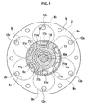
- Fig. 1 is a sectional view of the compressor of the first embodiment and Fig. 2 is a sectional view taken along the line Z-Z of Fig. 1 .
- the compressor 1 of the present embodiment is a swash plate type variable capacity compressor as shown in Fig. 1 .
- the compressor 1 has a cylinder block 2 which has substantially column-shaped cylinder bores Bj (The “j" refers to "1 to 6" in this embodiment) arranged in the circumferential direction at regular intervals (see Fig.
- a front head 4 which is attached to a front end of the cylinder block 2 and forms therein a crank chamber 5 communicating with the cylinder bores Bj, a valve plate 9 which constitutes a first partition wall and a second partition wall, and a rear head 6 which is attached to a rear end of the cylinder block 2 with the valve plate 9 therebetween so as to form therein a suction chamber 7 and a discharge chamber 8.
- the cylinder block 2, the front head 4 and the rear head 6 are attached and fastened together with through bolts 13 to constitute an overall housing of the compressor.
- a gasket 53 is provided between the valve plate 9 and the rear head 6 to seal the suction chamber 7 and the discharge chamber 8.
- a gasket 54 is provided between the valve plate 9 and the cylinder block 2 to seal the cylinder bores Bj.
- the valve plate 9 is formed in a substantially circular disk shape.
- the valve plate 9 is formed with suction holes 11j (The “j” refers to “1 to 6" in this embodiment.) corresponding to the cylinder bores Bj to communicate the cylinder bores Bj with the suction chamber 7, and discharge holes 12j (The “j” refers to "1 to 6” in this embodiment) corresponding to the cylinder bores Bj to communicate the cylinder bores Bj with the discharge chamber 8.
- a suction valve mechanism 70 is provided to open and close the suction holes 11j and a discharge valve mechanism 60 is provided to open and close the discharge hole 12j, as described below in detail.
- a drive shaft 10 is rotatably supported by radial bearings 15, 19 at center through holes 14, 18 of the front head 4 and the cylinder block 2 so that the drive shaft 10 is rotatable in the crank chamber 5.
- a thrust bearing 20 is provided between an inner surface of the front head 4 and a front end surface of the rotor 21 fixed to the drive shaft 10 in the crank chamber 5.
- a thrust bearing 16 is provided between a step portion formed on the drive shaft 10 and an adjusting screw 17 fixed to the center through hole 14 of the cylinder block 2. This structure prevents axial movements of the drive shaft 10.
- a conversion mechanism is provided to convert the rotary motion of the drive shaft 10 into reciprocation motion of the pistons Pj (The “j" refers to “1 to 6" in this embodiment).
- the conversion mechanism includes the circular disk shaped rotor 21 fixed to the drive shaft 10, a circular disk shaped swash plate 24 axially slidable on and attached at an inclination to the drive shaft 10, and a linkage mechanism 40 connecting the rotor 21 and the swash plate 24 so that the rotor 21 and the swash plate 24 rotate together with allowing an inclination angle of the swash plate 24 to change.
- the respective pistons Pj are attached to the outer peripheral part of the swash plate 24 with a pair of hemispherical-shaped piston shoes 30, 30.
- the inclination angle of the swash plate 24 is changed so as to change the piston stroke.
- the variable capacity compressor includes a pressure control mechanism.
- the pressure control mechanism includes a gas discharge passage (not shown) which communicates the crank chamber 5 with the suction chamber 7, a gas supply passage (not shown) which communicates the crank chamber 5 with the discharge chamber 8, and a control valve 33 provided in the midstream of the gas supply passage to open and close the gas supply passage.
- the gas discharge passage is kept open regardless of opening and closing the gas supply passage controlled by the control valve 33, so that the refrigerant gas in the crank chamber 5 constantly flows to the suction chamber 7 through the gas discharge passage.
- the control valve 33 opens the gas supply passage, the high-pressure refrigerant flows from the discharge chamber 8 into the crank chamber 5 through the gas supply passage. This increases the pressure in the crank chamber 5.
- the swash plate 24 decreases its inclination angle as it movies toward the cylinder block 2. As a result, the piston stroke decreases and the amount of discharge of the compressor decreases.
- valve systems 60, and 70 will be described.
- a discharge valve mechanism 60 will be explained with reference to Fig. 1 .
- the discharge valve mechanism 60 has a discharge valve plate 61.
- the discharge valve plate 61 is supported between the valve plate 9 and the rear head 6 as shown in Fig. 1 .
- the discharge valve plate 61 is configured in an elastic and flexible thin plate (such as a thin metal plate) and has reed valves 63 located to correspond to the discharge holes 12j.
- the reed valve 63 keeps the discharge hole 12j closed and, when the pressure in the cylinder bore Bj is greater then the predetermined level, the reed valve 63 is deformed to open the discharge hole 12j.
- the reed valve 63 closes the discharge hole 12j during a suction stroke and a compressing stroke but opens the discharge hole 12j during a discharging stroke after the compressing stroke. Stoppers 65 provided on the gasket 53 stop the reed valves 63 at their maximum lift positions.
- a suction valve mechanism 70 will be described in further detail with reference to Figs. 1 and 2 .
- the suction valve mechanism 70 includes a rotary valve 71, a stopper 73 and a coil spring 75 as a spring member.
- the rotary valve 71, stopper 73 and coil spring 75 are all disposed in the suction chamber 7 as shown in Fig. 1 .
- the rotary valve 71 is configured in a substantially circular disk shape with a center through hole 71b at the center of the rotary valve 71.
- An axial end 10a of the drive shaft 10 is mounted in the center through hole 71 b of the rotary valve 71 and extends through the center through hole 9c of the valve plate 9 into the suction chamber 7.
- the center through hole 71b of the rotary valve 71 and the axial end 10a of the drive shaft 10 are formed in the same noncircular shape (a hexagonal shape in this embodiment) as shown in Fig. 2 so that the rotary valve 71 is axially slidable with respect to the driving shaft 10 and rotate together with the drive shaft 10.
- Axial movements of the stopper 73 are limited by a bolt 77 which serves as a fastening means at the axial end 10a of the drive shaft 10.
- the stopper 73 has a pair of arms 73d extending toward and being connected to the rotary valve 71 so that the stopper 73 rotates together with the rotary valve 71.
- the coil spring 75 is compressed and supported between the stopper 73 and the rotary valve 71 so that the rotary valve 71 is always in close contact with the valve plate 9 as biased to the valve plate 9.
- the rotary valve 71 as shown in Fig. 2 , has a suction path 71c penetrating therethrough and formed in a circular arc hole shape.
- the suction path 71c of the rotary valve 71 sequentially overlaps with the suction holes 11j of the valve plate 9 to open the suction holes 11j in sequence (see Figs. 2 to 6 ).
- the timing of the valve open period when the suction hole 11j is opened by the suction path 71c will be explained with reference to Figs. 2 to 6 .
- the timing of the valve open period when the suction holes 11j is opened by the suction path 71c is set in synchronization with the suction stroke of the piston Pj.
- Figs. 2 to 6 show a process from when cylinder bore B 1 starts a suction stroke ( Fig. 2 ) to just before the cylinder bore B 1 starts to communicate with the suction path 71c ( Fig. 6 ), in a sequential order.
- the piston P 1 of the cylinder bore B 1 is positioned at the upper (top) dead center and the piston P 4 of the cylinder bore B 4 located 180 degree opposite to the cylinder bore B 1 is positioned at the lower (bottom) dead center.
- the piston P1 of the cylinder bore B 1 finishes its compressing and discharging stroke and is going to start its suction stroke
- the piston of the cylinder bore B 4 is going to start its compressing and discharging stroke and finish its suction stroke.
- the cylinder bores B 2 and B 3 which are located between the cylinder bore B 1 subjected to the upper dead center state and the cylinder bore B 4 subjected to the lower dead center state are subjected to compressing strokes.
- the cylinder bores B 5 and B 6 which are located between the cylinder bore B 4 subjected to the lower dead center state and the cylinder bore B 1 subjected to the upper dead center state are subjected to suction strokes.
- the suction path 71c does not communicate with the suction hole 11 1 of the cylinder bore B 1 subjected to the upper dead center state but communicates with the suction hole 11 4 of the cylinder bore B 4 subjected to the lower dead center state and communicates with the suction holes 11 5 , 11 6 of the cylinder bores B 5 , B 6 subjected to the suction strokes.
- a start timing of the valve open period in which the suction hole 11 1 (see Fig. 5 ) is opened by the suction path 71c is set later than the timing at which the piston P 1 in the cylinder bore B 1 is positioned at the upper dead center ( Fig. 2 ).
- an end timing of the valve open period in which the suction hole 11 4 is opened by the suction path 71c is set after the timing at which the piston P 4 in the cylinder bore B 4 is positioned at the lower dead center ( Fig. 2 ).
- the piston P 1 is positioned at the upper dead center in Fig. 2 , and after that, the valve open period during which the suction hole 11 1 is opened by the suction path 71 starts as shown in Fig. 4 . Further, regarding the cylinder bore B 4 , the piston P 4 is positioned at the lower dead center in Fig. 2 , and after that, the valve open period during which the suction hole 11 4 is opened by the suction path 71c ends as shown in Fig. 5 .
- the start time of the valve open period when the suction hole 11j is opened by the suction path 71c is set after the time at which the piston Pj is positioned at its upper dead center
- the end time of the valve open period when the suction hole 11j is opened by the suction path 71c is set after the time that the piston Pj is positioned at its lower dead center.
- a residual pressure release structure will be described with reference to Figs. 2 to 9 .
- the rotary valve 71 has a release path 71e.
- the release path 71e is formed as a groove which is a recess on a surface of the rotary valve 71.
- the release path 71e has an inlet 71f, two outlets 71g, 71h, and a communication part 71k which communicates the inlet 71f and the outlets 71g, 71h.
- the inlet 71f and outlets 7 1 g, 7 1 h are provided on a rotational trajectory which is to overlap with the suction holes 11j and communicate with the suction holes 11j in sequence as the rotary valve 71 rotates.
- the communication part 71k is positioned out of the rotational trajectory so as not to overlap with the suction holes 11j.
- the release path 71e is configured to release a high-pressure residual refrigerant, which was not discharged during the compressing and discharging stroke and remained in one of the cylinder bores Bj in the initial stage of the suction stroke, to other of the cylinder bores Bj having a lower pressures than the one.
- the cylinder bore B 1 is in the initial stage of the suction stroke (that is, a period after the compressing and discharging stroke ends and before the suction path 71c communicates with the cylinder bore B 1 , in this example). While the release path inlet 71f is communicating with the cylinder bore B 1 ( Figs. 3 to 5 ), the first outlet 71 g firstly communicates with the cylinder bore B 3 located just rotationally-prior to the cylinder bore B 4 which is 180 degree opposite to the cylinder bore B 1 as shown in Fig. 3 . Then, as shown in Fig. 5 , the second outlet 71h communicates with the cylinder bore B 4 which is 180 degree opposite to the cylinder bore B 1 .
- A-period refers to a period when the first outlet 71g communicates with the cylinder bore B 3 ( Fig. 3 ) and "C-period” refers to a period when the second outlet 71h communicates with the cylinder bore B 4 ( Fig. 5 ).
- a "B-period” intervenes for a moment.
- the "B-period is a period when the first outlet 71g communicates with the suction hole 11 3 of the cylinder bore B 3 and the second outlet 71h communicates with the suction hole 11 4 of the cylinder bore B 4 .
- Figs. 7 and 8 are graphs showing pressure curves of pressures in the cylinder bore B 1 , the cylinder bore B 3 , and the cylinder bore B 4 which are superimposed on one another.
- the solid line indicates the pressure curve of the cylinder bore B 1 ;
- the chain line indicates the pressure curve of the cylinder bore B 3 ; and
- the two-dot chain line indicates the pressure curve of the cylinder bore B 4 .
- ⁇ indicates a rotation angle of the rotary valve.
- Fig. 8 is an enlarged view of the initial stage ( ⁇ is from about 0° to about 30°) of the suction stroke in the cylinder bore B 1 .
- the arrows in Fig. 8 indicate flows of the high pressure residual gas from the cylinder bore B 1 to the cylinder bores B 3 and B 4 .
- the A-period, B-period and C-period in Fig. 8 correspond to the above described A-period ( Fig. 3 ), B-period ( Fig. 4 ) and C-period ( Fig. 5 ), respectively.
- This configuration uses the cylinder bore B 3 located next to the cylinder bore B 4 in the direction opposite to the rotational direction, for the cylinder bore B 1 subjected to the initial stage (A-period to C-period) of the suction stroke. Regardless of the layout of the suction path 71c, the high pressure residual refrigerant can be released right after the end of the compression and discharge stroke (that is, right after the beginning of the suction stroke). Therefore, a high suction efficiency and compression performance of the compressor can be maintained.
- the release path 71e communicates with the other cylinder bores B 2 to B 6 in sequence in the same way as the cylinder bore B 1 .
- the compressor 1 of the present embodiment includes: four or more even numbers of cylinder bores Bj spaced evenly apart from each other along the circumferential direction around the drive shaft 10; the suction chamber 7 separated from the cylinder bores Bj by the first partition wall (or the valve plate 9 in this embodiment) and communicating with the cylinder bores Bj through the suction holes 11j formed in the first partition wall; the discharge chamber 8 separated from the cylinder bores Bj by the second partition wall (or the valve plate 9 in this embodiment) and communicating with the cylinder bores Bj through discharge holes 12j formed in the second partition wall; the pistons Pj configured to reciprocate in the cylinder bores Bj; and the conversion mechanism (21, 24, 40, 30) configured to convert the rotation of the drive shaft 10 to the reciprocations of the pistons Pj.
- each cylinder bore Bj has its suction stroke and its compression and discharge stroke alternately.
- the suction stroke the refrigerant is suctioned from the suction chamber 7 into the cylinder bore Bj through the suction hole 11j.
- the compression and discharge stroke the refrigerant is compressed in the cylinder bores Bj and then the compressed refrigerant is discharged to the discharge chamber 8 through the discharge hole 12j.
- the compressor 1 further includes the rotary valve 71 disposed to be in rotational, slidable contact with the first partition wall 9 while covering the suction hole 11j and connected to the drive shaft 10 so as to rotate in synchronizing with the rotation of the drive shaft (10).
- the rotary valve (71) is formed with a suction path (71c) configured to open the suction holes 11j of the cylinder bores Bj subjected to the suction strokes so as to connect the cylinder bores Bj to the suction chamber 7.
- the rotary valve 71 is formed with the release path 71e to release a high pressure residual refrigerant which was not discharged in the compression and discharge stroke from one of the cylinder bores Bj subjected to an initial stage of the suction stroke to others of the cylinder bores Bj having a lower pressure than the one of the cylinder bores Bj.
- the release path 71e is formed with the inlet 71f, the first outlet 71g and the second outlet 71h provided on the rotational trajectory to overlap with the suction holes 11j.
- the release path 71e is formed with the communication part 71k provided outside the rotational trajectory and communicating the inlet with the outlets.
- the first outlet 71g communicates with a second one of the cylinder bores Bj next to, in a direction opposite to the rotational direction (counter-rotational direction), a third one of the cylinder bore Bj located 180 degree opposite to the first one of the cylinder bore Bj; and after that, (C) the second outlet 71h communicates with the third one of the cylinder bores Bj located at 180 degree opposite to the first one of the cylinder bores Bj.
- the first outlet 71g communicates with the cylinder bore B 3 next to, in the counter-rotational direction, the cylinder bore B 4 located 180 degree opposite to the cylinder bore B 1 (a A-period); and then, the second outlet 71h communicates with the cylinder bore B 4 located 180 degree opposite to the cylinder bore B 1 ( a C-period).
- the present embodiment uses the cylinder bore B 3 next to, in the opposite direction to the rotational direction, the cylinder bore B 4 located 180 degree opposite to the cylinder bore B 1 subjected to the initial stage of the suction stroke.
- the high pressure residual refrigerant can be released right after the end of the compression and discharge stroke (that is, right after the beginning of the suction stroke). Therefore, a high suction efficiency and compression performance of compressor can be maintained.
- the release path 71e communicates with the other cylinder bores B 2 to B6 by turns in the same way.
- the layout of the suction path 71c is designed such that the start timing of the valve open period when the suction hole 11j is opened by the suction path 71c is set later than the timing when the piston Pj in the cylinder bore Bj is positioned at its upper dead center.
- the ending time ( Fig. 4 ) of the valve open period when the suction hole 11 4 is opened by the suction path 71c is set after the timing shown in Fig. 2 in which the piston P 4 in the cylinder bore B 4 is positioned at the lower dead center.
- the suction gas is introduced into the cylinder bore Bj even after the suction stroke (the initial stage of the compression and discharge stroke, that is, a stage in which the piston Pj has started to moves from the lower dead center toward the upper dead center), by the inertia of the suction gas flow which was introduced during the suction stroke (that is, during a period when the piston Pj moves from the upper dead center to the lower dead center).
- This process increases the suction amount of gas so as to improve the suction efficiency and the compression efficiency of the compressor 1.
- This structure can not release the residual gas from one of the cylinder bores Bj having piston Pj at the upper dead center to another of the cylinder bore Bj 180 degree opposite to the one of the cylinder bores Bj.
- the residual gas can not be released from the cylinder bores B 1 ( Fig. 3 ) having piston Pj positioned right after the upper dead center to the cylinder bore B 4 located 180 degree opposite to the cylinder bore B 4 .
- the A-period and C-period are partially overlapped so that the C-period follows A-period without a break therebetween. This configuration allows release of the residual gas without a break, and thereby, the suction efficiency is further improved.
- the compressor 1 of the present embodiment includes a rotatable drive shaft 10 extending into the suction chamber 7 through the through hole 9c provided in the valve plate 9, and the plate shaped rotary valve 71 connected to the drive shaft 10 within the suction chamber 7 so as to rotate with the drive shaft 10 and configured to open and close the suction holes 11j of the valve plate 9 as rotating with the drive shaft 10; and the stopper 73, which is axially immovable, attached to the drive shaft 10, wherein the rotary valve 71 is axially slidably attached to the drive shaft 10 and biased toward the valve plate 9 by the coil spring 75 serving as a spring supported by the stopper 73.
- the rotary valve 71 rotates with the drive shaft 10 with being axially slidable with respect to the drive shaft 10 and is biased toward the valve plate 9 by the spring 75.
- the rotary valve 71 is firmly in close contact with the valve plate 9, so that the compressed high pressure medium in the cylinder bores Bj does not substantially leak from the suction holes 11j of the cylinder bores Bj through the gap between the valve plate 9 and the rotary valve 71 into the suction chamber 7.
- the compression efficiency is improved.
- the compressor 1 of the present embodiment has a safety for the excessively high pressure in the cylinder bores Bj.
- the coil spring 75 is not in contact with the rear head 6, so that vibration of the rotary valve 71 is not transmitted to the rear head 6 via the coil spring 75. Therefore, the compressor 1 of the present embodiment achieves improved suppression of vibration.
- the stopper 73 for the coil spring 75 rotates with the rotary valve 71 as one unit, unlike the conventional art (for example, Japanese Patent Application Laid-Open No. 8-144946 , Fig. 3 , 6 , 9 and 12 ), so there is no need to have a thrust bearing between the coil spring and the rotary valve or between the coil spring and the stopper. Therefore, cost is reduced since expensive thrust bearings are not required.
- Fig. 10 is a view of a rotary valve according to a first modification of the first embodiment.
- the rotary valve 71 of the first embodiment has the recessed communication part 71k of the release path 71e which is recessed from the surface of the rotary valve 71 in a groove shape (See, Fig. 9 ), the rotary valve 71 of the first modification shown in Fig. 10 has a communication part 71k which penetrates through the rotary valve 71 to form a hole therein.
- a first modification can achieve the same or similar effect as that of the first embodiment.
- Fig. 11 is a view of a rotary valve according to a second modification of the first embodiment.
- the rotary valve 71 of the first embodiment has the release path 71e in which one communication part 71k communicates one inlet 71f with two outlets 71g, 71h (See, Fig. 9 ).
- a rotary valve 71 of the second modification shown in Fig. 11 has a release path 71e with separate communication parts 71k-1, 71k-2 in which one communication part 71k-1 connects an inlet 71f to a first outlet 71g and the other communication part 71k-2 connects the inlet 71f to a second outlet 71h.
- the communication part 71k-1 and the communication part 71k-2 meet in the middle. In other words, the communication part 71k-1 and the communication part 71k-2 diverge from each other in midstream.
- Such a second modification can achieve the same or similar effect as that of the first embodiment.
- the compressor 1 of the first embodiment includes the plate-shaped rotary valve 71 configured to be in slide contact with the valve plate 9.
- the compressor 1 according to the second embodiment includes a tubular-shaped rotary valve 71A which is slidably received in a center through hole 14 of a cylinder block 2.
- Other configurations of the second embodiment are the same as that of the first embodiment.
- a tubular portion 83 projects from a rear end of the cylinder block 2 around a circumferential edge of the center through hole 1, and the tubular portion 83 of the cylinder block extends into a suction chamber 7 of a rear head 6 through a center through hole 9c of the valve plate 9.
- the valve plate 9 (or, a second partition wall) is formed with discharge holes 12 and without a suction hole.
- suction holes 11j are formed at a partition wall 85 (or, a first partition wall) by which the center through hole 14 of the cylinder block 2 and the cylinder bores Bj are separated from each other.
- the tubular rotary valve 71A is rotationally slidably provided in the center through hole 14 of the cylinder block 2 and is connected with a drive shaft 10, so that the rotary valve 71A can rotate with the drive shaft 10 as an integral unit.
- the rotary valve 71A is formed with a suction path 71c configured to communicate the suction chamber 7 to the suction holes 11j of the cylinder bores Bj subjected to a suction stroke, in turn, as the rotary valve 71A rotates.
- the rotary valve 71A is provided with a release path 71e.
- the release path 71e is formed as a recess from a surface of the rotary valve 71A, and has an inlet 71f, a first outlet 7 1 g, a second outlet 71h, and a communication part 71k connecting the inlet 71f to the outlets 71g, 71h.
- the inlet 71f and the outlets 71g, 71h are provided on a rotational trajectory which overlaps the suction holes 11j so as to connect with the suction holes 11j in sequential order as the rotary valve 71A rotates.
- the communication part 71k is outside of the rotational trajectory.
- Figs. 13 to 17 show a connection process between the release path 71e and the cylinder bores B 1 , B 4 and B 5 in a sequential order during an initial stage of a suction stroke in the cylinder bore B 1 .
- a piston P 1 of a cylinder bore B 1 is positioned at its upper dead center and a piston P 4 of a cylinder bore B 4 which is 180 degree opposite to the cylinder bore B 1 is positioned at its lower dead center.
- the first outlet 71g communicates with the cylinder bore B 3 next to, in the counter-rotational direction, the cylinder bore B 4 which is 180 degree opposite to the cylinder bore B 1 as shown in Fig. 14
- the second outlet 71h communicates with the cylinder bore B 4 which is 180 degree opposite to the cylinder bore B 1 as shown in Fig. 16 .
- A-period refers to a period when the first outlet 71g communicates with the cylinder bore B 3 ( Fig.
- C-period refers to a period when the second outlet 71h communicates with the cylinder bore B 4 ( Fig. 16 ).
- A-period Fig. 14
- C-period Fig. 16
- B-period Fig. 15
- Fig. 19 is a view of a rotary valve of a first modification of the second embodiment.
- the communication part 71k of the release path 71e is recessed from an outer circumferential surface of the rotary valve 71A and formed in a groove shape ( Figs. 13 and 18 ).
- the first modification has a communication part 71k which penetrates the rotary valve 71A to form a hole therein. Such a first modification can provide the same or similar effect as that of the second embodiment.
- Fig. 20 is a view of a rotary valve of a second modification of the second embodiment.
- the rotary valve 71A of the second embodiment is configured which a communication part 71k to connect the inlet 71f with two of the outlets 71g, 71h ( Figs. 13 , 18 ).
- the second modification has separate communication parts 71k-1, 71k-2 in which the communication part 71k-1 connects an inlet 71f of a release path 71e with a first outlet 71g and the communication part 71k-2 connects the inlet 71f with a second outlet 71h.
- the communication part 71k-1 and the communication part 71k-2 are connected to each other in midstream.
- Such a second modification can achieve the same or similar effect as that of the second embodiment.
- each of the above detailed embodiments has such a structure with six cylinder bores
- the present invention can be applied to a structure having an even number of four or more cylinder bores which is space apart from each other in a circumferential direction.
- the present invention can be implemented with various other modifications without departing from technical scope of the present invention.
Landscapes
- Engineering & Computer Science (AREA)
- Mechanical Engineering (AREA)
- General Engineering & Computer Science (AREA)
- Compressors, Vaccum Pumps And Other Relevant Systems (AREA)
- Compressor (AREA)
Abstract
Description
- The present invention relates to a compressor.
- Japanese Patent Publication No.
3079743 - The rotary valve includes a release passage. The release passage is configured to release a high pressure residual gas that remains in one of the compression chambers in which the piston therein is positioned at approximately an upper dead center thereof to other compression chambers in which the piston therein is positioned at approximately a lower dead center thereof.
- This configuration reduces the high pressure residual gas which remains in the compression chamber after the compression and discharge stroke of the associated piston. That is, the amount of the high pressure residual gas which would otherwise be re-expanded in a suction stroke is decreased. Thereby, a larger amount of the refrigerant gas can be suctioned into the compression chamber during suction strokes, so as to improve the suction efficiency and the compression efficiency of the compressor.
- In general, it is considered that a highly efficient compressor is achieved when high pressure residual gas is released from one of the cylinder bores having a piston positioned at the top dead center (a cylinder bore at an end of an compression and discharge stroke, that is, a cylinder bore at a beginning of the suction stroke) to another of the cylinder bores which is located 180-degree opposite to the one of the cylinder bores (a cylinder bore at the end of the suction stroke, that is, a cylinder bore at the beginning of the compression and discharge stroke). The highly efficient compressor is achieved because these two cylinder bores would have the largest pressure deference.
- However, depending on layouts of the suction path of the rotary valve, the residual gas may be unable to be released from one of the cylinder bores having a piston positioned around the upper dead center to another of the cylinder bores located 180-degree opposite to the one of the cylinder bores. One such example is a structure in which a termination of a connection between a cylinder bore and a suction path of a rotary valve is set after a time when a piston is positioned at a lower dead center in the cylinder bore (see Japanese Patent No.
3079741 - The present invention was developed in view of the problems described in the related art, an object of the present invention is to provide a compressor capable of releasing a residual gas right after a compression and discharge stroke, regardless of the layout of a suction path of a rotary valve
- An aspect of the present invention is a compressor (1) comprising: an even number of at least four cylinder bores (Bj) evenly spaced from each other in a circumferential direction thereof around a drive shaft (10); a suction chamber (7) separated from the cylinder bores (Bj) by a first partition wall (9, 85) and communicating with the cylinder bores (Bj) through suction holes (11j) formed in the first partition wall; a discharge chamber (8) separated from the cylinder bores (Bj) by a second partition wall (9) and communicating with the cylinder bores (Bj) through discharge holes (12j) formed in the second partition wall; a piston (Pj) reciprocatably provided in each of the cylinder bores (Bj) and configured to reciprocate in the cylinder bores (Bj) in response to rotation of the drive shaft (10) so as to perform a suction stroke and a compression and discharge stroke alternately; and a rotary valve (71) configured to be in rotary slidable contact with the first partition wall while covering the suction holes (11j) and to rotate in synchronizing with the rotation of the drive shaft (10). The rotary valve (71) is formed with: a suction path (71c) configured to open the suction holes (11j) of the cylinder bores (Bj) subjected to the suction strokes so as to connect the cylinder bores (Bj) to the suction chamber (7); and a release path (71e) configured to release a high pressure residual refrigerant which could not be discharged out in the compression and discharge stroke from one of the cylinder bores (Bj) subjected to an initial stage of the suction stroke to others of the cylinder bores (Bj) having lower pressure than the one of the cylinder bores (Bj). The release path (71e) is formed with an inlet (71f), a first outlet (71g) and a second outlet (71h) which are provided on a rotational trajectory to overlap with the suction holes (11j). The release path (71e) is formed with a communication part (71k) provided outside of the rotational trajectory and connecting the inlet and the outlets. A time period when the inlet (71f) of the release path (71e) is connected to a first one of the cylinder bores (Bj) subjected to a initial state of the suction stroke includes: an A-period when the first outlet (71g) is connected to a second one of the cylinder bores (Bj) next to, in a direction opposite to the rotational direction, a third one of the cylinder bores (Bj) which is located 180 degree opposite to the first one of the cylinder bores (Bj), and after A-period, C-period when the second outlet (71h) is connected to the third one of the cylinder bores (Bj) which is located 180 degree opposite to the first one of the cylinder bores (Bj).
- In this application, a "suction stroke" is defined as a duration when a piston moves from its upper (top) dead center to its lower (bottom) dead center, and a "compression and discharge stroke" is defined as a duration when a piston moves from its lower (bottom) dead center to its upper (top) dead center. An "end of a compression and discharge stroke" and a "beginning of a suction stroke" are defined as a time when a piston is positioned at its upper (top) dead center, an "end of a suction stroke" and a "beginning of a compression and discharge stroke" are defined as a time when a piston is positioned at its lower (bottom) dead center.
- In the suction stroke, a fluid is suctioned through the suction hole from the suction chamber into the cylinder bore. On the other hand, in the compression and discharge stroke, a fluid is compressed within the cylinder bore and the compressed fluid is discharged through the discharge hole from the cylinder bore into the discharge chamber.
-
- [
Fig. 1] Fig. 1 is a sectional view of a compressor according to a first embodiment of the present invention. - [
Fig. 2] Fig. 2 is a sectional view taken along with the line Z-Z ofFig. 1 , showing a positional relation between suction paths and a release path during a rotation of a rotary valve. - [
Fig. 3] Fig. 3 is a sectional view taken along with the line Z-Z ofFig. 1 , showing a positional relation between the suction paths and the release path during the rotation of the rotary valve. - [
Fig. 4] Fig. 4 is a sectional view taken along with the line Z-Z ofFig. 1 , showing a positional relation between the suction paths and the release path during the rotation of the rotary valve. - [
Fig. 5] Fig. 5 is a sectional view taken along with the line Z-Z ofFig. 1 , showing a positional relation between the suction paths and the release path during the rotation of the rotary valve. - [
Fig. 6] Fig. 6 is a sectional view taken along with the line Z-Z ofFig. 1 , showing a positional relation between the suction paths and the release path during the rotation of the rotary valve. - [
Fig. 7] Fig. 7 is a view of superimposed pressure curves of pressures in a cylinder bore B1, a cylinder bore B3 and a cylinder bore B4; the solid line indicates the pressure curve of the cylinder bore B1; the chain line indicates the pressure curve of the cylinder bore B3; and the two-dot chain line indicates the pressure curve of the cylinder bore B4. - [
Fig. 8] Fig. 8 is a view enlarging a term in the view ofFig. 7 , showing an initial stage of a suction stroke in the cylinder bore B1. - [
Fig. 9] Fig. 9 is a front view of the rotary valve of the compressor according to the first embodiment. - [
Fig. 10] Fig. 10 is a front view of a first modification of the rotary valve of the compressor according to the first embodiment. - [
Fig. 11] Fig. 11 is a front view of a second modification of the rotary valve of the compressor according to the first embodiment. - [
Fig. 12] Fig. 12 is a sectional view of a compressor according to the second embodiment of the present invention. - [
Fig. 13] Fig. 13 is a sectional view taken along the Z-Z ofFig. 12 , showing a positional relation between suction paths and a release path during a rotation of a rotary valve. - [
Fig. 14] Fig. 14 is a sectional view taken along the line Z-Z ofFig. 12 , showing a positional relation between the suction paths and the release path during the rotation of the rotary valve. - [
Fig. 15] Fig. 15 is a sectional view taken along the line Z-Z ofFig. 12 , showing a positional relation between the suction paths and the release path during the rotation of the rotary valve. - [
Fig. 16] Fig. 16 is a sectional view taken along the line Z-Z ofFig. 1 , showing a positional relation between the suction paths and the release path during the rotation of the rotary valve. - [
Fig. 17] Fig. 17 is a sectional view taken along the line Z-Z ofFig. 1 , showing a positional relation between the suction paths and the release path during the rotation of the rotary valve. - [
Fig. 18] Fig. 18 is an expanded view of an outer peripheral surface of the rotary valve of the compressor according to the second embodiment. - [
Fig. 19] Fig. 19 is a sectional view of a first modification of the rotary valve of the compressor according to the second embodiment. - [
Fig. 20] Fig. 20 is a sectional view of a second modification of the rotary valve of the compressor according to the second embodiment. - Embodiments of a compressor according to the present invention will be described with reference to the drawings.
- A compressor of a first embodiment will be described with reference to
Figs. 1 to 9 . -
Fig. 1 is a sectional view of the compressor of the first embodiment andFig. 2 is a sectional view taken along the line Z-Z ofFig. 1 . Thecompressor 1 of the present embodiment is a swash plate type variable capacity compressor as shown inFig. 1 . Thecompressor 1 has acylinder block 2 which has substantially column-shaped cylinder bores Bj (The "j" refers to "1 to 6" in this embodiment) arranged in the circumferential direction at regular intervals (seeFig. 2 ), afront head 4 which is attached to a front end of thecylinder block 2 and forms therein acrank chamber 5 communicating with the cylinder bores Bj, avalve plate 9 which constitutes a first partition wall and a second partition wall, and arear head 6 which is attached to a rear end of thecylinder block 2 with thevalve plate 9 therebetween so as to form therein asuction chamber 7 and adischarge chamber 8. Thecylinder block 2, thefront head 4 and therear head 6 are attached and fastened together with throughbolts 13 to constitute an overall housing of the compressor. - A
gasket 53 is provided between thevalve plate 9 and therear head 6 to seal thesuction chamber 7 and thedischarge chamber 8. Agasket 54 is provided between thevalve plate 9 and thecylinder block 2 to seal the cylinder bores Bj. - The
valve plate 9 is formed in a substantially circular disk shape. Thevalve plate 9 is formed withsuction holes 11j (The "j" refers to "1 to 6" in this embodiment.) corresponding to the cylinder bores Bj to communicate the cylinder bores Bj with thesuction chamber 7, anddischarge holes 12j (The "j" refers to "1 to 6" in this embodiment) corresponding to the cylinder bores Bj to communicate the cylinder bores Bj with thedischarge chamber 8. - On the
rear head 6 side of thevalve plate 9, asuction valve mechanism 70 is provided to open and close thesuction holes 11j and adischarge valve mechanism 60 is provided to open and close thedischarge hole 12j, as described below in detail. - A
drive shaft 10 is rotatably supported byradial bearings holes front head 4 and thecylinder block 2 so that thedrive shaft 10 is rotatable in thecrank chamber 5. - A
thrust bearing 20 is provided between an inner surface of thefront head 4 and a front end surface of therotor 21 fixed to thedrive shaft 10 in thecrank chamber 5. Athrust bearing 16 is provided between a step portion formed on thedrive shaft 10 and an adjustingscrew 17 fixed to the center throughhole 14 of thecylinder block 2. This structure prevents axial movements of thedrive shaft 10. - In the
crank chamber 5, a conversion mechanism is provided to convert the rotary motion of thedrive shaft 10 into reciprocation motion of the pistons Pj (The "j" refers to "1 to 6" in this embodiment). The conversion mechanism includes the circular disk shapedrotor 21 fixed to thedrive shaft 10, a circular disk shapedswash plate 24 axially slidable on and attached at an inclination to thedrive shaft 10, and alinkage mechanism 40 connecting therotor 21 and theswash plate 24 so that therotor 21 and theswash plate 24 rotate together with allowing an inclination angle of theswash plate 24 to change. The respective pistons Pj are attached to the outer peripheral part of theswash plate 24 with a pair of hemispherical-shaped piston shoes 30, 30. When theswash plate 24 rotates, the pistons Pj reciprocate within the cylinder bores Bj according to the inclination angle of theswash plate 24. As the pistons Pj reciprocate, a refrigerant is suctioned from thesuction chamber 7 into the cylinder bores Bj through the suction holes 11j of thevalve plate 9 and compressed in the cylinder bores Bj. The compressed refrigerant is discharged to thedischarge chamber 8 through the discharge holes 12j of thevalve plate 9. - When the
swash plate 24 moves toward thecylinder block 2 against thereturn spring 52, the inclination angle of theswash plate 24 decreases. On the other hand, the inclination angle of theswash plate 24 is increased when theswash plate 24 moves away from thecylinder block 2 against areturn spring 51. - In order to change the amount of discharged refrigerant, the inclination angle of the
swash plate 24 is changed so as to change the piston stroke. Concretely, based on a pressure difference (pressure balance) between a crank chamber pressure Pc in back of (below) the pistons Pj and a suction chamber pressure Ps in front of (above) the pistons Pj, the inclination angle of theswash plate 24 is changed so as to change the piston stroke. For this purpose, the variable capacity compressor includes a pressure control mechanism. The pressure control mechanism includes a gas discharge passage (not shown) which communicates thecrank chamber 5 with thesuction chamber 7, a gas supply passage (not shown) which communicates thecrank chamber 5 with thedischarge chamber 8, and acontrol valve 33 provided in the midstream of the gas supply passage to open and close the gas supply passage. - The gas discharge passage is kept open regardless of opening and closing the gas supply passage controlled by the
control valve 33, so that the refrigerant gas in thecrank chamber 5 constantly flows to thesuction chamber 7 through the gas discharge passage. - When the
control valve 33 opens the gas supply passage, the high-pressure refrigerant flows from thedischarge chamber 8 into thecrank chamber 5 through the gas supply passage. This increases the pressure in thecrank chamber 5. When the pressure in thecrank chamber 5 increases, theswash plate 24 decreases its inclination angle as it movies toward thecylinder block 2. As a result, the piston stroke decreases and the amount of discharge of the compressor decreases. - On the other hand, when the
control valve 33 closes the gas supply passage, the pressure difference between the pressure in thesuction chamber 7 and the pressure in thecrank chamber 5 is equalized. As a result, the inclination angle of theswash plate 24 increases as theswash plate 24 moves away from thecylinder block 2, so that the piston stroke increases and the amount of discharge of the compressor increases. - Next,
valve systems - A
discharge valve mechanism 60 will be explained with reference toFig. 1 . Thedischarge valve mechanism 60 has adischarge valve plate 61. Thedischarge valve plate 61 is supported between thevalve plate 9 and therear head 6 as shown inFig. 1 . Thedischarge valve plate 61 is configured in an elastic and flexible thin plate (such as a thin metal plate) and hasreed valves 63 located to correspond to thedischarge holes 12j. When a pressure in the cylinder bore Bj is equal to or less than a predetermined level, thereed valve 63 keeps thedischarge hole 12j closed and, when the pressure in the cylinder bore Bj is greater then the predetermined level, thereed valve 63 is deformed to open thedischarge hole 12j. In other words, thereed valve 63 closes thedischarge hole 12j during a suction stroke and a compressing stroke but opens thedischarge hole 12j during a discharging stroke after the compressing stroke.Stoppers 65 provided on thegasket 53 stop thereed valves 63 at their maximum lift positions.
Next, asuction valve mechanism 70 will be described in further detail with reference toFigs. 1 and2 . - The
suction valve mechanism 70 includes arotary valve 71, astopper 73 and acoil spring 75 as a spring member. Therotary valve 71,stopper 73 andcoil spring 75 are all disposed in thesuction chamber 7 as shown inFig. 1 . - The
rotary valve 71 is configured in a substantially circular disk shape with a center throughhole 71b at the center of therotary valve 71. Anaxial end 10a of thedrive shaft 10 is mounted in the center throughhole 71 b of therotary valve 71 and extends through the center throughhole 9c of thevalve plate 9 into thesuction chamber 7. The center throughhole 71b of therotary valve 71 and theaxial end 10a of thedrive shaft 10 are formed in the same noncircular shape (a hexagonal shape in this embodiment) as shown inFig. 2 so that therotary valve 71 is axially slidable with respect to the drivingshaft 10 and rotate together with thedrive shaft 10. - Axial movements of the
stopper 73 are limited by abolt 77 which serves as a fastening means at theaxial end 10a of thedrive shaft 10. Thestopper 73 has a pair ofarms 73d extending toward and being connected to therotary valve 71 so that thestopper 73 rotates together with therotary valve 71. Thecoil spring 75 is compressed and supported between thestopper 73 and therotary valve 71 so that therotary valve 71 is always in close contact with thevalve plate 9 as biased to thevalve plate 9. - The
rotary valve 71, as shown inFig. 2 , has asuction path 71c penetrating therethrough and formed in a circular arc hole shape. When therotary valve 71 rotates, thesuction path 71c of therotary valve 71 sequentially overlaps with the suction holes 11j of thevalve plate 9 to open thesuction holes 11j in sequence (seeFigs. 2 to 6 ). - Next, the timing of the valve open period when the
suction hole 11j is opened by thesuction path 71c will be explained with reference toFigs. 2 to 6 . Here, the timing of the valve open period when thesuction holes 11j is opened by thesuction path 71c is set in synchronization with the suction stroke of the piston Pj. -
Figs. 2 to 6 show a process from when cylinder bore B1 starts a suction stroke (Fig. 2 ) to just before the cylinder bore B1 starts to communicate with thesuction path 71c (Fig. 6 ), in a sequential order. - In a position shown in
Fig. 2 , the piston P1 of the cylinder bore B1 is positioned at the upper (top) dead center and the piston P4 of the cylinder bore B4 located 180 degree opposite to the cylinder bore B1 is positioned at the lower (bottom) dead center. Thus, in the position shown inFig. 2 , the piston P1 of the cylinder bore B1 finishes its compressing and discharging stroke and is going to start its suction stroke, and the piston of the cylinder bore B4 is going to start its compressing and discharging stroke and finish its suction stroke. Further, the cylinder bores B2 and B3 which are located between the cylinder bore B1 subjected to the upper dead center state and the cylinder bore B4 subjected to the lower dead center state are subjected to compressing strokes. The cylinder bores B5 and B6 which are located between the cylinder bore B4 subjected to the lower dead center state and the cylinder bore B1 subjected to the upper dead center state are subjected to suction strokes. - In such a position shown in
Fig. 2 , thesuction path 71c does not communicate with thesuction hole 111 of the cylinder bore B1 subjected to the upper dead center state but communicates with thesuction hole 114 of the cylinder bore B4 subjected to the lower dead center state and communicates with the suction holes 115, 116 of the cylinder bores B5, B6 subjected to the suction strokes. - Thus, regarding the cylinder bore B1 in
Figs. 2 to 6 , a start timing of the valve open period in which the suction hole 111 (seeFig. 5 ) is opened by thesuction path 71c is set later than the timing at which the piston P1 in the cylinder bore B1 is positioned at the upper dead center (Fig. 2 ). Further, regarding the cylinder bore B4 inFigs. 2 to 6 , an end timing of the valve open period in which thesuction hole 114 is opened by thesuction path 71c (Fig. 4 ) is set after the timing at which the piston P4 in the cylinder bore B4 is positioned at the lower dead center (Fig. 2 ). - In other words, regarding the cylinder bore B1, the piston P1 is positioned at the upper dead center in
Fig. 2 , and after that, the valve open period during which thesuction hole 111 is opened by thesuction path 71 starts as shown inFig. 4 . Further, regarding the cylinder bore B4, the piston P4 is positioned at the lower dead center inFig. 2 , and after that, the valve open period during which thesuction hole 114 is opened by thesuction path 71c ends as shown inFig. 5 . - That is, in each cylinder bore Bj, the start time of the valve open period when the
suction hole 11j is opened by thesuction path 71c is set after the time at which the piston Pj is positioned at its upper dead center, and the end time of the valve open period when thesuction hole 11j is opened by thesuction path 71c is set after the time that the piston Pj is positioned at its lower dead center. - As described above, in each cylinder bores Bj, the end timing of the valve open period when the
suction hole 11j is opened by thesuction path 71c is set after the time the piston Pj is positioned at the lower dead center. With this structure, suction gas is introduced into the cylinder bore Bj even in an initial stage of the compression and discharge stroke after the suction stroke (when the piston Pj has started to move from the lower dead center toward the upper dead center) because of an inertia of a suction gas flow which was introduced during the suction stroke (while the piston Pj moves from the upper dead center to the lower dead center). This increases the suctioned amount so as to improve the suction efficiency and the compression efficiency of thecompressor 1. - A residual pressure release structure will be described with reference to
Figs. 2 to 9 . - As shown in
Figs. 1 to 6 and9 , therotary valve 71 has arelease path 71e. - The
release path 71e is formed as a groove which is a recess on a surface of therotary valve 71. Therelease path 71e has aninlet 71f, twooutlets communication part 71k which communicates theinlet 71f and theoutlets inlet 71f andoutlets 7 1 g, 7 1 h are provided on a rotational trajectory which is to overlap with thesuction holes 11j and communicate with thesuction holes 11j in sequence as therotary valve 71 rotates. Thecommunication part 71k is positioned out of the rotational trajectory so as not to overlap with thesuction holes 11j. - The
release path 71e is configured to release a high-pressure residual refrigerant, which was not discharged during the compressing and discharging stroke and remained in one of the cylinder bores Bj in the initial stage of the suction stroke, to other of the cylinder bores Bj having a lower pressures than the one. - The following description will describe how the
release path 71e of therotary valve 71 and the cylinder bores Bj communicate with each other during a period from the time of a beginning of the suction stroke in the cylinder bore B1 (Fig. 2 ) to the time just before the cylinder bore B1 starts to communicate with thesuction path 71c (Fig. 6 ), with reference toFigs. 2 to 6 . - Through
Figs. 2 to 6 , the cylinder bore B1 is in the initial stage of the suction stroke (that is, a period after the compressing and discharging stroke ends and before thesuction path 71c communicates with the cylinder bore B1, in this example). While therelease path inlet 71f is communicating with the cylinder bore B1 (Figs. 3 to 5 ), thefirst outlet 71 g firstly communicates with the cylinder bore B3 located just rotationally-prior to the cylinder bore B4 which is 180 degree opposite to the cylinder bore B1 as shown inFig. 3 . Then, as shown inFig. 5 , thesecond outlet 71h communicates with the cylinder bore B4 which is 180 degree opposite to the cylinder bore B1. - Hereinafter, "A-period" refers to a period when the
first outlet 71g communicates with the cylinder bore B3 (Fig. 3 ) and "C-period" refers to a period when thesecond outlet 71h communicates with the cylinder bore B4 (Fig. 5 ). Between the A-period (Fig. 3 ) and C-period (Fig. 5 ), a "B-period" (Fig. 4 ) intervenes for a moment. The "B-period is a period when thefirst outlet 71g communicates with thesuction hole 113 of the cylinder bore B3 and thesecond outlet 71h communicates with thesuction hole 114 of the cylinder bore B4. -
Figs. 7 and8 are graphs showing pressure curves of pressures in the cylinder bore B1, the cylinder bore B3, and the cylinder bore B4 which are superimposed on one another. InFigs. 7 and8 , the solid line indicates the pressure curve of the cylinder bore B1; the chain line indicates the pressure curve of the cylinder bore B3; and the two-dot chain line indicates the pressure curve of the cylinder bore B4. - In
Figs. 7 and8 , "θ" indicates a rotation angle of the rotary valve. InFigs. 7 and8 , when the cylinder bore B1 is subjected to the upper dead center state (when the piston P1 of the cylinder bore B1 is positioned at its upper dead center), that is, when the cylinder bore B4 is subjected to the lower dead center state (when the piston P4 of the cylinder bore B4 is positioned at its lower dead center), the rotation angle θ is indicated by 0° (= 360°). -
Fig. 8 is an enlarged view of the initial stage (θ is from about 0° to about 30°) of the suction stroke in the cylinder bore B1. The arrows inFig. 8 indicate flows of the high pressure residual gas from the cylinder bore B1 to the cylinder bores B3 and B4. The A-period, B-period and C-period inFig. 8 correspond to the above described A-period (Fig. 3 ), B-period (Fig. 4 ) and C-period (Fig. 5 ), respectively. - According to the present embodiment as shown in
Fig. 8 , regarding the cylinder bore B1 subjected to the initial stage of the suction stroke, before the C-period (Fig. 5 ) when thesecond outlet 71h communicates with the cylinder bore B4 which is 180 degree opposite to the cylinder bore B1, there is an A-period (Fig. 3 ) when thefirst outlet 71g communicates with the cylinder bore B3 next to, in an opposite direction to the rotational direction, the cylinder bore B4 which is 180 degree opposite to the cylinder bore B1. This configuration uses the cylinder bore B3 located next to the cylinder bore B4 in the direction opposite to the rotational direction, for the cylinder bore B1 subjected to the initial stage (A-period to C-period) of the suction stroke. Regardless of the layout of thesuction path 71c, the high pressure residual refrigerant can be released right after the end of the compression and discharge stroke (that is, right after the beginning of the suction stroke). Therefore, a high suction efficiency and compression performance of the compressor can be maintained. - Although the cylinder bore B1 has been used as one example in the above explanation in
Figs. 2 to 6 , therelease path 71e communicates with the other cylinder bores B2 to B6 in sequence in the same way as the cylinder bore B1. - Next, effects of the present embodiment will be described.
- (1) The
compressor 1 of the present embodiment includes: four or more even numbers of cylinder bores Bj spaced evenly apart from each other along the circumferential direction around thedrive shaft 10; thesuction chamber 7 separated from the cylinder bores Bj by the first partition wall (or thevalve plate 9 in this embodiment) and communicating with the cylinder bores Bj through thesuction holes 11j formed in the first partition wall; thedischarge chamber 8 separated from the cylinder bores Bj by the second partition wall (or thevalve plate 9 in this embodiment) and communicating with the cylinder bores Bj throughdischarge holes 12j formed in the second partition wall; the pistons Pj configured to reciprocate in the cylinder bores Bj; and the conversion mechanism (21, 24, 40, 30) configured to convert the rotation of thedrive shaft 10 to the reciprocations of the pistons Pj. The pistons Pj reciprocate in the respective cylinder bores Bj, in order, in conjunction with the rotation of thedrive shaft 10 so that each cylinder bore Bj has its suction stroke and its compression and discharge stroke alternately. In the suction stroke, the refrigerant is suctioned from thesuction chamber 7 into the cylinder bore Bj through thesuction hole 11j. In the compression and discharge stroke, the refrigerant is compressed in the cylinder bores Bj and then the compressed refrigerant is discharged to thedischarge chamber 8 through thedischarge hole 12j. Thecompressor 1 further includes therotary valve 71 disposed to be in rotational, slidable contact with thefirst partition wall 9 while covering thesuction hole 11j and connected to thedrive shaft 10 so as to rotate in synchronizing with the rotation of the drive shaft (10). The rotary valve (71) is formed with a suction path (71c) configured to open the suction holes 11j of the cylinder bores Bj subjected to the suction strokes so as to connect the cylinder bores Bj to thesuction chamber 7. Therotary valve 71 is formed with therelease path 71e to release a high pressure residual refrigerant which was not discharged in the compression and discharge stroke from one of the cylinder bores Bj subjected to an initial stage of the suction stroke to others of the cylinder bores Bj having a lower pressure than the one of the cylinder bores Bj. Therelease path 71e is formed with theinlet 71f, thefirst outlet 71g and thesecond outlet 71h provided on the rotational trajectory to overlap with thesuction holes 11j. Therelease path 71e is formed with thecommunication part 71k provided outside the rotational trajectory and communicating the inlet with the outlets. - During the time period when the
inlet 71f of therelease path 71e communicates with first one of the cylinder bore Bj which is in the initial state of the suction stroke, (A) thefirst outlet 71g communicates with a second one of the cylinder bores Bj next to, in a direction opposite to the rotational direction (counter-rotational direction), a third one of the cylinder bore Bj located 180 degree opposite to the first one of the cylinder bore Bj; and after that, (C) thesecond outlet 71h communicates with the third one of the cylinder bores Bj located at 180 degree opposite to the first one of the cylinder bores Bj. - Regarding the cylinder bore B1 as one example, in a time period (
Figs. 3 to 5 ) during which theinlet 71f of therelease path 71e communicates with the cylinder bore B1 subjected to an initial state of its suction stroke (that is, a period after a compression and discharge stroke of the cylinder bore B1 and before thesuction path 71c communicates with the cylinder bore B1), thefirst outlet 71g communicates with the cylinder bore B3 next to, in the counter-rotational direction, the cylinder bore B4 located 180 degree opposite to the cylinder bore B1 (a A-period); and then, thesecond outlet 71h communicates with the cylinder bore B4 located 180 degree opposite to the cylinder bore B1( a C-period). - As described above, the present embodiment uses the cylinder bore B3 next to, in the opposite direction to the rotational direction, the cylinder bore B4 located 180 degree opposite to the cylinder bore B1 subjected to the initial stage of the suction stroke. Thus, regardless of the layout of the
suction path 71c, the high pressure residual refrigerant can be released right after the end of the compression and discharge stroke (that is, right after the beginning of the suction stroke). Therefore, a high suction efficiency and compression performance of compressor can be maintained. - Although the cylinder bore B1 has been used as one example in the explanation through
Fig. 2 to 6 , therelease path 71e communicates with the other cylinder bores B2 to B6 by turns in the same way. - (2) According to the present embodiment, the layout of the
suction path 71c is designed such that the start timing of the valve open period when thesuction hole 11j is opened by thesuction path 71c is set later than the timing when the piston Pj in the cylinder bore Bj is positioned at its upper dead center. - In other words, regarding the cylinder bores B1, B4 which are 180 degree opposite to each other, the ending time (
Fig. 4 ) of the valve open period when thesuction hole 114 is opened by thesuction path 71c is set after the timing shown inFig. 2 in which the piston P4 in the cylinder bore B4 is positioned at the lower dead center. - Therefore, the suction gas is introduced into the cylinder bore Bj even after the suction stroke (the initial stage of the compression and discharge stroke, that is, a stage in which the piston Pj has started to moves from the lower dead center toward the upper dead center), by the inertia of the suction gas flow which was introduced during the suction stroke (that is, during a period when the piston Pj moves from the upper dead center to the lower dead center). This process increases the suction amount of gas so as to improve the suction efficiency and the compression efficiency of the
compressor 1. - This structure, however, can not release the residual gas from one of the cylinder bores Bj having piston Pj at the upper dead center to another of the
cylinder bore Bj 180 degree opposite to the one of the cylinder bores Bj. In other words, as for the cylinder bores B1 and B4 that are 180 degree opposite to each other, the residual gas can not be released from the cylinder bores B1 (Fig. 3 ) having piston Pj positioned right after the upper dead center to the cylinder bore B4 located 180 degree opposite to the cylinder bore B4. In the same way, although explanations by drawings are omitted here, in the case of the cylinder bores B2 and B5 that are 180 degree opposite to each other and the case of the cylinder bores B1 and B4 that are 180 degree opposite to each other, when their pistons are positioned right after the upper dead center, a residual gas can not be released. Therefore, the effect (1) will be more effective. - (3) According to the present embodiment, the A-period and C-period are partially overlapped so that the C-period follows A-period without a break therebetween. This configuration allows release of the residual gas without a break, and thereby, the suction efficiency is further improved.
- (4) The
compressor 1 of the present embodiment includes arotatable drive shaft 10 extending into thesuction chamber 7 through the throughhole 9c provided in thevalve plate 9, and the plate shapedrotary valve 71 connected to thedrive shaft 10 within thesuction chamber 7 so as to rotate with thedrive shaft 10 and configured to open and close the suction holes 11j of thevalve plate 9 as rotating with thedrive shaft 10; and thestopper 73, which is axially immovable, attached to thedrive shaft 10, wherein therotary valve 71 is axially slidably attached to thedrive shaft 10 and biased toward thevalve plate 9 by thecoil spring 75 serving as a spring supported by thestopper 73. - In other words, the
rotary valve 71 rotates with thedrive shaft 10 with being axially slidable with respect to thedrive shaft 10 and is biased toward thevalve plate 9 by thespring 75. With this structure, therotary valve 71 is firmly in close contact with thevalve plate 9, so that the compressed high pressure medium in the cylinder bores Bj does not substantially leak from the suction holes 11j of the cylinder bores Bj through the gap between thevalve plate 9 and therotary valve 71 into thesuction chamber 7. Thereby, the compression efficiency is improved. Moreover, if the pressure within the cylinder bores Bj was to increase excessively, therotary valve 71 would move away from thevalve plate 9 to release the excessively high pressure medium from the cylinder bores Bj to thesuction chamber 7. Therefore, thecompressor 1 of the present embodiment has a safety for the excessively high pressure in the cylinder bores Bj. - Unlike the conventional art (for example, Japanese Patent Application Laid-Open No.
8-144946 Figs. 3 ,6 ,9 and12 ), thecoil spring 75 is not in contact with therear head 6, so that vibration of therotary valve 71 is not transmitted to therear head 6 via thecoil spring 75. Therefore, thecompressor 1 of the present embodiment achieves improved suppression of vibration. - Moreover, the
stopper 73 for thecoil spring 75 rotates with therotary valve 71 as one unit, unlike the conventional art (for example, Japanese Patent Application Laid-Open No.8-144946 Fig. 3 ,6 ,9 and12 ), so there is no need to have a thrust bearing between the coil spring and the rotary valve or between the coil spring and the stopper. Therefore, cost is reduced since expensive thrust bearings are not required. - Next, modifications of the first embodiment will be explained. In modifications or embodiments described below, the same reference numerals and symbols will be used to designate the same elements as the elements described in the first embodiment, and redundant description for the elements and its effects will be omitted.
-
Fig. 10 is a view of a rotary valve according to a first modification of the first embodiment. - Although the
rotary valve 71 of the first embodiment has the recessedcommunication part 71k of therelease path 71e which is recessed from the surface of therotary valve 71 in a groove shape (See,Fig. 9 ), therotary valve 71 of the first modification shown inFig. 10 has acommunication part 71k which penetrates through therotary valve 71 to form a hole therein. Such a first modification can achieve the same or similar effect as that of the first embodiment. -
Fig. 11 is a view of a rotary valve according to a second modification of the first embodiment. - The
rotary valve 71 of the first embodiment has therelease path 71e in which onecommunication part 71k communicates oneinlet 71f with twooutlets Fig. 9 ). However, arotary valve 71 of the second modification shown inFig. 11 has arelease path 71e withseparate communication parts 71k-1, 71k-2 in which onecommunication part 71k-1 connects aninlet 71f to afirst outlet 71g and theother communication part 71k-2 connects theinlet 71f to asecond outlet 71h. Thecommunication part 71k-1 and thecommunication part 71k-2 meet in the middle. In other words, thecommunication part 71k-1 and thecommunication part 71k-2 diverge from each other in midstream. Such a second modification can achieve the same or similar effect as that of the first embodiment. - Next, a second embodiment according to the present invention will be explained with reference to
Figs. 12 to 18 . - The
compressor 1 of the first embodiment includes the plate-shapedrotary valve 71 configured to be in slide contact with thevalve plate 9. Thecompressor 1 according to the second embodiment includes a tubular-shapedrotary valve 71A which is slidably received in a center throughhole 14 of acylinder block 2. Other configurations of the second embodiment are the same as that of the first embodiment. - In particular, as shown in
Figs. 12 and13 , atubular portion 83 projects from a rear end of thecylinder block 2 around a circumferential edge of the center throughhole 1, and thetubular portion 83 of the cylinder block extends into asuction chamber 7 of arear head 6 through a center throughhole 9c of thevalve plate 9. With this configuration, the center throughhole 14 of thecylinder block 2 communicates with thesuction chamber 7. The valve plate 9 (or, a second partition wall) is formed with discharge holes 12 and without a suction hole. However,suction holes 11j are formed at a partition wall 85 (or, a first partition wall) by which the center throughhole 14 of thecylinder block 2 and the cylinder bores Bj are separated from each other. The tubularrotary valve 71A is rotationally slidably provided in the center throughhole 14 of thecylinder block 2 and is connected with adrive shaft 10, so that therotary valve 71A can rotate with thedrive shaft 10 as an integral unit. - Similar to the first embodiment, the
rotary valve 71A is formed with asuction path 71c configured to communicate thesuction chamber 7 to the suction holes 11j of the cylinder bores Bj subjected to a suction stroke, in turn, as therotary valve 71A rotates. Like the first embodiment, therotary valve 71A is provided with arelease path 71e. Therelease path 71e is formed as a recess from a surface of therotary valve 71A, and has aninlet 71f, afirst outlet 7 1 g, asecond outlet 71h, and acommunication part 71k connecting theinlet 71f to theoutlets inlet 71f and theoutlets suction holes 11j so as to connect with thesuction holes 11j in sequential order as therotary valve 71A rotates. Thecommunication part 71k is outside of the rotational trajectory. -
Figs. 13 to 17 show a connection process between therelease path 71e and the cylinder bores B1, B4 and B5 in a sequential order during an initial stage of a suction stroke in the cylinder bore B1. In a position shown inFig. 13 , a piston P1 of a cylinder bore B1 is positioned at its upper dead center and a piston P4 of a cylinder bore B4 which is 180 degree opposite to the cylinder bore B1 is positioned at its lower dead center. Thus, in the position shown inFig. 13 , in cylinder bores B2 and B3 which are located between the cylinder bore B1 subjected to the upper dead center state and the cylinder bore B4 subjected to the lower dead center state, compressing strokes are performed, and in cylinder bores B5 and B6 which are located between the cylinder bore B4 subjected to the lower dead center state and the cylinder bore B1 subjected to the upper dead center state, suction strokes are performed. - In a period (
Figs. 14 to 16 ) during which therelease path inlet 71f is connected to the cylinder bore B1 subjected to the initial stage of the suction stroke, thefirst outlet 71g communicates with the cylinder bore B3 next to, in the counter-rotational direction, the cylinder bore B4 which is 180 degree opposite to the cylinder bore B1 as shown inFig. 14 , and after that, thesecond outlet 71h communicates with the cylinder bore B4 which is 180 degree opposite to the cylinder bore B1 as shown inFig. 16 . Hereinafter, "A-period" refers to a period when thefirst outlet 71g communicates with the cylinder bore B3 (Fig. 14 ) and "C-period" refers to a period when thesecond outlet 71h communicates with the cylinder bore B4 (Fig. 16 ). Between the A-period (Fig. 14 ) and the C-period (Fig. 16 ), there is a momentary B-period (Fig. 15 ) when thefirst outlet 71g communicates with thesuction hole 113 of the cylinder bore B3 and thesecond outlet 71h communicates with thesuction hole 114 of the cylinder bore B4. - With this configuration, the same or similar effect as to the first embodiment can be achieved.
-
Fig. 19 is a view of a rotary valve of a first modification of the second embodiment. - In the
rotary valve 71A of the second embodiment, thecommunication part 71k of therelease path 71e is recessed from an outer circumferential surface of therotary valve 71A and formed in a groove shape (Figs. 13 and18 ). The first modification has acommunication part 71k which penetrates therotary valve 71A to form a hole therein. Such a first modification can provide the same or similar effect as that of the second embodiment. -
Fig. 20 is a view of a rotary valve of a second modification of the second embodiment. - The
rotary valve 71A of the second embodiment is configured which acommunication part 71k to connect theinlet 71f with two of theoutlets Figs. 13 ,18 ). The second modification hasseparate communication parts 71k-1, 71k-2 in which thecommunication part 71k-1 connects aninlet 71f of arelease path 71e with afirst outlet 71g and thecommunication part 71k-2 connects theinlet 71f with asecond outlet 71h. Thecommunication part 71k-1 and thecommunication part 71k-2 are connected to each other in midstream. Such a second modification can achieve the same or similar effect as that of the second embodiment. - It should be appreciated that the present invention is not limited to the above detailed embodiments and modifications.
- For example, although each of the above detailed embodiments has such a structure with six cylinder bores, the present invention can be applied to a structure having an even number of four or more cylinder bores which is space apart from each other in a circumferential direction. In addition, the present invention can be implemented with various other modifications without departing from technical scope of the present invention.
Claims (2)
- A compressor (1) comprising:an even number of at least four of cylinder bores (Bj) evenly spaced from each other in a circumferential direction thereof around a drive shaft (10);a suction chamber (7) separated from the cylinder bores (Bj) by a first partition wall (9, 85) provided with suction holes (11j) and configured to communicate with the cylinder bores (Bj) through the suction holes;a discharge chamber(8) separated from the cylinder bores (Bj) by a second partition wall (9) provided with discharge holes (12j) and configured to communicate with the cylinder bores (Bj) through the discharge holes;a piston (Pj) provided in each of the cylinder bores (Bj) and configured to reciprocate in the cylinder bores (Bj) in response to rotation of the drive shaft (10) so as to perform a suction stroke and a compression and discharge stroke alternately; anda rotary valve (71) configured to be in rotary slidable contact with the first partition wall while covering the suction holes (11j) and to rotate in synchronizing with the rotation of the drive shaft (10),the rotary valve (71)includes:a suction path (71c) configured to open the suction holes (11j) of the cylinder bores (Bj) subjected to the suction strokes so as to connect the cylinder bores (Bj) to the suction chamber (7); anda release path (71e) configured to release a high pressure residual refrigerant which could not be discharged in the compression and discharge stroke from one of the cylinder bores (Bj) subjected to an initial stage of the suction stroke to others of the cylinder bores (Bj) having a lower pressure than the one of the cylinder bores (Bj), the release path (71e) including: an inlet (71f), a first outlet (71g) and a second outlet (71h) which are provided on a rotational trajectory to overlap with the suction holes (11j); and a communication part (71k) provided outside of the rotational trajectory and connecting the inlet and the outlets;wherein, a time period when the inlet (71f) of the release path (71e) is connected to a first one of the cylinder bores (Bj) subjected to an initial state of the suction stroke include: an A-period when the first outlet (71g) is connected to a second one of the cylinder bores (Bj) next to, in a counter-rotational direction, a third one of the cylinder bores (Bj) which is located 180 degree opposite to the first one of the cylinder bores (Bj), and after the A-period, a C-period when the second outlet (71h) is connected to the third one of the cylinder bores (Bj) which is 180 degree opposite to the first one of the cylinder bores (Bj).
- The compressor according to Claim 1, wherein
the A-period and the C-period are partially overlapped so that the C-period follows the A-period without a break therebetween.
Applications Claiming Priority (2)
| Application Number | Priority Date | Filing Date | Title |
|---|---|---|---|
| JP2006203653A JP5033372B2 (en) | 2006-07-26 | 2006-07-26 | Compressor |
| PCT/JP2007/064555 WO2008013190A1 (en) | 2006-07-26 | 2007-07-25 | Compressor |
Publications (2)
| Publication Number | Publication Date |
|---|---|
| EP2045466A1 true EP2045466A1 (en) | 2009-04-08 |
| EP2045466A4 EP2045466A4 (en) | 2016-12-14 |
Family
ID=38981501
Family Applications (1)
| Application Number | Title | Priority Date | Filing Date |
|---|---|---|---|
| EP07791271.5A Withdrawn EP2045466A4 (en) | 2006-07-26 | 2007-07-25 | Compressor |
Country Status (6)
| Country | Link |
|---|---|
| US (1) | US20100021318A1 (en) |
| EP (1) | EP2045466A4 (en) |
| JP (1) | JP5033372B2 (en) |
| KR (1) | KR20090031948A (en) |
| CN (1) | CN101495752B (en) |
| WO (1) | WO2008013190A1 (en) |
Families Citing this family (8)
| Publication number | Priority date | Publication date | Assignee | Title |
|---|---|---|---|---|
| US8485794B2 (en) * | 2008-06-13 | 2013-07-16 | Doowon Technical College | Reciprocating compressor with rotary valve |
| KR100943703B1 (en) | 2008-06-13 | 2010-02-23 | 학교법인 두원학원 | Reciprocal compressor having rotary valve |
| JP5324893B2 (en) * | 2008-11-18 | 2013-10-23 | サンデン株式会社 | Compressor valve plate device |
| BR112014013732A8 (en) * | 2011-12-07 | 2017-06-13 | Ecothermics Corp | axial piston high pressure compressor / pump |
| US9399988B2 (en) * | 2012-02-02 | 2016-07-26 | General Electric Company | Variable capacity compressor and refrigerator |
| JP6201575B2 (en) | 2013-09-27 | 2017-09-27 | 株式会社豊田自動織機 | Variable capacity swash plate compressor |
| PT3469671T (en) | 2016-06-09 | 2020-10-09 | Balmoral Comtec Ltd | Weak link latch |
| KR20200004075A (en) | 2018-07-03 | 2020-01-13 | 현대자동차주식회사 | Rotated valve plate compressor |
Family Cites Families (12)
| Publication number | Priority date | Publication date | Assignee | Title |
|---|---|---|---|---|
| JPS58209141A (en) | 1982-05-31 | 1983-12-06 | Hitachi Ltd | Inspection system of rule on design for layout |
| US4712982A (en) * | 1985-03-25 | 1987-12-15 | Kabushiki Kaisha Toyoda Jidoshokki Seisakusho | Variable displacement wobble plate type compressor with guide means for wobble plate |
| JPS62204374A (en) | 1986-03-04 | 1987-09-09 | Fujitsu Ltd | Processing system for double arithmetic optimization |
| JPH06117367A (en) * | 1992-10-02 | 1994-04-26 | Toyota Autom Loom Works Ltd | Reciprocating compressor |
| JP3080279B2 (en) * | 1992-10-05 | 2000-08-21 | 株式会社豊田自動織機製作所 | Reciprocating compressor |
| JP3111693B2 (en) * | 1992-10-14 | 2000-11-27 | 株式会社豊田自動織機製作所 | Reciprocating compressor |
| JPH06221264A (en) * | 1993-01-25 | 1994-08-09 | Toyota Autom Loom Works Ltd | Reciprocation type compressor |
| JPH06288349A (en) * | 1993-04-06 | 1994-10-11 | Toyota Autom Loom Works Ltd | Reciprocating type compressor |
| JPH08144946A (en) | 1994-11-24 | 1996-06-04 | Sanden Corp | Intake and delivery mechanism for compressor |
| WO2002061279A1 (en) * | 2001-02-02 | 2002-08-08 | Luk Fahrzeug-Hydraulik Gmbh & Co. Kg | Reciprocating piston machine |
| CN1455085A (en) * | 2002-04-29 | 2003-11-12 | 乐金电子(天津)电器有限公司 | Compression section of sealed compressor |
| JP2004293543A (en) * | 2003-03-13 | 2004-10-21 | Sanden Corp | Compressor |
-
2006
- 2006-07-26 JP JP2006203653A patent/JP5033372B2/en not_active Expired - Fee Related
-
2007
- 2007-07-25 KR KR1020097003466A patent/KR20090031948A/en not_active Application Discontinuation
- 2007-07-25 CN CN200780028242XA patent/CN101495752B/en not_active Expired - Fee Related
- 2007-07-25 EP EP07791271.5A patent/EP2045466A4/en not_active Withdrawn
- 2007-07-25 US US12/374,868 patent/US20100021318A1/en not_active Abandoned
- 2007-07-25 WO PCT/JP2007/064555 patent/WO2008013190A1/en active Application Filing
Non-Patent Citations (1)
| Title |
|---|
| See references of WO2008013190A1 * |
Also Published As
| Publication number | Publication date |
|---|---|
| US20100021318A1 (en) | 2010-01-28 |
| CN101495752A (en) | 2009-07-29 |
| EP2045466A4 (en) | 2016-12-14 |
| WO2008013190A1 (en) | 2008-01-31 |
| JP2008031866A (en) | 2008-02-14 |
| CN101495752B (en) | 2012-07-04 |
| JP5033372B2 (en) | 2012-09-26 |
| KR20090031948A (en) | 2009-03-30 |
Similar Documents
| Publication | Publication Date | Title |
|---|---|---|
| EP2045466A1 (en) | Compressor | |
| EP2045465A1 (en) | Compressor | |
| JP2001153043A (en) | Variable displacement type swash plate compressor | |
| JP4728097B2 (en) | Compressor | |
| JP2008111338A (en) | Compressor | |
| KR20130121329A (en) | Variable displacement swash plate type compressor | |
| US20160032910A1 (en) | Variable displacement swash plate type compressor | |
| WO2007086261A1 (en) | Variable displacement-type clutchless compressor | |
| EP2816230B1 (en) | Variable displacement swash plate type compressor | |
| JP3082480B2 (en) | Refrigerant gas suction structure in piston type compressor | |
| KR970004386B1 (en) | Gas guiding mechanism in a piston type compressor | |
| US20160069334A1 (en) | Variable displacement swash plate type compressor | |
| EP3896284B1 (en) | Swash plate compressor | |
| KR20110098215A (en) | Check valve of variable displacement compressor | |
| KR20150082767A (en) | Compressor having check valve | |
| JP2009138629A (en) | Variable capacity compressor | |
| JP2008184959A (en) | Compressor | |
| KR20000013545U (en) | Compressor Shock Absorber | |
| KR20150060199A (en) | Reciprocating compressor | |
| KR970004384B1 (en) | Gas suction mechanism of axial multi-piston compressor | |
| JP2016166532A (en) | Variable displacement double-ended swash plate compressor | |
| JP2002031058A (en) | Reciprocating refrigerant compressor | |
| JP2008111400A (en) | Compressor | |
| KR102006341B1 (en) | Variable displacement swash plate type compressor | |
| JP2015063892A (en) | Variable displacement swash plate compressor |
Legal Events
| Date | Code | Title | Description |
|---|---|---|---|
| PUAI | Public reference made under article 153(3) epc to a published international application that has entered the european phase |
Free format text: ORIGINAL CODE: 0009012 |
|
| 17P | Request for examination filed |
Effective date: 20090129 |
|
| AK | Designated contracting states |
Kind code of ref document: A1 Designated state(s): DE FR GB |
|
| AX | Request for extension of the european patent |
Extension state: AL BA HR MK RS |
|
| RIN1 | Information on inventor provided before grant (corrected) |
Inventor name: MAKISHIMA, HIROYUKI Inventor name: KOBAYASHI, NOBUYUKI |
|
| DAX | Request for extension of the european patent (deleted) | ||
| RA4 | Supplementary search report drawn up and despatched (corrected) |
Effective date: 20161111 |
|
| RIC1 | Information provided on ipc code assigned before grant |
Ipc: F04B 27/10 20060101AFI20161107BHEP |
|
| STAA | Information on the status of an ep patent application or granted ep patent |
Free format text: STATUS: THE APPLICATION HAS BEEN WITHDRAWN |
|
| 18W | Application withdrawn |
Effective date: 20161209 |