EP2045465A1 - Compressor - Google Patents
Compressor Download PDFInfo
- Publication number
- EP2045465A1 EP2045465A1 EP07791218A EP07791218A EP2045465A1 EP 2045465 A1 EP2045465 A1 EP 2045465A1 EP 07791218 A EP07791218 A EP 07791218A EP 07791218 A EP07791218 A EP 07791218A EP 2045465 A1 EP2045465 A1 EP 2045465A1
- Authority
- EP
- European Patent Office
- Prior art keywords
- valve plate
- drive shaft
- cylinder bores
- suction
- cylinder
- Prior art date
- Legal status (The legal status is an assumption and is not a legal conclusion. Google has not performed a legal analysis and makes no representation as to the accuracy of the status listed.)
- Withdrawn
Links
Images


Classifications
-
- F—MECHANICAL ENGINEERING; LIGHTING; HEATING; WEAPONS; BLASTING
- F04—POSITIVE - DISPLACEMENT MACHINES FOR LIQUIDS; PUMPS FOR LIQUIDS OR ELASTIC FLUIDS
- F04B—POSITIVE-DISPLACEMENT MACHINES FOR LIQUIDS; PUMPS
- F04B27/00—Multi-cylinder pumps specially adapted for elastic fluids and characterised by number or arrangement of cylinders
- F04B27/08—Multi-cylinder pumps specially adapted for elastic fluids and characterised by number or arrangement of cylinders having cylinders coaxial with, or parallel or inclined to, main shaft axis
- F04B27/10—Multi-cylinder pumps specially adapted for elastic fluids and characterised by number or arrangement of cylinders having cylinders coaxial with, or parallel or inclined to, main shaft axis having stationary cylinders
- F04B27/1009—Distribution members
-
- F—MECHANICAL ENGINEERING; LIGHTING; HEATING; WEAPONS; BLASTING
- F04—POSITIVE - DISPLACEMENT MACHINES FOR LIQUIDS; PUMPS FOR LIQUIDS OR ELASTIC FLUIDS
- F04B—POSITIVE-DISPLACEMENT MACHINES FOR LIQUIDS; PUMPS
- F04B39/00—Component parts, details, or accessories, of pumps or pumping systems specially adapted for elastic fluids, not otherwise provided for in, or of interest apart from, groups F04B25/00 - F04B37/00
- F04B39/10—Adaptations or arrangements of distribution members
- F04B39/1073—Adaptations or arrangements of distribution members the members being reed valves
-
- F—MECHANICAL ENGINEERING; LIGHTING; HEATING; WEAPONS; BLASTING
- F04—POSITIVE - DISPLACEMENT MACHINES FOR LIQUIDS; PUMPS FOR LIQUIDS OR ELASTIC FLUIDS
- F04B—POSITIVE-DISPLACEMENT MACHINES FOR LIQUIDS; PUMPS
- F04B39/00—Component parts, details, or accessories, of pumps or pumping systems specially adapted for elastic fluids, not otherwise provided for in, or of interest apart from, groups F04B25/00 - F04B37/00
- F04B39/12—Casings; Cylinders; Cylinder heads; Fluid connections
Definitions
- the present invention relates to a compressor.
- a compressor is disclosed in Japanese Patent Application Laid-Open No. 2005-163714 .
- the compressor includes a cylinder block, a front housing and a rear housing.
- the cylinder block is formed with a bearing hole to rotatably support a driving shaft at a center of the cylinder block and is formed with cylinder bores spaced from each other at an interval along a circumferential direction of the cylinder block around the bearing hole.
- the front housing is attached to a front end of the cylinder block and forms a crankcase therein.
- the rear housing is attached to a rear end of the cylinder block via a valve plate and forms a suction chamber and a discharge chamber therein.
- the valve plate is formed with suction holes communicating the cylinder bore with the suction chamber and discharge holes communicating the cylinder bore with the discharge chamber.
- a reed type suction valve is provided at the cylinder bore side of the valve plate to open and close the suction holes.
- a reed type discharge valve is provided at the discharge chamber side of the valve plate to open and close the discharge holes.
- a piston is reciprocatably arranged in each cylinder bore.
- a conversion mechanism is provided to convert rotations of the drive shaft into reciprocations of the pistons.
- Such a residual refrigerant is reexpanded in a suction stroke in which the piston moves from the top dead center to the bottom dead center.
- the reexpansion amount of the residual refrigerant reduces fresh refrigerant to be sucked through the suction holes from the suction chamber.
- the suction amount of the fresh refrigerant decreases and the suction efficiency decreases.
- the above conventional art is configured such that the high-pressure residual gas which remained in one of the cylinder bores after a compression stroke is discharged to another of the cylinder bores having lower pressure than the one of the cylinder bores.
- communication holes are provided which radially extend through the cylinder block so as to connect the cylinder bores to the bearing hole rotatably supporting the drive shaft at the center of the cylinder block.
- a residual-gas bypass passage is formed in a groove shape or in a hole shape on the outer peripheral surface of the drive shaft. As the drive shaft rotates, the residual-gas bypass passage connects one of the cylinder bores having finished a discharge stroke to another of the cylinder bores which has lower pressure than the one of the cylinder bores.
- the residual-gas bypass passage connects one of the communication holes which communicates with one of the cylinder bores having finished the discharge stroke to another of the communication holes which communicates with another of the cylinder bores having lower pressure than the one of the cylinder bores. Therefore, the high-pressure residual gas which remained in one of the cylinder bores at the end of the compression stroke can be released to another of the cylinder bores having lower pressure than the one of the cylinder bores.
- the communication holes are open at inner circumference surfaces of the cylinder bores, the communication holes have been required to be machined to prevent bad slide contacts between the inner circumference surfaces of the cylinder bores and outer circumference surfaces of the pistons. This requires high machining accuracy and the manufacturing cost tends to become more expensive.
- communication holes that communicate the bearing hole provided at the center of the cylinder block with the cylinder bores provided around the bearing hole have comparatively large interior spaces so that the residual gas tend to easily remain in the communication holes.
- the present invention is invented based on such a conventional art, and the object of the present invention is to provide a compressor capable of obtain a good slide contact between inner circumference surface of cylinder bores and outer circumference surface of pistons even though a high-pressure residual gas release path is provided.
- An aspect of the present invention is a compressor including: a cylinder block formed with cylinder bores spaced from each other in an interval along a circumferential direction of the cylinder block around a drive shaft; a housing attached to the cylinder block via a valve plate through which suction holes are penetrated and forming a suction chamber therein; reed type suction valves disposed on a cylinder bore side of the valve plate and configured to open and close the suction holes, regulation steps recessed, at the periphery of the cylinder bore, from a valve plate side of the cylinder block and configured to limit maximum lift positions of the suction valves; pistons reciprocatably disposed in the cylinder bores respectively and configured to reciprocate with rotation of the drive shaft to perform an suction stroke and a discharge stroke by turns within the cylinder bores; communication holes penetrating through the valve plate at positions opposite to the regulation steps and connecting the cylinder bores and the suction chamber; and a rotary valve configured to be in rotational slide contact with the suction chamber side of the
- the residual pressure release passage sequentially connects one of the communication holes which communicates with one of the cylinder bores which has finished a discharge stroke and another of the communication holes which communicates with another of the cylinder bores which has a lower-pressure than the one of the cylinder bores.
- FIG. 1-8 A discharge valve plate is omitted in Figs. 6 to 8 .
- the compressor 1 of the present embodiment is a swash plate type variable capacity compressor as shown in Fig. 1 .
- This compressor 1 has a cylinder block 2 which has two or more cylinder bores 3 spaced evenly apart from each other in a circumferential direction thereof, a front housing 4 which is attached to a front end of the cylinder block 2 and forms therein a crank chamber 5 communicating with the cylinder bore 3, a rear housing 6 which is attached to a rear end of the cylinder block 2 with a valve plate 9 therebetween and forms therein a suction chamber 7 and a discharge chamber 8.
- the cylinder blocks 2, the front housing 4 and the rear housing 6 are attached and fastened together with through bolts 13 so as to constitute an overall housing of the compressor.
- a gasket 53 intervenes to maintain sealing of the suction chamber 7 and the discharge chamber 8.
- a gasket 54 intervenes to maintain sealing of the cylinder bore 3.
- the valve plate 9 is formed in an approximately circular disk shape.
- the valve plate 9 is formed with suction holes 11 communicating the cylinder bores 3 with the suction chamber 7, and discharge holes 12 communicating the cylinder bores 3 with the discharge chamber 8.
- a suction valve plate 55 (refer to Fig. 3 ) having reed type suction valves 57 to open and close the suction holes 11 is provided on the front side of the valve plate 9 (the cylinder block side of the valve plate 9).
- a discharge valve plate 61 having reed type discharge valves 63 to open and close the discharge holes 12 is provided on the rear side of the valve plate 9 (the rear housing side of the valve plate 9).
- the suction valve plate 55 is formed as an elastic thin plate (for example, a metallic thin plate etc.) and is sandwiched between the valve plate 9 and the cylinder block 2 as shown in Fig. 1 .
- the suction valve plate 55 is formed with the reed type suction valves 57 at positions corresponding to the suction holes 11.
- the suction valves 57 normally cover and close the suction holes 11.
- the discharge valve plate 61 is formed as an elastic thin plate (for example, a metallic thin plate etc.) and is sandwiched between the valve plate 9 and the rear housing 6 as shown in Fig. 1 .
- the discharge valve plate 61 is formed with the reed the type discharge valves 63 at positions corresponding to the discharge holes 12.
- the discharge valves 63 normally cover and close the discharge holes 12. In a compression stroke, the discharge valve 63 is flexurally deformed so as to open the discharge hole 12 when the inside of the cylinder bore 3 exceeds predetermined pressure. Maximum lift positions of the discharge valves 63 are regulated by stopper parts 65 formed on the gasket 53.
- Annular grooves 11c and 12c are recessed around the suction holes 11 and the discharge holes 12 so as to decrease a contact area where the suction valve 57 contacts with the valve plate 9 and a contact area where the discharge valve 63 contacts with the valve plate 9, and therefore the suction valve 57 and the discharge valve 63 open easily.
- the drive shaft 10 is rotatably supported by center through holes 14 and 18 of the cylinder block 2 and the front housing 4 via radial bearings 15 and 19, and thereby, the drive shaft 10 is rotatable in the crank chamber 5.
- the thrust bearing 20 intervenes between an inner surface of the front housing 4 and a front side of a rotor 21 fixed to the drive shaft 10 in the crank chamber 5.
- the thrust bearing 16 intervenes between a step portion formed on the drive shaft 10 and the adjustable screw 17 fixed to the center through hole 14 of the cylinder block 2. This configuration stops axial movements of the drive shaft.
- a conversion mechanism is provided to convert rotation of the drive shaft 10 into reciprocation of the pistons 29.
- the conversion mechanism includes the rotor 21 as a rotation member fixed to the drive shaft 10, a swash plate slidably and inclinably attached to the drive shaft 10, and a connection mechanism 40 connecting the rotor 21 and the swash plate 24 such that the rotor 21 and the swash plate 24 rotate as one unit with permitting variation of the inclination angle of the swash plate 24.
- the pistons 29 each is attached to an outer peripheral portion of the swash plate 24 with a pair of hemispherical piston shoes 30 and 30.
- the inclination angle of the swash plate 24 is controlled to change the piston stroke. Based on a pressure difference (pressure balancing) between crank chamber pressure Pc at the rear side of the piston 29 and suction chamber pressure Ps at the front side of the piston 29, the inclination angle of the swash plate 24 is changed and the piston stroke is changed. Therefore, a pressure control mechanism is provided in the variable capacity compressor.
- the pressure control mechanism has a gas releasing passage (not shown) communicating the crank chamber 5 with the suction chamber 7 and a gas supplying passage (not shown) communicating the crank chamber 5 with the discharge chamber 8, and a control valve 33 provided in a middle of the gas supplying passage and configured to control to open and close the gas supplying passage.
- the compressor of the present embodiment further includes communication holes 83 ( Figs. 2 , 3 ) formed in the valve plate 9 at positions corresponding to the cylinder bores 3 and includes the residual pressure release mechanism 70 ( Fig. 2 ) configured to connect and disconnect the communication holes 83 each other.
- the residual pressure release mechanism 70 is configured to release the high pressure residual gas which remained one of the cylinder bores 3 having finished discharge to another of the cylinder bores 3 having lower-pressure than the one of the cylinder bores 3 concerned.
- the residual pressure release mechanism 70 is provided on the rear side of the valve plate 9 (the rear housing 6 side of the valve plate 9).
- the residual pressure release mechanism 70 is provided with a rotary valve 71, a stopper 73 and an elastic member (in this embodiment, a coil spring 75 as a spring).
- the rotary valve 71, the stopper 73 and the coil spring 75 are arranged in the suction chamber 7 as shown in Figs. 1 and 2 .
- the rotary valve 71 is formed with a cylindrical boss part 71a and a main part 71b outwardly extending from the boss part 71a and formed in a circular disk shape as shown in Figs. 2-4 .
- the boss part 71a of the rotary valve 71 is fitted around an outer circumferential surface of the drive shaft 10 which extends through a center through hole 81 of the valve plate 9 into the suction chamber 7, so that the rotary valve can rotatably and axially slidably move with respect to the drive shaft 10.
- the main part 71b of the rotary valve 71 is formed with a residual pressure release passage 71c formed in an arc slot shape and recessed on a slide contact surface where the rotary valve 71 slidably contacts ( Fig. 2-4 ).
- the stopper 73 is formed with a cylindrical boss part 73a and a flange part 73b outwardly projected from the boss part 73a in a circular disk shape as shown in Figs. 2 and 4 .
- the boss part 73a of the stopper 73 is fixedly attached to an axial end 10a of the drive shaft 10 with the bolt 77 as a fastening means, so that the stopper 73 rotates with drive shaft 10 together.
- the axial end 10a of the drive shaft 10 is formed as a hexagon shaped fitting part 10a, and an inside of the boss part 73a of the stopper 73 is formed as a hexagon shaped fitting hole 73c into which the fitting part 10a of the drive shaft is fitted.
- a pair of arms 73d is projected from the boss part 73a of the stopper 73 towards the boss part 71a of the rotary valve 71.
- the arms 73d and the boss part 73a of the rotary valve have rotation transmission faces 71e and 73e respectively which carry out facing contact each other and transmit rotation of the stopper 73 to the rotary valve 71.
- the rotary valve 71 and the drive shaft 10 rotate as one unit with the stopper 73.
- the coil spring 75 is compressed between the flange part 73b of the stopper 73 and the main part 71b of the rotary valve 71. Thereby, the rotary valve 71 is biased toward the valve plate 9 so as to be in close contact with the valve plate 9.
- the valve plate 9 is formed with the communication holes 83 provided at positions facing to the regulation steps 59 of the cylinder bores 3.
- the residual pressure release passage 71c includes an inlet port 71f, an outlet port 71 h, and a connection part 71 g connecting the inlet port 71 f and the outlet port 71 h.
- the communication holes 83 are located on rotational tracks of the inlet port 71f and the outlet port 71h but out of a rotational track of the connection part 71g.
- the inlet port 71f of the residual pressure release passage 71c connects with the communication hole 83 of one of the cylinder bores 3 having finished a compression stroke one by one
- the outlet port 71h of the passage 71c connects with the communication hole 83 of another of the cylinder bore 3 having lower-pressure than the one of the cylinder bores 3 one by one. Therefore, the high-pressure residual gas remaining in one of the cylinder bore 3 which has finished a discharge stroke flows into another of the cylinder bores 3 having lower-pressure than the one of the cylinder bores 3.
- the communication holes 83 of the valve plate 9 are penetrated from the bottoms of the annular grooves 11c which are formed around the suction holes 11.
- the compressor 1 of this embodiment includes the communication holes 83 extending through the valve plate 9 at the positions opposite to the regulation steps 59 of the cylinder bores 3 and connecting the cylinder bores 3 and the suction chamber 7, and the rotary valve 71 configured to rotate with the drive shaft 10 with covering the communication hole 83 of the valve plate 9 and be in rotational slide contact with the suction chamber side of the valve plate 9.
- the rotary valve 71 is formed with the residual pressure release passage 71c.
- the residual pressure release passage 71c interconnects by turns one of communication holes 83 of the valve plate communicating with one of the cylinder bores 3 having finished discharge and another of the communication holes 83 of the valve plate communicating with another of the cylinder bores 83 having lower pressure than the one of the cylinder bores having finished discharge.
- the high pressure residual gas which remained in the one of the cylinder bores 3 without being discharged out in a compression stroke thereof escapes from the one of the cylinder bores 3 (that is, a cylinder bore 3 in an early stage of a suction stroke) into another of the cylinder bores 3 having lower-pressure than the one of the cylinder bores 3 concerned (that is, a cylinder bore 3 in a early stages or a middle stage of a compression stroke).
- the reexpansion of the high pressure residual gas decreases in a suction stroke, and the suction efficiency improves.
- the suction efficiency improves further.
- the annular grooves 11c are formed around the suction holes 11 on the front side of the valve plate 9 (the cylinder bore 3 side of the valve plate 9).
- the suction valves 57 easily open, and the suction efficiency further improves.
- the communication holes 83 are provided at the annular grooves 11c of the valve plates 9 (i.e., since the communication holes 83 are provided in thin portions of the valve plate 9), length of the communication holes 83 become small. Therefore, the suction efficiency further improves because the inside spaces of the communication holes 83 becomes smaller and dead volume becomes smaller.
- the compressor 1 of the embodiment has the through hole 81 of the valve plate 9 to allow the drive shaft 10 extend into the suction chamber 7, so that the rotary valve 71 is directly or indirectly connected to the drive shaft 10 in the suction chamber 7 to rotate with the drive shaft 10.
- the stopper 73 is provided which is fixed to the drive shaft 10 and configured to rotate with the drive shaft 10 in the suction chamber 7, and the rotary valve 71 is axially slidably and rotatably fitted to the drive shaft 10 and axially slidably and unrotatably connected to the stopper 73 such that the rotary valve 71 and the drive shaft 10 rotates as one unit. And the rotary valve 71 is biased towards the valve plate 9 by the elastic member 75 compressed between the stopper 73 and the rotary valve 71.
- the rotary valve 71 is in close contact to the valve plate 9 firmly.
- the compression efficiency improves because the high pressure compression medium compressed within the cylinder bores 3 hardly leaks from the suction holes 11 of the cylinder bores 3, through clearance between the valve plate 9 and the rotary valve 71, into the suction chamber 7.
- the coil spring 75 does not touch the rear housing 6, so that vibration of the rotary valve 71 is prevented from being transmitted to the rear housing 6 through the coil spring 75.
- the compressor 1 of this embodiment improves the vibration suppression.
- the stopper 73 of the coil spring 75 rotates with the rotary valve 71, it is unnecessary to provide a thrust bearing between the coil spring and the stopper or between the coil spring and the rotary valve. This brings about low cost manufacturing because such an expensive thrust bearing is unnecessary.
- the present invention is not limited only to the embodiment described above.
- the above embodiment has the residual pressure release passage which has one inlet port and one outlet port, but the residual pressure release passage may have two or more outlet ports 71h-1 and 71h-2 such as a modification shown in Fig. 9 .
- the timing for releasing the residual pressure can be made in varieties.
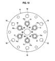
- the above embodiment has the communication holes 83 which penetrate from the bottoms of the annular grooves 11c recessed around the suction holes 11, but the communication holes 83 may be provided outside the annular grooves 11c like a modification of a valve plate 9 shown in Fig. 10 .
- Such a modification has larger interior space of the communication holes 83 than the above embodiment, but other than that, achieves the same effect as the above embodiment.
- the rotary valve 71 is rotatably and axially slidably fitted to the drive shaft 10 and is unrotatably and axially slidably connected to the stopper 73 so that the rotary valve 71 rotates with the drive shaft 10 as the rotary valve 71 is axially slidable with respect to the drive shaft.
- the rotary valve 71 may be axially slidably and unrotatably fitted to the drive shaft 10, without engaging with the stopper 73.
- the drive shaft 10 is provided with a slide guide portion having the same noncircular sectional shape as extending along the axial direction and the rotary valve 71 is provided with a fitting hole in which the slide guide portion is fitted, so that the rotary valve 71 can be axially slidably and unrotatably connected to the drive shaft 10.
- the sectional shapes of the slide guide portion and the fitting hole are a regular polygon (for example, right hexagon) or a spline shape, etc., the slide guide portion and the fitting hole are easy to fabricate.
- the above embodiment uses the swash plate (rotary cam plate 24); however the present invention can use a wobble plate (non-rotary cam plate).
- the swash plate 24 is directly attached to the drive shaft 10, but the swash plate 24 may attached to the drive shaft 10 via a sleeve.
- connection mechanism 40 is not limited to the configuration of the above embodiment.
Abstract
A compressor (1) includes communication holes (83) penetrating through a valve plate (9) at positions opposite to regulation steps of a cylinder block (2) and communicating cylinder bores (3) and suction chamber (7), a rotary valve (71) configured to rotate with the drive shaft (10) and be in rotational slide contact with a suction chamber side of the valve plate (9) as covering the communication holes (83) of the valve plate (9). The rotary valve (71) is formed with a residual pressure release passage (71c). As the rotary valve (71) rotates, the residual pressure release passage (71c) connects by turns one of the communication holes (83) communicating with one of the cylinder bores (3) having finished discharge and another of the communication holes (83) communicating with another of cylinder bores (3) having lower pressure than the one of the cylinder bores (3).
Description
- The present invention relates to a compressor.
- A compressor is disclosed in Japanese Patent Application Laid-Open No.
2005-163714 - The valve plate is formed with suction holes communicating the cylinder bore with the suction chamber and discharge holes communicating the cylinder bore with the discharge chamber. A reed type suction valve is provided at the cylinder bore side of the valve plate to open and close the suction holes. A reed type discharge valve is provided at the discharge chamber side of the valve plate to open and close the discharge holes.
- A piston is reciprocatably arranged in each cylinder bore. In the crank chamber, a conversion mechanism is provided to convert rotations of the drive shaft into reciprocations of the pistons. With this configuration, when the drive shaft rotates, the pistons reciprocate within the cylinder bores. When the pistons reciprocate, refrigerant is sucked into the cylinder bores from the suction chamber, and the sucked refrigerant is compressed in the cylinder bores and then discharged out from the cylinder bores into the discharge chamber.
- In general, even when the piston is located in the top dead center thereof, a small amount of high-pressure refrigerant remains in the cylinder bore since the refrigerant cannot completely be discharged out into the discharge chamber.
- Such a residual refrigerant is reexpanded in a suction stroke in which the piston moves from the top dead center to the bottom dead center. The reexpansion amount of the residual refrigerant reduces fresh refrigerant to be sucked through the suction holes from the suction chamber. As a result, the suction amount of the fresh refrigerant decreases and the suction efficiency decreases.
- Therefore, the above conventional art is configured such that the high-pressure residual gas which remained in one of the cylinder bores after a compression stroke is discharged to another of the cylinder bores having lower pressure than the one of the cylinder bores. In particular, communication holes are provided which radially extend through the cylinder block so as to connect the cylinder bores to the bearing hole rotatably supporting the drive shaft at the center of the cylinder block. Moreover, a residual-gas bypass passage is formed in a groove shape or in a hole shape on the outer peripheral surface of the drive shaft. As the drive shaft rotates, the residual-gas bypass passage connects one of the cylinder bores having finished a discharge stroke to another of the cylinder bores which has lower pressure than the one of the cylinder bores. In other words, the residual-gas bypass passage connects one of the communication holes which communicates with one of the cylinder bores having finished the discharge stroke to another of the communication holes which communicates with another of the cylinder bores having lower pressure than the one of the cylinder bores. Therefore, the high-pressure residual gas which remained in one of the cylinder bores at the end of the compression stroke can be released to another of the cylinder bores having lower pressure than the one of the cylinder bores.
- In the above-mentioned conventional compressor, since the communication holes are open at inner circumference surfaces of the cylinder bores, the communication holes have been required to be machined to prevent bad slide contacts between the inner circumference surfaces of the cylinder bores and outer circumference surfaces of the pistons. This requires high machining accuracy and the manufacturing cost tends to become more expensive.
- Moreover, communication holes that communicate the bearing hole provided at the center of the cylinder block with the cylinder bores provided around the bearing hole have comparatively large interior spaces so that the residual gas tend to easily remain in the communication holes.
- The present invention is invented based on such a conventional art, and the object of the present invention is to provide a compressor capable of obtain a good slide contact between inner circumference surface of cylinder bores and outer circumference surface of pistons even though a high-pressure residual gas release path is provided.
- An aspect of the present invention is a compressor including: a cylinder block formed with cylinder bores spaced from each other in an interval along a circumferential direction of the cylinder block around a drive shaft; a housing attached to the cylinder block via a valve plate through which suction holes are penetrated and forming a suction chamber therein; reed type suction valves disposed on a cylinder bore side of the valve plate and configured to open and close the suction holes, regulation steps recessed, at the periphery of the cylinder bore, from a valve plate side of the cylinder block and configured to limit maximum lift positions of the suction valves; pistons reciprocatably disposed in the cylinder bores respectively and configured to reciprocate with rotation of the drive shaft to perform an suction stroke and a discharge stroke by turns within the cylinder bores; communication holes penetrating through the valve plate at positions opposite to the regulation steps and connecting the cylinder bores and the suction chamber; and a rotary valve configured to be in rotational slide contact with the suction chamber side of the valve plate with covering the communication holes of the valve plate as rotating with the drive shaft; a residual pressure release passage formed in the rotary valve. As the rotary valve rotates, the residual pressure release passage sequentially connects one of the communication holes which communicates with one of the cylinder bores which has finished a discharge stroke and another of the communication holes which communicates with another of the cylinder bores which has a lower-pressure than the one of the cylinder bores.
-
- [
Fig. 1] Fig. 1 is a sectional view of a compressor according to an embodiment of the present invention. - [
Fig. 2] Fig. 2 is an expanded sectional view of a residual pressure release mechanism of the compressor. - [
Fig. 3] Fig. 3 is an exploded perspective view of the compressor, explaining a stacked structure including a suction valve plate, a valve plate and a rotary valve. - [
Fig. 4] Fig. 4 is an exploded perspective view of the residual pressure release mechanism, explaining an assembly of the valve plate, a stopper and a coil spring. - [
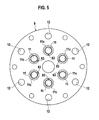
Fig. 5] Fig. 5 is a rear view of the valve plate. - [
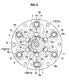
Fig. 6] Fig. 6 is a sectional view along SA-SA line inFig. 2 , explaining connecting states between the residual pressure release passage and communication holes as the rotary valve rotates, and particularly, showing a state before the connection. - [
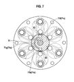
Fig. 7] Fig. 7 is a sectional view along SA-SA line inFig. 2 , explaining the connecting states between the residual pressure release passage and communication holes as the rotary valve rotates, and particularly, showing the connection state. - [
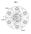
Fig. 8] Fig. 8 is a sectional view along SA-SA line inFig. 2 , explaining the connecting states between the residual pressure release passage and communication holes as the rotary valve rotates, and particularly, showing a state after the connection. - [
Fig. 9] Fig. 9 is a view of a rotary valve of a compressor according to a first modification. - [
Fig. 10] Fig. 10 is a view of a valve plate of a compressor according to a second modification. - [
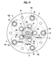
Fig. 11] Fig. 11 is a view of a valve plate and a rotary valve of a compressor according to a third modification. - Hereafter, compressors according to embodiments of the present invention will be explained with reference to drawings.
- First, an embodiment of the present invention will be explained with reference to
Figs. 1-8 . A discharge valve plate is omitted inFigs. 6 to 8 . - The
compressor 1 of the present embodiment is a swash plate type variable capacity compressor as shown inFig. 1 . Thiscompressor 1 has acylinder block 2 which has two ormore cylinder bores 3 spaced evenly apart from each other in a circumferential direction thereof, afront housing 4 which is attached to a front end of thecylinder block 2 and forms therein acrank chamber 5 communicating with thecylinder bore 3, arear housing 6 which is attached to a rear end of thecylinder block 2 with avalve plate 9 therebetween and forms therein asuction chamber 7 and adischarge chamber 8. The cylinder blocks 2, thefront housing 4 and therear housing 6 are attached and fastened together with throughbolts 13 so as to constitute an overall housing of the compressor. - Between the
valve plate 9 and therear housing 6, agasket 53 intervenes to maintain sealing of thesuction chamber 7 and thedischarge chamber 8. Between thevalve plate 9 and thecylinder block 2, a gasket 54 (seeFig. 2 ) intervenes to maintain sealing of thecylinder bore 3. - The
valve plate 9 is formed in an approximately circular disk shape. Thevalve plate 9 is formed withsuction holes 11 communicating thecylinder bores 3 with thesuction chamber 7, anddischarge holes 12 communicating thecylinder bores 3 with thedischarge chamber 8. - In the
suction chamber 7, a suction valve plate 55 (refer toFig. 3 ) having reedtype suction valves 57 to open and close thesuction holes 11 is provided on the front side of the valve plate 9 (the cylinder block side of the valve plate 9). In thedischarge chamber 8, adischarge valve plate 61 having reedtype discharge valves 63 to open and close thedischarge holes 12 is provided on the rear side of the valve plate 9 (the rear housing side of the valve plate 9). - The
suction valve plate 55 is formed as an elastic thin plate (for example, a metallic thin plate etc.) and is sandwiched between thevalve plate 9 and thecylinder block 2 as shown inFig. 1 . Thesuction valve plate 55 is formed with the reedtype suction valves 57 at positions corresponding to thesuction holes 11. Thesuction valves 57 normally cover and close thesuction holes 11. When pressure in the cylinder bore 3 declines in a suction stroke and a pressure difference between thesuction chamber 7 and thecylinder bore 3 becomes greater than predetermined level, thesuction valve 57 is flexurally deformed to open thesuction hole 11. Maximum lift positions of thesuction valves 57 are regulated by regulation steps 59 (seeFig. 2 ) which are recessed at peripheries of thecylinder bores 3 from the rear end of the cylinder block 2 (the side of thecylinder block 2 to which therear housing 6 is attached). On the other hand, thedischarge valve plate 61 is formed as an elastic thin plate (for example, a metallic thin plate etc.) and is sandwiched between thevalve plate 9 and therear housing 6 as shown inFig. 1 . Thedischarge valve plate 61 is formed with the reed thetype discharge valves 63 at positions corresponding to the discharge holes 12. Thedischarge valves 63 normally cover and close the discharge holes 12. In a compression stroke, thedischarge valve 63 is flexurally deformed so as to open thedischarge hole 12 when the inside of the cylinder bore 3 exceeds predetermined pressure. Maximum lift positions of thedischarge valves 63 are regulated bystopper parts 65 formed on thegasket 53. -
Annular grooves Figs. 5-6 ) are recessed around the suction holes 11 and the discharge holes 12 so as to decrease a contact area where thesuction valve 57 contacts with thevalve plate 9 and a contact area where thedischarge valve 63 contacts with thevalve plate 9, and therefore thesuction valve 57 and thedischarge valve 63 open easily. - The
drive shaft 10 is rotatably supported by center throughholes cylinder block 2 and thefront housing 4 viaradial bearings drive shaft 10 is rotatable in thecrank chamber 5. - The
thrust bearing 20 intervenes between an inner surface of thefront housing 4 and a front side of arotor 21 fixed to thedrive shaft 10 in thecrank chamber 5. Thethrust bearing 16 intervenes between a step portion formed on thedrive shaft 10 and theadjustable screw 17 fixed to the center throughhole 14 of thecylinder block 2. This configuration stops axial movements of the drive shaft. - In the
crank chamber 5, a conversion mechanism is provided to convert rotation of thedrive shaft 10 into reciprocation of thepistons 29. The conversion mechanism includes therotor 21 as a rotation member fixed to thedrive shaft 10, a swash plate slidably and inclinably attached to thedrive shaft 10, and aconnection mechanism 40 connecting therotor 21 and theswash plate 24 such that therotor 21 and theswash plate 24 rotate as one unit with permitting variation of the inclination angle of theswash plate 24. Thepistons 29 each is attached to an outer peripheral portion of theswash plate 24 with a pair ofhemispherical piston shoes swash plate 24 rotates, thepistons 29 reciprocate in the cylinder bores 3 according to the inclination angle of theswash plate 24. As thepistons 29 reciprocate, refrigerant is sucked from thesuction chamber 7 into the cylinder bores 3 through the suction holes 11 of thevalve plate 9, and compressed within the cylinder bores 3, and then the compressed refrigerant is discharged out into thedischarge chamber 8 through the discharge holes 12 of thevalve plate 9. - When the
swash plate 24 moves toward thecylinder block 2 against areturn spring 52, the inclination angle of theswash plate 24 decreases, and when theswash plate 24 moves away from thecylinder block 2 against areturn spring 51, the inclination angle of theswash plate 24 increases. - In order to change the refrigerant discharge capacity, the inclination angle of the
swash plate 24 is controlled to change the piston stroke. Based on a pressure difference (pressure balancing) between crank chamber pressure Pc at the rear side of thepiston 29 and suction chamber pressure Ps at the front side of thepiston 29, the inclination angle of theswash plate 24 is changed and the piston stroke is changed. Therefore, a pressure control mechanism is provided in the variable capacity compressor. The pressure control mechanism has a gas releasing passage (not shown) communicating thecrank chamber 5 with thesuction chamber 7 and a gas supplying passage (not shown) communicating thecrank chamber 5 with thedischarge chamber 8, and acontrol valve 33 provided in a middle of the gas supplying passage and configured to control to open and close the gas supplying passage. - Regardless of opening or closing of the
control valve 33, refrigerant gas is released from thecrank chamber 5 through the gas releasing passage into thesuction chamber 7. - When the
control valve 33 opens the gas supplying passage, high-pressure refrigerant gas flows from thedischarge chamber 8 into thecrank chamber 5 through the gas supplying passage, and thereby, the pressure in thecrank chamber 5 rises. As the pressure in thecrank chamber 5 rises, theswash plate 24 moves toward thecylinder block 2 and the inclination angle of theswash plate 24 decreases. Therefore, the piston stroke becomes small and the discharge amount of thecompressor 1 decreases. - On the other hand, when the
control valve 33 closes the gas supplying passage, the pressure difference between thesuction chamber 7 and thecrank chamber 5 reduces to be zero. Then, theswash plate 24 moves away from thecylinder block 2 to increase the inclination angle of the swash plate, the piston stroke becomes large and the discharge amount of thecompressor 1 increases. - Next, a residual
pressure release mechanism 70 will be explained. - The compressor of the present embodiment further includes communication holes 83 (
Figs. 2 ,3 ) formed in thevalve plate 9 at positions corresponding to the cylinder bores 3 and includes the residual pressure release mechanism 70 (Fig. 2 ) configured to connect and disconnect the communication holes 83 each other. The residualpressure release mechanism 70 is configured to release the high pressure residual gas which remained one of the cylinder bores 3 having finished discharge to another of the cylinder bores 3 having lower-pressure than the one of the cylinder bores 3 concerned. - The residual
pressure release mechanism 70 is provided on the rear side of the valve plate 9 (therear housing 6 side of the valve plate 9). The residualpressure release mechanism 70 is provided with arotary valve 71, astopper 73 and an elastic member (in this embodiment, acoil spring 75 as a spring). Therotary valve 71, thestopper 73 and thecoil spring 75 are arranged in thesuction chamber 7 as shown inFigs. 1 and2 . - The
rotary valve 71 is formed with acylindrical boss part 71a and amain part 71b outwardly extending from theboss part 71a and formed in a circular disk shape as shown inFigs. 2-4 . Theboss part 71a of therotary valve 71 is fitted around an outer circumferential surface of thedrive shaft 10 which extends through a center through hole 81 of thevalve plate 9 into thesuction chamber 7, so that the rotary valve can rotatably and axially slidably move with respect to thedrive shaft 10. Themain part 71b of therotary valve 71 is formed with a residualpressure release passage 71c formed in an arc slot shape and recessed on a slide contact surface where therotary valve 71 slidably contacts (Fig. 2-4 ). - The
stopper 73 is formed with acylindrical boss part 73a and aflange part 73b outwardly projected from theboss part 73a in a circular disk shape as shown inFigs. 2 and4 . Theboss part 73a of thestopper 73 is fixedly attached to anaxial end 10a of thedrive shaft 10 with thebolt 77 as a fastening means, so that thestopper 73 rotates withdrive shaft 10 together. As shown inFig. 4 , theaxial end 10a of thedrive shaft 10 is formed as a hexagon shapedfitting part 10a, and an inside of theboss part 73a of thestopper 73 is formed as a hexagon shapedfitting hole 73c into which thefitting part 10a of the drive shaft is fitted. - As shown in
Figs. 2 and4 , a pair ofarms 73d is projected from theboss part 73a of thestopper 73 towards theboss part 71a of therotary valve 71. Thearms 73d and theboss part 73a of the rotary valve have rotation transmission faces 71e and 73e respectively which carry out facing contact each other and transmit rotation of thestopper 73 to therotary valve 71. Thereby, therotary valve 71 and thedrive shaft 10 rotate as one unit with thestopper 73. - As shown in
Fig. 2 , thecoil spring 75 is compressed between theflange part 73b of thestopper 73 and themain part 71b of therotary valve 71. Thereby, therotary valve 71 is biased toward thevalve plate 9 so as to be in close contact with thevalve plate 9. - When the
rotary valve 71 which is in close contact with thevalve plate 9 rotates with thedrive shaft 10, the residualpressure release passage 71c on therotary valve 71 rotates, and thereby, connections occur sequentially between one of the communication holes 83 which communicates with one of the cylinder bores 3 having finished a compression stroke (a discharge stroke) and another of the communication holes 83 which communicates with another of the cylinder bores 3 having lower-pressure than the one of the cylinder bores 3. - In particular, the
valve plate 9 is formed with the communication holes 83 provided at positions facing to the regulation steps 59 of the cylinder bores 3. The residualpressure release passage 71c includes aninlet port 71f, anoutlet port 71 h, and aconnection part 71 g connecting theinlet port 71 f and theoutlet port 71 h. The communication holes 83 are located on rotational tracks of theinlet port 71f and theoutlet port 71h but out of a rotational track of theconnection part 71g. - With this configuration, as the
rotary valve 71 rotates, theinlet port 71f of the residualpressure release passage 71c connects with thecommunication hole 83 of one of the cylinder bores 3 having finished a compression stroke one by one, and theoutlet port 71h of thepassage 71c connects with thecommunication hole 83 of another of the cylinder bore 3 having lower-pressure than the one of the cylinder bores 3 one by one. Therefore, the high-pressure residual gas remaining in one of the cylinder bore 3 which has finished a discharge stroke flows into another of the cylinder bores 3 having lower-pressure than the one of the cylinder bores 3. - In this embodiment, the communication holes 83 of the
valve plate 9 are penetrated from the bottoms of theannular grooves 11c which are formed around the suction holes 11. - Next, effects of this embodiment will be explained.
- The
compressor 1 of this embodiment includes the communication holes 83 extending through thevalve plate 9 at the positions opposite to the regulation steps 59 of the cylinder bores 3 and connecting the cylinder bores 3 and thesuction chamber 7, and therotary valve 71 configured to rotate with thedrive shaft 10 with covering thecommunication hole 83 of thevalve plate 9 and be in rotational slide contact with the suction chamber side of thevalve plate 9. Therotary valve 71 is formed with the residualpressure release passage 71c. As therotary valve 71 rotates, the residualpressure release passage 71c interconnects by turns one of communication holes 83 of the valve plate communicating with one of the cylinder bores 3 having finished discharge and another of the communication holes 83 of the valve plate communicating with another of the cylinder bores 83 having lower pressure than the one of the cylinder bores having finished discharge. - Therefore, the high pressure residual gas which remained in the one of the cylinder bores 3 without being discharged out in a compression stroke thereof escapes from the one of the cylinder bores 3 (that is, a
cylinder bore 3 in an early stage of a suction stroke) into another of the cylinder bores 3 having lower-pressure than the one of the cylinder bores 3 concerned (that is, acylinder bore 3 in a early stages or a middle stage of a compression stroke). Thus, the reexpansion of the high pressure residual gas decreases in a suction stroke, and the suction efficiency improves. - Unlike the above-mentioned conventional art (for example,
JP2005-163714 piston 29 can be obtained. - Moreover, since the
communication hole 83 of thevalve plate 9 extends through thevalve plate 9, the inside space of thecommunication hole 83 tends to be smaller than the conventional art (for example,JP2005-163714 - Furthermore, since the communication holes 83 of the
valve plate 9 are provided at the positions opposite to the regulation steps 59, this configuration allows to use spaces 85 between the regulation steps 59 and thevalve plate 9. - Moreover, in the
compressor 1 of this embodiment, theannular grooves 11c are formed around the suction holes 11 on the front side of the valve plate 9 (the cylinder bore 3 side of the valve plate 9). - With the
annular grooves 11c, thesuction valves 57 easily open, and the suction efficiency further improves. And since the communication holes 83 are provided at theannular grooves 11c of the valve plates 9 (i.e., since the communication holes 83 are provided in thin portions of the valve plate 9), length of the communication holes 83 become small. Therefore, the suction efficiency further improves because the inside spaces of the communication holes 83 becomes smaller and dead volume becomes smaller. - The
compressor 1 of the embodiment has the through hole 81 of thevalve plate 9 to allow thedrive shaft 10 extend into thesuction chamber 7, so that therotary valve 71 is directly or indirectly connected to thedrive shaft 10 in thesuction chamber 7 to rotate with thedrive shaft 10. - Therefore, the
rotary valve 71 and thedrive shaft 10 rotates together with such a simple structure. - In the
compressor 1 of this embodiment, thestopper 73 is provided which is fixed to thedrive shaft 10 and configured to rotate with thedrive shaft 10 in thesuction chamber 7, and therotary valve 71 is axially slidably and rotatably fitted to thedrive shaft 10 and axially slidably and unrotatably connected to thestopper 73 such that therotary valve 71 and thedrive shaft 10 rotates as one unit. And therotary valve 71 is biased towards thevalve plate 9 by theelastic member 75 compressed between thestopper 73 and therotary valve 71. - Therefore, the
rotary valve 71 is in close contact to thevalve plate 9 firmly. With this, the compression efficiency improves because the high pressure compression medium compressed within the cylinder bores 3 hardly leaks from the suction holes 11 of the cylinder bores 3, through clearance between thevalve plate 9 and therotary valve 71, into thesuction chamber 7. - If the pressure in the cylinder bore 3 goes up extremely high, the
rotary valve 71 lift up away from thevalve plate 9, and the superfluous pressure in the cylinder bore 3 can be released out into thesuction chamber 7. Therefore, the safety of thecompressor 1 improves. - Moreover, the
coil spring 75 does not touch therear housing 6, so that vibration of therotary valve 71 is prevented from being transmitted to therear housing 6 through thecoil spring 75. Thereby, thecompressor 1 of this embodiment improves the vibration suppression. - In the embodiment, the
stopper 73 of thecoil spring 75 rotates with therotary valve 71, it is unnecessary to provide a thrust bearing between the coil spring and the stopper or between the coil spring and the rotary valve. This brings about low cost manufacturing because such an expensive thrust bearing is unnecessary. - The present invention is not limited only to the embodiment described above.
- For example, the above embodiment has the residual pressure release passage which has one inlet port and one outlet port, but the residual pressure release passage may have two or
more outlet ports 71h-1 and 71h-2 such as a modification shown inFig. 9 . According to the first modification, it is advantageous that the timing for releasing the residual pressure can be made in varieties. - The above embodiment has the communication holes 83 which penetrate from the bottoms of the
annular grooves 11c recessed around the suction holes 11, but the communication holes 83 may be provided outside theannular grooves 11c like a modification of avalve plate 9 shown inFig. 10 . Such a modification has larger interior space of the communication holes 83 than the above embodiment, but other than that, achieves the same effect as the above embodiment. - Even though the above embodiment has six cylinder bores 3, a modification shown in
Fig. 11 which has five cylinder bores 3 or other number of the cylinder bores will have the same effect as or similar effect to the above embodiment. - In the above embodiment, the
rotary valve 71 is rotatably and axially slidably fitted to thedrive shaft 10 and is unrotatably and axially slidably connected to thestopper 73 so that therotary valve 71 rotates with thedrive shaft 10 as therotary valve 71 is axially slidable with respect to the drive shaft. In the present invention, therotary valve 71 may be axially slidably and unrotatably fitted to thedrive shaft 10, without engaging with thestopper 73. For example, in case of directly transmitting the rotation of adrive shaft 10 to arotary valve 71 without astopper 73, thedrive shaft 10 is provided with a slide guide portion having the same noncircular sectional shape as extending along the axial direction and therotary valve 71 is provided with a fitting hole in which the slide guide portion is fitted, so that therotary valve 71 can be axially slidably and unrotatably connected to thedrive shaft 10. If the sectional shapes of the slide guide portion and the fitting hole are a regular polygon (for example, right hexagon) or a spline shape, etc., the slide guide portion and the fitting hole are easy to fabricate. - The above embodiment uses the swash plate (rotary cam plate 24); however the present invention can use a wobble plate (non-rotary cam plate).
- In the above embodiment, the
swash plate 24 is directly attached to thedrive shaft 10, but theswash plate 24 may attached to thedrive shaft 10 via a sleeve. - The
connection mechanism 40 is not limited to the configuration of the above embodiment. - The present invention can be implemented with various other modifications without departing from technical scope of the present invention.
Claims (5)
- A compressor, comprising:a cylinder block formed with cylinder bores spaced away each other in an interval in a circumferential direction of the cylinder block around a drive shaft;a housing attached to the cylinder block via a valve plate and forming a suction chamber therein, the valve plate formed with suction holes penetrating therethrough;reed type suction valves arranged on a cylinder bore side of the valve plate and configured to open and close the suction holes; regulation steps provided at peripheries of the cylinder bores and recessed from a side of the cylinder block where the valve plate is attached, the regulation steps configured to limit maximum lift positions of the suction valves;pistons configured to reciprocate in the cylinder bores as the drive shaft rotates so as to carry out a suction stroke and a discharge stroke by turns in the cylinder bores;communication holes penetrating through the valve plate at positions opposite to the regulation steps, the communication holes communicating the cylinder bores and the suction chamber; a rotary valve configured to rotate with the drive shaft and be in rotational slide contact with a suction chamber side of the valve plate with covering the communication holes of the valve plate; anda residual pressure release passage configured to connect one of the communication holes communicating with one of the cylinder bores having finished discharge and another of the communication holes communicating with another of cylinder bores having lower pressure than the one of the cylinder bores by turns, as the rotary valve rotates.
- The compressor according to Claim 1, wherein
annular grooves are formed around the suction holes on the cylinder bore side of the valve plate, and the communication holes are formed in the annular grooves. - The compressor according to Claim 1, wherein
the residual pressure release passage is formed with two or more outlet ports. - The compressor according to Claim 1, wherein
the drive shaft extends into the suction chamber through a through hole extending through the valve plate, and the rotary valve is directly or indirectly connected to the drive shaft so as to rotate with the drive shaft together. - The compressor according to Claim 4, further comprising
a stopper fixed to the drive shaft so as to rotate with the drive shaft in the suction chamber,
wherein the rotary valve is axially slidably and rotatably fitted to the drive shaft and is axially slidably and unrotatably fitted to the stopper so that the rotary valve rotates with the drive shaft, and wherein the rotary valve is biased toward the valve plate by the elastic member compressed between the stopper and the rotary valve.
Applications Claiming Priority (2)
| Application Number | Priority Date | Filing Date | Title |
|---|---|---|---|
| JP2006203061A JP2008031857A (en) | 2006-07-26 | 2006-07-26 | Compressor |
| PCT/JP2007/064486 WO2008013162A1 (en) | 2006-07-26 | 2007-07-24 | Compressor |
Publications (1)
| Publication Number | Publication Date |
|---|---|
| EP2045465A1 true EP2045465A1 (en) | 2009-04-08 |
Family
ID=38981473
Family Applications (1)
| Application Number | Title | Priority Date | Filing Date |
|---|---|---|---|
| EP07791218A Withdrawn EP2045465A1 (en) | 2006-07-26 | 2007-07-24 | Compressor |
Country Status (6)
| Country | Link |
|---|---|
| US (1) | US20100003145A1 (en) |
| EP (1) | EP2045465A1 (en) |
| JP (1) | JP2008031857A (en) |
| KR (1) | KR20090031953A (en) |
| CN (1) | CN101495751A (en) |
| WO (1) | WO2008013162A1 (en) |
Cited By (1)
| Publication number | Priority date | Publication date | Assignee | Title |
|---|---|---|---|---|
| CN111794943A (en) * | 2020-06-05 | 2020-10-20 | 广州万宝集团压缩机有限公司 | Compressor cylinder head assembly, compressor and refrigeration equipment |
Families Citing this family (4)
| Publication number | Priority date | Publication date | Assignee | Title |
|---|---|---|---|---|
| JP2011085029A (en) * | 2009-10-13 | 2011-04-28 | Calsonic Kansei Corp | Compressor |
| US10852040B2 (en) * | 2015-07-23 | 2020-12-01 | Korea Institute Of Machinery & Materials | Linear expander and cryogenic refrigeration system including the same |
| CN105952622B (en) * | 2016-06-03 | 2018-07-27 | 江苏盈科汽车空调有限公司 | A kind of spring-piece type valve board assembly |
| CN106168214A (en) * | 2016-06-29 | 2016-11-30 | 珠海格力节能环保制冷技术研究中心有限公司 | A kind of cylinder that turns increases enthalpy piston compressor and has its air conditioning system |
Family Cites Families (4)
| Publication number | Priority date | Publication date | Assignee | Title |
|---|---|---|---|---|
| JP3079743B2 (en) * | 1992-02-21 | 2000-08-21 | 株式会社豊田自動織機製作所 | Refrigerant gas suction structure in piston type compressor |
| JPH0861239A (en) * | 1994-08-16 | 1996-03-08 | Toyota Autom Loom Works Ltd | Refrigerant gas suction structure of piston type compressor |
| JP4910184B2 (en) * | 2000-06-20 | 2012-04-04 | 株式会社ヴァレオジャパン | Reciprocating refrigerant compressor |
| JP2005163714A (en) | 2003-12-04 | 2005-06-23 | Toyota Industries Corp | Piston type compressor |
-
2006
- 2006-07-26 JP JP2006203061A patent/JP2008031857A/en not_active Withdrawn
-
2007
- 2007-07-24 EP EP07791218A patent/EP2045465A1/en not_active Withdrawn
- 2007-07-24 US US12/374,947 patent/US20100003145A1/en not_active Abandoned
- 2007-07-24 CN CNA2007800281304A patent/CN101495751A/en active Pending
- 2007-07-24 KR KR1020097003956A patent/KR20090031953A/en not_active Application Discontinuation
- 2007-07-24 WO PCT/JP2007/064486 patent/WO2008013162A1/en active Application Filing
Non-Patent Citations (1)
| Title |
|---|
| See references of WO2008013162A1 * |
Cited By (2)
| Publication number | Priority date | Publication date | Assignee | Title |
|---|---|---|---|---|
| CN111794943A (en) * | 2020-06-05 | 2020-10-20 | 广州万宝集团压缩机有限公司 | Compressor cylinder head assembly, compressor and refrigeration equipment |
| CN111794943B (en) * | 2020-06-05 | 2021-11-12 | 广州万宝集团压缩机有限公司 | Compressor cylinder head assembly, compressor and refrigeration equipment |
Also Published As
| Publication number | Publication date |
|---|---|
| JP2008031857A (en) | 2008-02-14 |
| KR20090031953A (en) | 2009-03-30 |
| CN101495751A (en) | 2009-07-29 |
| US20100003145A1 (en) | 2010-01-07 |
| WO2008013162A1 (en) | 2008-01-31 |
Similar Documents
| Publication | Publication Date | Title |
|---|---|---|
| JP2007239722A (en) | Variable displacement reciprocating compressor | |
| US5562425A (en) | Gas suction structure in piston type compressor | |
| EP2045465A1 (en) | Compressor | |
| EP0809024B1 (en) | Reciprocating pistons of piston type compressor | |
| JP5065120B2 (en) | Reciprocating compressor | |
| US20100021318A1 (en) | Compressor | |
| EP2354548B1 (en) | Variable displacement type reciprocating compressor | |
| US6109883A (en) | Coupling construction of compressor housing and method for manufacturing compressor | |
| US20150260175A1 (en) | Variable displacement swash plate type compressor | |
| CN101334016A (en) | Compressor | |
| US5947698A (en) | Piston type compressor | |
| US8215924B2 (en) | Oil separating structure of variable displacement compressor | |
| JP4630801B2 (en) | Compressor | |
| US20120201697A1 (en) | Oil management system for a compressor | |
| JP4728097B2 (en) | Compressor | |
| JP2008111338A (en) | Compressor | |
| JP3082480B2 (en) | Refrigerant gas suction structure in piston type compressor | |
| EP2816230A2 (en) | Variable displacement swash plate type compressor | |
| KR20150060199A (en) | Reciprocating compressor | |
| JP2008184959A (en) | Compressor | |
| JP2014125994A (en) | Piston type compressor | |
| KR100715261B1 (en) | Variable displacement swash plate type compressor | |
| KR102006341B1 (en) | Variable displacement swash plate type compressor | |
| KR101336436B1 (en) | Piston for swash plate type compressor | |
| KR20190124673A (en) | Reciprocating compressor |
Legal Events
| Date | Code | Title | Description |
|---|---|---|---|
| PUAI | Public reference made under article 153(3) epc to a published international application that has entered the european phase |
Free format text: ORIGINAL CODE: 0009012 |
|
| 17P | Request for examination filed |
Effective date: 20090129 |
|
| AK | Designated contracting states |
Kind code of ref document: A1 Designated state(s): DE FR GB |
|
| AX | Request for extension of the european patent |
Extension state: AL BA HR MK RS |
|
| STAA | Information on the status of an ep patent application or granted ep patent |
Free format text: STATUS: THE APPLICATION HAS BEEN WITHDRAWN |
|
| 18W | Application withdrawn |
Effective date: 20100921 |