EP2045136B1 - Support de pince - Google Patents
Support de pince Download PDFInfo
- Publication number
- EP2045136B1 EP2045136B1 EP08016815A EP08016815A EP2045136B1 EP 2045136 B1 EP2045136 B1 EP 2045136B1 EP 08016815 A EP08016815 A EP 08016815A EP 08016815 A EP08016815 A EP 08016815A EP 2045136 B1 EP2045136 B1 EP 2045136B1
- Authority
- EP
- European Patent Office
- Prior art keywords
- fixture
- per
- section
- pin
- spacer
- Prior art date
- Legal status (The legal status is an assumption and is not a legal conclusion. Google has not performed a legal analysis and makes no representation as to the accuracy of the status listed.)
- Not-in-force
Links
Images



Classifications
-
- B—PERFORMING OPERATIONS; TRANSPORTING
- B60—VEHICLES IN GENERAL
- B60R—VEHICLES, VEHICLE FITTINGS, OR VEHICLE PARTS, NOT OTHERWISE PROVIDED FOR
- B60R3/00—Arrangements of steps or ladders facilitating access to or on the vehicle, e.g. running-boards
- B60R3/005—Catwalks, running boards for vehicle tops, access means for vehicle tops; Handrails therefor
-
- F—MECHANICAL ENGINEERING; LIGHTING; HEATING; WEAPONS; BLASTING
- F16—ENGINEERING ELEMENTS AND UNITS; GENERAL MEASURES FOR PRODUCING AND MAINTAINING EFFECTIVE FUNCTIONING OF MACHINES OR INSTALLATIONS; THERMAL INSULATION IN GENERAL
- F16B—DEVICES FOR FASTENING OR SECURING CONSTRUCTIONAL ELEMENTS OR MACHINE PARTS TOGETHER, e.g. NAILS, BOLTS, CIRCLIPS, CLAMPS, CLIPS OR WEDGES; JOINTS OR JOINTING
- F16B2/00—Friction-grip releasable fastenings
- F16B2/02—Clamps, i.e. with gripping action effected by positive means other than the inherent resistance to deformation of the material of the fastening
- F16B2/06—Clamps, i.e. with gripping action effected by positive means other than the inherent resistance to deformation of the material of the fastening external, i.e. with contracting action
- F16B2/065—Clamps, i.e. with gripping action effected by positive means other than the inherent resistance to deformation of the material of the fastening external, i.e. with contracting action using screw-thread elements
Definitions
- the invention relates to a device for fastening a walk-in plate according to the preamble of claim 1.
- a built support frame for a motor vehicle in particular a commercial vehicle is known, which has two side members, which are interconnected via at least one cross member.
- the longitudinal members each consist of a top flange and a bottom flange, as well as at least one vertical web connecting the top flange to the bottom flange.
- At least one longitudinal portion of the support frame is formed as a stiffening portion, the two webs and two cross members, namely an upper cross member and a lower cross member are assigned.
- the upper cross member is connected on the one hand with the upper flange and the web of a longitudinal member and on the other hand with the upper flange and the web of the other longitudinal member.
- the lower cross member is connected on the one hand to the lower flange and the web of a longitudinal member and on the other hand to the lower flange and the web of the other longitudinal member.
- the platform which includes a walkway accessible to the motor vehicle driver when the commercial vehicle is stopped. Desirable and required according to DIN 1726 is because of the required in particular for semi-trailer trains semitrailer clearance a low catwalk top.
- the fastening device is screwed to the catwalk at least 4 places on the top chord.
- the fastening device is thereby positioned on the underside of the catwalk so that the threaded connection is arranged on the longitudinal members on the inner side of the outer edge of the longitudinal member and spaced therefrom when the catwalk is resting on the longitudinal members.
- the outer edge of the longitudinal member points to the vehicle center.
- the lower part of the fastening device is in a position approximately parallel to the outer edge of the upper belt.
- the external thread of the pin of the lower part engages in the internal thread of the bore of the upper part.
- Pins and holes form a mating with clearance for a smooth axial-axial feed of the pin in the bore of the upper part.
- the lower part performs a lifting movement and passes from an open position in which the upper belt facing side of the lower part is axially spaced from the upper chord, in the closed position in which the lower part abuts with its upper belt side facing the underside of the upper flange in the clamping fit. Due to the spiral movement of the lower part relative to the upper part and the arrangement of the screw connection outside the outer edge of the upper belt can under the lower edge of the upper belt communication carrier such. B. electrical and compressed air lines along. There is no danger that due to the Hubschwenk Gay of the lower part relative to the upper belt from the open position to the closed position accidentally electric cables that are in protective tubes or pneumatic lines are on or jammed.
- the fastening device according to the invention is captively fastened to the catwalk.
- the catwalk is placed in conjunction with the fasteners on the / the upper straps. By pivoting the lower part in the closed position, the captive connection of the catwalk with the upper flange.
- the fastening device according to the invention is not limited to the attachment of the catwalk to the upper straps of the two frame rails of the truck, but can also be used for attachment of other parts of the commercial vehicle. Characterized in that the catwalk is provided with a hole pattern having a plurality of holes, the fastening device can be arranged at each required point of the catwalk and this be attached at different locations on the upper flange.
- the lower part is spaced from the upper flange by means of a lower spacer.
- an upper spacer is anchored in the upper part, which distances the catwalk from the upper flange.
- Another embodiment of the invention provides that a screw passes through a hole pattern bore of the catwalk and engages in a threaded bore of the upper spacer.
- the upper part is connected to the catwalk.
- the lower part is supported in the closed position outside the outer edge of the upper flange with a shoulder relative to the upper part.
- the shoulder can be arranged either on the lower part or on the upper part. The shoulder allows that when the closed position is reached by the lower part, the fastening device remains in the captive clamping seat on the upper flange.
- flank angle of the external thread of the pin is greater than the flank angle of the clamping screw.
- the external thread of the pin on a lubricity of the threads increasing coating is a Teflon coating.
- FIG. 1 shows the fastening device with an upper part 4, and a lower part 5, which are interconnected by a screw 19.
- the fastening device shown in the figure is in the closed position 11 and is fixed in a clamping fit on the upper flange 2 of the longitudinal frame member 3.
- the lower part 5 with its upper belt 2 side facing in abutment with the underside of the upper belt 2.
- the outer edge of the upper belt 2 is denoted by reference numeral 7.
- the upper part 4 has a recess 22 in which an upper spacer 13 is anchored, which distances the catwalk 1 (not shown) from the upper flange 2.
- a threaded bore 20 is shown, which serves to engage a screw 14, which penetrates one of the hole pattern holes 15 of the catwalk 1 and with the help of the catwalk 1 is secured captive on the upper part 4 of the fastening device.
- the screw head 23 of the clamping screw 6 In the region of the recess 22 of the upper part 4, which projects beyond the outer edge 7, the screw head 23 of the clamping screw 6 can be seen.
- the clamping screw 6 extends approximately at right angles to the outer edge 7 of the upper flange 2 and passes through the bore 9 of the upper part 4 and the pin 8 of the lower part 5.
- annular screw head support 24 is shown with which the clamping screw. 6 the upper part 4 engages behind.
- the shoulder 17 is supported outside the outer edge 7 of the lower part 5 relative to the upper part 4 from.
- the shoulder 17 is connected to the lower part 5 and corresponds in thickness approximately to the thickness of the upper belt 2.
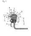
- FIG. 2 shows the section through the arranged in the press fit on the upper flange 2 fastening device according to the section line CC of FIG. 1 ,
- the sectional drawing in FIG. 2 is opposite the FIG. 1 reversed.
- the hole pattern holes 15 are shown, one of which is penetrated by a screw 14 which engages in a threaded bore 20 of the upper spacer 13.
- the upper spacer 13 is divided into two and has an upper spacer 38 which can be different thickness and with the help of the distance between the upper part 4 and catwalk 1 is adjustable. About the thickness of the spacer 38, the distance between the catwalk 1 and the bottom of the trailer is adjustable.
- the upper spacer 13 has a lower spacer 39, which ensures a safe removal anchorage 25 of the upper spacer 13 in the upper part 4 and at the same time serves as an elastic spacer to the upper flange.
- the lower spacer 39 protrudes from the plane of the underside 34 of the upper part 4 and distances the bottom 34 in the closed position 11 from the top 21 of the upper flange 2.
- an elastic lower spacer 18 is arranged in the lower part 5, the like the upper spacer 13 is made of rubber and the underside of the upper belt 2 from the top 26 of the lower part 5 distanced.
- the screw 19 is shown, which includes the pin 8 with the bore 9 of the upper part 4 in engagement and the clamping screw 6.
- the fastening device is shown in the closed position 11, in extension of the longitudinal axis 27 of the clamping screw 6 is a tool 28 z.
- a shoulder 17 can be seen, the free height of which corresponds approximately to the thickness of the upper belt 2.
- a lock nut 30 is seated at the side facing away from the upper flange 2 in the lower part 5 and is penetrated by the clamping screw 6.
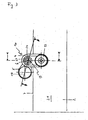
- FIG. 3 shows in plan view, which rests on the upper side 21 of the upper flange 2 upper part 4 with an upper spacer 13 and a screw head 23 and a screw head pad 24 of the clamping screw 6. Axial below the screw head 23 is the screw 19.
- the fastening device is in FIG. 3 shown in the open position 10, so that the lower part 5 comes to rest with the lower spacer 18 approximately parallel to the outer edge 7 of the upper belt 2.
- the section lines BB and AA are drawn, in the in the Figures 5 and FIG. 4 is referred to.
- FIG. 4 shows the section through the fastening device along the section line AA FIG. 3 ,
- the fastening device according to the invention is shown in the open position 10, wherein the upper part 4 and the lower part 5 are arranged approximately at an angle> 90 ° to each other.
- FIG. 4 is anchored in the upper part 4 upper spacer 13 recognizable.
- On the upper spacer 13 sits a threaded plate 31, which forms the bearing 32 of the threaded bore 20 and the upper spacer 13 of the upper part 4 laterally partially overlaps.
- the pin 8 as far out of the hole 9, as it allows the length of the clamping screw 6, without changing the contact with the lock nut 30 in the extent that she holds him in the closed position.
- the lock nut 30 is seated in a press fit in a recess 29 of the lower part 5.
- Die FIG. 4 shows that even in the open position 10 of the fastening device, the clamping screw 6 passes through the pin 8 of the lower part 5, wherein the pin 8 engages in comparison to the closed position 11 only in a relatively small extent in the bore 9 of the upper part 4.
- the cohesion of the upper part 4 and the lower part 5 is effected by the screw 19.
- the screw head pad 24 of the screw head 23 and the lock nut 30 anchor the screw 19 on the clamping screw. 6
- FIG. 5 shows the section through the fastening device according to the section lines BB of FIG. 3 ,
- the fastening device is in the open position 10, wherein the pin 8 of the lower part 5 comparable to FIG. 4 engages in the bore 9 of the upper part 4 in a small extent compared to the closed position 11.
- the upper part 4 has on its underside 34 an axial extension 33, in which the bore 9 extends and which corresponds approximately to the depth of recess 29 in the axial extent.
- the recess 22 of the upper part 4 serves to receive the screw head 23 and the screw head support 24 of the clamping screw 6.
- FIG. 2 and FIG. 5 it will be seen that upon reaching the closed position 11 (see FIG.
Landscapes
- Engineering & Computer Science (AREA)
- General Engineering & Computer Science (AREA)
- Mechanical Engineering (AREA)
- Clamps And Clips (AREA)
- Cutting Tools, Boring Holders, And Turrets (AREA)
- Gripping On Spindles (AREA)
- Tents Or Canopies (AREA)
Claims (9)
- Dispositif destiné à fixer une plaque accessible à pied (1), en particulier une plate-forme, sur les semelles supérieures (2) d'un longeron de cadre (3) d'un châssis de camion avec une partie supérieure (4) reposant sur la semelle supérieure (2) et portant la plaque (1) et une partie inférieure (5) appliquée par le dessous contre la semelle supérieure (2), les deux parties étant serrées l'une contre l'autre au moyen d'une vis de serrage (6), caractérisé en ce qu'un assemblage vissé (19) est disposé en dehors d'un bord extérieur (7) de la semelle supérieure (2) et qu'un tenon (8) est disposé sur la partie inférieure (5), qui présente un filetage (16) grâce auquel il peut être vissé lors du serrage de la vis de serrage (6) dans un taraudage (12) d'un alésage (9) de la partie supérieure (4) et la partie inférieure (5) peut être pivotée simultanément à partir d'une position d'ouverture (10) à côté de la semelle supérieure (2) dans une position de fermeture (11) dans laquelle la position de la partie inférieure (5) coïncide à peu près avec celle de la partie supérieure (4) reposant sur la semelle supérieure (2) et en ce que la vis de serrage (6) traverse le tenon (8) et est appliquée par derrière contre la partie supérieure (4).
- Dispositif selon la revendication 1, caractérisé en ce que la partie inférieure (5) est écartée de la semelle supérieure (2) au moyen d'un écarteur inférieur (18).
- Dispositif selon la revendication 1, caractérisé en ce qu'un écarteur supérieur (13) est ancré dans la partie supérieure (4) et assure l'écartement de la plaque (1) par rapport à la semelle supérieure (2).
- Dispositif selon la revendication 3, caractérisé en ce qu'une vis (14) traverse un gabarit de trous (15) de la plaque (1) et se visse dans un taraudage de l'écarteur supérieur (13) de la partie supérieure (4).
- Dispositif selon la revendication 1, caractérisé en ce que la partie supérieure (4) est reliée à la plaque (1).
- Dispositif selon la revendication 1, caractérisé en ce qu'en position de fermeture (11), la partie inférieure (5) est appuyée, en dehors du bord extérieur (7), contre la partie supérieure (4) au moyen d'une épaule (17).
- Dispositif selon la revendication 6, caractérisé en ce que la hauteur libre de l'épaule (17) est à peu près identique à l'épaisseur de la semelle supérieure (2).
- Dispositif selon la revendication 1, caractérisé en ce que l'angle du filet du filetage (16) du tenon (8) est supérieur à l'angle du filet de la vis de serrage (6).
- Dispositif selon la revendication 1, caractérisé en ce que le filetage (16) du tenon (8) est pourvu d'un revêtement améliorant la capacité de glissement des pas de filetage.
Priority Applications (1)
| Application Number | Priority Date | Filing Date | Title |
|---|---|---|---|
| PL08016815T PL2045136T3 (pl) | 2007-10-05 | 2008-09-25 | Zacisk mocujący |
Applications Claiming Priority (1)
| Application Number | Priority Date | Filing Date | Title |
|---|---|---|---|
| DE102007047777A DE102007047777A1 (de) | 2007-10-05 | 2007-10-05 | Klemmhalter |
Publications (2)
| Publication Number | Publication Date |
|---|---|
| EP2045136A1 EP2045136A1 (fr) | 2009-04-08 |
| EP2045136B1 true EP2045136B1 (fr) | 2010-01-20 |
Family
ID=40228039
Family Applications (1)
| Application Number | Title | Priority Date | Filing Date |
|---|---|---|---|
| EP08016815A Not-in-force EP2045136B1 (fr) | 2007-10-05 | 2008-09-25 | Support de pince |
Country Status (4)
| Country | Link |
|---|---|
| EP (1) | EP2045136B1 (fr) |
| AT (1) | ATE455677T1 (fr) |
| DE (2) | DE102007047777A1 (fr) |
| PL (1) | PL2045136T3 (fr) |
Family Cites Families (5)
| Publication number | Priority date | Publication date | Assignee | Title |
|---|---|---|---|---|
| US1327011A (en) * | 1919-06-14 | 1920-01-06 | Franklin E Arndt | Clamp for burial-vaults |
| US2227873A (en) * | 1939-01-23 | 1941-01-07 | Universal Railway Devices Comp | Running board |
| DE1400882A1 (de) * | 1963-10-19 | 1968-11-14 | Pohlig Heckel Bleichert | Klemmplatte mit durch diese gefuehrter Spannschraube |
| US3731967A (en) * | 1971-08-25 | 1973-05-08 | Sealed Unit Services Inc | Roof walkway for truck cabs |
| DE10137379A1 (de) | 2001-07-31 | 2003-02-27 | Daimler Chrysler Ag | Gebauter Tragrahmen für ein Kraftfahrzeug |
-
2007
- 2007-10-05 DE DE102007047777A patent/DE102007047777A1/de not_active Withdrawn
-
2008
- 2008-09-25 DE DE502008000334T patent/DE502008000334D1/de active Active
- 2008-09-25 PL PL08016815T patent/PL2045136T3/pl unknown
- 2008-09-25 AT AT08016815T patent/ATE455677T1/de active
- 2008-09-25 EP EP08016815A patent/EP2045136B1/fr not_active Not-in-force
Also Published As
| Publication number | Publication date |
|---|---|
| ATE455677T1 (de) | 2010-02-15 |
| DE502008000334D1 (de) | 2010-03-11 |
| PL2045136T3 (pl) | 2010-06-30 |
| DE102007047777A1 (de) | 2009-04-09 |
| EP2045136A1 (fr) | 2009-04-08 |
Similar Documents
| Publication | Publication Date | Title |
|---|---|---|
| EP2142428B1 (fr) | Dispositif servant a fixer des objets | |
| DE19542109A1 (de) | Befestigungsanordnung einer Reling auf einem Fahrzeugdach | |
| EP0754595B1 (fr) | Système variable de fixation rapide d?un coffre de toit sur les transverses d'une galerie de toit | |
| DE102007034432B4 (de) | Schalungselement für Rundschalungen | |
| EP1213161A2 (fr) | Dispositif de traction de remorque | |
| EP2045136B1 (fr) | Support de pince | |
| DE102007056471B4 (de) | Profilschiene für Ladungssicherungssysteme | |
| EP3882083A1 (fr) | Dispositif abaissable de support pour marchandises à transporter, ensemble et procédé de montage | |
| DE102022105559B3 (de) | Hebe-und Transportvorrichtung | |
| DE3516483C2 (fr) | ||
| EP2900535B1 (fr) | Console permettant de relier à un véhicule ferroviaire des superstructures de toit | |
| EP2953828A1 (fr) | Dispositif de support muni d'une unité de montage | |
| DE10332507B4 (de) | Vorrichtung zur Befestigung eines elastischen Aggregatelagers, insbesondere Motorgetriebelagers in einem Kraftfahrzeug | |
| EP1313929A1 (fr) | Fixation de porte | |
| DE19906669C2 (de) | Vorrichtung zur Befestigung eines Fahrzeugsitzes | |
| DE3045325A1 (de) | Haltevorrichtung fuer kotfluegel an lastkraftwagen, anhaengern oder sonstigen fahrzeugen | |
| EP3222464B1 (fr) | Système de cadre pour carrosseries de véhicules automobiles | |
| DE102022001035B3 (de) | Universal Adapter zur Montage an einem Fixpunkt eines Fahrzeugs | |
| DE29917254U1 (de) | Unterfahrschutz mit Spannvorrichtung | |
| EP0611711B1 (fr) | Transporteur et pièce de raccord destinée à être utilisée pour un tel transporteur | |
| DE102021126593B4 (de) | Kraftfahrzeug mit einer Befestigungsvorrichtung zum Fixieren eines Gurtschlosses | |
| EP3611305A1 (fr) | Élément mural pour un mur de gestion et/ou d'arrêt de trafic | |
| DE112019002686T5 (de) | Radvorleger und dessen Verwendung | |
| DE102014100734B4 (de) | Vorrichtung zur Befestigung mit einem Verankerungsblech | |
| DE19946053B4 (de) | Fahrzeugchassis-Baugruppe mit Hauptlangträgern und Querträgern |
Legal Events
| Date | Code | Title | Description |
|---|---|---|---|
| PUAI | Public reference made under article 153(3) epc to a published international application that has entered the european phase |
Free format text: ORIGINAL CODE: 0009012 |
|
| AK | Designated contracting states |
Kind code of ref document: A1 Designated state(s): AT BE BG CH CY CZ DE DK EE ES FI FR GB GR HR HU IE IS IT LI LT LU LV MC MT NL NO PL PT RO SE SI SK TR |
|
| AX | Request for extension of the european patent |
Extension state: AL BA MK RS |
|
| 17P | Request for examination filed |
Effective date: 20090502 |
|
| GRAP | Despatch of communication of intention to grant a patent |
Free format text: ORIGINAL CODE: EPIDOSNIGR1 |
|
| GRAS | Grant fee paid |
Free format text: ORIGINAL CODE: EPIDOSNIGR3 |
|
| AKX | Designation fees paid |
Designated state(s): AT BE BG CH CY CZ DE DK EE ES FI FR GB GR HR HU IE IS IT LI LT LU LV MC MT NL NO PL PT RO SE SI SK TR |
|
| GRAA | (expected) grant |
Free format text: ORIGINAL CODE: 0009210 |
|
| AK | Designated contracting states |
Kind code of ref document: B1 Designated state(s): AT BE BG CH CY CZ DE DK EE ES FI FR GB GR HR HU IE IS IT LI LT LU LV MC MT NL NO PL PT RO SE SI SK TR |
|
| REG | Reference to a national code |
Ref country code: GB Ref legal event code: FG4D Free format text: NOT ENGLISH |
|
| REG | Reference to a national code |
Ref country code: CH Ref legal event code: EP |
|
| REG | Reference to a national code |
Ref country code: IE Ref legal event code: FG4D |
|
| REF | Corresponds to: |
Ref document number: 502008000334 Country of ref document: DE Date of ref document: 20100311 Kind code of ref document: P |
|
| REG | Reference to a national code |
Ref country code: SE Ref legal event code: TRGR |
|
| REG | Reference to a national code |
Ref country code: NL Ref legal event code: T3 |
|
| LTIE | Lt: invalidation of european patent or patent extension |
Effective date: 20100120 |
|
| PG25 | Lapsed in a contracting state [announced via postgrant information from national office to epo] |
Ref country code: ES Free format text: LAPSE BECAUSE OF FAILURE TO SUBMIT A TRANSLATION OF THE DESCRIPTION OR TO PAY THE FEE WITHIN THE PRESCRIBED TIME-LIMIT Effective date: 20100501 Ref country code: LT Free format text: LAPSE BECAUSE OF FAILURE TO SUBMIT A TRANSLATION OF THE DESCRIPTION OR TO PAY THE FEE WITHIN THE PRESCRIBED TIME-LIMIT Effective date: 20100120 Ref country code: IS Free format text: LAPSE BECAUSE OF FAILURE TO SUBMIT A TRANSLATION OF THE DESCRIPTION OR TO PAY THE FEE WITHIN THE PRESCRIBED TIME-LIMIT Effective date: 20100520 Ref country code: HR Free format text: LAPSE BECAUSE OF FAILURE TO SUBMIT A TRANSLATION OF THE DESCRIPTION OR TO PAY THE FEE WITHIN THE PRESCRIBED TIME-LIMIT Effective date: 20100120 Ref country code: NO Free format text: LAPSE BECAUSE OF FAILURE TO SUBMIT A TRANSLATION OF THE DESCRIPTION OR TO PAY THE FEE WITHIN THE PRESCRIBED TIME-LIMIT Effective date: 20100420 |
|
| REG | Reference to a national code |
Ref country code: IE Ref legal event code: FD4D |
|
| PG25 | Lapsed in a contracting state [announced via postgrant information from national office to epo] |
Ref country code: LV Free format text: LAPSE BECAUSE OF FAILURE TO SUBMIT A TRANSLATION OF THE DESCRIPTION OR TO PAY THE FEE WITHIN THE PRESCRIBED TIME-LIMIT Effective date: 20100120 Ref country code: SI Free format text: LAPSE BECAUSE OF FAILURE TO SUBMIT A TRANSLATION OF THE DESCRIPTION OR TO PAY THE FEE WITHIN THE PRESCRIBED TIME-LIMIT Effective date: 20100120 Ref country code: FI Free format text: LAPSE BECAUSE OF FAILURE TO SUBMIT A TRANSLATION OF THE DESCRIPTION OR TO PAY THE FEE WITHIN THE PRESCRIBED TIME-LIMIT Effective date: 20100120 |
|
| PG25 | Lapsed in a contracting state [announced via postgrant information from national office to epo] |
Ref country code: GR Free format text: LAPSE BECAUSE OF FAILURE TO SUBMIT A TRANSLATION OF THE DESCRIPTION OR TO PAY THE FEE WITHIN THE PRESCRIBED TIME-LIMIT Effective date: 20100421 Ref country code: EE Free format text: LAPSE BECAUSE OF FAILURE TO SUBMIT A TRANSLATION OF THE DESCRIPTION OR TO PAY THE FEE WITHIN THE PRESCRIBED TIME-LIMIT Effective date: 20100120 Ref country code: CY Free format text: LAPSE BECAUSE OF FAILURE TO SUBMIT A TRANSLATION OF THE DESCRIPTION OR TO PAY THE FEE WITHIN THE PRESCRIBED TIME-LIMIT Effective date: 20100120 Ref country code: IE Free format text: LAPSE BECAUSE OF FAILURE TO SUBMIT A TRANSLATION OF THE DESCRIPTION OR TO PAY THE FEE WITHIN THE PRESCRIBED TIME-LIMIT Effective date: 20100120 Ref country code: RO Free format text: LAPSE BECAUSE OF FAILURE TO SUBMIT A TRANSLATION OF THE DESCRIPTION OR TO PAY THE FEE WITHIN THE PRESCRIBED TIME-LIMIT Effective date: 20100120 |
|
| PLBE | No opposition filed within time limit |
Free format text: ORIGINAL CODE: 0009261 |
|
| STAA | Information on the status of an ep patent application or granted ep patent |
Free format text: STATUS: NO OPPOSITION FILED WITHIN TIME LIMIT |
|
| PG25 | Lapsed in a contracting state [announced via postgrant information from national office to epo] |
Ref country code: BG Free format text: LAPSE BECAUSE OF FAILURE TO SUBMIT A TRANSLATION OF THE DESCRIPTION OR TO PAY THE FEE WITHIN THE PRESCRIBED TIME-LIMIT Effective date: 20100420 Ref country code: SK Free format text: LAPSE BECAUSE OF FAILURE TO SUBMIT A TRANSLATION OF THE DESCRIPTION OR TO PAY THE FEE WITHIN THE PRESCRIBED TIME-LIMIT Effective date: 20100120 Ref country code: CZ Free format text: LAPSE BECAUSE OF FAILURE TO SUBMIT A TRANSLATION OF THE DESCRIPTION OR TO PAY THE FEE WITHIN THE PRESCRIBED TIME-LIMIT Effective date: 20100120 |
|
| 26N | No opposition filed |
Effective date: 20101021 |
|
| PG25 | Lapsed in a contracting state [announced via postgrant information from national office to epo] |
Ref country code: DK Free format text: LAPSE BECAUSE OF FAILURE TO SUBMIT A TRANSLATION OF THE DESCRIPTION OR TO PAY THE FEE WITHIN THE PRESCRIBED TIME-LIMIT Effective date: 20100120 |
|
| BERE | Be: lapsed |
Owner name: MAN NUTZFAHRZEUGE A.G. Effective date: 20100930 |
|
| PG25 | Lapsed in a contracting state [announced via postgrant information from national office to epo] |
Ref country code: MC Free format text: LAPSE BECAUSE OF NON-PAYMENT OF DUE FEES Effective date: 20100930 |
|
| REG | Reference to a national code |
Ref country code: NL Ref legal event code: TD Effective date: 20110420 |
|
| REG | Reference to a national code |
Ref country code: FR Ref legal event code: CD |
|
| REG | Reference to a national code |
Ref country code: DE Ref legal event code: R081 Ref document number: 502008000334 Country of ref document: DE Owner name: MAN TRUCK & BUS AG, DE Free format text: FORMER OWNER: MAN NUTZFAHRZEUGE AG, 80995 MUENCHEN, DE Effective date: 20110518 |
|
| PG25 | Lapsed in a contracting state [announced via postgrant information from national office to epo] |
Ref country code: BE Free format text: LAPSE BECAUSE OF NON-PAYMENT OF DUE FEES Effective date: 20100930 |
|
| PG25 | Lapsed in a contracting state [announced via postgrant information from national office to epo] |
Ref country code: MT Free format text: LAPSE BECAUSE OF FAILURE TO SUBMIT A TRANSLATION OF THE DESCRIPTION OR TO PAY THE FEE WITHIN THE PRESCRIBED TIME-LIMIT Effective date: 20100120 |
|
| PG25 | Lapsed in a contracting state [announced via postgrant information from national office to epo] |
Ref country code: HU Free format text: LAPSE BECAUSE OF FAILURE TO SUBMIT A TRANSLATION OF THE DESCRIPTION OR TO PAY THE FEE WITHIN THE PRESCRIBED TIME-LIMIT Effective date: 20100721 Ref country code: LU Free format text: LAPSE BECAUSE OF NON-PAYMENT OF DUE FEES Effective date: 20100925 |
|
| PG25 | Lapsed in a contracting state [announced via postgrant information from national office to epo] |
Ref country code: TR Free format text: LAPSE BECAUSE OF FAILURE TO SUBMIT A TRANSLATION OF THE DESCRIPTION OR TO PAY THE FEE WITHIN THE PRESCRIBED TIME-LIMIT Effective date: 20100120 |
|
| REG | Reference to a national code |
Ref country code: CH Ref legal event code: PL |
|
| GBPC | Gb: european patent ceased through non-payment of renewal fee |
Effective date: 20120925 |
|
| PG25 | Lapsed in a contracting state [announced via postgrant information from national office to epo] |
Ref country code: GB Free format text: LAPSE BECAUSE OF NON-PAYMENT OF DUE FEES Effective date: 20120925 Ref country code: PT Free format text: LAPSE BECAUSE OF NON-PAYMENT OF DUE FEES Effective date: 20100120 Ref country code: CH Free format text: LAPSE BECAUSE OF NON-PAYMENT OF DUE FEES Effective date: 20120930 Ref country code: LI Free format text: LAPSE BECAUSE OF NON-PAYMENT OF DUE FEES Effective date: 20120930 |
|
| REG | Reference to a national code |
Ref country code: FR Ref legal event code: PLFP Year of fee payment: 9 |
|
| REG | Reference to a national code |
Ref country code: FR Ref legal event code: PLFP Year of fee payment: 10 |
|
| REG | Reference to a national code |
Ref country code: FR Ref legal event code: PLFP Year of fee payment: 11 |
|
| REG | Reference to a national code |
Ref country code: DE Ref legal event code: R081 Ref document number: 502008000334 Country of ref document: DE Owner name: MAN TRUCK & BUS SE, DE Free format text: FORMER OWNER: MAN TRUCK & BUS AG, 80995 MUENCHEN, DE |
|
| PGFP | Annual fee paid to national office [announced via postgrant information from national office to epo] |
Ref country code: NL Payment date: 20230926 Year of fee payment: 16 Ref country code: IT Payment date: 20230920 Year of fee payment: 16 Ref country code: AT Payment date: 20230919 Year of fee payment: 16 |
|
| PGFP | Annual fee paid to national office [announced via postgrant information from national office to epo] |
Ref country code: SE Payment date: 20230926 Year of fee payment: 16 Ref country code: PL Payment date: 20230915 Year of fee payment: 16 Ref country code: FR Payment date: 20230926 Year of fee payment: 16 Ref country code: DE Payment date: 20230928 Year of fee payment: 16 |
|
| REG | Reference to a national code |
Ref country code: DE Ref legal event code: R119 Ref document number: 502008000334 Country of ref document: DE |
|
| REG | Reference to a national code |
Ref country code: SE Ref legal event code: EUG |
|
| REG | Reference to a national code |
Ref country code: NL Ref legal event code: MM Effective date: 20241001 |
|
| REG | Reference to a national code |
Ref country code: AT Ref legal event code: MM01 Ref document number: 455677 Country of ref document: AT Kind code of ref document: T Effective date: 20240925 |
|
| PG25 | Lapsed in a contracting state [announced via postgrant information from national office to epo] |
Ref country code: NL Free format text: LAPSE BECAUSE OF NON-PAYMENT OF DUE FEES Effective date: 20241001 |
|
| PG25 | Lapsed in a contracting state [announced via postgrant information from national office to epo] |
Ref country code: DE Free format text: LAPSE BECAUSE OF NON-PAYMENT OF DUE FEES Effective date: 20250401 |
|
| PG25 | Lapsed in a contracting state [announced via postgrant information from national office to epo] |
Ref country code: IT Free format text: LAPSE BECAUSE OF NON-PAYMENT OF DUE FEES Effective date: 20240925 |
|
| PG25 | Lapsed in a contracting state [announced via postgrant information from national office to epo] |
Ref country code: FR Free format text: LAPSE BECAUSE OF NON-PAYMENT OF DUE FEES Effective date: 20240930 |
|
| PG25 | Lapsed in a contracting state [announced via postgrant information from national office to epo] |
Ref country code: AT Free format text: LAPSE BECAUSE OF NON-PAYMENT OF DUE FEES Effective date: 20240925 |
|
| PG25 | Lapsed in a contracting state [announced via postgrant information from national office to epo] |
Ref country code: SE Free format text: LAPSE BECAUSE OF NON-PAYMENT OF DUE FEES Effective date: 20240926 |
|
| PG25 | Lapsed in a contracting state [announced via postgrant information from national office to epo] |
Ref country code: PL Free format text: LAPSE BECAUSE OF NON-PAYMENT OF DUE FEES Effective date: 20240925 |