EP2045124B1 - Kessel für ein Silofahrzeug - Google Patents
Kessel für ein Silofahrzeug Download PDFInfo
- Publication number
- EP2045124B1 EP2045124B1 EP07022934A EP07022934A EP2045124B1 EP 2045124 B1 EP2045124 B1 EP 2045124B1 EP 07022934 A EP07022934 A EP 07022934A EP 07022934 A EP07022934 A EP 07022934A EP 2045124 B1 EP2045124 B1 EP 2045124B1
- Authority
- EP
- European Patent Office
- Prior art keywords
- container
- insert
- insert bases
- outlet
- bases
- Prior art date
- Legal status (The legal status is an assumption and is not a legal conclusion. Google has not performed a legal analysis and makes no representation as to the accuracy of the status listed.)
- Not-in-force
Links
Images




Classifications
-
- B—PERFORMING OPERATIONS; TRANSPORTING
- B61—RAILWAYS
- B61D—BODY DETAILS OR KINDS OF RAILWAY VEHICLES
- B61D5/00—Tank wagons for carrying fluent materials
- B61D5/002—Tank wagons for carrying fluent materials for particulate or powder materials
-
- B—PERFORMING OPERATIONS; TRANSPORTING
- B60—VEHICLES IN GENERAL
- B60P—VEHICLES ADAPTED FOR LOAD TRANSPORTATION OR TO TRANSPORT, TO CARRY, OR TO COMPRISE SPECIAL LOADS OR OBJECTS
- B60P1/00—Vehicles predominantly for transporting loads and modified to facilitate loading, consolidating the load, or unloading
- B60P1/60—Vehicles predominantly for transporting loads and modified to facilitate loading, consolidating the load, or unloading using fluids, e.g. having direct contact between fluid and load
-
- B—PERFORMING OPERATIONS; TRANSPORTING
- B60—VEHICLES IN GENERAL
- B60P—VEHICLES ADAPTED FOR LOAD TRANSPORTATION OR TO TRANSPORT, TO CARRY, OR TO COMPRISE SPECIAL LOADS OR OBJECTS
- B60P3/00—Vehicles adapted to transport, to carry or to comprise special loads or objects
- B60P3/22—Tank vehicles
- B60P3/2205—Constructional features
- B60P3/221—Assembling, e.g. layout of steel plates or reinforcing arrangements
-
- B—PERFORMING OPERATIONS; TRANSPORTING
- B60—VEHICLES IN GENERAL
- B60P—VEHICLES ADAPTED FOR LOAD TRANSPORTATION OR TO TRANSPORT, TO CARRY, OR TO COMPRISE SPECIAL LOADS OR OBJECTS
- B60P3/00—Vehicles adapted to transport, to carry or to comprise special loads or objects
- B60P3/22—Tank vehicles
- B60P3/224—Tank vehicles comprising auxiliary devices, e.g. for unloading or level indicating
- B60P3/2245—Adaptations for loading or unloading
-
- B—PERFORMING OPERATIONS; TRANSPORTING
- B65—CONVEYING; PACKING; STORING; HANDLING THIN OR FILAMENTARY MATERIAL
- B65D—CONTAINERS FOR STORAGE OR TRANSPORT OF ARTICLES OR MATERIALS, e.g. BAGS, BARRELS, BOTTLES, BOXES, CANS, CARTONS, CRATES, DRUMS, JARS, TANKS, HOPPERS, FORWARDING CONTAINERS; ACCESSORIES, CLOSURES, OR FITTINGS THEREFOR; PACKAGING ELEMENTS; PACKAGES
- B65D88/00—Large containers
- B65D88/26—Hoppers, i.e. containers having funnel-shaped discharge sections
-
- B—PERFORMING OPERATIONS; TRANSPORTING
- B65—CONVEYING; PACKING; STORING; HANDLING THIN OR FILAMENTARY MATERIAL
- B65D—CONTAINERS FOR STORAGE OR TRANSPORT OF ARTICLES OR MATERIALS, e.g. BAGS, BARRELS, BOTTLES, BOXES, CANS, CARTONS, CRATES, DRUMS, JARS, TANKS, HOPPERS, FORWARDING CONTAINERS; ACCESSORIES, CLOSURES, OR FITTINGS THEREFOR; PACKAGING ELEMENTS; PACKAGES
- B65D88/00—Large containers
- B65D88/54—Large containers characterised by means facilitating filling or emptying
- B65D88/72—Fluidising devices
-
- B—PERFORMING OPERATIONS; TRANSPORTING
- B65—CONVEYING; PACKING; STORING; HANDLING THIN OR FILAMENTARY MATERIAL
- B65D—CONTAINERS FOR STORAGE OR TRANSPORT OF ARTICLES OR MATERIALS, e.g. BAGS, BARRELS, BOTTLES, BOXES, CANS, CARTONS, CRATES, DRUMS, JARS, TANKS, HOPPERS, FORWARDING CONTAINERS; ACCESSORIES, CLOSURES, OR FITTINGS THEREFOR; PACKAGING ELEMENTS; PACKAGES
- B65D90/00—Component parts, details or accessories for large containers
Definitions
- the invention relates to a boiler for a silo vehicle comprising a cylindrical container and an outlet in the bottom region of the boiler.
- silo vehicle As a silo vehicle is generally referred to a vehicle having a boiler or container, which is designed for the transport of pourable bulk material, such as sugar, plastic granules, flour, cereals, feed, cement or coal dust.
- pourable bulk material such as sugar, plastic granules, flour, cereals, feed, cement or coal dust.
- a silo vehicle may be, for example, a truck, a semi-trailer or even a railroad car.
- boilers For emptying the boiler, these usually have an outlet in their lower floor area.
- udders discharge funnel By such also often referred to as udders discharge funnel, the transported bulk material can be omitted from the boiler due to gravity or with the aid of compressed air.
- the boilers themselves are generally designed as cylindrical containers to withstand the high internal pressure loads during discharge and at the same time be able to form the walls of the container as thin as possible.
- boilers in the so-called banana shape, or vessels with a V-shaped kinked container have been used in the past.
- the outlet forms the lowest point of the container and is located in the kink area of the V-shape.
- the outlet With a symmetrically designed boiler, the outlet is thus arranged in the middle. In this way, it is achieved that viewed in the longitudinal direction of the end regions to the outlet in each case an inclination with respect to the longitudinal axis of the container or a horizontal axis sets.
- the cargo can slide along the slope to the outlet and is urged by gravity to this. Overall, the emptying efficiency is thereby improved.
- the disadvantage is that in the banana shape or the V-shaped kinked container, the cargo space is reduced in total. This is due to the fact that the upper portion of the container is further formed in a straight line in the manner of a cylinder and the total height of the silo vehicles can not be increased due to legal or traffic regulations. As a result, the container in this design converges in its end regions frustoconically and is no longer cylindrically shaped. In other words, the inner diameter of the container decreases as one approaches the end region. As a result, the cargo space compared to the exclusively cylindrical training is significantly reduced. Furthermore, such a banana-shaped container is much more complex and expensive to produce than a cylindrical container, whereby the manufacturing costs are increased overall.
- the US 3,139,286 A shows a boiler with a cylindrical container which has a recess in its lower, central bottom portion.
- two insert trays are provided which are aligned in the longitudinal direction of the cylindrical container and adjoin in each case with a first end region to the recess in the central bottom region and with its second end region to an end face of the cylindrical container.
- the insert bottoms are oriented obliquely from top to bottom in the longitudinal direction of the cylindrical container, viewed from its second end region to the first end region.
- the bulk material Due to the oblique orientation of the feed trays, on which the bulk material comes to rest, the bulk material can slide on emptying of the container along the slope to the recess, so that the emptying operation is improved over a cylindrical container without use of floors.
- the disadvantage is that in the region of the recess an expensive steel plate construction is provided, with which the recessed area is covered and an outlet for letting out the bulk material is produced.
- the core idea of the invention is thus to provide two insert trays for insertion into the container in a conventional, cylindrically shaped container with an outlet in the bottom region of the vessel.
- the term "insert bottom” refers to an element for insertion or insertion into the container, which serves at least in partial areas as the inner bottom of the storage space in the interior of the container.
- An insert tray is thus designed to receive or support bulk material. At least in some areas, it therefore replaces the actual container base with respect to its support or receiving function.
- the insert bottoms are further to be formed such that in each case a first end region of the insert bottoms is assigned to the outlet and the insert bottoms from the first end region to an oppositely disposed, second end region in each case continuously have an inclination with respect to the longitudinal axis of the container. Since containers of boilers of silo vehicles are generally aligned along a horizontal axis, the insert trays used thus generally have an inclination with respect to a horizontal axis and thus form an inclined surface or oblique plane along which the bulk material slides during the unloading process due to gravity can.
- the first end region of the insert trays is assigned to the outlet, ie, to be arranged in its vicinity or adjacent thereto in such a way that the bulk material from the first End area of the insert floors can trickle directly into the outlet.
- the first end region of the insert bottoms thus expediently forms the lowest-lying region of the insert bottoms with respect to a vertical axis or the height of the container.
- the insert floors each extend from an end region of the container to the outlet, so that the
- the loading space optimization is further improved.
- the insert floors each extend in a side view or in a longitudinal section from the outlet obliquely upwards to the end regions of the container.
- the side view shows a V-shaped profile of the two insert bottoms, each bottom forming a V-leg.
- the two insert bottoms are firmly connected to each other in their first end regions by welding. As a result, the stability of the boiler is further improved.
- the two first end portions of the two insert bottoms thus abut each other and are joined together in this joint area.
- the outlet is also in the joint or connection area to arrange, as this represents the lowest point for the two use floors.
- a recess is provided, through which the two first end regions of the two insert bottoms protrude outwards.
- the outlet is thus outside the actual container interior, namely in the connection region of the two use trays, which is correspondingly outside the container, to arrange. It is advantageous here that the available for storage or transport of bulk material interior of the boiler is increased overall, without the shape of the container itself must be changed.
- the insert floors so protrude from the interior of the container through the recess from this and thus increases the overall storage space.
- the insert bottoms or the container in the region of the recess are designed in such a way that, overall, a closed vessel results and only the outlet constitutes an opening to the outside for emptying the bulk material.
- the recess is rectangular in a plan view and provided in the central bottom region of the container.
- the emptying process is improved or becomes more effective due to the obliquely inserted insert bottoms.
- a conventional, cylindrical container can be used, which is the simplest and most cost-effective to manufacture.
- the available cargo space compared to the banana shape or the V-shaped kinked container less reduced compared to the classic cylindrical container without use of bottoms.
- the use of floors are firmly installed in the container.
- the container walls are often made of metal, in particular aluminum wrought alloys.
- the insert bottoms can be produced from any material known and suitable for this purpose from the prior art. Due to the firm connection of use floors and containers is a fixation achieved in an optimal position of the use floors and slipping or the like is excluded.
- the insert bottoms are to be aligned with respect to their arrangement and configuration along the longitudinal axis of the container.
- the insert bottoms are expediently elongated and extend in the direction of their longest extent substantially along the longitudinal axis.
- the insert bottoms in a cross-sectional view with respect to the horizontal axis at least partially an inclination.
- the insert floors in addition to the pitch, also a bank or a transverse slope.
- the bulk material not only in the longitudinal direction of the insert bottoms, but also in the transverse direction by gravity can be moved during the unloading process.
- the bulk material is urged by gravity in a cross-sectional view to the lowest point of the insert bottoms.
- this lowest point should lie on a parallel to the longitudinal axis of the boiler, which also passes through the outlet.
- the insert bottoms can have any suitable shape.
- a centrally located outlet a V-shape is conceivable.
- the insert bottoms in a cross-sectional view on an arcuate profile.
- the radius of this arcuate shape is greater than the radius of the cylindrical container. It is advantageous in this case that such trained use trays firmly bear in the container and between the edge of the recess in the bottom region of the container and the tray remains no gap or the like, could escape unwanted from the boiler through the bulk material.
- the outlet is expediently to be arranged centrally in the transverse direction of the boiler when such use trays are used. Due to the longitudinal and transverse gradient of these insert floors, the bulk material is guided directly to the outlet and there are no storage or storage areas on which bulk material can permanently deposit.
- the insert trays with respect to the longitudinal axis of the container at an angle of 20 ° to 45 °, preferably 30 ° to 40 °, more preferably 35 °, inclined. It has been shown that At such angles of inclination, a particularly good balance is achieved between efficient emptying and optimized loading space.
- means for loosening the transported goods are provided on the tray.
- the funds are expediently on the loading space facing side of the use of floors, ie on the top to provide.
- the means for loosening the adhesion of the flowable bulk material is reduced to the surface of the use of floors and thus further reduces the likelihood that bulk material remains in the boiler.
- any means suitable for this purpose can be provided as a means of loosening up.
- the means for loosening the cargo to be transported by a plurality of compressed air hoses are formed, which are arranged on the surface of the tray. A brief, repeated intake of compressed air into the hoses, these are briefly inflated, whereby the bulk material lying thereon is loosened or thrown up and reduce the total adhesion forces acting on the bulk material.
- the object underlying the invention is achieved by a method having the features of claim 14. Thereafter, in a method for producing a boiler for a silo vehicle in the wall of a cylindrical container in a central region, a recess cut into the interior of the cylinder, two insert bottoms, each along its longitudinal axis in each case substantially rectilinear, used such that in each case an end portion of one of the tray bottoms protrudes outwardly through the recess. Further, the insert bottoms are joined together by welding to the container wall and into their end regions protruding from the recess.
- a boiler outlet is provided in a final step in the connection area between the two use floors, through which the bulk material to be absorbed into the boiler can be let out of the boiler for unloading.
- FIGS. 1 and 2 each show a perspective and a side view of a boiler 100 for a silo vehicle.
- the boiler 100 shown here is designed to be mounted on a railroad car, whereby such boilers 100 can easily be mounted on semitrailers or the like by making slight modifications.
- the boiler 100 comprises a cylindrical container 10, which is embedded in a rectangular in plan view of the base frame 15 (see FIG. 1 ).
- the base frame 15 is used to mount the boiler 100 on a railroad car.
- a recess 12 is provided in the container 10 approximately in the middle.
- the recess 12 extends approximately over half the circumference of the cylindrical container 10 and has a rectangular plan view in a plan view.
- two use trays 13 are used, which in the illustrations in FIG. 1 and 2 partly indicated by solid, partly by dashed lines.
- the tray 13 have in a cross section an arcuate profile, with a larger radius than that of the cylindrical container 10, on.
- the dashed lines indicate the part of the use of floors 13, which is located inside the container 10 and is not visible from the outside, whereas in the region of the recess 12, the lines are drawn through and indicate that part of the use of floors 13, which protrudes through the recess 12 outwardly and is visible from the outside.
- the upper line provided with the reference numeral 131 represents an outer edge of the insert bladder 13 along its longitudinal direction, while the lower line 132 denotes the central bottom region of the insert bladder 13.
- the first end portions 133 of the insert bottoms 13 are each guided through the recess 12 to the outside and are arranged with their end faces abutting against each other.
- the end faces of the two insert bottoms 13 are connected to each other by welding.
- the use of floors 13 are firmly connected by welding to the wall of the container 10. The welding of the insert bottoms 13 to the wall of the container 10 takes place in particular in the region of the outer edges 131 of the insert bottoms 13.
- an outlet 14 is provided for the boiler 100, through which the bulk material stored in the boiler 100 can be removed during the unloading process.
- the insert trays 13 are each arranged inclined relative to the longitudinal axis 101 of the container 10. The angle of inclination is illustrated by the angles ⁇ . Since the first end regions 133 of the insert trays 13 are each arranged in the bottom region 11 of the vessel 100 and form the lowest point of the vessel 100 at their free ends where the outlet 14 is located, the second, oppositely disposed end regions 134 of the trays 13 arranged correspondingly higher. Due to the longitudinal inclination of the trays 13, an inclined plane for the bulk material is thus provided in the interior of the container 10, along which the bulk material can trickle to the outlet 14. Through the provision of a recess 12 and the insertion of the first end portions 133 of the plates 13 in this recess 12, the usable volume of the boiler 100 increases.
- the angle ⁇ is about 30 °. In principle, however, this inclination angle ⁇ can be varied and in particular depends on the properties of the bulk material to be transported (for example consistency, adhesiveness, etc.). Basically, the larger the angle ⁇ is, the larger the gravity component that acts on the individual particles of the bulk material. At the same time, the smaller the angle of inclination ⁇ , the greater the usable storage space.
- a triangular wall piece 16 is used on both sides to close the boiler 100.
- the Wandungs committee 16 is flat, so that the width of the boiler 100 does not exceed the total width of the cylindrical container 10. This would be unfavorable from a traffic engineering point of view. Since the wall piece 16 is flat and thus tends to be deformed by the internal pressure forces occurring at full boiler 100, 16 tension struts 17 are arranged between the two wall pieces.
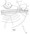
- the Figures 3 and 4 show a perspective view into the interior of the vessel 100. It can be seen that the insert floors 13 extends from the outlet 14 to an end portion 103 of the container 10 obliquely upward. Furthermore, it can be seen that in the upper area of the boiler 100, an inlet 18 is provided for filling the bulk material. Furthermore, the arcuate course of the insert floors 13 is shown in the transverse direction. As a result, the use of floors 13 according to not only a longitudinal gradient, but also a transverse slope. The bulk material introduced through the inlet 18 is thus forced by gravity not only from the end portions 103 in the direction of the outlet 14, but also from the side regions towards the center of the boiler when the outlet 14 is open.
- FIG. 5 shows a perspective view along a feed tray 13 in the direction of the first end portion 133.
- the insert bottoms 13 consists of a metal-made, arcuate plate on the surface of a plurality of longitudinally extending, mutually parallel compressed air hoses 19 is provided.
- the compressed air hoses 19 are fastened with fixing means 191 provided at regular intervals on the insert bottoms 13.
- fixing means 191 provided at regular intervals on the insert bottoms 13.
- FIG. 6 shows a detailed view of the second end portion 134 of an insert base 13.
- the end portion 134 includes a solid end piece 1341, consisting of two planar edge regions 1342 and an intermediate, intermediate region 1343, the arcuate and in the direction of the compressed air hoses 19 tapered downwardly formed is.
- a plurality of connecting pieces 1344 for compressed air hoses 19 connect.
- a compressed air hose 19 is connected in each case.
- a compressed air generating system (not shown here) can introduce compressed air into the individual compressed air hoses 19 via a connection on the end piece 1341 (not shown here).
- FIG. 7 shows a cross section through the use of floors 13, in the Figures 5 and 6 is shown. Herein recognizable in the arcuate course of the insert sheets 13 and the pressure hoses 19 arranged side by side and parallel to one another.
Landscapes
- Engineering & Computer Science (AREA)
- Mechanical Engineering (AREA)
- Transportation (AREA)
- Health & Medical Sciences (AREA)
- Public Health (AREA)
- Filling Or Emptying Of Bunkers, Hoppers, And Tanks (AREA)
- Vehicle Waterproofing, Decoration, And Sanitation Devices (AREA)
- Storage Of Harvested Produce (AREA)
- Sewage (AREA)
- Air Transport Of Granular Materials (AREA)
- Catching Or Destruction (AREA)
Priority Applications (1)
| Application Number | Priority Date | Filing Date | Title |
|---|---|---|---|
| PL07022934T PL2045124T3 (pl) | 2007-10-05 | 2007-11-27 | Zbiornik dla pojazdu silosowego |
Applications Claiming Priority (1)
| Application Number | Priority Date | Filing Date | Title |
|---|---|---|---|
| DE202007013969U DE202007013969U1 (de) | 2007-10-05 | 2007-10-05 | Kessel für ein Silofahrzeug |
Publications (2)
| Publication Number | Publication Date |
|---|---|
| EP2045124A1 EP2045124A1 (de) | 2009-04-08 |
| EP2045124B1 true EP2045124B1 (de) | 2011-04-27 |
Family
ID=39134882
Family Applications (1)
| Application Number | Title | Priority Date | Filing Date |
|---|---|---|---|
| EP07022934A Not-in-force EP2045124B1 (de) | 2007-10-05 | 2007-11-27 | Kessel für ein Silofahrzeug |
Country Status (4)
| Country | Link |
|---|---|
| EP (1) | EP2045124B1 (pl) |
| AT (1) | ATE507106T1 (pl) |
| DE (2) | DE202007013969U1 (pl) |
| PL (1) | PL2045124T3 (pl) |
Family Cites Families (7)
| Publication number | Priority date | Publication date | Assignee | Title |
|---|---|---|---|---|
| DE1143446B (de) * | 1952-04-07 | 1963-02-07 | Fuller Co | Behaelter mit pneumatischer Selbstentleerung |
| US3139286A (en) | 1961-11-13 | 1964-06-30 | Ronald D Johnson | Tank truck hopper body formed with arcuate surfaces |
| BE668265A (pl) * | 1964-08-25 | |||
| DE1997197U (de) * | 1968-07-24 | 1968-11-21 | Bruchsaler Kessel Und Appbau B | Tankwagen insbesondere zum transport und verteilen von fluessigmist. |
| DE7205859U (de) * | 1972-02-17 | 1972-07-06 | Krone B Gmbh | Fahrzeug für feinkörniges Schüttgut |
| US5326156A (en) * | 1992-06-19 | 1994-07-05 | Heider Merle J | Trailer construction |
| FR2815948B1 (fr) * | 2000-10-27 | 2003-02-14 | Gen Trailers France | Reservoir pour un vehicule industriel et procede de vidange d'un tel reservoir |
-
2007
- 2007-10-05 DE DE202007013969U patent/DE202007013969U1/de not_active Expired - Lifetime
- 2007-11-27 AT AT07022934T patent/ATE507106T1/de active
- 2007-11-27 PL PL07022934T patent/PL2045124T3/pl unknown
- 2007-11-27 EP EP07022934A patent/EP2045124B1/de not_active Not-in-force
- 2007-11-27 DE DE502007007072T patent/DE502007007072D1/de active Active
Also Published As
| Publication number | Publication date |
|---|---|
| DE202007013969U1 (de) | 2008-02-28 |
| DE502007007072D1 (de) | 2011-06-09 |
| ATE507106T1 (de) | 2011-05-15 |
| EP2045124A1 (de) | 2009-04-08 |
| PL2045124T3 (pl) | 2011-11-30 |
Similar Documents
| Publication | Publication Date | Title |
|---|---|---|
| DE202013102562U1 (de) | Schwallwandelement, Schwallwandanordnung und Transportbehälter | |
| EP1927506A1 (de) | Fahrzeugrahmen mit Querträgern zur Ladungssicherung und Querträger hierfür | |
| DE3049232C2 (de) | Strebe zur Verbindung der beiden größeren Seitenwände eines Kanisters aus Kunststoff | |
| EP1700740B1 (de) | Kippmulde | |
| EP2045124B1 (de) | Kessel für ein Silofahrzeug | |
| DE10323072B4 (de) | Tankbehälter | |
| DE202009012642U1 (de) | Silobehälter für Staub- oder Schüttgut | |
| DE19808123A1 (de) | Kippmulde | |
| DE29909464U1 (de) | Pritschenaufbau für Schüttgutbehälter | |
| DE10240799A1 (de) | Kippmulde | |
| EP0429693B1 (de) | Speicherbehälter | |
| DE202020100010U1 (de) | Plattformcontainer zur Beförderung von zylinderförmigen Ladegütern | |
| DE2913814A1 (de) | Hochbordiger eisenbahnwagen fuer entladung an einer drehkippvorrichtung | |
| AT256638B (de) | Transportfahrzeug für Schüttgüter aller Art | |
| DE3801700A1 (de) | Doppelwandige bodenplatte eines beluefteten containers | |
| DE202008010166U1 (de) | Runge | |
| EP4464554A1 (de) | Fahrzeug mit konischem laderaum | |
| EP1368219B1 (de) | Schienengebundener güterwagen | |
| DE102006062197B3 (de) | Silofahrzeug | |
| DE202008016364U1 (de) | Silofahrzeug | |
| EP4086194A1 (de) | Auslaufvorrichtung zum entleeren eines silobehälters, silobehälter, fahrzeug mit silobehälter sowie verfahren zur herstellung einer auslaufvorrichtung | |
| DE102009054623A1 (de) | Lkw-Rohrtraverse mit geteiltem Rohr | |
| DE7435968U (de) | Container für körniges und staubförmiges gut | |
| DE7613526U (de) | Transportbehälter | |
| EP1841671A1 (de) | Transportbeh[ltervorrichtung |
Legal Events
| Date | Code | Title | Description |
|---|---|---|---|
| PUAI | Public reference made under article 153(3) epc to a published international application that has entered the european phase |
Free format text: ORIGINAL CODE: 0009012 |
|
| AK | Designated contracting states |
Kind code of ref document: A1 Designated state(s): AT BE BG CH CY CZ DE DK EE ES FI FR GB GR HU IE IS IT LI LT LU LV MC MT NL PL PT RO SE SI SK TR |
|
| AX | Request for extension of the european patent |
Extension state: AL BA HR MK RS |
|
| 17P | Request for examination filed |
Effective date: 20090610 |
|
| 17Q | First examination report despatched |
Effective date: 20090727 |
|
| AKX | Designation fees paid |
Designated state(s): AT BE BG CH CY CZ DE DK EE ES FI FR GB GR HU IE IS IT LI LT LU LV MC MT NL PL PT RO SE SI SK TR |
|
| GRAP | Despatch of communication of intention to grant a patent |
Free format text: ORIGINAL CODE: EPIDOSNIGR1 |
|
| GRAS | Grant fee paid |
Free format text: ORIGINAL CODE: EPIDOSNIGR3 |
|
| GRAA | (expected) grant |
Free format text: ORIGINAL CODE: 0009210 |
|
| AK | Designated contracting states |
Kind code of ref document: B1 Designated state(s): AT BE BG CH CY CZ DE DK EE ES FI FR GB GR HU IE IS IT LI LT LU LV MC MT NL PL PT RO SE SI SK TR |
|
| REG | Reference to a national code |
Ref country code: GB Ref legal event code: FG4D Free format text: NOT ENGLISH |
|
| REG | Reference to a national code |
Ref country code: CH Ref legal event code: EP |
|
| REG | Reference to a national code |
Ref country code: IE Ref legal event code: FG4D Free format text: LANGUAGE OF EP DOCUMENT: GERMAN |
|
| REF | Corresponds to: |
Ref document number: 502007007072 Country of ref document: DE Date of ref document: 20110609 Kind code of ref document: P |
|
| REG | Reference to a national code |
Ref country code: DE Ref legal event code: R096 Ref document number: 502007007072 Country of ref document: DE Effective date: 20110609 |
|
| REG | Reference to a national code |
Ref country code: NL Ref legal event code: VDEP Effective date: 20110427 |
|
| LTIE | Lt: invalidation of european patent or patent extension |
Effective date: 20110427 |
|
| PG25 | Lapsed in a contracting state [announced via postgrant information from national office to epo] |
Ref country code: PT Free format text: LAPSE BECAUSE OF FAILURE TO SUBMIT A TRANSLATION OF THE DESCRIPTION OR TO PAY THE FEE WITHIN THE PRESCRIBED TIME-LIMIT Effective date: 20110829 Ref country code: LT Free format text: LAPSE BECAUSE OF FAILURE TO SUBMIT A TRANSLATION OF THE DESCRIPTION OR TO PAY THE FEE WITHIN THE PRESCRIBED TIME-LIMIT Effective date: 20110427 Ref country code: SE Free format text: LAPSE BECAUSE OF FAILURE TO SUBMIT A TRANSLATION OF THE DESCRIPTION OR TO PAY THE FEE WITHIN THE PRESCRIBED TIME-LIMIT Effective date: 20110427 |
|
| REG | Reference to a national code |
Ref country code: IE Ref legal event code: FD4D |
|
| PG25 | Lapsed in a contracting state [announced via postgrant information from national office to epo] |
Ref country code: IS Free format text: LAPSE BECAUSE OF FAILURE TO SUBMIT A TRANSLATION OF THE DESCRIPTION OR TO PAY THE FEE WITHIN THE PRESCRIBED TIME-LIMIT Effective date: 20110827 Ref country code: GR Free format text: LAPSE BECAUSE OF FAILURE TO SUBMIT A TRANSLATION OF THE DESCRIPTION OR TO PAY THE FEE WITHIN THE PRESCRIBED TIME-LIMIT Effective date: 20110728 Ref country code: SI Free format text: LAPSE BECAUSE OF FAILURE TO SUBMIT A TRANSLATION OF THE DESCRIPTION OR TO PAY THE FEE WITHIN THE PRESCRIBED TIME-LIMIT Effective date: 20110427 Ref country code: CY Free format text: LAPSE BECAUSE OF FAILURE TO SUBMIT A TRANSLATION OF THE DESCRIPTION OR TO PAY THE FEE WITHIN THE PRESCRIBED TIME-LIMIT Effective date: 20110427 Ref country code: LV Free format text: LAPSE BECAUSE OF FAILURE TO SUBMIT A TRANSLATION OF THE DESCRIPTION OR TO PAY THE FEE WITHIN THE PRESCRIBED TIME-LIMIT Effective date: 20110427 Ref country code: ES Free format text: LAPSE BECAUSE OF FAILURE TO SUBMIT A TRANSLATION OF THE DESCRIPTION OR TO PAY THE FEE WITHIN THE PRESCRIBED TIME-LIMIT Effective date: 20110807 Ref country code: FI Free format text: LAPSE BECAUSE OF FAILURE TO SUBMIT A TRANSLATION OF THE DESCRIPTION OR TO PAY THE FEE WITHIN THE PRESCRIBED TIME-LIMIT Effective date: 20110427 |
|
| REG | Reference to a national code |
Ref country code: PL Ref legal event code: T3 |
|
| PG25 | Lapsed in a contracting state [announced via postgrant information from national office to epo] |
Ref country code: NL Free format text: LAPSE BECAUSE OF FAILURE TO SUBMIT A TRANSLATION OF THE DESCRIPTION OR TO PAY THE FEE WITHIN THE PRESCRIBED TIME-LIMIT Effective date: 20110427 |
|
| PG25 | Lapsed in a contracting state [announced via postgrant information from national office to epo] |
Ref country code: EE Free format text: LAPSE BECAUSE OF FAILURE TO SUBMIT A TRANSLATION OF THE DESCRIPTION OR TO PAY THE FEE WITHIN THE PRESCRIBED TIME-LIMIT Effective date: 20110427 Ref country code: IE Free format text: LAPSE BECAUSE OF FAILURE TO SUBMIT A TRANSLATION OF THE DESCRIPTION OR TO PAY THE FEE WITHIN THE PRESCRIBED TIME-LIMIT Effective date: 20110427 |
|
| PG25 | Lapsed in a contracting state [announced via postgrant information from national office to epo] |
Ref country code: DK Free format text: LAPSE BECAUSE OF FAILURE TO SUBMIT A TRANSLATION OF THE DESCRIPTION OR TO PAY THE FEE WITHIN THE PRESCRIBED TIME-LIMIT Effective date: 20110427 Ref country code: RO Free format text: LAPSE BECAUSE OF FAILURE TO SUBMIT A TRANSLATION OF THE DESCRIPTION OR TO PAY THE FEE WITHIN THE PRESCRIBED TIME-LIMIT Effective date: 20110427 Ref country code: SK Free format text: LAPSE BECAUSE OF FAILURE TO SUBMIT A TRANSLATION OF THE DESCRIPTION OR TO PAY THE FEE WITHIN THE PRESCRIBED TIME-LIMIT Effective date: 20110427 |
|
| PLBE | No opposition filed within time limit |
Free format text: ORIGINAL CODE: 0009261 |
|
| STAA | Information on the status of an ep patent application or granted ep patent |
Free format text: STATUS: NO OPPOSITION FILED WITHIN TIME LIMIT |
|
| 26N | No opposition filed |
Effective date: 20120130 |
|
| REG | Reference to a national code |
Ref country code: DE Ref legal event code: R097 Ref document number: 502007007072 Country of ref document: DE Effective date: 20120130 |
|
| BERE | Be: lapsed |
Owner name: FELDBINDER SPEZIALFAHRZEUGWERKE G.M.B.H. Effective date: 20111130 |
|
| PG25 | Lapsed in a contracting state [announced via postgrant information from national office to epo] |
Ref country code: IT Free format text: LAPSE BECAUSE OF FAILURE TO SUBMIT A TRANSLATION OF THE DESCRIPTION OR TO PAY THE FEE WITHIN THE PRESCRIBED TIME-LIMIT Effective date: 20110427 |
|
| PG25 | Lapsed in a contracting state [announced via postgrant information from national office to epo] |
Ref country code: MC Free format text: LAPSE BECAUSE OF NON-PAYMENT OF DUE FEES Effective date: 20111130 |
|
| REG | Reference to a national code |
Ref country code: CH Ref legal event code: PL |
|
| PG25 | Lapsed in a contracting state [announced via postgrant information from national office to epo] |
Ref country code: CH Free format text: LAPSE BECAUSE OF NON-PAYMENT OF DUE FEES Effective date: 20111130 Ref country code: LI Free format text: LAPSE BECAUSE OF NON-PAYMENT OF DUE FEES Effective date: 20111130 |
|
| PG25 | Lapsed in a contracting state [announced via postgrant information from national office to epo] |
Ref country code: BE Free format text: LAPSE BECAUSE OF NON-PAYMENT OF DUE FEES Effective date: 20111130 |
|
| PGFP | Annual fee paid to national office [announced via postgrant information from national office to epo] |
Ref country code: CZ Payment date: 20121116 Year of fee payment: 6 |
|
| PG25 | Lapsed in a contracting state [announced via postgrant information from national office to epo] |
Ref country code: MT Free format text: LAPSE BECAUSE OF FAILURE TO SUBMIT A TRANSLATION OF THE DESCRIPTION OR TO PAY THE FEE WITHIN THE PRESCRIBED TIME-LIMIT Effective date: 20110427 |
|
| PGFP | Annual fee paid to national office [announced via postgrant information from national office to epo] |
Ref country code: PL Payment date: 20121119 Year of fee payment: 6 |
|
| PG25 | Lapsed in a contracting state [announced via postgrant information from national office to epo] |
Ref country code: LU Free format text: LAPSE BECAUSE OF NON-PAYMENT OF DUE FEES Effective date: 20111127 |
|
| PG25 | Lapsed in a contracting state [announced via postgrant information from national office to epo] |
Ref country code: BG Free format text: LAPSE BECAUSE OF FAILURE TO SUBMIT A TRANSLATION OF THE DESCRIPTION OR TO PAY THE FEE WITHIN THE PRESCRIBED TIME-LIMIT Effective date: 20110727 |
|
| PG25 | Lapsed in a contracting state [announced via postgrant information from national office to epo] |
Ref country code: TR Free format text: LAPSE BECAUSE OF FAILURE TO SUBMIT A TRANSLATION OF THE DESCRIPTION OR TO PAY THE FEE WITHIN THE PRESCRIBED TIME-LIMIT Effective date: 20110427 |
|
| PG25 | Lapsed in a contracting state [announced via postgrant information from national office to epo] |
Ref country code: HU Free format text: LAPSE BECAUSE OF FAILURE TO SUBMIT A TRANSLATION OF THE DESCRIPTION OR TO PAY THE FEE WITHIN THE PRESCRIBED TIME-LIMIT Effective date: 20110427 |
|
| REG | Reference to a national code |
Ref country code: AT Ref legal event code: MM01 Ref document number: 507106 Country of ref document: AT Kind code of ref document: T Effective date: 20121130 |
|
| PG25 | Lapsed in a contracting state [announced via postgrant information from national office to epo] |
Ref country code: AT Free format text: LAPSE BECAUSE OF NON-PAYMENT OF DUE FEES Effective date: 20121130 |
|
| PG25 | Lapsed in a contracting state [announced via postgrant information from national office to epo] |
Ref country code: CZ Free format text: LAPSE BECAUSE OF NON-PAYMENT OF DUE FEES Effective date: 20131127 |
|
| PG25 | Lapsed in a contracting state [announced via postgrant information from national office to epo] |
Ref country code: PL Free format text: LAPSE BECAUSE OF NON-PAYMENT OF DUE FEES Effective date: 20131127 |
|
| REG | Reference to a national code |
Ref country code: FR Ref legal event code: PLFP Year of fee payment: 9 |
|
| PGFP | Annual fee paid to national office [announced via postgrant information from national office to epo] |
Ref country code: GB Payment date: 20151123 Year of fee payment: 9 Ref country code: DE Payment date: 20151127 Year of fee payment: 9 |
|
| PGFP | Annual fee paid to national office [announced via postgrant information from national office to epo] |
Ref country code: FR Payment date: 20151124 Year of fee payment: 9 |
|
| REG | Reference to a national code |
Ref country code: DE Ref legal event code: R119 Ref document number: 502007007072 Country of ref document: DE |
|
| GBPC | Gb: european patent ceased through non-payment of renewal fee |
Effective date: 20161127 |
|
| REG | Reference to a national code |
Ref country code: FR Ref legal event code: ST Effective date: 20170731 |
|
| PG25 | Lapsed in a contracting state [announced via postgrant information from national office to epo] |
Ref country code: FR Free format text: LAPSE BECAUSE OF NON-PAYMENT OF DUE FEES Effective date: 20161130 |
|
| PG25 | Lapsed in a contracting state [announced via postgrant information from national office to epo] |
Ref country code: GB Free format text: LAPSE BECAUSE OF NON-PAYMENT OF DUE FEES Effective date: 20161127 Ref country code: DE Free format text: LAPSE BECAUSE OF NON-PAYMENT OF DUE FEES Effective date: 20170601 |