EP2045043B1 - Wheel hub removal device - Google Patents
Wheel hub removal device Download PDFInfo
- Publication number
- EP2045043B1 EP2045043B1 EP08012809A EP08012809A EP2045043B1 EP 2045043 B1 EP2045043 B1 EP 2045043B1 EP 08012809 A EP08012809 A EP 08012809A EP 08012809 A EP08012809 A EP 08012809A EP 2045043 B1 EP2045043 B1 EP 2045043B1
- Authority
- EP
- European Patent Office
- Prior art keywords
- flange
- ring
- bolts
- hub
- wheel hub
- Prior art date
- Legal status (The legal status is an assumption and is not a legal conclusion. Google has not performed a legal analysis and makes no representation as to the accuracy of the status listed.)
- Not-in-force
Links
Images


Classifications
-
- B—PERFORMING OPERATIONS; TRANSPORTING
- B25—HAND TOOLS; PORTABLE POWER-DRIVEN TOOLS; MANIPULATORS
- B25B—TOOLS OR BENCH DEVICES NOT OTHERWISE PROVIDED FOR, FOR FASTENING, CONNECTING, DISENGAGING OR HOLDING
- B25B27/00—Hand tools, specially adapted for fitting together or separating parts or objects whether or not involving some deformation, not otherwise provided for
- B25B27/02—Hand tools, specially adapted for fitting together or separating parts or objects whether or not involving some deformation, not otherwise provided for for connecting objects by press fit or detaching same
- B25B27/026—Hand tools, specially adapted for fitting together or separating parts or objects whether or not involving some deformation, not otherwise provided for for connecting objects by press fit or detaching same fluid driven
Definitions
- the invention relates to a wheel hub removal device for removing a wheel hub from a bearing located in a steering knuckle according to the features in the preamble of claim 1.
- a Radnabendemontagevortechnisch of the generic type is from the DE 20 2004 010 887 U1 known.
- two or three stud bolts are screwed into threaded holes in the hub flange.
- a flange plate is determined.
- the flange plate serves to hold a press unit.
- a pressure plate is provided, which is supported by pressure bolts on a support ring which is incorporated between the stub axle and the wheel hub.
- the pressure pins are inserted through the threaded holes, which are not occupied by the studs.
- a Wheel hub with a five-hole flange and a use of three studs can therefore be used two pressure pin.
- the known device has proven very well in practice. However, there are vehicles or vehicle types in which the extraction of the wheel hub with mounted joint or drive shaft due to the space-constrained conditions is difficult, because you can not get to the threaded holes in the Radflanschnabe to set the studs hereon. Also for dismantling sometimes so high extraction forces are required that the known disassembly device, because there can be used only two or three pressure pin, reaches its limits.
- the invention is based on the prior art based on the object to improve a Radnabeterontagevorraum application technology, especially in terms of power transmission, and designed so that even such hubs can be removed in which a determination of the stud directly on the hub flange is not possible.
- a flange adapter which is fixable on the wheel hub flange and projects circumferentially relative to the wheel hub flange, wherein in the flange adapter receptacles are provided for the stud bolts, via which the stud bolts are coupled to the flange adapter.
- the flange adapter according to the invention creates opposite the wheel hub flange further outward recordings or connection options for fixing the studs. These can now be fixed to the flange adapter, which is connected to the hub flange. The rear flange plate is fixed to the stud bolt. Subsequently, the remaining device components are mounted.
- a further advantage is that it no longer has to resort directly to the threaded bores in the wheel hub flange for fixing the stud bolts.
- the stud bolts are mounted and fixed at the free end of the flange plate.
- the pressure plate is positioned, which is supported on the support ring via the pressure bolts, which are inserted through the threaded holes in the hub flange.
- the press unit is incorporated. Upon actuation of the pressing unit, the axial force generated thereby is transmitted via the pressure pin and the support plate on the steering knuckle and pulled out of the wheel hub from the bearing in the steering knuckle.
- the flange adapter is annular and composed of two mutually coupled ring segments. This allows a simple and secure installation of the flange adapter even in confined spaces.
- the flange adapter In the flange adapter an annular groove is formed.
- the flange adapter engages around the outer circumference of the wheel hub flange with the annular groove.
- the groove base rests against the outer surface of the wheel hub flange and the two side legs of the annular groove or the flange adapter engage around the wheel hub flange.
- the ring segments of the flange adapter are connected by bolts extending in their plane.
- the stability of the connection between the ring segments can be further increased if positive-locking elements are provided on the contacting abutment surfaces of the ring segments, which engage with each other. In this way, also a fit connection can be made.
- the interlocking elements are formed by pins and pin holes.
- a press unit which comprises a hydraulic cylinder and a threaded spindle.
- the threaded spindle passes through with its base body a hole in the flange plate and is fixed to this.
- the support ring which is installed between the stub axle and the wheel hub, is preferably also formed by two mutually coupled ring segments, which are connectable by means of bolts.
- interlocking interlocking elements are provided on the contacting abutment surfaces of the ring segments. These also consist of pins and mortises, the bolts pass through the pins.
- annular surfaces are provided in the support ring two remote via a step.
- the annular surfaces have different diameters and are configured so that the support ring engages around the front end of the wheel hub. This is the inner ring surface on the front side of the steering knuckle. In this way, a stable fixing and support of the support ring is ensured on the steering knuckle.
- the wheel hub 2 has a wheel hub flange 4 with threaded holes 5 and is seated with its hub neck 6 in a roller bearing 7, which is mounted in a bearing bore 8 of the steering knuckle 3.
- the Radnabendemontagevorides 1 comprises a flange 9, which is indirectly supported via studs 10 on the hub flange 4 with the inclusion of a flange adapter 11.
- the flange adapter 11 can be fixed to the wheel hub flange 4.
- the flange adapter 11 is annular and can be assembled from two ring segments 12, 13 which can be coupled together.
- the ring segments 12, 13 are connected by extending in its plane E bolt 14 together. These are guided by lateral holes 15 in the ring segment 12.
- At the contacting abutment surfaces 16, 17 of the ring segments 12, 13 form-fitting elements 18 in the form of pins 19 on the ring segment 12 and pin holes 20 are formed on the ring segment 13 which engage with each other. As a result, a fitting connection between the ring segments 12, 13 is produced.
- the pins 19 are designed sleeve-shaped, so that the bolts 14 can be screwed through the holes 15 through the pins 19 and the pin holes 20 into threaded holes 21 in the ring segment 13 and the ring segments 12, 13 can be clamped together.
- the flange adapter 11 has a circumferential annular groove 22 and engages around the outer circumference 23 of the wheel hub flange 4 with the annular groove 22.
- the groove base 24 bears against the outer surface 25 of the wheel hub flange 4.
- the two side legs 26, 27 of the flange adapter 11 surround the wheel hub flange 4 and are laterally on this. In this way, a stable coupling of the flange adapter 11 is ensured with the hub flange 4, via which high tensile and compressive forces can be transmitted.
- flange adapter 11 projects circumferentially relative to the wheel hub flange 4.
- receptacles 28 are provided in the form of threaded holes into which the stud bolts 10 are each screwed with a threaded end 29.
- the flange plate 9 can be fixed.
- through holes 31 are provided in the flange plate 9, through which cylinder screws 32 can be passed and screwed into threaded bores 33 of the stud bolts 10 at the end.
- the wheel hub removal device 1 further includes a pressure plate 34 which is positioned between the stud bolts 10.
- the pressure plate 34 is supported via pressure pin 35 on a support ring 36, which between the stub axle. 3 and the wheel hub 2 is incorporated.
- the pressure pins 35 are inserted through the threaded holes 5 in the hub flange 4 to rest on the support ring 36. At the wheel hub flange 4 facing away from the end 37 of the pressure pin 35, these engage in blind holes 38 of the pressure plate 34 a.
- the stud bolts 10 are provided at their end 30 with a profiled corrugated portion 40.
- the support ring 36 is also composed of two mutually coupled ring segments 41, 42, which are braced by means of bolts 43 with each other.
- ring segments 41, 42 At the contacting abutment surfaces 44, 45 of the ring segments 41, 42 form-fitting elements 46 in the form of pins 47 and pin holes 48 are provided, which engage with each other.
- the bolts 43 pass through the pins 47 and the pin holes 48 and are screwed into threaded holes 49 in the ring segment 42.
- the support ring 36 has two offset over a step 50 annular surfaces 51, 52.
- the support ring 36 thus surrounds the front end 53 of the hub neck 6, wherein the inner annular surface 51 abuts the end face of the steering knuckle 3.
- the annular surface 52 extends at a distance to a shoulder 54 of the hub neck 6.
- the pressing unit 55 comprises a hydraulic cylinder 56 and a threaded spindle 57.
- the threaded spindle 57 has a base body 59 provided with an external thread 58 and is screwed with this into a provided with an internal thread 60 bore 61 in the flange plate 9.
- an actuating polygon 63 is provided at the free end 62 of the threaded spindle 57.
- a spigot 65 is provided at the hydraulic cylinder 56 facing the end 64 of the threaded spindle 57.
- the hydraulic cylinder 56 can be pre-centered during assembly.
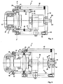
- the Figures 2 and 4 show the Radnabeterontagevorraum 1 in the mounted state before pulling out the wheel hub 2 from the steering knuckle 3.
- the hydraulic cylinder 56 of the pressing unit 55 By Actuation of the hydraulic cylinder 56 of the pressing unit 55 with pressure, the hydraulic cylinder 56 is extended. The force is transmitted to the pressure plate 34, which is supported on the steering knuckle 3 via the pressure bolts 35 and the support ring 36. The introduction of force leads to a displacement of the pressing unit 55 together with the flange plate 9 and the stud bolt 10 away from the steering knuckle 3, so that the wheel hub 2 is pulled out of the roller bearing 7 in the steering knuckle 3. This is in the Figures 3 and 5 clarified.
- the hydraulic cylinder 56 If the available stroke of the hydraulic cylinder 56 is insufficient for pulling out the wheel hub 2, the hydraulic cylinder 56 is depressurized and the threaded spindle 57 is actuated. As a result, the hydraulic cylinder 56 is pressed back into its starting position. Subsequently, the hydraulic cylinder 56 can be pressurized again and the available hub be used again until the hub 2 is completely pulled out of the steering knuckle 3 and can be dismantled.
Abstract
Description
Die Erfindung betrifft eine Radnabendemontagevorrichtung zum Ausziehen einer Radnabe aus einem in einem Achsschenkel befindlichen Lager gemäß den Merkmalen im Oberbegriff von Anspruch 1.The invention relates to a wheel hub removal device for removing a wheel hub from a bearing located in a steering knuckle according to the features in the preamble of
Eine Radnabendemontagevorrichtung der gattungsgemäßen Art ist aus der
Die bekannte Vorrichtung hat sich in der Praxis sehr gut bewährt. Es gibt jedoch Fahrzeuge bzw. Fahrzeugtypen, bei denen das Ausziehen der Radnabe bei montierter Gelenk- bzw. Antriebswelle auf Grund der räumlich beengten Verhältnisse nur schwer möglich ist, weil man an die Gewindebohrungen in der Radflanschnabe nicht herankommt, um hieran die Stehbolzen festzulegen. Auch sind für die Demontage teilweise so hohe Ausziehkräfte erforderlich, dass die bekannte Demontagevorrichtung, weil dort nur zwei bzw. drei Druckbolzen eingesetzt werden können, an ihre Grenzen stößt.The known device has proven very well in practice. However, there are vehicles or vehicle types in which the extraction of the wheel hub with mounted joint or drive shaft due to the space-constrained conditions is difficult, because you can not get to the threaded holes in the Radflanschnabe to set the studs hereon. Also for dismantling sometimes so high extraction forces are required that the known disassembly device, because there can be used only two or three pressure pin, reaches its limits.
Der Erfindung liegt ausgehend vom Stand der Technik die Aufgabe zu Grunde, eine Radnabendemontagevorrichtung anwendungstechnisch, insbesondere hinsichtlich der Kraftübertragung, zu verbessern und so auszulegen, dass auch solche Radnaben ausgebaut werden können, bei denen eine Festlegung der Stehbolzen unmittelbar am Radnabenflansch nicht möglich ist.The invention is based on the prior art based on the object to improve a Radnabeterontagevorrichtung application technology, especially in terms of power transmission, and designed so that even such hubs can be removed in which a determination of the stud directly on the hub flange is not possible.
Die Lösung dieser Aufgabe besteht nach der Erfindung in einer Radnabendemontagevorrichtung gemäß den Merkmalen von Anspruch 1.The solution to this problem consists according to the invention in a Radnabendemontagevorrichtung according to the features of
Danach ist ein Flanschadapter vorgesehen, welcher am Radnabenflansch festlegbar ist und umfangsseitig gegenüber dem Radnabenflansch vorsteht, wobei im Flanschadapter Aufnahmen für die Stehbolzen vorgesehen sind, über welche die Stehbolzen mit dem Flanschadapter koppelbar sind.Thereafter, a flange adapter is provided, which is fixable on the wheel hub flange and projects circumferentially relative to the wheel hub flange, wherein in the flange adapter receptacles are provided for the stud bolts, via which the stud bolts are coupled to the flange adapter.
Der erfindungsgemäße Flanschadapter schafft gegenüber dem Radnabenflansch weiter außen liegende Aufnahmen bzw. Anschlussmöglichkeiten zum Festlegen der Stehbolzen. Diese können nun am Flanschadapter festgelegt werden, welcher mit dem Radnabenflansch verbunden ist. An den Stehbolzen wird die rückwärtige Flanschplatte festgelegt. Anschließend werden die übrigen Vorrichtungsbauteile montiert.The flange adapter according to the invention creates opposite the wheel hub flange further outward recordings or connection options for fixing the studs. These can now be fixed to the flange adapter, which is connected to the hub flange. The rear flange plate is fixed to the stud bolt. Subsequently, the remaining device components are mounted.
Vorteilhaft ist weiterhin, dass für die Festlegung der Stehbolzen nicht mehr direkt auf die Gewindebohrungen im Radnabenflansch zurückgegriffen werden muss.A further advantage is that it no longer has to resort directly to the threaded bores in the wheel hub flange for fixing the stud bolts.
Dementsprechend können mehr Stehbolzen als bisher montiert werden. Die Gewindebohrungen im Radnabenflansch stehen alle für die Druckbolzen zur Verfügung, so dass auch mehr Druckbolzen eingesetzt werden können. Über die Druckbolzen stützt sich die Druckplatte an dem zwischen der Radnabe und dem Achsschenkel angeordneten Stützring ab. Demzufolge können bei der erfindungsgemäßen Radnabendemontagevorrichtung erheblich höhere Kräfte zum Ausziehen der Radnabe übertragen werden.Accordingly, more stud bolts can be mounted than before. The threaded holes in the hub flange are all available for the pressure bolts, so that more pressure bolts can be used. About the pressure pin, the pressure plate is supported on the arranged between the hub and the steering knuckle support ring. Consequently, in the Radnabendemontagevorrichtung invention considerably higher forces to extend the wheel hub can be transmitted.
Vorteilhafte Ausgestaltungen und Weiterbildungen des grundsätzlichen Erfindungsgedankens sind Gegenstand der abhängigen Ansprüche 2 bis 12.Advantageous embodiments and further developments of the basic concept of the invention are the subject of the
Für die Praxis bietet es sich an, die Aufnahmen im Flanschadapter als Gewindebohrungen auszubilden, in welche die Stehbolzen jeweils mit einem Gewindeende eingeschraubt werden können. Diese Ausbildung ist fertigungs- und anwendungstechnisch vorteilhaft.In practice, it makes sense to form the recordings in the flange adapter as threaded holes into which the studs can be screwed in each case with a threaded end. This training is manufacturing and application technology advantageous.
Nachdem der Flanschadapter am Radnabenflansch festgelegt ist, werden die Stehbolzen montiert und an deren freien Ende die Flanschplatte festgelegt. Zwischen die Stehbolzen wird die Druckplatte positioniert, welche sich über die Druckbolzen, die durch die Gewindebohrungen im Radnabenflansch gesteckt werden, am Stützring abstützt. Zwischen Flanschplatte und Druckplatte wird die Presseinheit eingegliedert. Bei Betätigung der Presseinheit wird die hierdurch erzeugte Axialkraft über die Druckbolzen und die Stützplatte auf den Achsschenkel übertragen und die Radnabe aus dem Lager im Achsschenkel herausgezogen.After the flange adapter is fixed to the hub flange, the stud bolts are mounted and fixed at the free end of the flange plate. Between the studs, the pressure plate is positioned, which is supported on the support ring via the pressure bolts, which are inserted through the threaded holes in the hub flange. Between flange plate and pressure plate, the press unit is incorporated. Upon actuation of the pressing unit, the axial force generated thereby is transmitted via the pressure pin and the support plate on the steering knuckle and pulled out of the wheel hub from the bearing in the steering knuckle.
Zweckmäßigerweise ist der Flanschadapter ringförmig ausgebildet und aus zwei miteinander koppelbaren Ringsegmenten zusammengesetzt. Dies ermöglicht eine einfache und handhabungssichere Montage des Flanschadapters auch unter beengten räumlichen Verhältnissen.Appropriately, the flange adapter is annular and composed of two mutually coupled ring segments. This allows a simple and secure installation of the flange adapter even in confined spaces.
Im Flanschadapter ist eine Ringnut ausgebildet. Mit der Ringnut umgreift der Flanschadapter den Außenumfang des Radnabenflanschs. Dabei liegt der Nutgrund an der Außenfläche des Radnabenflanschs an und die beiden Seitenschenkel der Ringnut bzw. des Flanschadapters umgreifen den Radnabenflansch. Hierdurch ist eine besonders stabile Festlegung und Halterung des Flanschadapters am Radnabenflansch möglich, welche die Übertragung hoher Kräfte beim Ausziehen der Radnabe zulässt.In the flange adapter an annular groove is formed. The flange adapter engages around the outer circumference of the wheel hub flange with the annular groove. In this case, the groove base rests against the outer surface of the wheel hub flange and the two side legs of the annular groove or the flange adapter engage around the wheel hub flange. This is a particularly stable fixing and mounting of the flange adapter on Radnabenflansch possible, which allows the transmission of high forces when pulling the wheel hub.
Die Ringsegmente des Flanschadapters sind über sich in ihrer Ebene erstreckende Schraubbolzen verbunden. Die Stabilität der Verbindung zwischen den Ringsegmenten kann weiterhin gesteigert werden, wenn an den einander kontaktierenden Stoßflächen der Ringsegmente Formschlusselemente vorgesehen sind, welche miteinander in Eingriff gelangen. Auf diese Weise kann zudem eine Passverbindung hergestellt werden. Zweckmäßigerweise sind die Formschlusselemente durch Zapfen und Zapfenlöcher gebildet. Beim Koppeln der Ringsegmente werden die Zapfen des einen Ringsegments in die Zapfenlöcher des anderen Ringsegments eingeführt. Weiterhin werden die Schraubbolzen durch die Zapfen hindurchgeführt und in Gewindebohrungen festgelegt, wobei die Gewindebohrungen die Fortsetzung der Zapfenlöcher bilden.The ring segments of the flange adapter are connected by bolts extending in their plane. The stability of the connection between the ring segments can be further increased if positive-locking elements are provided on the contacting abutment surfaces of the ring segments, which engage with each other. In this way, also a fit connection can be made. Conveniently, the interlocking elements are formed by pins and pin holes. When coupling the ring segments, the pins of one ring segment are inserted into the pin holes of the other ring segment. Furthermore, the bolts are passed through the pins and set in threaded holes, the threaded holes form the continuation of the pin holes.
Als Presseinheit können unterschiedliche Krafterzeuger, beispielsweise mechanische oder hydraulische Gewindespindeln, zum Einsatz gelangen. Als für die Praxis besonders vorteilhaft wird eine Presseinheit angesehen, welche einen Hydraulikzylinder und eine Gewindespindel umfasst. Die Gewindespindel durchsetzt mit ihrem Basiskörper eine Bohrung in der Flanschplatte und ist an dieser festgelegt. Durch die Kombination eines Hydraulikzylinders und einer Gewindespindel kann der zur Verfügung stehende Hub- bzw. Ausziehweg der Presseinheit vergrößert werden.As a pressing unit, different force generators, for example mechanical or hydraulic threaded spindles, can be used. As is particularly advantageous for practice, a press unit is considered, which comprises a hydraulic cylinder and a threaded spindle. The threaded spindle passes through with its base body a hole in the flange plate and is fixed to this. By combining a hydraulic cylinder and a threaded spindle, the available stroke or Ausziehweg the press unit can be increased.
Der Stützring, welcher zwischen dem Achsschenkel und der Radnabe eingebaut wird, ist vorzugsweise ebenfalls durch zwei miteinander koppelbare Ringsegmente gebildet, welche mittels Schraubbolzen verbindbar sind. Auch hier sind an den einander kontaktierenden Stoßflächen der Ringsegmente miteinander in Eingriff gelangende Formschlusselemente vorgesehen. Diese bestehen ebenfalls aus Zapfen und Zapfenlöchern, wobei die Schraubbolzen die Zapfen durchsetzen.The support ring, which is installed between the stub axle and the wheel hub, is preferably also formed by two mutually coupled ring segments, which are connectable by means of bolts. Here, too, interlocking interlocking elements are provided on the contacting abutment surfaces of the ring segments. These also consist of pins and mortises, the bolts pass through the pins.
Im Stützring sind zwei über eine Stufe abgesetzte Ringflächen vorgesehen. Die Ringflächen besitzen verschiedene Durchmesser und sind so konfiguriert, dass der Stützring das vordere Ende der Radnabe umgreift. Hierbei liegt die innere Ringfläche stirnseitig am Achsschenkel an. Auf diese Weise ist eine stabile Festlegung und Abstützung des Stützrings am Achsschenkel gewährleistet.In the support ring two remote via a step annular surfaces are provided. The annular surfaces have different diameters and are configured so that the support ring engages around the front end of the wheel hub. This is the inner ring surface on the front side of the steering knuckle. In this way, a stable fixing and support of the support ring is ensured on the steering knuckle.
Die Erfindung ist nachfolgend anhand eines in den Zeichnungen dargestellten Ausführungsbeispiels näher beschrieben. Es zeigen:
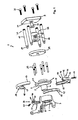
Figur 1- eine erfindungsgemäße Radnabendemontagevorrichtung in einer Expositionsdarstellung ihrer Bauteile nebst Achsschenkel und Radnabe;
Figur 2- in perspektivischer Darstellungsweise die Radnabendemontagevorrichtung im an einer Radnabe montierten Zustand vor dem Ausziehen der Radnabe, wobei das in der Bildebene vordere Ringsegment des Stützrings nicht dargestellt ist;
Figur 3- eine perspektivische Darstellung analog zu der von
Figur 2 Figur 4- in der Seitenansicht, teilweise in geschnittener Darstellungsweise, die erfindungsgemäße Vorrichtung vor dem Ausziehen der Radnabe und
Figur 5- in der Seitenansicht, teilweise in geschnittener Darstellungsweise, die erfindungsgemäße Vorrichtung nach dem Ausziehen der Radnabe.
- FIG. 1
- a Radnabendemontagevorrichtung invention in an exposure representation of its components together with the knuckle and wheel hub;
- FIG. 2
- in perspective representation, the Radnabeterontagevorrichtung in mounted on a hub state before pulling out the wheel hub, wherein the front in the image plane ring segment of the support ring is not shown;
- FIG. 3
- a perspective view analogous to that of
FIG. 2 , but with extended wheel hub; - FIG. 4
- in the side view, partially in a sectional representation, the device according to the invention before pulling out the wheel hub and
- FIG. 5
- in the side view, partially in a sectional representation, the device according to the invention after the removal of the wheel hub.
Anhand der
Die Radnabendemontagevorrichtung 1 umfasst eine Flanschplatte 9, welche über Stehbolzen 10 am Radnabenflansch 4 unter Eingliederung eines Flanschadapters 11 mittelbar abstützbar ist. Hierzu ist der Flanschadapter 11 am Radnabenflansch 4 festlegbar.The
Man erkennt, dass der Flanschadapter 11 ringförmig ausgebildet ist und aus zwei miteinander koppelbaren Ringsegmenten 12, 13 zusammensetzbar ist. Hierzu sind die Ringsegmente 12, 13 durch sich in ihrer Ebene E erstreckende Schraubbolzen 14 miteinander verbunden. Diese werden durch seitliche Bohrungen 15 im Ringsegment 12 geführt. An den einander kontaktierenden Stoßflächen 16, 17 der Ringsegmente 12, 13 sind Formschlusselemente 18 in Form von Zapfen 19 am Ringsegment 12 und Zapfenlöchern 20 am Ringsegment 13 ausgebildet, welche miteinander in Eingriff gelangen. Hierdurch wird eine Passverbindung zwischen den Ringsegmenten 12, 13 hergestellt. Die Zapfen 19 sind hülsenförmig gestaltet, so dass die Schraubbolzen 14 über die Bohrungen 15 durch die Zapfen 19 und die Zapfenlöcher 20 bis in Gewindebohrungen 21 im Ringsegment 13 eingeschraubt und die Ringsegmente 12, 13 miteinander verspannt werden können.It can be seen that the
Man erkennt des Weiteren, dass der Flanschadapter 11 eine umlaufende Ringnut 22 aufweist und mit der Ringnut 22 den Außenumfang 23 des Radnabenflanschs 4 umgreift. Hierbei liegt der Nutgrund 24 an der Außenfläche 25 des Radnabenflanschs 4 an. Die beiden Seitenschenkel 26, 27 des Flanschadapters 11 umgreifen den Radnabenflansch 4 bzw. liegen seitlich an diesem an. Auf diese Weise ist eine stabile Kopplung des Flanschadapters 11 mit dem Radnabenflansch 4 sichergestellt, über welche hohe Zug- und Druckkräfte übertragen werden können.It can further be seen that the
Der Flanschadapter 11 steht umfangsseitig gegenüber dem Radnabenflansch 4 vor. Im Flanschadapter 11 sind Aufnahmen 28 in Form von Gewindebohrungen vorgesehen, in welche die Stehbolzen 10 jeweils mit einem Gewindeende 29 eingeschraubt werden.The
Am vom Radnabenflansch 4 abgewandten Ende 30 der Stehbolzen 10 ist die Flanschplatte 9 festlegbar. In der Flanschplatte 9 sind hierzu Durchgangsbohrungen 31 vorgesehen, durch welche Zylinderschrauben 32 hindurchgeführt und in stirnseitige Gewindebohrungen 33 der Stehbolzen 10 eingeschraubt werden können.At the end remote from the
Die Radnabendemontagevorrichtung 1 umfasst ferner eine Druckplatte 34, welche zwischen den Stehbolzen 10 positioniert wird. Die Druckplatte 34 stützt sich über Druckbolzen 35 an einem Stützring 36 ab, welcher zwischen dem Achsschenkel 3 und der Radnabe 2 eingegliedert ist. Die Druckbolzen 35 werden durch die Gewindebohrungen 5 im Radnabenflansch 4 bis zur Anlage am Stützring 36 gesteckt. An dem dem Radnabenflansch 4 abgewandten Ende 37 der Druckbolzen 35 greifen diese in Sackbohrungen 38 der Druckplatte 34 ein.The wheel
Zur Erleichterung der Handhabung der Druckbolzen 35 weisen diese einen mit einer Profilierung versehenen Riffelabschnitt 39 auf. Auch die Stehbolzen 10 sind an ihrem Ende 30 mit einem profilierten Riffelabschnitt 40 versehen.To facilitate the handling of the
Der Stützring 36 ist ebenfalls aus zwei miteinander koppelbaren Ringsegmenten 41, 42 zusammengesetzt, welche mittels Schraubbolzen 43 miteinander verspannt werden. An den einander kontaktierenden Stoßflächen 44, 45 der Ringsegmente 41, 42 sind Formschlusselemente 46 in Form von Zapfen 47 und Zapfenlöchern 48 vorgesehen, welche miteinander in Eingriff gelangen. Die Schraubbolzen 43 durchsetzen die Zapfen 47 sowie die Zapfenlöcher 48 und werden in Gewindebohrungen 49 im Ringsegment 42 eingeschraubt.The
Der Stützring 36 weist zwei über eine Stufe 50 abgesetzte Ringflächen 51, 52 auf. Der Stützring 36 umgreift so das vordere Ende 53 des Nabenstutzens 6, wobei die innere Ringfläche 51 stirnseitig am Achsschenkel 3 anliegt. Die Ringfläche 52 verläuft im Abstand zu einem Absatz 54 des Nabenstutzens 6.The
Zwischen der Flanschplatte 9 und der Druckplatte 34 wird eine Presseinheit 55 eingegliedert. Die Presseinheit 55 umfasst einen Hydraulikzylinder 56 und eine Gewindespindel 57. Die Gewindespindel 57 besitzt einen mit einem Außengewinde 58 versehenen Basiskörper 59 und ist mit diesem in eine mit einem Innengewinde 60 versehene Bohrung 61 in der Flanschplatte 9 eingeschraubt. Am freien Ende 62 der Gewindespindel 57 ist ein Betätigungsmehrkant 63 vorgesehen. An dem dem Hydraulikzylinder 56 zugewandten Ende 64 der Gewindespindel 57 ist ein Zentrieransatz 65 vorgesehen. Über den Zentrieransatz 65 kann der Hydraulikzylinder 56 bei der Montage vorzentriert werden.Between the
Die
Reicht der zur Verfügung stehende Hub des Hydraulikzylinders 56 nicht zum Ausziehen der Radnabe 2 aus, wird der Hydraulikzylinder 56 drucklos geschaltet und die Gewindespindel 57 betätigt. Hierdurch wird der Hydraulikzylinder 56 wieder in seine Ausgangsstellung gedrückt. Anschließend kann der Hydraulikzylinder 56 erneut mit Druck beaufschlagt werden und der zur Verfügung stehende Hub nochmals ausgenutzt werden bis die Radnabe 2 vollständig aus dem Achsschenkel 3 herausgezogen ist und demontiert werden kann.If the available stroke of the
- 1 -1 -
- RadnabendemontagevorrichtungHub dismantling device
- 2 -2 -
- Radnabewheel hub
- 3 -3 -
- Achsschenkeljournal
- 4 -4 -
- Radnabenflanschwheel hub
- 5 -5 -
- Gewindebohrungthreaded hole
- 6 -6 -
- Nabenstutzenhub socket
- 7 -7 -
- Wälzlagerroller bearing
- 8 -8th -
- Lagerbohrungbearing bore
- 9 -9 -
- Flanschplatteflange
- 10 -10 -
- Stehbolzenstuds
- 11 -11 -
- Flanschadapterflange
- 12 -12 -
- Ringsegment v. 11Ring segment v. 11
- 13 -13 -
- Ringsegment v. 11Ring segment v. 11
- 14 -14 -
- Schraubbolzenbolts
- 15 -15 -
- Bohrungdrilling
- 16 -16 -
- Stoßfläche v. 12Impact area v. 12
- 17 -17 -
- Stoßfläche v. 13Impact area v. 13
- 18 -18 -
- FormschlusselementForm-fitting element
- 19 -19 -
- Zapfenspigot
- 20 -20 -
- Zapfenlochmortise
- 21 -21 -
- Gewindebohrungthreaded hole
- 22 -22 -
- Ringnutring groove
- 23 -23 -
- Außenumfangouter periphery
- 24 -24 -
- Nutgrundgroove base
- 25 -25 -
- Außenflächeouter surface
- 26 -26 -
- Seitenschenkelside leg
- 27 -27 -
- Seitenschenkelside leg
- 28 -28 -
- Aufnahmeadmission
- 29 -29 -
- Gewindeendethreaded end
- 30 -30 -
- Ende v. 10End of v. 10
- 31 -31 -
- DurchgangsbohrungThrough Hole
- 32 -32 -
- Zylinderschraubecylinder head screw
- 33 -33 -
- Gewindebohrungthreaded hole
- 34 -34 -
- Druckplatteprinting plate
- 35 -35 -
- Druckbolzenpushpin
- 36 -36 -
- Stützringsupport ring
- 37 -37 -
- Ende v. 35End of v. 35
- 38 -38 -
- Sackbohrungblind hole
- 39 -39 -
- RiffelabschnittRiffel section
- 40 -40 -
- RiffelabschnittRiffel section
- 41 -41 -
- Ringsegment v. 36Ring segment v. 36
- 42 -42 -
- Ringsegment v. 36Ring segment v. 36
- 43 -43 -
- Schraubbolzenbolts
- 44 -44 -
- Stoßfläche v. 41Impact area v. 41
- 45 -45 -
- Stoßfläche v. 42Impact area v. 42
- 46 -46 -
- FormschlusselementForm-fitting element
- 47 -47 -
- Zapfenspigot
- 48 -48 -
- Zapfenlochmortise
- 49 -49 -
- Gewindebohrungthreaded hole
- 50 -50 -
- Stufestep
- 51 -51 -
- Ringflächering surface
- 52 -52 -
- Ringflächering surface
- 53 -53 -
- Ende v. 6End of v. 6
- 54 -54 -
- Absatzparagraph
- 55 -55 -
- Presseinheitpress unit
- 56 -56 -
- Hydraulikzylinderhydraulic cylinders
- 57 -57 -
- Gewindespindelscrew
- 58 -58 -
- Außengewindeexternal thread
- 59 -59 -
- Basiskörper v. 57Basic body v. 57
- 60 -60 -
- Innengewindeinner thread
- 61 -61 -
- Bohrungdrilling
- 62 -62 -
- Ende v. 57End of v. 57
- 63 -63 -
- BetätigungsmehrkantOperation polygonal
- 64 -64 -
- Ende v. 57End of v. 57
- 65 -65 -
- ZentrieransatzSpigot
- E -E -
- Ebenelevel
Claims (12)
- Device for dismantling a hub (2) from a bearing (7) in an axle journal (3), which encompasses a flange plate (9), which is supported by studs (10) on the hub flange (4) and a provided pressure plate (34), which uses thrust bolts (35) on a thrust ring (36) to support itself, whereby the thrust ring (36) is arranged between the axle journal (3) and the hub (2) and the thrust bolts (35) are threaded through threads (5) in the hub flange (4) and a press unit (55) can be inserted between the flange plate (9) and the pressure plate (34), characterised by a flange adapter (11), which can be fixed at the hub flange (4) and protrudes over the hub flange(4) and the flange adapter (11) shows receptacles (28) for the thrust bolts (10), which can be coupled to the flange adapter (11).
- Device according to claim 1, characterised by the receptacles (28) through threaded holes in the flange adapter (11), into which the thrust bolts (10) can be screwed with one end of the thread (29).
- Device according to claim 1 or 2, characterised by the flange adapter (11) which is circular shaped and consists of two ring segments (12.13) which can be coupled.
- Device according to at least one of the claims 1 to 3, characterised by the flange adapter (11) showing a ring nut (22) which encompasses the outer circumference (23) of the hub flange (4) with the ring nut (22).
- Device according to claim 3 or 4, characterised by the ring segments (12, 13) being connected by bolts (14) across their plane (E).
- Device according to claim 3 to 5, characterised by the contacting butt joint surfaces (16, 17) of ring segments (12, 13) constituting form fit elements (18).
- Device according to claim 5 and 6, characterised by the form fit elements (18) being formed by studs (19) and stud holes (20), and the bolts (14) penetrating the studs (19).
- Device according to at least one of the claims 1 to 7, characterised by the press unit (55) encompassing a hydraulic cylinder (56) and a threaded spindle (57).
- Device according to claim 8, characterised by the threaded spindle (57) with its base body (59) penetrating a drill hole (61) in the flange plate (9).
- Device according to at least one of the claims 1 to 9, characterised by the support ring (36) which is formed by two ring segments which can be coupled (41, 42), and can be joined by bolts (43), with the contacting butt joint surfaces (16,17) of ring segments (41,42) constituting form fit elements (46).
- Device according to claim 10, characterised by the form fit elements (46) being formed by studs (47) and stud holes (48) and the bolts (43) penetrating the studs (47).
- Device according to at least one of the claims 1 to 11, characterised by two stepped (50) ring surfaces (51, 52) being provided in support ring (36).
Applications Claiming Priority (1)
| Application Number | Priority Date | Filing Date | Title |
|---|---|---|---|
| DE202007013718U DE202007013718U1 (en) | 2007-10-01 | 2007-10-01 | Hub dismantling device |
Publications (3)
| Publication Number | Publication Date |
|---|---|
| EP2045043A2 EP2045043A2 (en) | 2009-04-08 |
| EP2045043A3 EP2045043A3 (en) | 2010-04-14 |
| EP2045043B1 true EP2045043B1 (en) | 2010-12-01 |
Family
ID=38825770
Family Applications (1)
| Application Number | Title | Priority Date | Filing Date |
|---|---|---|---|
| EP08012809A Not-in-force EP2045043B1 (en) | 2007-10-01 | 2008-07-16 | Wheel hub removal device |
Country Status (4)
| Country | Link |
|---|---|
| EP (1) | EP2045043B1 (en) |
| AT (1) | ATE490055T1 (en) |
| DE (2) | DE202007013718U1 (en) |
| ES (1) | ES2357342T3 (en) |
Families Citing this family (4)
| Publication number | Priority date | Publication date | Assignee | Title |
|---|---|---|---|---|
| CN103273303B (en) * | 2013-06-21 | 2015-09-16 | 南车戚墅堰机车有限公司 | Train wheel axle box bearing dismounting frock |
| CN110216621A (en) * | 2019-04-24 | 2019-09-10 | 武汉船用机械有限责任公司 | The mounting tool and installation method of axial workpiece |
| CN112757224A (en) * | 2020-12-29 | 2021-05-07 | 南京联大机械科技有限责任公司 | Cross country vehicle wheel hub specialized tool convenient to dismantle |
| CN113879426A (en) * | 2021-11-08 | 2022-01-04 | 四川航天长征装备制造有限公司 | Omnidirectional moving device for indoor transfer of large box |
Family Cites Families (6)
| Publication number | Priority date | Publication date | Assignee | Title |
|---|---|---|---|---|
| JPS5791580U (en) * | 1980-11-21 | 1982-06-05 | ||
| US4642866A (en) * | 1985-05-23 | 1987-02-17 | Murtaugh Bernard H | Hub removing device and method |
| DE8908237U1 (en) * | 1989-07-06 | 1989-08-31 | Klann, Horst, 7730 Villingen-Schwenningen, De | |
| DE202004003282U1 (en) | 2004-03-03 | 2004-05-06 | Hazet-Werk Hermann Zerver Gmbh & Co. Kg | Puller for removing drive shaft and wheel is fitted to the wheel flange with selected thrust shafts and is powered by an integral hydraulic ram |
| DE202005003450U1 (en) * | 2005-03-04 | 2005-05-19 | Klann-Spezial-Werkzeugbau-Gmbh | Device for removing and pressing in a wheel bearing at the rear |
| DE202005018266U1 (en) * | 2005-11-23 | 2006-01-26 | Klann-Spezial-Werkzeugbau-Gmbh | Device for pressing in a wheel bearing seated on a wheel hub |
-
2007
- 2007-10-01 DE DE202007013718U patent/DE202007013718U1/en not_active Expired - Lifetime
-
2008
- 2008-07-16 AT AT08012809T patent/ATE490055T1/en active
- 2008-07-16 EP EP08012809A patent/EP2045043B1/en not_active Not-in-force
- 2008-07-16 ES ES08012809T patent/ES2357342T3/en active Active
- 2008-07-16 DE DE502008001927T patent/DE502008001927D1/en active Active
Also Published As
| Publication number | Publication date |
|---|---|
| ES2357342T3 (en) | 2011-04-25 |
| DE502008001927D1 (en) | 2011-01-13 |
| EP2045043A2 (en) | 2009-04-08 |
| DE202007013718U1 (en) | 2007-12-13 |
| ATE490055T1 (en) | 2010-12-15 |
| EP2045043A3 (en) | 2010-04-14 |
Similar Documents
| Publication | Publication Date | Title |
|---|---|---|
| EP0487890B1 (en) | Member joint, especially flanged joint | |
| EP1698436A1 (en) | Device for inserting and extracting a rearwardly closed wheel bearing | |
| EP2481942B1 (en) | Tensioning device for fixing a quill shaft or collar to a shaft | |
| DE202013105469U1 (en) | Fastening arrangement, portable working device for attaching a first housing part to a second housing part | |
| DD284953A5 (en) | LATCH FOR THE TRANSMISSION OF TORQUE AND / OR AXIAL CROSSINGS | |
| EP2045043B1 (en) | Wheel hub removal device | |
| EP1664564B1 (en) | System for connecting a shaft to a joint | |
| EP1690700A1 (en) | Assembly device for variable disassembly and assembly of axle parts | |
| EP2636911A1 (en) | Mounting assembly | |
| EP2789747B1 (en) | Machine for compacting a soil | |
| DE202004010887U1 (en) | Implement for removing steering shaft from vehicle wheel hub has pair of stay bolts with plate to support press with two pressure pins | |
| DE102012006700B4 (en) | Wheel tool | |
| DE102006053761A1 (en) | Slave cylinder assembling method for motor vehicle, involves providing hydraulic feed pipe with sleeve before assembling slave cylinder, where sleeve lies in installation position of feed pipe between feed pipe and clutch housing | |
| DE102010039266A1 (en) | Arrangement for fastening of secondary element e.g. lid, at primary element i.e. housing, of gear box of motor car, has attachment screw running through receiving part, where outer contour of attachment screw is adapted to diameter of hole | |
| DE102009016284A1 (en) | Fastening arrangement for fastening slave cylinder housing of motor vehicle, has screw with threaded pin projected through socket, and flange exhibiting extension, which rises in direction of screw axis of screw from surface of flange | |
| DE102004049186A1 (en) | Bearing system for intermediate shafts comprises ball bearing mounted in bearing block and locked into it by bolt with rectangular head passing though it which is fastened in place by nut | |
| DE102019118453A1 (en) | Passport connection | |
| DE102005049666B4 (en) | roller bearing | |
| DE202006014102U1 (en) | Device for removing wheel hub from axle has threaded rod with radially expanded stop at one end and fitted centred by pressure plate on wheel hub and released by knocking on rod to direct impact pulses into bearing housing | |
| EP4012105B1 (en) | Method for mounting a cutting wheel of a trench wall cutter | |
| DE102018102199B4 (en) | Mounting device and mounting method for mounting a component on a shaft | |
| EP1795297A2 (en) | Method of assembling of a machine element | |
| DE2654787C3 (en) | Device for pretensioning the bolts of large internal combustion engines | |
| DE102007019699A1 (en) | screw | |
| DE3536026A1 (en) | Friction-disc clutch for vehicles, especially motor vehicles |
Legal Events
| Date | Code | Title | Description |
|---|---|---|---|
| PUAI | Public reference made under article 153(3) epc to a published international application that has entered the european phase |
Free format text: ORIGINAL CODE: 0009012 |
|
| AK | Designated contracting states |
Kind code of ref document: A2 Designated state(s): AT BE BG CH CY CZ DE DK EE ES FI FR GB GR HR HU IE IS IT LI LT LU LV MC MT NL NO PL PT RO SE SI SK TR |
|
| AX | Request for extension of the european patent |
Extension state: AL BA MK RS |
|
| PUAL | Search report despatched |
Free format text: ORIGINAL CODE: 0009013 |
|
| AK | Designated contracting states |
Kind code of ref document: A3 Designated state(s): AT BE BG CH CY CZ DE DK EE ES FI FR GB GR HR HU IE IS IT LI LT LU LV MC MT NL NO PL PT RO SE SI SK TR |
|
| AX | Request for extension of the european patent |
Extension state: AL BA MK RS |
|
| 17P | Request for examination filed |
Effective date: 20100326 |
|
| GRAP | Despatch of communication of intention to grant a patent |
Free format text: ORIGINAL CODE: EPIDOSNIGR1 |
|
| GRAC | Information related to communication of intention to grant a patent modified |
Free format text: ORIGINAL CODE: EPIDOSCIGR1 |
|
| GRAJ | Information related to disapproval of communication of intention to grant by the applicant or resumption of examination proceedings by the epo deleted |
Free format text: ORIGINAL CODE: EPIDOSDIGR1 |
|
| RIC1 | Information provided on ipc code assigned before grant |
Ipc: B25B 27/06 20060101AFI20100722BHEP |
|
| GRAP | Despatch of communication of intention to grant a patent |
Free format text: ORIGINAL CODE: EPIDOSNIGR1 |
|
| GRAS | Grant fee paid |
Free format text: ORIGINAL CODE: EPIDOSNIGR3 |
|
| GRAA | (expected) grant |
Free format text: ORIGINAL CODE: 0009210 |
|
| AK | Designated contracting states |
Kind code of ref document: B1 Designated state(s): AT BE BG CH CY CZ DE DK EE ES FI FR GB GR HR HU IE IS IT LI LT LU LV MC MT NL NO PL PT RO SE SI SK TR |
|
| REG | Reference to a national code |
Ref country code: GB Ref legal event code: FG4D Free format text: NOT ENGLISH |
|
| REG | Reference to a national code |
Ref country code: CH Ref legal event code: EP |
|
| AKX | Designation fees paid |
Designated state(s): AT BE BG CH CY CZ DE DK EE ES FI FR GB GR HR HU IE IS IT LI LT LU LV MC MT NL NO PL PT RO SE SI SK TR |
|
| REG | Reference to a national code |
Ref country code: IE Ref legal event code: FG4D |
|
| REF | Corresponds to: |
Ref document number: 502008001927 Country of ref document: DE Date of ref document: 20110113 Kind code of ref document: P |
|
| REG | Reference to a national code |
Ref country code: NL Ref legal event code: T3 |
|
| REG | Reference to a national code |
Ref country code: ES Ref legal event code: FG2A Ref document number: 2357342 Country of ref document: ES Kind code of ref document: T3 Effective date: 20110425 |
|
| PG25 | Lapsed in a contracting state [announced via postgrant information from national office to epo] |
Ref country code: NO Free format text: LAPSE BECAUSE OF FAILURE TO SUBMIT A TRANSLATION OF THE DESCRIPTION OR TO PAY THE FEE WITHIN THE PRESCRIBED TIME-LIMIT Effective date: 20110301 Ref country code: LT Free format text: LAPSE BECAUSE OF FAILURE TO SUBMIT A TRANSLATION OF THE DESCRIPTION OR TO PAY THE FEE WITHIN THE PRESCRIBED TIME-LIMIT Effective date: 20101201 |
|
| LTIE | Lt: invalidation of european patent or patent extension |
Effective date: 20101201 |
|
| PG25 | Lapsed in a contracting state [announced via postgrant information from national office to epo] |
Ref country code: BG Free format text: LAPSE BECAUSE OF FAILURE TO SUBMIT A TRANSLATION OF THE DESCRIPTION OR TO PAY THE FEE WITHIN THE PRESCRIBED TIME-LIMIT Effective date: 20110301 Ref country code: CY Free format text: LAPSE BECAUSE OF FAILURE TO SUBMIT A TRANSLATION OF THE DESCRIPTION OR TO PAY THE FEE WITHIN THE PRESCRIBED TIME-LIMIT Effective date: 20101201 Ref country code: SE Free format text: LAPSE BECAUSE OF FAILURE TO SUBMIT A TRANSLATION OF THE DESCRIPTION OR TO PAY THE FEE WITHIN THE PRESCRIBED TIME-LIMIT Effective date: 20101201 Ref country code: HR Free format text: LAPSE BECAUSE OF FAILURE TO SUBMIT A TRANSLATION OF THE DESCRIPTION OR TO PAY THE FEE WITHIN THE PRESCRIBED TIME-LIMIT Effective date: 20101201 Ref country code: FI Free format text: LAPSE BECAUSE OF FAILURE TO SUBMIT A TRANSLATION OF THE DESCRIPTION OR TO PAY THE FEE WITHIN THE PRESCRIBED TIME-LIMIT Effective date: 20101201 Ref country code: SI Free format text: LAPSE BECAUSE OF FAILURE TO SUBMIT A TRANSLATION OF THE DESCRIPTION OR TO PAY THE FEE WITHIN THE PRESCRIBED TIME-LIMIT Effective date: 20101201 Ref country code: LV Free format text: LAPSE BECAUSE OF FAILURE TO SUBMIT A TRANSLATION OF THE DESCRIPTION OR TO PAY THE FEE WITHIN THE PRESCRIBED TIME-LIMIT Effective date: 20101201 |
|
| REG | Reference to a national code |
Ref country code: IE Ref legal event code: FD4D |
|
| PG25 | Lapsed in a contracting state [announced via postgrant information from national office to epo] |
Ref country code: GR Free format text: LAPSE BECAUSE OF FAILURE TO SUBMIT A TRANSLATION OF THE DESCRIPTION OR TO PAY THE FEE WITHIN THE PRESCRIBED TIME-LIMIT Effective date: 20110302 |
|
| PG25 | Lapsed in a contracting state [announced via postgrant information from national office to epo] |
Ref country code: CZ Free format text: LAPSE BECAUSE OF FAILURE TO SUBMIT A TRANSLATION OF THE DESCRIPTION OR TO PAY THE FEE WITHIN THE PRESCRIBED TIME-LIMIT Effective date: 20101201 Ref country code: IS Free format text: LAPSE BECAUSE OF FAILURE TO SUBMIT A TRANSLATION OF THE DESCRIPTION OR TO PAY THE FEE WITHIN THE PRESCRIBED TIME-LIMIT Effective date: 20110401 Ref country code: IE Free format text: LAPSE BECAUSE OF FAILURE TO SUBMIT A TRANSLATION OF THE DESCRIPTION OR TO PAY THE FEE WITHIN THE PRESCRIBED TIME-LIMIT Effective date: 20101201 Ref country code: PT Free format text: LAPSE BECAUSE OF FAILURE TO SUBMIT A TRANSLATION OF THE DESCRIPTION OR TO PAY THE FEE WITHIN THE PRESCRIBED TIME-LIMIT Effective date: 20110401 Ref country code: EE Free format text: LAPSE BECAUSE OF FAILURE TO SUBMIT A TRANSLATION OF THE DESCRIPTION OR TO PAY THE FEE WITHIN THE PRESCRIBED TIME-LIMIT Effective date: 20101201 |
|
| PG25 | Lapsed in a contracting state [announced via postgrant information from national office to epo] |
Ref country code: SK Free format text: LAPSE BECAUSE OF FAILURE TO SUBMIT A TRANSLATION OF THE DESCRIPTION OR TO PAY THE FEE WITHIN THE PRESCRIBED TIME-LIMIT Effective date: 20101201 Ref country code: RO Free format text: LAPSE BECAUSE OF FAILURE TO SUBMIT A TRANSLATION OF THE DESCRIPTION OR TO PAY THE FEE WITHIN THE PRESCRIBED TIME-LIMIT Effective date: 20101201 Ref country code: PL Free format text: LAPSE BECAUSE OF FAILURE TO SUBMIT A TRANSLATION OF THE DESCRIPTION OR TO PAY THE FEE WITHIN THE PRESCRIBED TIME-LIMIT Effective date: 20101201 |
|
| PLBE | No opposition filed within time limit |
Free format text: ORIGINAL CODE: 0009261 |
|
| STAA | Information on the status of an ep patent application or granted ep patent |
Free format text: STATUS: NO OPPOSITION FILED WITHIN TIME LIMIT |
|
| PG25 | Lapsed in a contracting state [announced via postgrant information from national office to epo] |
Ref country code: DK Free format text: LAPSE BECAUSE OF FAILURE TO SUBMIT A TRANSLATION OF THE DESCRIPTION OR TO PAY THE FEE WITHIN THE PRESCRIBED TIME-LIMIT Effective date: 20101201 |
|
| 26N | No opposition filed |
Effective date: 20110902 |
|
| REG | Reference to a national code |
Ref country code: DE Ref legal event code: R097 Ref document number: 502008001927 Country of ref document: DE Effective date: 20110902 |
|
| PG25 | Lapsed in a contracting state [announced via postgrant information from national office to epo] |
Ref country code: MT Free format text: LAPSE BECAUSE OF FAILURE TO SUBMIT A TRANSLATION OF THE DESCRIPTION OR TO PAY THE FEE WITHIN THE PRESCRIBED TIME-LIMIT Effective date: 20101201 |
|
| PG25 | Lapsed in a contracting state [announced via postgrant information from national office to epo] |
Ref country code: MC Free format text: LAPSE BECAUSE OF NON-PAYMENT OF DUE FEES Effective date: 20110731 |
|
| PGFP | Annual fee paid to national office [announced via postgrant information from national office to epo] |
Ref country code: GB Payment date: 20120719 Year of fee payment: 5 |
|
| PGFP | Annual fee paid to national office [announced via postgrant information from national office to epo] |
Ref country code: FR Payment date: 20120806 Year of fee payment: 5 Ref country code: IT Payment date: 20120730 Year of fee payment: 5 Ref country code: BE Payment date: 20120720 Year of fee payment: 5 Ref country code: ES Payment date: 20120726 Year of fee payment: 5 |
|
| PGFP | Annual fee paid to national office [announced via postgrant information from national office to epo] |
Ref country code: NL Payment date: 20120719 Year of fee payment: 5 |
|
| REG | Reference to a national code |
Ref country code: CH Ref legal event code: PL |
|
| PG25 | Lapsed in a contracting state [announced via postgrant information from national office to epo] |
Ref country code: LI Free format text: LAPSE BECAUSE OF NON-PAYMENT OF DUE FEES Effective date: 20120731 Ref country code: CH Free format text: LAPSE BECAUSE OF NON-PAYMENT OF DUE FEES Effective date: 20120731 |
|
| PG25 | Lapsed in a contracting state [announced via postgrant information from national office to epo] |
Ref country code: LU Free format text: LAPSE BECAUSE OF NON-PAYMENT OF DUE FEES Effective date: 20110716 |
|
| PG25 | Lapsed in a contracting state [announced via postgrant information from national office to epo] |
Ref country code: TR Free format text: LAPSE BECAUSE OF FAILURE TO SUBMIT A TRANSLATION OF THE DESCRIPTION OR TO PAY THE FEE WITHIN THE PRESCRIBED TIME-LIMIT Effective date: 20101201 |
|
| PG25 | Lapsed in a contracting state [announced via postgrant information from national office to epo] |
Ref country code: HU Free format text: LAPSE BECAUSE OF FAILURE TO SUBMIT A TRANSLATION OF THE DESCRIPTION OR TO PAY THE FEE WITHIN THE PRESCRIBED TIME-LIMIT Effective date: 20101201 |
|
| BERE | Be: lapsed |
Owner name: HAZET-WERK HERMANN ZERVER G.M.B.H. & CO. KG Effective date: 20130731 |
|
| REG | Reference to a national code |
Ref country code: NL Ref legal event code: V1 Effective date: 20140201 |
|
| GBPC | Gb: european patent ceased through non-payment of renewal fee |
Effective date: 20130716 |
|
| REG | Reference to a national code |
Ref country code: FR Ref legal event code: ST Effective date: 20140331 |
|
| PG25 | Lapsed in a contracting state [announced via postgrant information from national office to epo] |
Ref country code: NL Free format text: LAPSE BECAUSE OF NON-PAYMENT OF DUE FEES Effective date: 20140201 Ref country code: GB Free format text: LAPSE BECAUSE OF NON-PAYMENT OF DUE FEES Effective date: 20130716 Ref country code: BE Free format text: LAPSE BECAUSE OF NON-PAYMENT OF DUE FEES Effective date: 20130731 |
|
| PG25 | Lapsed in a contracting state [announced via postgrant information from national office to epo] |
Ref country code: FR Free format text: LAPSE BECAUSE OF NON-PAYMENT OF DUE FEES Effective date: 20130731 Ref country code: IT Free format text: LAPSE BECAUSE OF NON-PAYMENT OF DUE FEES Effective date: 20130716 |
|
| REG | Reference to a national code |
Ref country code: ES Ref legal event code: FD2A Effective date: 20140908 |
|
| REG | Reference to a national code |
Ref country code: AT Ref legal event code: MM01 Ref document number: 490055 Country of ref document: AT Kind code of ref document: T Effective date: 20130716 |
|
| PG25 | Lapsed in a contracting state [announced via postgrant information from national office to epo] |
Ref country code: AT Free format text: LAPSE BECAUSE OF NON-PAYMENT OF DUE FEES Effective date: 20130716 Ref country code: ES Free format text: LAPSE BECAUSE OF NON-PAYMENT OF DUE FEES Effective date: 20130717 |
|
| PGFP | Annual fee paid to national office [announced via postgrant information from national office to epo] |
Ref country code: DE Payment date: 20170728 Year of fee payment: 10 |
|
| REG | Reference to a national code |
Ref country code: DE Ref legal event code: R119 Ref document number: 502008001927 Country of ref document: DE |
|
| PG25 | Lapsed in a contracting state [announced via postgrant information from national office to epo] |
Ref country code: DE Free format text: LAPSE BECAUSE OF NON-PAYMENT OF DUE FEES Effective date: 20190201 |