EP2042887B1 - Steuerverfahren und Vorrichtung zum automatischen Abschalten insbesondere von Nahbereichsradar - Google Patents
Steuerverfahren und Vorrichtung zum automatischen Abschalten insbesondere von Nahbereichsradar Download PDFInfo
- Publication number
- EP2042887B1 EP2042887B1 EP08105144A EP08105144A EP2042887B1 EP 2042887 B1 EP2042887 B1 EP 2042887B1 EP 08105144 A EP08105144 A EP 08105144A EP 08105144 A EP08105144 A EP 08105144A EP 2042887 B1 EP2042887 B1 EP 2042887B1
- Authority
- EP
- European Patent Office
- Prior art keywords
- electronically controllable
- control method
- finding
- controllable device
- mobile
- Prior art date
- Legal status (The legal status is an assumption and is not a legal conclusion. Google has not performed a legal analysis and makes no representation as to the accuracy of the status listed.)
- Not-in-force
Links
Images

Classifications
-
- G—PHYSICS
- G01—MEASURING; TESTING
- G01S—RADIO DIRECTION-FINDING; RADIO NAVIGATION; DETERMINING DISTANCE OR VELOCITY BY USE OF RADIO WAVES; LOCATING OR PRESENCE-DETECTING BY USE OF THE REFLECTION OR RERADIATION OF RADIO WAVES; ANALOGOUS ARRANGEMENTS USING OTHER WAVES
- G01S7/00—Details of systems according to groups G01S13/00, G01S15/00, G01S17/00
- G01S7/02—Details of systems according to groups G01S13/00, G01S15/00, G01S17/00 of systems according to group G01S13/00
- G01S7/40—Means for monitoring or calibrating
- G01S7/4004—Means for monitoring or calibrating of parts of a radar system
- G01S7/4008—Means for monitoring or calibrating of parts of a radar system of transmitters
-
- G—PHYSICS
- G01—MEASURING; TESTING
- G01S—RADIO DIRECTION-FINDING; RADIO NAVIGATION; DETERMINING DISTANCE OR VELOCITY BY USE OF RADIO WAVES; LOCATING OR PRESENCE-DETECTING BY USE OF THE REFLECTION OR RERADIATION OF RADIO WAVES; ANALOGOUS ARRANGEMENTS USING OTHER WAVES
- G01S13/00—Systems using the reflection or reradiation of radio waves, e.g. radar systems; Analogous systems using reflection or reradiation of waves whose nature or wavelength is irrelevant or unspecified
- G01S13/86—Combinations of radar systems with non-radar systems, e.g. sonar, direction finder
-
- G—PHYSICS
- G01—MEASURING; TESTING
- G01S—RADIO DIRECTION-FINDING; RADIO NAVIGATION; DETERMINING DISTANCE OR VELOCITY BY USE OF RADIO WAVES; LOCATING OR PRESENCE-DETECTING BY USE OF THE REFLECTION OR RERADIATION OF RADIO WAVES; ANALOGOUS ARRANGEMENTS USING OTHER WAVES
- G01S7/00—Details of systems according to groups G01S13/00, G01S15/00, G01S17/00
- G01S7/02—Details of systems according to groups G01S13/00, G01S15/00, G01S17/00 of systems according to group G01S13/00
- G01S7/023—Interference mitigation, e.g. reducing or avoiding non-intentional interference with other HF-transmitters, base station transmitters for mobile communication or other radar systems, e.g. using electro-magnetic interference [EMI] reduction techniques
Definitions
- the invention relates to a control method for controlling an electronically controllable device comprising a short-range radar device, preferably in motor vehicles, in particular for emitting electromagnetic radiation and such a device.
- Such radars have become known, inter alia, as Nah Schlradaroara in motor vehicles, which are used, for example, to detect obstacles that are not yet recognizable to the driver, or to detect with side radar approaching vehicles or obstacles so early that electronically controlled, for example, a belt tightening or even a braking of the vehicle can be initiated before an action of the vehicle would be made by the driver, because he has not yet recognized the danger or the obstacle or can not detect.
- Such devices therefore serve to increase safety in order to detect potential collisions early on and to avoid them as much as possible, but in particular to keep their effects as low as possible.
- Nah Schlradaroara for example with this be used to control partially or fully automated parking operations.
- Such short-range radars which are allowed to operate in pulsed operation in the 24 GHz range (21.65 - 26.65 GHz), are also referred to as ultra-wide-band radar (UWB radar) because of their wide bandwidth.
- UWB radar ultra-wide-band radar
- Operational restrictions have been adopted within the European Union, according to which, by 30.06.2013, only a maximum of 7% of all registered vehicles per country will be equipped with these so-called ultra-wide-band radar devices in the 24 GHz band (21.65 - 26.65 GHz) may be equipped.
- the zones are not yet known or defined in extent. It is also conceivable that later still unknown zones could be redefined.
- a device for emitting electromagnetic radiation wherein a GPS sensor is provided to determine the position of the electronically controllable device. Furthermore, a control unit is provided which receives the current global position of the motor vehicle by means of the GPS sensor.
- GPS sensors are designed for terrestrial navigation, but they require the secure reception of a GPS signal. However, the secure reception is not ensured in principle, and it is known that the signal connection to most satellites can be interrupted in particular regionally. Consequently, a reliable shutdown of the device for emitting electromagnetic radiation is not guaranteed in principle.
- control method the object with respect to the control method is achieved by a control method according to claim 1.
- the electronically controllable device is connected to a device for position determination and the device for determining the position determines the current position and determines whether the current position lies in a predefined zone and transmits a signal for deactivating the electronically controllable device.
- the device for determining the position comprises a mobile-radio-based positioning: Within a cellular mobile radio network such as GSM / GPRS and / or UMTS, the location of each receiver is determined with sufficient accuracy for the purpose according to the invention and continuously monitored.
- a cellular mobile radio network such as GSM / GPRS and / or UMTS
- the device for determining the position is additionally connected to a normal, preferably Galileo or GPS-based navigation or location device and the areas are recorded electronically readable and evaluable on an electronic card, within which the electronically controllable device should remain disabled or disabled got to. This is then caused by the navigation device within this Sperr Victoria emits an electronic control signal that disables the electronically controllable device.
- the definition of the stop band may advantageously be either the direct distance to the device to be protected (i.e., a distance of, for example, x km) or the distance in road km (e.g., y km).
- one or more mobile radio transmitters emit a signal, with the aid of which the mobile telephone generates a signal on board the vehicle, with which the controllable device is deactivated.
- the device for determining the position is connected to the electronically controllable device wirelessly or by wire or the device for determining the position - possibly also a mobile radio device - is integrated into the electronically controllable device.
- an activation of the electronically controllable device is only feasible if the device for positioning is ready for operation - that is logged in the case of the location in the mobile network in this and - if the information on the restricted area must come from the navigation device - this at the same time is in an operational function - ie "logged in" on the digital map.
- the present invention further relates to an electronically controllable device for emitting electromagnetic radiation, which is in communication with a device for determining the position, the cartographic information for the definition of predetermined zones in a Storage element, such as an electronic memory and / or a CD-ROM and / or a DVD carries.
- a Storage element such as an electronic memory and / or a CD-ROM and / or a DVD carries.
- the FIG. 1 shows a block diagram 1 of an electronically controllable device 2 for emitting electromagnetic radiation.
- the device has a transmitting means 3, by means of which pulsed electromagnetic radiation, preferably radar beams, are at least emitted according to the prior art and optionally after reflection on an object or obstacle again by means of an integrated - but possibly also a remote - sensor again can be received.
- Distance data can then be determined from the transit time of the signal, which are then used by the electronically controllable device for driver warning or for controlling other devices, for example in a vehicle, such as a belt tightening device or a Brake system for braking a vehicle.
- a steering can be controlled to allow an automated parking operation.
- the electromagnetic radar beams are preferably in the frequency range of 21.65 - 26.65 GHz, but other frequencies can be used.
- the device 2 is further connected to a device for position determination 4, by means of which the position of the electronically controllable device 2 is determined.
- a shutdown or deactivation of the electronically controllable device 2 or the emission of electromagnetic radiation is effected if the device 2 is located in a predefined zone. Outside this zone, the device is usually activated if it is not specifically switched off by the driver or holder of the vehicle.
- the activation or deactivation of the device is preferably to be understood as the activation or deactivation of the emission of the electromagnetic radiation.
- an automatic deactivation is performed, wherein the device automatically deactivates or terminates the emission of the electromagnetic radiation.
- the position-determining device 4 connected to the electronically controllable device 2 automatically determines the current position of the position-determining device and / or the electronically-controllable device 2, and either hands the electronically controllable device 2 a position signal so that the electronically controllable device can determine Whether the current position lies in a predefined zone or the device for determining position 4 checks on the basis of the currently determined position the current position lies in a predefined zone and transmits a corresponding signal to the electronically controllable device 2, so that the electronically controllable device 2 can deactivate itself or the emission of the electromagnetic radiation. If the determined position is not in a predefined zone, the device 2 or the emission of the electromagnetic radiation can either reactivate (in the sense of "switch on”) or reactivate if it had previously been deactivated.
- the position-determining device 4 preferably has means 5 which correspond to a navigation or location device or are connected to such a device. These means 5 may be formed as a connectable unit with the device 2 or 4, but they may also be integrated into a device 2 or 4.
- the digital maps of the navigation devices may contain the information about and the coordinates of the predefined zones. This information can also be stored in the electronically controllable device 2.
- these means 5 can be in radio contact with a mobile radio server or mobile radio central system which sends position data which the device 4 or the means 5 receive in order to carry out a position determination.
- the transmitted data may already contain the item or this data may be used to determine the position.
- the transmitted data may include information as to whether the device is in a predefined zone in which operation of a radar device, for example, is not permitted, so that it can be deactivated automatically.
- the device for position determination 4, as well as mobile device with the electronically controllable device 2 is connected wirelessly or by wire or the device for position determination 4, as well as mobile communication device, is integrated into the electronically controllable device 2.
- an activation of the electronically controllable device 2 is advantageously only feasible if the position-determining device is ready for operation, i. is currently registered with the mobile positioning in a mobile network.
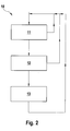
- FIG. 2 shows a block diagram 10 for explaining an embodiment of a method according to the invention.
- block 11 it is queried whether a connection to a position-determining device 4 is present and this is active.
- block 12 a query is made as to whether there is a position that lies in a predefined zone. If this is not the case, the device is activated to emit electromagnetic radiation, see block 13. Otherwise it will not be activated.
- a device for emitting electromagnetic radiation such as a radar device or short-range radar, is only activated or activatable if the device is connected to the mobile device and if the mobile device is currently logged in ("logged in") in the mobile radio network ,
- a location via mobile radio belongs to the state of the art and is used for every GSM network device registered in a radio network automatically performed. A call setup is not necessary.
- From the signal transit time of the distance of the mobile phone is determined to one or more reachable mobile stations or the transmission segments of the base stations of the radio network. This is a prerequisite that the mobile phone can be found in a radio cell at all in a call that the transmission level of base station and mobile phone is set according to the distance to the transmitter and that the automatic change to another radio cell works, i. that a so-called "hand-over function" can be realized.
- the location of a mobile phone is thus determined - and determined sufficiently accurately - first in the headquarters of the mobile network. This can be a feedback of the location or position information to the respective individual terminal.
- the resolution of the positional accuracy is usually sufficient in order to also be able to switch off near-range radar devices in the vicinity of a predefined zone, such as to trigger a radio astronomical device.
- the base station can also send a shutdown information to the terminal, so that a shutdown is performed.
- a shutdown signal may also be broadcast as a supplementary service from a transmitter, such as a GSM transmitter, or sent, for example, as a message signal such as an SMS signal.
- the location information can also be sent as an additional service from the transmitter, such as GSM transmitter to the mobile device.
- the distance to the locations of the relevant predefined zones for example of radio-astronomical zones, which are possibly stored in the vehicle, for example in the device 2 or 4, may then be the relevant predefined zones Facilities, calculated and from a shutdown signal are generated if a predetermined minimum distance is exceeded.
- the solution described above may be advantageous if location information is available as a regular available service and can thus be used to support navigation devices.
- a navigation device or a locating device can be upgraded by an addition to generate a shutdown signal, with which the Nah Titansradar device or the device 2 for emitting electromagnetic radiation can be switched off and / or pending as long as a shutdown signal, including the radar device remains switched off, Also other waveforms such as repeated single pulses or the like. will be realized.
- the near-field radar device or the electromagnetic-radiation emitting device 2 itself may have a GSM receiver which effects this shut-off function.
- a corresponding additional function can also be installed in a card-based tolling device with a GSM device accessory.
- driver information is advantageous in the event of a status change from activated to deactivated or vice versa.
Landscapes
- Engineering & Computer Science (AREA)
- Radar, Positioning & Navigation (AREA)
- Remote Sensing (AREA)
- Computer Networks & Wireless Communication (AREA)
- Physics & Mathematics (AREA)
- General Physics & Mathematics (AREA)
- Traffic Control Systems (AREA)
- Radar Systems Or Details Thereof (AREA)
- Position Fixing By Use Of Radio Waves (AREA)
Description
- Die Erfindung betrifft ein Steuerverfahren zum Steuern einer elektronisch steuerbaren Vorrichtung aufweisend ein Nahbereichsradargerät vorzugsweise in Kraftfahrzeugen insbesondere zum Aussenden elektromagnetischer Strahlen und eine solche Vorrichtung.
- Es sind elektronische Geräte bekannt, die elektromagnetische Wellen aussenden, wie beispielsweise Radargeräte. Solche Radargeräte sind unter anderem als Nahbereichsradargeräte in Kraftfahrzeugen bekannt geworden, die eingesetzt werden, um beispielsweise Hindernisse aufzuspüren, die für den Fahrer noch nicht erkennbar sind, oder um mit Seitenradar herannahende Fahrzeuge oder Hindernisse so frühzeitig zu erkennen, dass beispielsweise elektronisch gesteuert eine Gurtstraffung oder gar eine Bremsung des Fahrzeugs initiiert werden kann, bevor eine Aktion des Fahrzeugs durch den Fahrer erfolgen würde, weil er die Gefahr oder das Hindernis noch nicht erkannt hat oder nicht erkennen kann. Solche Vorrichtungen dienen daher dazu, die Sicherheit zu erhöhen, um potentielle Kollisionen frühzeitig zu erkennen und möglichst zu vermeiden - insbesondere aber deren Auswirkungen möglichst gering zu halten. Auch können solche Nahbereichsradargeräte beispielsweise mit dazu verwendet werden, teil- oder vollautomatisierte Einparkvorgänge mit zu steuern.
- Solche Nahbereichsradargeräte, die im gepulsten Betrieb im 24 GHz-Bereich (21,65 - 26,65 GHz) arbeiten dürfen, werden wegen ihrer großen Bandbreite auch als Ultra-Wide-Band Radar (UWB Radar) bezeichnet. Für ihren Betrieb sind innerhalb der Europäischen Union Beschränkungen zum Betrieb beschlossen worden, wonach bis zum 30.06.2013 nur maximal 7% aller zugelassenen Fahrzeuge pro Land mit diesen so genannten Ultra-Wide-Band Radar- Geräten im 24 GHz-Bereich (21,65 - 26,65 GHz) ausgerüstet sein dürfen. Weiterhin ist beschlossen worden, dass im Frequenzbereich von 22.21-24.00 GHz in festgelegten Sicherheitszonen zum Schutz von astronomischen Stationen solche Radargeräte nicht betrieben werden dürfen. Ab 30.07.2007 müssen sich diese Geräte zum Schutz dieser Zonen darin automatisch und ohne Fahrereinfluss selbsttätig deaktivieren.
- Die meisten Länder der Europäischen Union haben die vorgenannten Bestimmungen bereits umgesetzt und haben oder werden zu den Koordinaten und Ausdehnungen der Sicherheitszonen Ausführungen machen.
- Für Fahrer und Fahrzeug entsteht damit die Schwierigkeit des Wissens um diese Sicherheitszone und/oder ihrer sicheren Erkennung, damit im Bereich jeder einzelnen solchen Sicherheitszone das Gerät deaktiviert werden kann. Hinzu kommt, dass in vielen Fällen die Zonen noch nicht bekannt oder nicht in der Ausdehnung definiert sind. Auch ist es vorstellbar, dass später weitere heute noch unbekannte Zonen nachdefiniert werden könnten.
- Aus der Druckschrift
DE 10 2005 060 131 A1 ist eine Vorrichtung zum Aussenden elektromagnetischer Strahlen bekannt, wobei ein GPS Sensor vorgesehen ist, um die Position der elektronisch steuerbaren Vorrichtung zu ermitteln. Weiterhin ist ein Steuergerät vorgesehen, das mittels des GPS Sensors die aktuelle globale Position des Kraftfahrzeugs erhält. GPS Sensoren sind zur terrestrischen Navigation bestimmt, die jedoch den sicheren Empfang eines GPS Signals voraussetzen. Der sichere Empfang ist jedoch nicht grundsätzlich sichergestellt, und es ist bekannt, dass die Signalverbindung zu meist mehreren Satelliten insbesondere regional bedingt unterbrochen sein kann. Folglich ist eine zuverlässige Abschaltung der Vorrichtung zum Aussenden elektromagnetischer Strahlen nicht grundsätzlich sichergestellt. - Es ist die Aufgabe der vorliegenden Erfindung, ein Steuerverfahren und eine Vorrichtung zum Steuern einer elektronisch steuerbaren Vorrichtung zum Aussenden elektromagnetischer Strahlen zu schaffen, mittels welchem oder welcher die oben geschilderten Probleme beseitigt oder vermindert werden können.
- Erfindungsgemäß wird die Aufgabe bezüglich des Steuerverfahrens gelöst durch ein Steuerverfahren nach Anspruch 1.
- Auch ist es zweckmäßig, wenn die elektronisch steuerbare Vorrichtung mit einer Vorrichtung zur Positionsbestimmung verbunden ist und die Vorrichtung zur Positionsbestimmung die aktuelle Position ermittelt und bestimmt, ob die aktuelle Position in einer vordefinierten Zone liegt und der elektronisch steuerbaren Vorrichtung ein Signal zum Deaktivieren übermittelt.
- Erfindungsgemäß ist vorgesehen, dass die Vorrichtung zur Positionsbestimmung eine mobilfunkgestützte Ortung umfasst: Innerhalb eines zellularen Mobilfunknetzes wie beispielsweise GSM/GPRS und/oder UMTS wird der Ort jedes Empfängers mit für den erfindungsgemäßen Zweck hinreichender Genauigkeit ermittelt und laufend verfolgt.
- Weiterhin ist es erfindungsgemäß zweckmäßig, wenn eine solche Vorrichtung zur Positionsbestimmung mit der elektronisch steuerbaren Vorrichtung drahtlos oder drahtgebunden verbunden.
- Erfindungsgemäß ist die Vorrichtung zur Positionsbestimmung zusätzlich verbunden mit einer normalen, vorzugsweise Galileo- oder GPSgestützten Navigations- oder -Ortungsvorrichtung und auf einer mitgeführten elektronischen Karte die Bereiche elektronisch les- und auswertbar vermerkt sind, innerhalb derer die elektronisch steuerbare Vorrichtung deaktiviert bleiben sollte oder deaktiviert werden muss. Das wird dann dadurch bewirkt, dass das Navigationsgerät innerhalb dieses Sperrbereichs ein elektronisches Steuersignal abgibt, das die elektronisch steuerbare Vorrichtung deaktiviert.
- Die Definition des Sperrbereichs kann mit Vorteil entweder die direkte Entfernung zu der zu schützenden Einrichtung sein (also ein Abstand von z.B. x km) oder die Entfernung in Straßen-km (z.B. y km).
- Es ist auch erfindungsgemäß vorteilhaft, wenn mit der mobilfunkgestützten Ortung ein oder mehrere Mobilfunksender ein Signal mit ausstrahlen, mit dessen Hilfe das Mobiltelefon an Bord des Fahrzeugs ein Signal erzeugt, wird, mit dem die steuerbare Vorrichtung deaktiviert wird.
- Auch ist es vorteilhaft, wenn die Vorrichtung zur Positionsbestimmung, und damit die Mobilfunkvorrichtung, mit der elektronisch steuerbaren Vorrichtung drahtlos oder drahtgebunden verbunden ist oder die Vorrichtung zur Positionsbestimmung - ggf. also auch eine Mobilfunkeinrichtung - in die elektronisch steuerbare Vorrichtung integriert ist.
- Weiterhin ist es zweckmäßig, wenn eine Aktivierung der elektronisch steuerbaren Vorrichtung nur durchführbar ist, wenn die Vorrichtung zur Positionsbestimmung betriebsbereit ist - also im Falle der Ortung im Mobilfunknetz in diesem angemeldet ist und - falls die Information über den Sperrbereich aus dem Navigationsgerät kommen muss - dieses sich zugleich in Betriebsfunktion befindet - d.h. sich auf der digitalen Karte "eingelogged" hat.
- Die vorliegende Erfindung betrifft ferner eine elektronisch steuerbare Vorrichtung zum Aussenden elektromagnetischer Strahlen, die mit einer Vorrichtung zur Positionsbestimmung in Verbindung steht, die die kartographischen Angaben zur Definition vorbestimmter Zonen in einem Speicherelement, wie einen elektronischen Speicher und/oder einer CD-ROM und/oder einer DVD, mitführt.
- Vorteilhafte Weiterbildungen sind in den Unteransprüchen beschrieben.
- Nachstehend wird die Erfindung auf der Grundlage eines Ausführungsbeispiels anhand der Zeichnungen näher erläutert. Es zeigen in rein schematischer Darstellung:
- Fig. 1
- ein Bockschaltbild zur Erläuterung der erfindungsgemäßen Vorrichtung; und
- Fig. 2
- ein Bockschaltbild zur Erläuterung des erfindungsgemäßen Verfahrens.
- Die
Figur 1 zeigt ein Blockschaltbild 1 einer elektronisch steuerbaren Vorrichtung 2 zum Aussenden elektromagnetischer Strahlen. Dazu weist die Vorrichtung ein Sendemittel 3 auf, mittels welchem gepulste elektromagnetische Strahlen, vorzugsweise Radarstrahlen, nach dem Stand der Technik zumindest ausgesandt werden und gegebenenfalls nach Reflexion an einem Gegenstand oder Hindernis auch wieder mittels eines integrierten - ggf. aber auch eines abgesetzten - Sensors wieder empfangen werden können. Aus der Laufzeit des Signals können dann Abstandsdaten ermittelt werden, die dann von der elektronisch steuerbaren Vorrichtung zur Fahrerwarnung oder zur Steuerung von weiteren Vorrichtungen beispielsweise in einem Fahrzeug herangezogen werden, wie etwa einer Vorrichtung zur Gurtstraffung oder einer Bremsanlage zum Abbremsen eines Fahrzeugs. Auch kann beispielsweise eine Lenkung ansteuerbar sein, um einen automatisierten Einparkvorgang zu ermöglichen. - Die elektromagnetischen Radarstrahlen liegen bevorzugt im Frequenzbereich von 21,65 - 26,65 GHz, es können aber auch andere Frequenzen verwendet werden.
- Die Vorrichtung 2 ist weiterhin mit einer Vorrichtung zur Positionsbestimmung 4 verbunden, mittels welcher die Position der elektronisch steuerbaren Vorrichtung 2 ermittelt wird.
- Gemäß der Erfindung wird ein Abschalten oder eine Deaktivierung der elektronisch steuerbaren Vorrichtung 2 bzw. der Aussendung von elektromagnetischen Strahlen bewirkt, falls sich die Vorrichtung 2 in einer vordefinierten Zone befindet. Außerhalb dieser Zone ist die Vorrichtung in der Regel aktiviert, wenn sie nicht durch den Fahrer oder Halter des Fahrzeugs gezielt ausgeschaltet ist. Dabei ist unter der Aktivierung oder Deaktivierung der Vorrichtung bevorzugt das Aktivieren oder Deaktivieren der Aussendung der elektromagnetischen Strahlung zu verstehen. Bevorzugt wird eine automatische Deaktivierung durchgeführt, wobei die Vorrichtung sich selbsttätig deaktiviert oder das Aussenden der elektromagnetischen Strahlen beendet.
- Die mit der elektronisch steuerbaren Vorrichtung 2 verbundene Vorrichtung zur Positionsbestimmung 4 ermittelt automatisch bevorzugt die aktuelle Position der Vorrichtung zur Positionsbestimmung und/oder der elektronisch steuerbaren Vorrichtung 2 und übergibt der elektronisch steuerbare Vorrichtung 2 entweder ein Positionssignal, so dass die elektronisch steuerbare Vorrichtung bestimmen kann, ob die aktuelle Position in einer vordefinierten Zone liegt oder die Vorrichtung zur Positionsbestimmung 4 prüft anhand der aktuell ermittelten Position, ob die aktuelle Position in einer vordefinierten Zone liegt und gibt ein entsprechendes Signal an die elektronisch steuerbare Vorrichtung 2 weiter, so dass die elektronisch steuerbare Vorrichtung 2 sich oder die Aussendung der elektromagnetischen Strahlen deaktivieren kann. Liegt die ermittelte Position nicht in einer vordefinierten Zone, kann sich die Vorrichtung 2 oder die Aussendung der elektromagnetischen Strahlen entweder neu aktivieren (im Sinne von "einschalten") oder wieder aktivieren, wenn sie sich zuvor deaktiviert hatte.
- Die Vorrichtung zur Positionsbestimmung 4 weist vorzugsweise Mittel 5 auf, die einer Navigations- oder Ortungsvorrichtung entsprechen oder sind mit einer solchen Vorrichtung verbunden. Diese Mittel 5 können als verbindbare Einheit mit der Vorrichtung 2 oder 4 ausgebildet sein, sie können aber auch in eine Vorrichtung 2 oder 4 integriert sein.
- Mit Vorteil können die digitalen Karten der Navigationsgeräte die Information über und die Koordinaten der vordefinierten Zonen enthalten. Diese Angaben können aber auch in der elektronisch steuerbaren Vorrichtung 2 gespeichert sein.
- Dabei können diese Mittel 5 in Funkkontakt stehen mit einer Mobilfunkserver- bzw. Mobilfunkzentralanlage, welche Positionsdaten sendet, welche die Vorrichtung 4 oder die Mittel 5 empfangen, um eine Positionsbestimmung durchzuführen. Dabei können die gesendeten Daten die Position bereits enthalten oder diese Daten werden zur Positionsbestimmung verwendet. Auch können die gesendeten Daten eine Information enthalten, ob die Vorrichtung sich in einer vordefinierten Zone befindet, in welcher ein Betrieb beispielsweise eines Radargeräts nicht erlaubt ist, so dass dieses automatisiert deaktiviert werden kann.
- Insgesamt ist es vorteilhaft, wenn die Vorrichtung zur Positionsbestimmung 4, wie auch Mobilfunkvorrichtung, mit der elektronisch steuerbaren Vorrichtung 2 drahtlos oder drahtgebunden verbunden ist oder die Vorrichtung zur Positionsbestimmung 4, wie auch Mobilfunkeinrichtung, in die elektronisch steuerbare Vorrichtung 2 integriert ist.
- Gemäß eines erfindungsgemäßen Ausführungsbeispiels ist eine Aktivierung der elektronisch steuerbaren Vorrichtung 2 vorteilhafterweise nur durchführbar, wenn die Vorrichtung zur Positionsbestimmung betriebsbereit ist, d.h. mit der Mobilfunkortung aktuell in einem Mobilfunknetz angemeldet ist.
- Die
Figur 2 zeigt ein Blockschaltbild 10 zur Erläuterung eines Ausführungsbeispieles eines erfindungsgemäßen Verfahrens. In Block 11 wird abgefragt, ob eine Verbindung zu einer Positionsbestimmungsvorrichtung 4 vorliegt und diese aktiv ist. In Block 12 wird abgefragt, ob eine Position vorliegt, die in einer vordefinierten Zone liegt. Ist dies nicht der Fall, wird die Vorrichtung zur Aussendung von elektromagnetischer Strahlen aktiviert, siehe Block 13. Anderenfalls wird sie nicht aktiviert. - Bei einer Nutzung von Ortungsmöglichkeiten mittels Mobilfunk, beispielsweise mit GSM- oder UMTS- Technologie sind mehrere Varianten denkbar.
- Besonders vorteilhaft ist es, wenn eine Vorrichtung zur Aussendung von elektromagnetischen Strahlen, wie ein Radargerät oder Nahbereichsradargerät nur dann in Funktion geht oder aktivierbar ist, wenn die Vorrichtung mit dem Mobilfunkgerät verbunden ist und wenn das Mobilfunkgerät im Mobilfunknetz aktuell angemeldet ("eingelogged") ist.
- Eine Ortungsmöglichkeit über Mobilfunk gehört zum Stand der Technik und wird für jedes in einem Funknetz angemeldete GSM-Gerät automatisch durchgeführt. Ein Gesprächsaufbau ist dazu nicht nötig.
- Aus der Signallaufzeit wird der Abstand des Mobiltelefons zu einer oder mehreren erreichbaren Mobilfunkstationen bzw. den Sendesegmenten der Basisstationen des Funknetzes ermittelt. Dies ist Voraussetzung dafür, dass das Mobiltelefon in einer Funkzelle überhaupt gefunden werden kann bei einem Anruf, dass der Sendepegel von Basisstation und Mobiltelefon entsprechend dem Abstand zum Sender eingestellt wird und dass der automatische Wechsel in eine andere Funkzelle funktioniert, d.h. dass eine so genannte "Hand-over-Funktion" realisierbar ist.
- Der Ort eines Mobiltelefons wird damit - zunächst in der Zentrale des Mobilfunknetzes - hinreichend genau ermittelt und festgelegt. Damit kann eine Rückmeldung der Orts- bzw. Positionsinformation an das jeweilige einzelne Endgerät erfolgen. Die Auflösung der Positionsgenauigkeit ist in der Regel ausreichend, um damit auch ein Abschalten von Nahbereichsradar-Geräten in der Nähe einer vordefinierten Zone, wie beispielsweise um eine radioastronomische Einrichtung auslösen zu können.
- Neben der Übersendung der Positionsinformation kann die Basisstation auch eine Abschaltinformation an das Endgerät senden, so dass eine Abschaltung durchgeführt wird. Ein Abschaltsignal kann auch als Zusatzdienst von einem Sender, wie beispielsweise einem GSM-Sender, mit abgestrahlt werden oder beispielsweise als Nachrichtensignal wie beispielsweise als SMS-Signal gesendet werden.
- Die Ortungsinformation kann auch als Zusatzdienst vom Sender, wie beispielsweise GSM-Sender, an das Mobilfunkgerät gesendet werden. Im Fahrzeug kann dann der Abstand zu den beispielsweise in der Vorrichtung 2 oder 4 ggf. im Fahrzeug gespeicherten Orten der relevanten vordefinierten Zonen, beispielsweise von radioastronomischen Einrichtungen, berechnet und daraus ein Abschaltsignal generiert werden, falls ein vorgegebener Mindestabstand unterschritten ist.
- Die oben beschriebene Lösung kann vorteilhaft sein, wenn eine Ortungsinformation als regulärer verfügbarer Dienst zur Verfügung steht und damit zur Unterstützung von Navigationsgeräten eingesetzt werden kann.
- Dann kann entweder ein Navigationsgerät oder ein Ortungsgerät durch einen Zusatz ertüchtigt werden, ein Abschaltsignal zu erzeugen, mit dem das Nahbereichsradar-Gerät bzw. die Vorrichtung 2 zum Aussenden von elektromagnetischen Strahlen abgeschaltet werden kann und/oder so lange ein Abschaltsignal ansteht, auch das Radargerät abgeschaltet bleibt, Auch können andere Signalverläufe wie beispielsweise wiederholte Einzelimpulse o.ä. realisiert werden.
- Auch kann das Nahbereichsradar-Gerät oder die Vorrichtung 2 zum Aussenden von elektromagnetischen Strahlen selbst einen GSM-Empfänger aufweisen, der diese Abschaltfunktion bewirkt.
- Weiterhin kann auch in ein kartengestütztes Mautgerät mit einem GSM-Gerätezusatz eine entsprechende Zusatzfunktion mit eingebaut werden.
- Gemäß eines weiteren Erfindungsgedankens kann erreicht werden, dass bei fehlender Positionsinformation - z.B. bei ausgeschalteten Mobiltelefon - die Vorrichtung zum Aussenden von elektromagnetischen Strahlen oder das Nahbereichsradar automatisch abgeschaltet wird oder abgeschaltet bleibt. Eine automatisierte Einschaltung bzw. Aktivierung nach Vorliegen der Positionsinformationen kann vorgesehen werden.
- Vorteilhaft ist in jedem Falle eine Fahrerinformation bei einem Statuswechsel von aktiviert zu deaktiviert bzw. umgekehrt.
Claims (4)
- Steuerverfahren zum Steuern einer elektronisch steuerbaren Vorrichtung (2) aufweisend ein Nahbereichsradargerät zum Aussenden elektromagnetischer Strahlen, die mit einer Vorrichtung zur Positionsbestimmung (4) verbunden ist, bei welchem die kartographische Position der elektronisch steuerbaren Vorrichtung (2) ermittelt wird, eine Aktivierung der elektronisch steuerbaren Vorrichtung (2) nur durchführbar ist, wenn die Vorrichtung im Mobilfunknetz angemeldet ist, und dass im Falle, dass die Vorrichtung sich in einer vordefinierten Zone befindet, die Vorrichtung automatisch deaktiviert wird oder sich selbsttätig deaktiviert, wobei
die Vorrichtung zur Positionsbestimmung (4) in die elektronisch steuerbare Vorrichtung integrierbar ist und- die Vorrichtung zur Positionsbestimmung (4) der elektronisch steuerbaren Vorrichtung (2) die aktuellen Positionsdaten übergibt und die elektronisch steuerbare Vorrichtung bestimmt, ob die aktuelle Position in einer vordefinierten Zone liegt, und- eine mobilfunkgestützte Ortung basierend auf einem zellularen Mobilfunknetz und- eine satellitengestützte Navigations- oder Ortungsvorrichtung umfasst. - Steuerverfahren nach Anspruch 1, dadurch gekennzeichnet, dass die elektronisch steuerbare Vorrichtung (2) mit einer Vorrichtung zur Positionsbestimmung (4) verbunden ist und die Vorrichtung zur Positionsbestimmung (4) die aktuelle Position ermittelt und bestimmt, ob die aktuelle Position in einer vordefinierten Zone liegt und der elektronisch steuerbaren Vorrichtung ein Signal zum Deaktivieren übermittelt.
- Steuerverfahren nach einem der vorhergehenden Ansprüche, dadurch gekennzeichnet, dass die satellitengestützte Navigations- oder Ortungsvorrichtung eine Galileo- oder GPS- gestützte Navigations- oder Ortungsvorrichtung ist.
- Steuerverfahren nach Anspruch 4, dadurch gekennzeichnet, dass eine Vorrichtung zur Positionsbestimmung (4), wie auch Mobilfunkvorrichtung, mit der elektronisch steuerbaren Vorrichtung drahtlos oder drahtgebunden verbunden ist.
Applications Claiming Priority (1)
| Application Number | Priority Date | Filing Date | Title |
|---|---|---|---|
| DE102007046766A DE102007046766A1 (de) | 2007-09-28 | 2007-09-28 | Steuerverfahren und Vorrichtung zum automatischen Abschalten insbesondere von Nahbereichsradar |
Publications (3)
| Publication Number | Publication Date |
|---|---|
| EP2042887A2 EP2042887A2 (de) | 2009-04-01 |
| EP2042887A3 EP2042887A3 (de) | 2009-09-02 |
| EP2042887B1 true EP2042887B1 (de) | 2011-10-19 |
Family
ID=40175095
Family Applications (1)
| Application Number | Title | Priority Date | Filing Date |
|---|---|---|---|
| EP08105144A Not-in-force EP2042887B1 (de) | 2007-09-28 | 2008-08-27 | Steuerverfahren und Vorrichtung zum automatischen Abschalten insbesondere von Nahbereichsradar |
Country Status (3)
| Country | Link |
|---|---|
| EP (1) | EP2042887B1 (de) |
| AT (1) | ATE529760T1 (de) |
| DE (1) | DE102007046766A1 (de) |
Families Citing this family (1)
| Publication number | Priority date | Publication date | Assignee | Title |
|---|---|---|---|---|
| JP5574579B2 (ja) | 2008-05-29 | 2014-08-20 | アルパイン株式会社 | レーダ監視装置 |
Family Cites Families (5)
| Publication number | Priority date | Publication date | Assignee | Title |
|---|---|---|---|---|
| US6201493B1 (en) * | 1999-05-28 | 2001-03-13 | Lucent Technologies Inc. | Radar detector arrangement |
| US7239887B1 (en) * | 2000-10-25 | 2007-07-03 | Trimble Navigation Limited | Mobile control apparatus |
| JP3783643B2 (ja) * | 2002-03-29 | 2006-06-07 | セイコーエプソン株式会社 | 携帯端末装置 |
| DE102004017720A1 (de) | 2004-04-10 | 2005-10-27 | Robert Bosch Gmbh | Radarsensor |
| DE102005060131A1 (de) | 2005-12-16 | 2007-06-21 | Bayerische Motoren Werke Ag | Vorrichtung zur Erfassung von Objekten im Nahbereich eines Kraftfahrzeugs |
-
2007
- 2007-09-28 DE DE102007046766A patent/DE102007046766A1/de not_active Withdrawn
-
2008
- 2008-08-27 EP EP08105144A patent/EP2042887B1/de not_active Not-in-force
- 2008-08-27 AT AT08105144T patent/ATE529760T1/de active
Also Published As
| Publication number | Publication date |
|---|---|
| EP2042887A2 (de) | 2009-04-01 |
| DE102007046766A1 (de) | 2009-04-02 |
| ATE529760T1 (de) | 2011-11-15 |
| EP2042887A3 (de) | 2009-09-02 |
Similar Documents
| Publication | Publication Date | Title |
|---|---|---|
| DE60311039T2 (de) | Fahrzeugortungssystem durch Benutzung eines Ad-hoc-Netzwerks | |
| DE112006003060B4 (de) | Verkehrsinformationssystem zum Aktualisieren von Verkehrsdaten unter Verwendung von Sondenfahrzeugen mit Außensensoren | |
| US9066464B2 (en) | Moving geofence for machine tracking in agriculture | |
| CN113460051A (zh) | 合作式变道控制方法、装置及设备 | |
| DE102018120336A1 (de) | Kommunikation von infrastrukturinformationen an ein fahrzeug über bodendurchdringungsradar | |
| CN113299096A (zh) | 合作式交叉路口通行控制方法、装置及设备 | |
| DE10253192A1 (de) | Verfahren und Vorrichtung zur Vermeidung von Kollisionen | |
| DE102007049603A1 (de) | Kollisionsvermeidungssystem und -verfahren zum Unterstützen einer Fahrzeugrückwärtsbewegung | |
| DE102009015513A1 (de) | Ortungssignal für Einsatzkräfte | |
| EP2193513B1 (de) | Vorrichtung und verfahren zur erkennung von fahrzeugen und deren annäherungswinkel | |
| WO2006007943A1 (de) | Verfahren zum betreiben eines fahrsystems eines kraftfahrzeugs und fahrsystem zur durchführung des verfahrens | |
| WO2009043644A1 (de) | Steuerverfahren und system | |
| EP2577639B1 (de) | Annäherungswarnsystem und verfahren zur erkennung der annäherung beweglicher objekte | |
| EP3065447A1 (de) | Verfahren und Testgerät zum Testen eines mobilfunkgestützten Notrufsystems | |
| EP3174772B1 (de) | Vorrichtung zum anordnen an einem kraftfahrzeug | |
| WO2016120236A1 (de) | Applikationsgesteuertes geo-beamforming | |
| DE102018102112A1 (de) | Techniken zur Kollisionsvermeidung zwischen unbemannten Luftfahrzeugen mittels Gerät-zu-Gerät Funkkommunikation | |
| US6539307B1 (en) | System and method for monitoring interaction between objects and multiple mobile units | |
| DE19733460C1 (de) | Diebstahlsicherung | |
| WO2009090185A2 (de) | Verfahren und system zur eindringverhinderung eines beweglichen objekts in einen geschützten abschnitt | |
| EP2042888B1 (de) | Steuerverfahren und Vorrichtung zum automatischen Abschalten von Nahbereichsradar | |
| EP2042887B1 (de) | Steuerverfahren und Vorrichtung zum automatischen Abschalten insbesondere von Nahbereichsradar | |
| DE19602053A1 (de) | Einrichtung zur Überwachung des Abstandes zweier Objekte | |
| DE10316451A1 (de) | Sicherheitssystem für den Straßenverkehr | |
| DE102004021186A1 (de) | Verfahren und System zur Verkehrsüberwachung und/oder zur dynamischen Verkehrsbeeinflussung |
Legal Events
| Date | Code | Title | Description |
|---|---|---|---|
| PUAI | Public reference made under article 153(3) epc to a published international application that has entered the european phase |
Free format text: ORIGINAL CODE: 0009012 |
|
| AK | Designated contracting states |
Kind code of ref document: A2 Designated state(s): AT BE BG CH CY CZ DE DK EE ES FI FR GB GR HR HU IE IS IT LI LT LU LV MC MT NL NO PL PT RO SE SI SK TR |
|
| AX | Request for extension of the european patent |
Extension state: AL BA MK RS |
|
| PUAL | Search report despatched |
Free format text: ORIGINAL CODE: 0009013 |
|
| AK | Designated contracting states |
Kind code of ref document: A3 Designated state(s): AT BE BG CH CY CZ DE DK EE ES FI FR GB GR HR HU IE IS IT LI LT LU LV MC MT NL NO PL PT RO SE SI SK TR |
|
| AX | Request for extension of the european patent |
Extension state: AL BA MK RS |
|
| RIC1 | Information provided on ipc code assigned before grant |
Ipc: G01S 1/00 20060101ALI20090724BHEP Ipc: G01S 13/86 20060101AFI20090108BHEP Ipc: G01S 7/40 20060101ALI20090724BHEP |
|
| 17P | Request for examination filed |
Effective date: 20100302 |
|
| 17Q | First examination report despatched |
Effective date: 20100326 |
|
| AKX | Designation fees paid |
Designated state(s): AT BE BG CH CY CZ DE DK EE ES FI FR GB GR HR HU IE IS IT LI LT LU LV MC MT NL NO PL PT RO SE SI SK TR |
|
| GRAP | Despatch of communication of intention to grant a patent |
Free format text: ORIGINAL CODE: EPIDOSNIGR1 |
|
| RIC1 | Information provided on ipc code assigned before grant |
Ipc: G01S 13/86 20060101AFI20110429BHEP Ipc: G01S 19/00 20100101ALI20110429BHEP Ipc: G01S 7/40 20060101ALI20110429BHEP |
|
| GRAS | Grant fee paid |
Free format text: ORIGINAL CODE: EPIDOSNIGR3 |
|
| GRAA | (expected) grant |
Free format text: ORIGINAL CODE: 0009210 |
|
| AK | Designated contracting states |
Kind code of ref document: B1 Designated state(s): AT BE BG CH CY CZ DE DK EE ES FI FR GB GR HR HU IE IS IT LI LT LU LV MC MT NL NO PL PT RO SE SI SK TR |
|
| REG | Reference to a national code |
Ref country code: GB Ref legal event code: FG4D Free format text: NOT ENGLISH |
|
| REG | Reference to a national code |
Ref country code: CH Ref legal event code: EP |
|
| REG | Reference to a national code |
Ref country code: IE Ref legal event code: FG4D |
|
| REG | Reference to a national code |
Ref country code: DE Ref legal event code: R096 Ref document number: 502008005232 Country of ref document: DE Effective date: 20111215 |
|
| REG | Reference to a national code |
Ref country code: NL Ref legal event code: VDEP Effective date: 20111019 |
|
| LTIE | Lt: invalidation of european patent or patent extension |
Effective date: 20111019 |
|
| PG25 | Lapsed in a contracting state [announced via postgrant information from national office to epo] |
Ref country code: NO Free format text: LAPSE BECAUSE OF FAILURE TO SUBMIT A TRANSLATION OF THE DESCRIPTION OR TO PAY THE FEE WITHIN THE PRESCRIBED TIME-LIMIT Effective date: 20120119 Ref country code: LT Free format text: LAPSE BECAUSE OF FAILURE TO SUBMIT A TRANSLATION OF THE DESCRIPTION OR TO PAY THE FEE WITHIN THE PRESCRIBED TIME-LIMIT Effective date: 20111019 Ref country code: IS Free format text: LAPSE BECAUSE OF FAILURE TO SUBMIT A TRANSLATION OF THE DESCRIPTION OR TO PAY THE FEE WITHIN THE PRESCRIBED TIME-LIMIT Effective date: 20120219 |
|
| REG | Reference to a national code |
Ref country code: IE Ref legal event code: FD4D |
|
| PG25 | Lapsed in a contracting state [announced via postgrant information from national office to epo] |
Ref country code: PT Free format text: LAPSE BECAUSE OF FAILURE TO SUBMIT A TRANSLATION OF THE DESCRIPTION OR TO PAY THE FEE WITHIN THE PRESCRIBED TIME-LIMIT Effective date: 20120220 Ref country code: SE Free format text: LAPSE BECAUSE OF FAILURE TO SUBMIT A TRANSLATION OF THE DESCRIPTION OR TO PAY THE FEE WITHIN THE PRESCRIBED TIME-LIMIT Effective date: 20111019 Ref country code: NL Free format text: LAPSE BECAUSE OF FAILURE TO SUBMIT A TRANSLATION OF THE DESCRIPTION OR TO PAY THE FEE WITHIN THE PRESCRIBED TIME-LIMIT Effective date: 20111019 Ref country code: LV Free format text: LAPSE BECAUSE OF FAILURE TO SUBMIT A TRANSLATION OF THE DESCRIPTION OR TO PAY THE FEE WITHIN THE PRESCRIBED TIME-LIMIT Effective date: 20111019 Ref country code: SI Free format text: LAPSE BECAUSE OF FAILURE TO SUBMIT A TRANSLATION OF THE DESCRIPTION OR TO PAY THE FEE WITHIN THE PRESCRIBED TIME-LIMIT Effective date: 20111019 Ref country code: GR Free format text: LAPSE BECAUSE OF FAILURE TO SUBMIT A TRANSLATION OF THE DESCRIPTION OR TO PAY THE FEE WITHIN THE PRESCRIBED TIME-LIMIT Effective date: 20120120 Ref country code: HR Free format text: LAPSE BECAUSE OF FAILURE TO SUBMIT A TRANSLATION OF THE DESCRIPTION OR TO PAY THE FEE WITHIN THE PRESCRIBED TIME-LIMIT Effective date: 20111019 |
|
| PG25 | Lapsed in a contracting state [announced via postgrant information from national office to epo] |
Ref country code: CY Free format text: LAPSE BECAUSE OF FAILURE TO SUBMIT A TRANSLATION OF THE DESCRIPTION OR TO PAY THE FEE WITHIN THE PRESCRIBED TIME-LIMIT Effective date: 20111019 |
|
| PG25 | Lapsed in a contracting state [announced via postgrant information from national office to epo] |
Ref country code: DK Free format text: LAPSE BECAUSE OF FAILURE TO SUBMIT A TRANSLATION OF THE DESCRIPTION OR TO PAY THE FEE WITHIN THE PRESCRIBED TIME-LIMIT Effective date: 20111019 Ref country code: CZ Free format text: LAPSE BECAUSE OF FAILURE TO SUBMIT A TRANSLATION OF THE DESCRIPTION OR TO PAY THE FEE WITHIN THE PRESCRIBED TIME-LIMIT Effective date: 20111019 Ref country code: EE Free format text: LAPSE BECAUSE OF FAILURE TO SUBMIT A TRANSLATION OF THE DESCRIPTION OR TO PAY THE FEE WITHIN THE PRESCRIBED TIME-LIMIT Effective date: 20111019 Ref country code: SK Free format text: LAPSE BECAUSE OF FAILURE TO SUBMIT A TRANSLATION OF THE DESCRIPTION OR TO PAY THE FEE WITHIN THE PRESCRIBED TIME-LIMIT Effective date: 20111019 Ref country code: IE Free format text: LAPSE BECAUSE OF FAILURE TO SUBMIT A TRANSLATION OF THE DESCRIPTION OR TO PAY THE FEE WITHIN THE PRESCRIBED TIME-LIMIT Effective date: 20111019 Ref country code: BG Free format text: LAPSE BECAUSE OF FAILURE TO SUBMIT A TRANSLATION OF THE DESCRIPTION OR TO PAY THE FEE WITHIN THE PRESCRIBED TIME-LIMIT Effective date: 20120119 |
|
| PLBE | No opposition filed within time limit |
Free format text: ORIGINAL CODE: 0009261 |
|
| STAA | Information on the status of an ep patent application or granted ep patent |
Free format text: STATUS: NO OPPOSITION FILED WITHIN TIME LIMIT |
|
| PG25 | Lapsed in a contracting state [announced via postgrant information from national office to epo] |
Ref country code: IT Free format text: LAPSE BECAUSE OF FAILURE TO SUBMIT A TRANSLATION OF THE DESCRIPTION OR TO PAY THE FEE WITHIN THE PRESCRIBED TIME-LIMIT Effective date: 20111019 Ref country code: RO Free format text: LAPSE BECAUSE OF FAILURE TO SUBMIT A TRANSLATION OF THE DESCRIPTION OR TO PAY THE FEE WITHIN THE PRESCRIBED TIME-LIMIT Effective date: 20111019 Ref country code: PL Free format text: LAPSE BECAUSE OF FAILURE TO SUBMIT A TRANSLATION OF THE DESCRIPTION OR TO PAY THE FEE WITHIN THE PRESCRIBED TIME-LIMIT Effective date: 20111019 |
|
| 26N | No opposition filed |
Effective date: 20120720 |
|
| REG | Reference to a national code |
Ref country code: DE Ref legal event code: R097 Ref document number: 502008005232 Country of ref document: DE Effective date: 20120720 |
|
| BERE | Be: lapsed |
Owner name: ROBERT BOSCH G.M.B.H. Effective date: 20120831 |
|
| REG | Reference to a national code |
Ref country code: CH Ref legal event code: PL |
|
| PG25 | Lapsed in a contracting state [announced via postgrant information from national office to epo] |
Ref country code: MC Free format text: LAPSE BECAUSE OF NON-PAYMENT OF DUE FEES Effective date: 20120831 |
|
| GBPC | Gb: european patent ceased through non-payment of renewal fee |
Effective date: 20120827 |
|
| PG25 | Lapsed in a contracting state [announced via postgrant information from national office to epo] |
Ref country code: CH Free format text: LAPSE BECAUSE OF NON-PAYMENT OF DUE FEES Effective date: 20120831 Ref country code: ES Free format text: LAPSE BECAUSE OF FAILURE TO SUBMIT A TRANSLATION OF THE DESCRIPTION OR TO PAY THE FEE WITHIN THE PRESCRIBED TIME-LIMIT Effective date: 20120130 Ref country code: LI Free format text: LAPSE BECAUSE OF NON-PAYMENT OF DUE FEES Effective date: 20120831 |
|
| PG25 | Lapsed in a contracting state [announced via postgrant information from national office to epo] |
Ref country code: BE Free format text: LAPSE BECAUSE OF NON-PAYMENT OF DUE FEES Effective date: 20120831 |
|
| PG25 | Lapsed in a contracting state [announced via postgrant information from national office to epo] |
Ref country code: FI Free format text: LAPSE BECAUSE OF FAILURE TO SUBMIT A TRANSLATION OF THE DESCRIPTION OR TO PAY THE FEE WITHIN THE PRESCRIBED TIME-LIMIT Effective date: 20111019 |
|
| PG25 | Lapsed in a contracting state [announced via postgrant information from national office to epo] |
Ref country code: GB Free format text: LAPSE BECAUSE OF NON-PAYMENT OF DUE FEES Effective date: 20120827 |
|
| PG25 | Lapsed in a contracting state [announced via postgrant information from national office to epo] |
Ref country code: MT Free format text: LAPSE BECAUSE OF FAILURE TO SUBMIT A TRANSLATION OF THE DESCRIPTION OR TO PAY THE FEE WITHIN THE PRESCRIBED TIME-LIMIT Effective date: 20111019 |
|
| PG25 | Lapsed in a contracting state [announced via postgrant information from national office to epo] |
Ref country code: TR Free format text: LAPSE BECAUSE OF FAILURE TO SUBMIT A TRANSLATION OF THE DESCRIPTION OR TO PAY THE FEE WITHIN THE PRESCRIBED TIME-LIMIT Effective date: 20111019 |
|
| PG25 | Lapsed in a contracting state [announced via postgrant information from national office to epo] |
Ref country code: LU Free format text: LAPSE BECAUSE OF NON-PAYMENT OF DUE FEES Effective date: 20120827 |
|
| PG25 | Lapsed in a contracting state [announced via postgrant information from national office to epo] |
Ref country code: HU Free format text: LAPSE BECAUSE OF FAILURE TO SUBMIT A TRANSLATION OF THE DESCRIPTION OR TO PAY THE FEE WITHIN THE PRESCRIBED TIME-LIMIT Effective date: 20080827 |
|
| REG | Reference to a national code |
Ref country code: AT Ref legal event code: MM01 Ref document number: 529760 Country of ref document: AT Kind code of ref document: T Effective date: 20130827 |
|
| PG25 | Lapsed in a contracting state [announced via postgrant information from national office to epo] |
Ref country code: AT Free format text: LAPSE BECAUSE OF NON-PAYMENT OF DUE FEES Effective date: 20130827 |
|
| REG | Reference to a national code |
Ref country code: FR Ref legal event code: PLFP Year of fee payment: 9 |
|
| REG | Reference to a national code |
Ref country code: FR Ref legal event code: PLFP Year of fee payment: 10 |
|
| REG | Reference to a national code |
Ref country code: FR Ref legal event code: PLFP Year of fee payment: 11 |
|
| PGFP | Annual fee paid to national office [announced via postgrant information from national office to epo] |
Ref country code: FR Payment date: 20190822 Year of fee payment: 12 |
|
| PGFP | Annual fee paid to national office [announced via postgrant information from national office to epo] |
Ref country code: DE Payment date: 20191021 Year of fee payment: 12 |
|
| REG | Reference to a national code |
Ref country code: DE Ref legal event code: R119 Ref document number: 502008005232 Country of ref document: DE |
|
| PG25 | Lapsed in a contracting state [announced via postgrant information from national office to epo] |
Ref country code: DE Free format text: LAPSE BECAUSE OF NON-PAYMENT OF DUE FEES Effective date: 20210302 Ref country code: FR Free format text: LAPSE BECAUSE OF NON-PAYMENT OF DUE FEES Effective date: 20200831 |