EP2042671A2 - Handle mounting and fitting with handle mounting - Google Patents
Handle mounting and fitting with handle mounting Download PDFInfo
- Publication number
- EP2042671A2 EP2042671A2 EP08014034A EP08014034A EP2042671A2 EP 2042671 A2 EP2042671 A2 EP 2042671A2 EP 08014034 A EP08014034 A EP 08014034A EP 08014034 A EP08014034 A EP 08014034A EP 2042671 A2 EP2042671 A2 EP 2042671A2
- Authority
- EP
- European Patent Office
- Prior art keywords
- handle
- actuating pin
- adapter
- rosette
- receiving
- Prior art date
- Legal status (The legal status is an assumption and is not a legal conclusion. Google has not performed a legal analysis and makes no representation as to the accuracy of the status listed.)
- Granted
Links
Images

Classifications
-
- E—FIXED CONSTRUCTIONS
- E05—LOCKS; KEYS; WINDOW OR DOOR FITTINGS; SAFES
- E05B—LOCKS; ACCESSORIES THEREFOR; HANDCUFFS
- E05B3/00—Fastening knobs or handles to lock or latch parts
- E05B3/06—Fastening knobs or handles to lock or latch parts by means arranged in or on the rose or escutcheon
-
- E—FIXED CONSTRUCTIONS
- E05—LOCKS; KEYS; WINDOW OR DOOR FITTINGS; SAFES
- E05B—LOCKS; ACCESSORIES THEREFOR; HANDCUFFS
- E05B15/00—Other details of locks; Parts for engagement by bolts of fastening devices
- E05B15/0053—Other details of locks; Parts for engagement by bolts of fastening devices means providing a stable, i.e. indexed, position of lock parts
-
- E—FIXED CONSTRUCTIONS
- E05—LOCKS; KEYS; WINDOW OR DOOR FITTINGS; SAFES
- E05B—LOCKS; ACCESSORIES THEREFOR; HANDCUFFS
- E05B3/00—Fastening knobs or handles to lock or latch parts
- E05B3/04—Fastening the knob or the handle shank to the spindle by screws, springs or snap bolts
-
- E—FIXED CONSTRUCTIONS
- E05—LOCKS; KEYS; WINDOW OR DOOR FITTINGS; SAFES
- E05B—LOCKS; ACCESSORIES THEREFOR; HANDCUFFS
- E05B15/00—Other details of locks; Parts for engagement by bolts of fastening devices
- E05B15/0033—Spindles for handles, e.g. square spindles
Definitions
- the invention relates to a device for securely attaching a handle actuating pin in a mounting opening of a handle according to the preamble of claim 1. Further, the invention relates to a fitting with a handle and a rosette device with which the handle is connectable, according to the preamble of claim. 9 ,
- the handles to operate doors, windows, especially mechanical door traps, window latch mechanisms or the like are well known in the art.
- the handles have for this purpose a connection piece for the rotationally fixed coupling with the lock, the locking mechanism, etc.
- the connector is hereinafter referred to as handle actuating pin, which is also commonly known as a mandrel.
- the handle actuating pin is usually designed as a square pin.
- the handle actuating pins for doors and for windows have different dimensions, with window square pins usually having an edge dimension of 7 mm and door square pins usually having an edge dimension of 9 mm.
- the square pin is permanently fixed in the handle, for example, glued, and has a fixed projection measure, with which it protrudes from the handle.
- the window handle on a square hole with 7 mm edge length.
- window handles are further known, which are designed so that they can be rested in each 90 ° increments to close the window either to tilt or open.
- These window handles have for this purpose a drive plate, which has corresponding locking devices, which interact, for example, with locking units of a rosette device.
- window and door handles are not integrated into a modular system: fittings with such window handles must therefore be factory produced in a separate production line.
- fittings constructed in this way can only be used for windows or only for doors, so that there are separate production lines for windows and doors.
- the invention includes the technical teaching that in a device for securely attaching a handle actuating pin to a mounting opening of a handle, in particular a door or window handle, at least one adapter is provided, which has a fastening part for mounting in the mounting hole and a receiving part for Receiving the handle actuating pin, wherein the receiving part has means for axially secured receiving the handle actuating pin.
- the adapter is designed so that it is connectable at its opposite sides in each case with different components.
- the components can vary in terms of shape, dimensions and the like.
- the fastening part of the adapter can be attached to a door handle.
- the door handle has an attachment opening into which the attachment part of the adapter can be inserted.
- the attachment opening is preferably designed to receive a non-rotationally symmetrical actuating pin, preferably a square pin, in particular a square door pin. Usual dimensions of such a square pin are 9 mm x 9 mm edge length.
- the fastening part is designed as such a square section, which is designed to be complementary to the fastening opening.
- the attachment opening is designed accordingly as a square hole.
- the adapter is designed so that different actuation pins, usually square pins, for example, square socket pins or Mosvierkantriche can use the adapter with the corresponding handle, a door handle or a window handle.
- Door handles usually have a receptacle for Matkierkantite, which have larger dimensions than corresponding window receptacles in window handles.
- Square pins for windows which have correspondingly smaller dimensions than door square pins, can also be used for door handles.
- the other way around can be used with a suitable adapter Schovierkantriche for window handles.
- all Mosgriffaus exiten can be used as window handles and vice versa.
- the actuating pin is rotatably connected to the handle, so that an applied by a user on the handle for actuation rotational movement is transmitted to the actuating pin and thus to a door latch, a window latch mechanism or the like.
- the means comprise a clamping device for receiving the handle actuating pin displaceably secured.
- the formed for example as a square pin actuating pin Suburb can be easily plugged into the receiving part of the adapter, without tools are required. When inserting the square pin is jammed by the clamping device and thus secured in its axial direction.
- the clamping device may be formed on the adapter and / or on the attachment opening.
- the adapter comprises a latching element which, in cooperation with complementary latching projections of a rosette device, enables predefined latching positions of the handle actuating pin or of the handle.
- the receiving part of the adapter can be designed as a drive plate with a corresponding recess for receiving the actuating pin.
- the drive plate preferably has four latching elements in order to let it engage four times during a rotation of the handle, preferably offset by 90 °.
- the latching elements of the adapter cooperate with corresponding latching projections of the rosette device.
- the clamping device and the latching element are integrally formed. This makes it possible to realize a relatively small adapter and installation work is reduced.
- the clamping device is designed as a receiving opening with clamping means which clamps the handle actuating pin displaceably secured.
- the actuating pin is simply inserted into the receiving opening and clamped by the clamping means.
- jamming at a plurality of offset in the axial direction of the actuating pin clamping positions is possible. If necessary, the actuating pin can be further inserted into the receiving opening and clamped again.
- clamping means comprise a tapered portion of the receiving opening to the handle actuating pin slidably secured record. With increasing insertion depth of the actuating pin whose fuse is thus reinforced in the adapter.
- the clamping means comprise a resilient portion which causes a gripping of the handle actuating pin when receiving the handle actuating pin in the installed state in the rosette device.
- the resilient portion can be realized by suitable choice of material of the adapter or by additional components such as springs.
- the attachment member is formed as a complementary to the mounting opening Vierkantringvorsprung.
- the fastening part and the fastening openings can in principle have any desired shape.
- the fastening part has approximately the shape of a door actuating pin.
- window actuating pins can be easily used in existing door fittings.
- the invention further includes the technical teaching that in a fitting, in particular a door and / or window fitting, with a handle and a rosette device with which the handle is connectable, in particular latched, the handle connected via an adapter according to the invention with the rosette device is.
- the adapter connects depending on the shape of any actuation pins with different handles.
- the adapter has latch notches, which in the assembled state interact with latching projections of the rosette device by at least one latching position to realize the handle. As a result, predeterminable locking positions can be set.
- any door handle or door handle can be mounted from existing programs on a corresponding rosette device. There are thus no different production programs for window handles and door handles necessary.
- a door handle can engage, preferably four times, for example, a horizontal position or a vertical position of the door handle is held by the detents.
- the latching elements or the latching projections may be formed as resilient elements, for example as resilient webs.
- the resilient elements can be designed so that they require a predetermined latching force or disengaging force.
- the adapter is made of a suitable material such as plastic, precious metal, aluminum and the like.
- the adapter is made of such a material which has a low coefficient of friction upon actuation of the handle.
- the customary for the door handles dimensions in particular the square dimensions, for example, of 9 mm x 9 mm, can be reduced to a required for example for window handles measure of about 7 mm x 7 mm.
- the variable axial securing a projecting projection dimension of the actuating pin suburb can be adapted directly to the customer requirements.
- the rosette device may have a longer guide, so that heavier or larger door handles are used.
- the guides can be visually laminated accordingly.
- Fig. 1 to 6 all show the same embodiment in different views and are therefore described together.
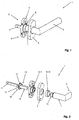
- Fig. 1 shows a perspective view of a fitting 1 with a device 2 for securely attaching a handle actuating pin 9 to a handle 3 in a nearly completely assembled state.
- the fitting 1 comprises, in addition to the handle 3, a rosette device 4 with which the handle 3 is connected, in particular latched.
- the rosette device 4 has a rosette main body 5 and a main body cover 6 for covering the rosette main body 5.
- the handle 3 is guided on its handle neck 7 in a guide 8. From the handle 3 protrudes designed as a square pin handle actuating pin 9 protrudes.
- Fig. 2 the structure can be seen more clearly by the representation in an exploded view.
- the handle 3 on its handle neck 7 a handle neck 10, over which the handle is guided in the guide 8.
- the guide 8 comprises a guide part 11, which is formed on the rosette main body 5, and a guide cover 12, which conceals the guide member 11 optically outward.
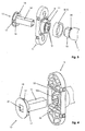
- the device 2 according to the invention comprises an adapter 13, via which the handle actuating pin 9 with the rosette device 4 and the handle 3 is connectable.
- the adapter 13 comprises a fastening part 14 and a receiving part 15.
- the fastening part 14 is formed as Vierkantringvorsprung and fits into a not visible here attachment opening of the handle 3.
- the receiving part 15 is adapted to receive the handle actuating pin 9 axially secured.
- a drive plate 16 is formed. On the drive plate 16 locking elements 17 are formed, which in FIG. 3 and FIG. 4 can be seen more clearly.
- visible locking elements 17 are formed in the illustrated embodiment as Rasteinkerbitch which about the the same angle, in this case about 90 °, offset from each other.
- the drive plate 16 has an approximately annular projection 18 in which the fastening part 14 of the adapter 13 is arranged spaced apart.
- the fastening part 14 protrudes in the direction of the handle 3 on the projection 18.
- the inner contour of the projection 18 is flattened at two points, so that the inner contour is not rotationally symmetrical. These two flattened locations correspond to two likewise flattened sections on the handle neck 10, so that they can cooperate against a rotation of the handle 3 relative to the adapter 13.
- locking hooks 19 are formed, which cooperate in the assembled state with a groove 20 of the handle neck approach 10 and avoid accidental pulling out of the handle 3 by an axial securing.
- the receiving part 15 of the adapter 13 has a receiving opening 21 to receive the handle actuating pin 9 therein.
- the contours of handle actuating pin 9 and receiving opening 21 are formed correspondingly complementary, in the present case as a square or square hole.
- Fig. 4 Also good in Fig. 4 can be seen locking projections 22 on the rosette base 5, which cooperate with the locking elements 17 of the adapter 13 in the installed state.
- the latching projections 22 are formed as resilient webs. The webs shown have approximately in the middle of a survey that can snap into the latch notch 17. In the present case, two opposite latching projections 22 are formed on the adapter 13.
- the fastening part 14 of the adapter 13 is formed as a square projection.
- the outer contour of the square projection is approximately complementary formed to the contour of the attachment opening 10a of the handle 3, so that the square projection is inserted into the attachment opening 10a. Since the contours of both the fastening part 14 and the fastening opening 10 a are not formed rotationally symmetrical, a rotationally secure arrangement of the adapter 13 with respect to the handle 3 can be realized.
- Fig. 5 can be the assembly of the fitting 1 well.
- the handle 3 is inserted into the rosette main body 5 as far as the in Fig. 5 not visible latch hooks 19 of the rosette base body 5 in also in Fig. 5 engage invisible groove 20 of the handle 3.
- the adapter 13 with the in Fig. 3 visible fastening part 14 inserted through the guide 8 of the rosette device 4 in the mounting hole 10 a of the handle 3.
- the flattened portions of the adapter 13 align with the flattened portions of the handle 3 and allow a backlash-free and non-rotating seat Fig. 3 Rasteinkerbept shown 17 of the adapter 13 press the in Fig. 4 shown latching projections 22 of the rosette base 5 to the outside and give the adapter 13 a bias.
- the handle actuating pin 9 is now driven into the receiving opening 21 of the adapter 13.
- a force is required, which is definable so that the handle actuating pin 9 can not be moved in the installed state.
- a clamping device may be provided, which in particular has clamping means in or on the receiving opening 21. These clamping means can secure the handle actuating pin 9 axially.
- the main body cover 6 is now attached to the rosette base 5.
- clip hooks 23 provided on the rosette base body 5 prevent the main body cover 6 unintentionally releases from the rosette main body 5 by the clip hooks 23 snap into recesses 24 of the main body cover 6.
- the base body cover 6 has a notch 25 into which a tool for disassembling the main body cover 6 can be introduced from the rosette base body 5.
- Fig. 6 shows a sectional view of the assembled fitting 1.
- the adapter 13 is flush with the rosette device 4 finally received in the rosette device 4.
- the handle actuating pin 9 projects beyond the rosette device 4 or the adapter 13 by a protrusion dimension X.
- This projection dimension X can be varied in the installed state by the handle actuating pin 9 is pushed further in the direction of handle 3 or pulled out opposite. If necessary, the corresponding clamping means must be solved for this purpose.
- Anschraubbohritch 26 are provided in the rosette base 5 . These are used for mounting on a window, a door or the like.
Abstract
Description
Die Erfindung betrifft eine Vorrichtung zur sicheren Anbringung eines Griff-Betätigungsstiftes in einer Befestigungsöffnung eines Griffes gemäß dem Oberbegriff des Anspruches 1. Weiter betrifft die Erfindung einen Beschlag mit einem Griff und einer Rosetteneinrichtung, mit welcher der Griff verbindbar ist, gemäß dem Oberbegriff des Anspruches 9.The invention relates to a device for securely attaching a handle actuating pin in a mounting opening of a handle according to the preamble of
(Betätigungs-)Griffe, um Türen, Fenster, insbesondere mechanische Türfallen, Fensterriegelmechanismen oder dergleichen zu bedienen, sind allgemein.bekannt. Die Griffe weisen zu diesem Zweck ein Anschlussstück zur drehfesten Kopplung mit dem Schloss, dem Riegelmechanismus etc. auf. Das Anschlussstück wird im Folgenden als Griff-Betätigungsstift bezeichnet, der allgemein auch als Dorn bekannt ist. Der Griff-Betätigungsstift ist üblicherweise als Vierkantstift gestaltet. Dabei weisen die Griff-Betätigungsstifte für Türen und für Fenster unterschiedliche Abmaße auf, wobei Fenster-Vierkantstifte üblicherweise ein Kantenmaß von 7 mm und Tür-Vierkantstifte üblicherweise ein Kantenmaß von 9 mm aufweisen können.(Actuator) handles to operate doors, windows, especially mechanical door traps, window latch mechanisms or the like are well known in the art. The handles have for this purpose a connection piece for the rotationally fixed coupling with the lock, the locking mechanism, etc. The connector is hereinafter referred to as handle actuating pin, which is also commonly known as a mandrel. The handle actuating pin is usually designed as a square pin. The handle actuating pins for doors and for windows have different dimensions, with window square pins usually having an edge dimension of 7 mm and door square pins usually having an edge dimension of 9 mm.
Der Vierkantstift wird dauerhaft in dem Griff befestigt, beispielsweise eingeklebt, und weist ein festes Vorsprungsmaß auf, mit welchem er aus dem Griff hervorsteht. Im Stand der Technik weist der Fenstergriff ein Vierkantloch mit 7 mm Kantenlänge auf. Für Türgriffe sind dagegen, wie beschrieben, andere Maße vorgesehen.The square pin is permanently fixed in the handle, for example, glued, and has a fixed projection measure, with which it protrudes from the handle. In the prior art, the window handle on a square hole with 7 mm edge length. For door handles, however, as described, other dimensions are provided.
Im Stand der Technik sind weiter Fenstergriffe bekannt, welche so ausgebildet sind, dass sie sich in jeweils 90°-Schritten rasten lassen, um das Fenster wahlweise zu verschließen, zu kippen oder zu öffnen. Diese Fenstergriffe weisen hierfür eine Mitnehmerscheibe auf, welche entsprechende Rasteinrichtungen aufweist, die beispielsweise mit Rasteinheiten einer Rosetteneinrichtung zusammenwirken.In the prior art window handles are further known, which are designed so that they can be rested in each 90 ° increments to close the window either to tilt or open. These window handles have for this purpose a drive plate, which has corresponding locking devices, which interact, for example, with locking units of a rosette device.
Derartige Fenster- und Türgriffe sind nicht in ein Baukastensystem integrierbar: Beschläge mit derartigen Fenstergriffen müssen daher werkseitig in einer eigenen Fertigungslinie produziert werden. Zudem sind derartig aufgebaute Beschläge jeweils nur für Fenster oder nur für Türen einsetzbar, so dass für Fenster und Türen eigene Fertigungslinien bestehen.Such window and door handles are not integrated into a modular system: fittings with such window handles must therefore be factory produced in a separate production line. In addition, fittings constructed in this way can only be used for windows or only for doors, so that there are separate production lines for windows and doors.
Es ist eine Aufgabe der vorliegenden Erfindung, eine Vorrichtung zur sicheren Anbringung eines Griff-Betätigungsstiftes und einen Beschlag mit einer Vorrichtung zu schaffen, bei welcher nur ein Griff unabhängig von einem Einsatz als Türgriff oder Fenstergriff einsetzbar ist.It is an object of the present invention to provide a device for securely attaching a handle actuating pin and a fitting to a device in which only one handle can be used independently of an insert as a door handle or window handle.
Die vorstehende(n) und weitere Aufgaben werden gelöst durch eine Vorrichtung gemäß Anspruch 1 und einen Beschlag gemäß Anspruch 9. Vorteilhafte Weiterbildungen der Erfindung sind in den abhängigen Ansprüchen angegeben.The above and other objects are achieved by a device according to
Die Erfindung schließt die technische Lehre ein, dass bei einer Vorrichtung zur sicheren Anbringung eines Griff-Betätigungsstiftes an einer Befestigungsöffnung eines Griffs, insbesondere eines Tür- oder Fenstergriffs, mindestens ein Adapter vorgesehen ist, der ein Befestigungsteil zur Anbringung in der Befestigungsöffnung und ein Aufnahmeteil zur Aufnahme des Griff-Betätigungsstiftes aufweist, wobei der Aufnahmeteil Mittel zum axial gesicherten Aufnehmen des Griff-Betätigungsstiftes aufweist.The invention includes the technical teaching that in a device for securely attaching a handle actuating pin to a mounting opening of a handle, in particular a door or window handle, at least one adapter is provided, which has a fastening part for mounting in the mounting hole and a receiving part for Receiving the handle actuating pin, wherein the receiving part has means for axially secured receiving the handle actuating pin.
Der Adapter ist so ausgebildet, dass er an seinen entgegengesetzten Seiten jeweils mit unterschiedlichen Bauteilen verbindbar ist. Die Bauteile können dabei hinsichtlich Form, Abmaße und dergleichen variieren. Mit dem Befestigungsteil ist der Adapter an einem Türgriff anbringbar. Dazu weist der Türgriff eine Befestigungsöffnung auf, in welche der Befestigungsteil des Adapters hineingesteckt werden kann. Die Befestigungsöffnung ist bevorzugt zur Aufnahme eines nicht-rotationssymmetrischen Betätigungsstiftes, vorzugsweise eines Vierkantstiftes ausgebildet, insbesondere eines Türvierkantstiftes. Übliche Abmaße eines solchen Vierkantstiftes liegen bei 9 mm x 9 mm Kantenlänge. Entsprechend ist der Befestigungsteil als solch ein Vierkantabschnitt ausgebildet, welcher komplementär zu der Befestigungsöffnung ausgebildet ist. Die Befestigungsöffnung ist entsprechend als Vierkantbohrung ausgebildet.The adapter is designed so that it is connectable at its opposite sides in each case with different components. The components can vary in terms of shape, dimensions and the like. With the fastening part of the adapter can be attached to a door handle. To The door handle has an attachment opening into which the attachment part of the adapter can be inserted. The attachment opening is preferably designed to receive a non-rotationally symmetrical actuating pin, preferably a square pin, in particular a square door pin. Usual dimensions of such a square pin are 9 mm x 9 mm edge length. Accordingly, the fastening part is designed as such a square section, which is designed to be complementary to the fastening opening. The attachment opening is designed accordingly as a square hole.
Der Adapter ist dabei so ausgeführt, dass unterschiedliche Betätigungsstifte, in der Regel Vierkantstifte, beispielsweise Fenstervierkantstifte oder Türvierkantstifte sich über den Adapter mit dem korrespondierenden Griff, einem Türgriff oder einem Fenstergriff, verwenden lassen. Türgriffe weisen in der Regel eine Aufnahme für Türvierkantstifte auf, welche größere Abmaße aufweisen als entsprechende Fensteraufnahmen in Fenstergriffen. Durch den Adapter lassen sich Vierkantstifte für Fenster, die entsprechend geringere Abmaße als Türvierkantstifte aufweisen, auch für Türgriffe verwenden. Auch andersherum lassen sich über einen geeigneten Adapter Türvierkantstifte für Fenstergriffe verwenden. Somit lassen sich zum Beispiel alle Türgriffausführungen als Fenstergriffe verwenden und umgekehrt. Durch den Adapter ist eine verdrehsichere Verbindung zwischen Betätigungsstift und Adapter realisierbar, so dass eine Montage Vorort möglich ist, bevorzugt ohne zusätzliche Werkzeuge. Mittels des Adapters wird der Betätigungsstift drehfest mit dem Griff verbunden, so dass eine durch einen Nutzer am Griff zur Betätigung aufgebrachte Drehbewegung auf den Betätigungsstift und damit auf eine Türfalle, einen Fensterriegelmechanismus oder dergleichen übertragen wird.The adapter is designed so that different actuation pins, usually square pins, for example, square socket pins or Türvierkantstifte can use the adapter with the corresponding handle, a door handle or a window handle. Door handles usually have a receptacle for Türkierkantstifte, which have larger dimensions than corresponding window receptacles in window handles. Through the adapter, square pins for windows, which have correspondingly smaller dimensions than door square pins, can also be used for door handles. The other way around can be used with a suitable adapter Türvierkantstifte for window handles. Thus, for example, all Türgriffausführungen can be used as window handles and vice versa. Through the adapter a twist-proof connection between actuating pin and adapter can be realized, so that an on-site assembly is possible, preferably without additional tools. By means of the adapter, the actuating pin is rotatably connected to the handle, so that an applied by a user on the handle for actuation rotational movement is transmitted to the actuating pin and thus to a door latch, a window latch mechanism or the like.
In einer Ausführungsform ist vorgesehen, dass die Mittel eine Klemmvorrichtung umfassen, um den Griff-Betätigungsstift verschieblich gesichert aufzunehmen. Der zum Beispiel als Vierkantstift ausgebildete Betätigungsstift kann Vorort einfach in den Aufnahmeteil des Adapters eingesteckt werden, ohne dass Werkzeuge erforderlich sind. Beim Einstecken wird der Vierkantstift durch die Klemmvorrichtung verklemmt und somit in seine Axialrichtung gesichert. Die Klemmvorrichtung kann an dem Adapter und/oder an der Befestigungsöffnung ausgebildet sein.In one embodiment it is provided that the means comprise a clamping device for receiving the handle actuating pin displaceably secured. The formed for example as a square pin actuating pin Suburb can be easily plugged into the receiving part of the adapter, without tools are required. When inserting the square pin is jammed by the clamping device and thus secured in its axial direction. The clamping device may be formed on the adapter and / or on the attachment opening.
Ferner ist denkbar, dass der Adapter ein Rastelement umfasst, welches zusammenwirkend mit komplementären Rastvorsprüngen einer Rosetteneinrichtung vordefinierte Raststellungen des Griff-Betätigungsstiftes bzw. des Griffes ermöglicht. Beispielsweise kann der Aufnahmeteil des Adapters als Mitnehmerscheibe mit einer entsprechenden Ausnehmung zur Aufnahme des Betätigungsstiftes ausgebildet sein. Die Mitnehmerscheibe weist bevorzugt vier Rastelemente auf, um bei einer Drehung des Griffs diesen viermal einrasten zu lassen, bevorzugt versetzt um jeweils 90°. Dabei wirken die Rastelemente des Adapters mit entsprechenden Rastvorsprüngen der Rosetteneinrichtung zusammen.Furthermore, it is conceivable that the adapter comprises a latching element which, in cooperation with complementary latching projections of a rosette device, enables predefined latching positions of the handle actuating pin or of the handle. For example, the receiving part of the adapter can be designed as a drive plate with a corresponding recess for receiving the actuating pin. The drive plate preferably has four latching elements in order to let it engage four times during a rotation of the handle, preferably offset by 90 °. In this case, the latching elements of the adapter cooperate with corresponding latching projections of the rosette device.
In einem Ausführungsbeispiel sind die Klemmvorrichtung und das Rastelement einteilig ausgebildet. Hierdurch lässt sich ein relativ klein bauender Adapter realisieren und die Montagearbeit ist reduziert.In one embodiment, the clamping device and the latching element are integrally formed. This makes it possible to realize a relatively small adapter and installation work is reduced.
In einer weiteren Ausführungsform ist vorgesehen, dass die Klemmvorrichtung als eine Aufnahmeöffnung mit Klemmmitteln ausgebildet ist, die den Griff-Betätigungsstift verschieblich gesichert klemmt. Der Betätigungsstift wird hierzu einfach in die Aufnahmeöffnung gesteckt und durch die Klemmmittel verklemmt. Vorzugsweise ist ein Verklemmen an mehreren, in Axialrichtung des Betätigungsstiftes versetzten Klemmpositionen möglich. Bei Bedarf kann der Betätigungsstift weiter in die Aufnahmeöffnung eingeschoben und erneut verklemmt werden.In a further embodiment it is provided that the clamping device is designed as a receiving opening with clamping means which clamps the handle actuating pin displaceably secured. The actuating pin is simply inserted into the receiving opening and clamped by the clamping means. Preferably, jamming at a plurality of offset in the axial direction of the actuating pin clamping positions is possible. If necessary, the actuating pin can be further inserted into the receiving opening and clamped again.
Noch eine weitere Ausführungsform sieht vor, dass die Klemmmittel einen sich verjüngenden Bereich der Aufnahmeöffnung umfassen, um den Griff-Betätigungsstift verschieblich gesichert aufzunehmen. Mit zunehmender Einstecktiefe des Betätigungsstiftes wird dessen Sicherung in dem Adapter somit verstärkt.Yet another embodiment provides that the clamping means comprise a tapered portion of the receiving opening to the handle actuating pin slidably secured record. With increasing insertion depth of the actuating pin whose fuse is thus reinforced in the adapter.
In einer weiteren Ausführungsform ist vorgesehen, dass die Klemmmittel einen federnden Abschnitt umfassen, welcher bei Aufnahme des Griff-Betätigungsstiftes im eingebauten Zustand in der Rosetteneinrichtung eine Klemmung des Griff-Betätigungsstiftes bewirkt. Auf diese Art lässt sich auf einfache Weise eine Klemmung und damit eine axiale Sicherung realisieren. Der federnde Abschnitt kann durch geeignete Materialwahl des Adapters oder durch zusätzliche Bauteile wie Federn realisiert werden.In a further embodiment it is provided that the clamping means comprise a resilient portion which causes a gripping of the handle actuating pin when receiving the handle actuating pin in the installed state in the rosette device. In this way, a clamping and thus an axial securing can be realized in a simple manner. The resilient portion can be realized by suitable choice of material of the adapter or by additional components such as springs.
In einem Ausführungsbeispiel ist der Befestigungsteil als ein zu der Befestigungsöffnung komplementärer Vierkantringvorsprung ausgebildet. Der Befestigungsteil und die Befestigungsöffnungen können grundsätzlich jede beliebige Form aufweisen. Um eine einfache Nachrüstung bestehender Beschläge zu gewährleisten, ist es von Vorteil, wenn der Befestigungsteil etwa die Form eines Tür-Betätigungsstiftes aufweist. So können beispielsweise Fenster-Betätigungsstifte einfach bei bestehenden Türbeschlägen zum Einsatz kommen.In one embodiment, the attachment member is formed as a complementary to the mounting opening Vierkantringvorsprung. The fastening part and the fastening openings can in principle have any desired shape. In order to ensure a simple retrofitting of existing fittings, it is advantageous if the fastening part has approximately the shape of a door actuating pin. For example, window actuating pins can be easily used in existing door fittings.
Die Erfindung schließt weiter die technische Lehre ein, dass bei einem Beschlag, insbesondere einem Tür- und/oder Fensterbeschlag, mit einem Griff und einer Rosetteneinrichtung, mit welcher der Griff verbindbar, insbesondere verrastbar ist, der Griff über einen erfindungsgemäßen Adapter mit der Rosetteneinrichtung verbunden ist. Der Adapter verbindet je nach Ausformung beliebige Betätigungsstifte mit verschiedenen Griffen.The invention further includes the technical teaching that in a fitting, in particular a door and / or window fitting, with a handle and a rosette device with which the handle is connectable, in particular latched, the handle connected via an adapter according to the invention with the rosette device is. The adapter connects depending on the shape of any actuation pins with different handles.
In einer Ausführungsform ist vorgesehen, dass der Adapter Rasteinkerbungen aufweist, die im zusammengebauten Zustand mit Rastvorsprüngen der Rosetteneinrichtung zusammenwirken, um mindestens eine Raststellung des Griffes zu realisieren. Hierdurch lassen sich vorgebbare Raststellungen einstellen.In one embodiment, it is provided that the adapter has latch notches, which in the assembled state interact with latching projections of the rosette device by at least one latching position to realize the handle. As a result, predeterminable locking positions can be set.
Mit der erfindungsgemäßen Vorrichtung lässt sich zum Beispiel jeder Türdrücker oder Türgriff aus bestehenden Programmen auf einer entsprechenden Rosetteneinrichtung montieren. Es sind somit keine unterschiedlichen Fertigungsprogramme für Fenstergriffe und Türgriffe notwendig.With the device according to the invention, for example, any door handle or door handle can be mounted from existing programs on a corresponding rosette device. There are thus no different production programs for window handles and door handles necessary.
Durch die Rastfunktion lässt sich beispielsweise ein Türgriff einrasten, bevorzugt viermal, wobei zum Beispiel eine waagerechte Stellung oder eine senkrechte Stellung des Türgriffs durch das Rasten gehalten wird.By the latching function, for example, a door handle can engage, preferably four times, for example, a horizontal position or a vertical position of the door handle is held by the detents.
Die Rastelemente bzw. die Rastvorsprünge können als federnde Elemente ausgebildet sein, beispielsweise als federnde Stege. Die federnden Elemente können so ausgelegt sein, dass diese eine vorgebbare Einrastkraft oder Ausrastkraft erfordern.The latching elements or the latching projections may be formed as resilient elements, for example as resilient webs. The resilient elements can be designed so that they require a predetermined latching force or disengaging force.
Der Adapter ist aus einem geeigneten Material wie Kunststoff, Edelmetall, Aluminium und dergleichen hergestellt. Insbesondere ist der Adapter aus solch einem Material hergestellt, das einen geringen Reibwert bei einer Betätigung des Griffs aufweist.The adapter is made of a suitable material such as plastic, precious metal, aluminum and the like. In particular, the adapter is made of such a material which has a low coefficient of friction upon actuation of the handle.
Die für die Türgriffe üblichem Maße, insbesondere die Vierkantmaße, zum Beispiel von 9 mm x 9 mm, lassen sich auf ein zum Beispiel für Fenstergriffe erforderliches Maß von etwa 7 mm x 7 mm reduzieren. Ebenso lässt sich durch die variable axiale Sicherung ein vorstehendes Vorsprungsmaß des Betätigungsstiftes Vorort bestimmen und kann so direkt an die Kundenwünsche angepasst werden.The customary for the door handles dimensions, in particular the square dimensions, for example, of 9 mm x 9 mm, can be reduced to a required for example for window handles measure of about 7 mm x 7 mm. Likewise, can be determined by the variable axial securing a projecting projection dimension of the actuating pin suburb and can be adapted directly to the customer requirements.
Die Rosetteneinrichtung kann eine längere Führung aufweisen, so dass auch schwerere oder größere Türgriffe verwendbar sind. Die Führungen lassen sich entsprechend optisch kaschieren.The rosette device may have a longer guide, so that heavier or larger door handles are used. The guides can be visually laminated accordingly.
Weitere die Erfindung verbessernde Maßnahmen sind in den Unteransprüchen angegeben oder ergeben sich aus der nachfolgenden Beschreibung eines Ausführungsbeispiels der Erfindung, das in den Figuren schematisch dargestellt ist. Sämtliche aus den Ansprüchen, der Beschreibung oder den Zeichnungen hervorgehende Merkmale und/oder Vorteile, einschließlich konstruktive Einzelheiten, räumliche Anordnungen und Verfahrensschritte, können sowohl für sich als auch in den verschiedensten Kombinationen erfindungswesentlich sein.Further measures improving the invention are specified in the dependent claims or will become apparent from the following description of an embodiment of the invention, which is shown schematically in the figures. Any features and / or advantages resulting from the claims, the description or the drawings, including constructive details, spatial arrangements and method steps, can be essential to the invention, both individually and in the most diverse combinations.
Es zeigen:
- Fig. 1:
- eine perspektivische Ansicht eines Beschlags mit einer Vor- richtung zur sicheren Anbringung eines Griff-Betätigungs- stiftes an einem Griff in einem nahezu komplett montiertem Zustand,
- Fig. 2:
- perspektivisch eine Explosionsansicht von
Fig. 1 , - Fig. 3:
- perspektivisch einen vergrößerten Ausschnitt der Explosions- darstellung nach
Fig. 2 , - Fig. 4:
- perspektivisch einen vergrößerten Ausschnitt der Explosions- darstellung nach
Fig. 2 von einer anderen Seite betrachtet, - Fig. 5:
- perspektivisch den Beschlag in einem nahezu montierten Zu- stand gemäß
Fig. 1 von einer anderen Seite betrachtet und - Fig. 6:
- eine Schnittansicht eines montierten Beschlags.
- Fig. 1:
- a perspective view of a fitting with a device for securely attaching a handle actuating pin to a handle in a nearly completely assembled state,
- Fig. 2:
- in perspective an exploded view of
Fig. 1 . - 3:
- perspective view of an enlarged detail of the exploded view
Fig. 2 . - 4:
- perspective view of an enlarged detail of the exploded view
Fig. 2 viewed from another side, - Fig. 5:
- in perspective the fitting in an almost assembled state according to
Fig. 1 viewed from another side and - Fig. 6:
- a sectional view of a mounted fitting.
Die
Gemäß
Der Adapter 13 umfasst einen Befestigungsteil 14 und einen Aufnahmeteil 15. Der Befestigungsteil 14 ist als Vierkantringvorsprung ausgebildet und passt in eine hier nicht sichtbare Befestigungsöffnung des Griffs 3. Der Aufnahmeteil 15 ist dazu ausgebildet, den Griff-Betätigungsstift 9 axial gesichert aufzunehmen. Einteilig mit dem dargestellten Adapter 13 ist eine Mitnehmerscheibe 16 ausgebildet. An der Mitnehmerscheibe 16 sind Rastelemente 17 ausgeformt, welche in
Die in
In dem Führungsteil 11 sind Rasthaken 19 ausgebildet, die im zusammengebauten Zustand mit einer Nut 20 des Griffhalsansatzes 10 zusammenwirken und ein ungewolltes Herausziehen des Griffes 3 durch eine axiale Sicherung vermeiden.In the
Gemäß
Ebenfalls gut in
Der Befestigungsteil 14 des Adapters 13 ist als Vierkantvorsprung ausgebildet. Die äußere Kontur des Vierkantvorsprungs ist etwa komplementär zu der Kontur der Befestigungsöffnung 10a des Griffs 3 ausgebildet, so dass der Vierkantvorsprung in die Befestigungsöffnung 10a einschiebbar ist. Da die Konturen sowohl des Befestigungsteils 14 als auch der Befestigungsöffnung 10a nicht rotationssymmetrisch ausgebildet sind, ist eine verdrehsichere Anordnung des Adapters 13 in Bezug auf den Griff 3 realisierbar.The
Anhand
Die Grundkörperabdeckung 6 wird nun auf den Rosettengrundkörper 5 aufgesteckt. In dem dargestellten Ausführungsbeispiel verhindern an dem Rosettengrundkörper 5 vorgesehene Clipshaken 23, dass sich die Grundkörperabdeckung 6 ungewollt von dem Rosettengrundkörper 5 selbsttätig löst, indem die Clipshaken 23 in Ausnehmungen 24 der Grundkörperabdeckung 6 einschnappen.The
Um den Beschlag 1 zu demontieren, weist die Grundkörperabdeckung 6 eine Ausklinkung 25 auf, in die ein Werkzeug zur Demontage der Grundkörperabdeckung 6 von dem Rosettengrundkörper 5 eingebracht werden kann.In order to dismantle the
- 11
- Beschlagfitting
- 22
- Vorrichtung (zur sicheren Anbringung)Device (for secure attachment)
- 33
- GriffHandle
- 44
- Rosetteneinrichtungrosette facility
- 55
- RosettengrundkörperRosette body
- 66
- GrundkörperabdeckungBase cover
- 77
- Griffhalshandle neck
- 88th
- Führungguide
- 99
- Griff-BetätigungsstiftHandle operating pin
- 1010
- GriffhalsansatzHandle neck
- 10a10a
- Befestigungsöffnungfastening opening
- 1111
- Führungsteilguide part
- 1212
- Führungsabdeckungguide cover
- 1313
- Adapteradapter
- 1414
- Befestigungsteilattachment portion
- 1515
- Aufnahmeteilreceiving part
- 1616
- Mitnehmerscheibedriver disc
- 1717
- Rastelementlocking element
- 1818
- Vorsprunghead Start
- 1919
- Rasthakenlatch hook
- 2020
- Nutgroove
- 2121
- Aufnahmeöffnungreceiving opening
- 2222
- Rastvorsprüngelatching projections
- 2323
- Clipshakenclip hooks
- 2424
- Ausnehmungrecess
- 2525
- Ausklinkungnotch
- 2626
- Anschraubbohrungscrew-on
Claims (10)
Applications Claiming Priority (1)
| Application Number | Priority Date | Filing Date | Title |
|---|---|---|---|
| DE200710046538 DE102007046538A1 (en) | 2007-09-27 | 2007-09-27 | Handle fastening and fitting with handle attachment |
Publications (3)
| Publication Number | Publication Date |
|---|---|
| EP2042671A2 true EP2042671A2 (en) | 2009-04-01 |
| EP2042671A3 EP2042671A3 (en) | 2013-01-09 |
| EP2042671B1 EP2042671B1 (en) | 2014-10-01 |
Family
ID=40298626
Family Applications (1)
| Application Number | Title | Priority Date | Filing Date |
|---|---|---|---|
| EP08014034.6A Not-in-force EP2042671B1 (en) | 2007-09-27 | 2008-08-06 | Device for securely mounting a handle spindle to a fastening opening of a handle. |
Country Status (2)
| Country | Link |
|---|---|
| EP (1) | EP2042671B1 (en) |
| DE (1) | DE102007046538A1 (en) |
Cited By (6)
| Publication number | Priority date | Publication date | Assignee | Title |
|---|---|---|---|---|
| EP2543795A3 (en) * | 2011-07-05 | 2017-08-23 | Hoppe Ag | Fitting for windows or doors |
| AU2014221226B2 (en) * | 2013-09-05 | 2018-07-12 | Classic Hardware Suppliers Pty Ltd | Door handle assembly |
| WO2019087217A1 (en) * | 2017-11-03 | 2019-05-09 | Pascal Leclercq | Manual control device of the opening and closing of the lock of a door or window |
| CN110709567A (en) * | 2017-06-09 | 2020-01-17 | 弗朗茨·施奈德有限及两合公司 | Adapter for mounting a retaining element of a door or window handle |
| WO2021050425A1 (en) * | 2019-09-11 | 2021-03-18 | Carrier Corporation | Door handle assembly |
| US20220042346A1 (en) * | 2019-09-11 | 2022-02-10 | Carrier Corporation | Hub assembly for door handle |
Families Citing this family (2)
| Publication number | Priority date | Publication date | Assignee | Title |
|---|---|---|---|---|
| EP4261364A1 (en) * | 2022-04-13 | 2023-10-18 | Carrier Corporation | Door extension components to accommodate multiple door thickness |
| DE102022211083A1 (en) | 2022-10-19 | 2024-04-25 | Karcher Gmbh | Polygonal pin |
Citations (8)
| Publication number | Priority date | Publication date | Assignee | Title |
|---|---|---|---|---|
| GB577552A (en) * | 1944-06-26 | 1946-05-22 | Hope Works Ltd | Improvements in door knobs or handles |
| FR2233475A1 (en) * | 1973-06-14 | 1975-01-10 | Pasotti Spa G | |
| DE2518423A1 (en) * | 1975-04-25 | 1976-11-11 | Goldschmidt Hans | Actuating handle for doors and windows - has restoring leaf spring on handle shank and engaging flange |
| FR2378924A1 (en) * | 1977-01-26 | 1978-08-25 | Bezault Sa | Glazed door lever handle and spindle assembly - has easily demountable inner handle held by key and cotter to projecting stub axle |
| WO1988002429A1 (en) * | 1986-09-29 | 1988-04-07 | Assa Ab | A doorknob assemblage |
| DE29516846U1 (en) * | 1995-10-25 | 1995-12-14 | Femuk Labortechnik Gmbh | Radial quadruple locking for window handles or the like. |
| EP0881344A2 (en) * | 1997-05-09 | 1998-12-02 | ERRETI S.r.l. | Device for positioning handles |
| DE202005009136U1 (en) * | 2005-06-10 | 2005-09-15 | Greck Stephan | Window locking device with screw-down and bearing plate has locking disc, locking notches around central hole for bolt uses spring-tensioned locking elements held by combination elements to lock into place |
-
2007
- 2007-09-27 DE DE200710046538 patent/DE102007046538A1/en not_active Withdrawn
-
2008
- 2008-08-06 EP EP08014034.6A patent/EP2042671B1/en not_active Not-in-force
Patent Citations (8)
| Publication number | Priority date | Publication date | Assignee | Title |
|---|---|---|---|---|
| GB577552A (en) * | 1944-06-26 | 1946-05-22 | Hope Works Ltd | Improvements in door knobs or handles |
| FR2233475A1 (en) * | 1973-06-14 | 1975-01-10 | Pasotti Spa G | |
| DE2518423A1 (en) * | 1975-04-25 | 1976-11-11 | Goldschmidt Hans | Actuating handle for doors and windows - has restoring leaf spring on handle shank and engaging flange |
| FR2378924A1 (en) * | 1977-01-26 | 1978-08-25 | Bezault Sa | Glazed door lever handle and spindle assembly - has easily demountable inner handle held by key and cotter to projecting stub axle |
| WO1988002429A1 (en) * | 1986-09-29 | 1988-04-07 | Assa Ab | A doorknob assemblage |
| DE29516846U1 (en) * | 1995-10-25 | 1995-12-14 | Femuk Labortechnik Gmbh | Radial quadruple locking for window handles or the like. |
| EP0881344A2 (en) * | 1997-05-09 | 1998-12-02 | ERRETI S.r.l. | Device for positioning handles |
| DE202005009136U1 (en) * | 2005-06-10 | 2005-09-15 | Greck Stephan | Window locking device with screw-down and bearing plate has locking disc, locking notches around central hole for bolt uses spring-tensioned locking elements held by combination elements to lock into place |
Cited By (9)
| Publication number | Priority date | Publication date | Assignee | Title |
|---|---|---|---|---|
| EP2543795A3 (en) * | 2011-07-05 | 2017-08-23 | Hoppe Ag | Fitting for windows or doors |
| AU2014221226B2 (en) * | 2013-09-05 | 2018-07-12 | Classic Hardware Suppliers Pty Ltd | Door handle assembly |
| CN110709567A (en) * | 2017-06-09 | 2020-01-17 | 弗朗茨·施奈德有限及两合公司 | Adapter for mounting a retaining element of a door or window handle |
| WO2019087217A1 (en) * | 2017-11-03 | 2019-05-09 | Pascal Leclercq | Manual control device of the opening and closing of the lock of a door or window |
| WO2021050425A1 (en) * | 2019-09-11 | 2021-03-18 | Carrier Corporation | Door handle assembly |
| CN112805443A (en) * | 2019-09-11 | 2021-05-14 | 开利公司 | Door handle assembly |
| US20220042346A1 (en) * | 2019-09-11 | 2022-02-10 | Carrier Corporation | Hub assembly for door handle |
| US20220042347A1 (en) * | 2019-09-11 | 2022-02-10 | Carrier Corporation | Door handle assembly |
| US11976494B2 (en) * | 2019-09-11 | 2024-05-07 | Carrier Corporation | Door handle assembly |
Also Published As
| Publication number | Publication date |
|---|---|
| EP2042671B1 (en) | 2014-10-01 |
| EP2042671A3 (en) | 2013-01-09 |
| DE102007046538A1 (en) | 2009-04-02 |
Similar Documents
| Publication | Publication Date | Title |
|---|---|---|
| EP2042671B1 (en) | Device for securely mounting a handle spindle to a fastening opening of a handle. | |
| DE102005004000A1 (en) | Driver for window-lift motor device of vehicle, has screw for tightening side pieces, and actuatable thrust unit extending from outside of side pieces into gap cavity that is provided between side pieces | |
| EP2055867A1 (en) | Grip with fastening insert | |
| DE202006004081U1 (en) | Arrangement for the detachable attachment of components to a ceiling or wall | |
| WO2008022664A1 (en) | Handle shell for clipping into a cutout section in a thin wall | |
| EP2206856B1 (en) | Actuation handle | |
| EP2998483A1 (en) | Rotary knob for actuating a cylinder adapter of a closing cylinder | |
| EP2796645A2 (en) | Bolt lock of a piece of furniture | |
| EP2034109B1 (en) | Rosette with a safety device | |
| EP1152106B1 (en) | Actuating handle | |
| DE202021100558U1 (en) | Locking device for a pair of actuating handles for a door | |
| DE102018100360A1 (en) | rose furniture | |
| DE8614642U1 (en) | Operating handle | |
| DE102013205061A1 (en) | Operating device for plate, particularly for attachment to control element on operating shaft of plate, is aligned for locking quick locking ring in recess, where rosette is provided for positioning between operating device and plate | |
| EP2034110B1 (en) | Rosette with a securing device | |
| EP1918492A2 (en) | Fitting for the mounting of a handle on a door or a window | |
| EP2532816B1 (en) | Actuation device for a fitting on a connecting rod | |
| DE102008040842A1 (en) | Drive housing for a drive rod fitting | |
| EP2429868B1 (en) | Fastening arrangement | |
| DE202006012052U1 (en) | Electric lock for a door comprises an assembly plate with a cable duct opening and a channel for fixing to a construction underneath and a housing with an opening for introducing a cable and a groove defined by a rib | |
| DE102007044057A1 (en) | Sliding door mounting device for use during e.g. painting, in manufacturing process of motor vehicle, has adapters, which are not connected with each other, and upper units arranged at one adapter and lower units arranged at other adapter | |
| EP3670799A1 (en) | Locking device | |
| EP2431556B1 (en) | Cover for a recess of a frame section of a door or window | |
| DE102023104817A1 (en) | Arrangement for storing a door or window handle | |
| DE102020132615A1 (en) | Retrofit kit for a door handle assembly in an aircraft, door handle assembly with the retrofit kit, and method for retrofitting a door handle assembly with the retrofit kit |
Legal Events
| Date | Code | Title | Description |
|---|---|---|---|
| PUAI | Public reference made under article 153(3) epc to a published international application that has entered the european phase |
Free format text: ORIGINAL CODE: 0009012 |
|
| AK | Designated contracting states |
Kind code of ref document: A2 Designated state(s): AT BE BG CH CY CZ DE DK EE ES FI FR GB GR HR HU IE IS IT LI LT LU LV MC MT NL NO PL PT RO SE SI SK TR |
|
| AX | Request for extension of the european patent |
Extension state: AL BA MK RS |
|
| RAP1 | Party data changed (applicant data changed or rights of an application transferred) |
Owner name: DORMA GMBH + CO. KG |
|
| PUAL | Search report despatched |
Free format text: ORIGINAL CODE: 0009013 |
|
| AK | Designated contracting states |
Kind code of ref document: A3 Designated state(s): AT BE BG CH CY CZ DE DK EE ES FI FR GB GR HR HU IE IS IT LI LT LU LV MC MT NL NO PL PT RO SE SI SK TR |
|
| AX | Request for extension of the european patent |
Extension state: AL BA MK RS |
|
| RIC1 | Information provided on ipc code assigned before grant |
Ipc: E05B 3/00 20060101AFI20121203BHEP Ipc: E05B 15/00 20060101ALI20121203BHEP Ipc: E05B 3/06 20060101ALI20121203BHEP Ipc: E05B 3/04 20060101ALI20121203BHEP |
|
| 17P | Request for examination filed |
Effective date: 20130709 |
|
| RBV | Designated contracting states (corrected) |
Designated state(s): AT BE BG CH CY CZ DE DK EE ES FI FR GB GR HR HU IE IS IT LI LT LU LV MC MT NL NO PL PT RO SE SI SK TR |
|
| AKX | Designation fees paid |
Designated state(s): AT BE BG CH CY CZ DE DK EE ES FI FR GB GR HR HU IE IS IT LI LT LU LV MC MT NL NO PL PT RO SE SI SK TR |
|
| 17Q | First examination report despatched |
Effective date: 20130827 |
|
| GRAP | Despatch of communication of intention to grant a patent |
Free format text: ORIGINAL CODE: EPIDOSNIGR1 |
|
| INTG | Intention to grant announced |
Effective date: 20140516 |
|
| GRAS | Grant fee paid |
Free format text: ORIGINAL CODE: EPIDOSNIGR3 |
|
| GRAA | (expected) grant |
Free format text: ORIGINAL CODE: 0009210 |
|
| AK | Designated contracting states |
Kind code of ref document: B1 Designated state(s): AT BE BG CH CY CZ DE DK EE ES FI FR GB GR HR HU IE IS IT LI LT LU LV MC MT NL NO PL PT RO SE SI SK TR |
|
| REG | Reference to a national code |
Ref country code: GB Ref legal event code: FG4D Free format text: NOT ENGLISH |
|
| REG | Reference to a national code |
Ref country code: AT Ref legal event code: REF Ref document number: 689645 Country of ref document: AT Kind code of ref document: T Effective date: 20141015 Ref country code: CH Ref legal event code: EP |
|
| REG | Reference to a national code |
Ref country code: IE Ref legal event code: FG4D Free format text: LANGUAGE OF EP DOCUMENT: GERMAN |
|
| REG | Reference to a national code |
Ref country code: DE Ref legal event code: R096 Ref document number: 502008012260 Country of ref document: DE Effective date: 20141113 |
|
| REG | Reference to a national code |
Ref country code: NL Ref legal event code: VDEP Effective date: 20141001 |
|
| REG | Reference to a national code |
Ref country code: LT Ref legal event code: MG4D |
|
| PG25 | Lapsed in a contracting state [announced via postgrant information from national office to epo] |
Ref country code: NL Free format text: LAPSE BECAUSE OF FAILURE TO SUBMIT A TRANSLATION OF THE DESCRIPTION OR TO PAY THE FEE WITHIN THE PRESCRIBED TIME-LIMIT Effective date: 20141001 |
|
| REG | Reference to a national code |
Ref country code: DE Ref legal event code: R081 Ref document number: 502008012260 Country of ref document: DE Owner name: DORMAKABA DEUTSCHLAND GMBH, DE Free format text: FORMER OWNER: DORMA GMBH + CO. KG, 58256 ENNEPETAL, DE Effective date: 20150224 Ref country code: DE Ref legal event code: R081 Ref document number: 502008012260 Country of ref document: DE Owner name: DORMA DEUTSCHLAND GMBH, DE Free format text: FORMER OWNER: DORMA GMBH + CO. KG, 58256 ENNEPETAL, DE Effective date: 20150224 Ref country code: DE Ref legal event code: R081 Ref document number: 502008012260 Country of ref document: DE Owner name: OGRO GMBH, DE Free format text: FORMER OWNER: DORMA GMBH + CO. KG, 58256 ENNEPETAL, DE Effective date: 20150224 |
|
| RAP2 | Party data changed (patent owner data changed or rights of a patent transferred) |
Owner name: DORMA DEUTSCHLAND GMBH |
|
| PG25 | Lapsed in a contracting state [announced via postgrant information from national office to epo] |
Ref country code: PT Free format text: LAPSE BECAUSE OF FAILURE TO SUBMIT A TRANSLATION OF THE DESCRIPTION OR TO PAY THE FEE WITHIN THE PRESCRIBED TIME-LIMIT Effective date: 20150202 Ref country code: CZ Free format text: LAPSE BECAUSE OF FAILURE TO SUBMIT A TRANSLATION OF THE DESCRIPTION OR TO PAY THE FEE WITHIN THE PRESCRIBED TIME-LIMIT Effective date: 20141001 Ref country code: ES Free format text: LAPSE BECAUSE OF FAILURE TO SUBMIT A TRANSLATION OF THE DESCRIPTION OR TO PAY THE FEE WITHIN THE PRESCRIBED TIME-LIMIT Effective date: 20141001 Ref country code: NO Free format text: LAPSE BECAUSE OF FAILURE TO SUBMIT A TRANSLATION OF THE DESCRIPTION OR TO PAY THE FEE WITHIN THE PRESCRIBED TIME-LIMIT Effective date: 20150101 Ref country code: LT Free format text: LAPSE BECAUSE OF FAILURE TO SUBMIT A TRANSLATION OF THE DESCRIPTION OR TO PAY THE FEE WITHIN THE PRESCRIBED TIME-LIMIT Effective date: 20141001 Ref country code: FI Free format text: LAPSE BECAUSE OF FAILURE TO SUBMIT A TRANSLATION OF THE DESCRIPTION OR TO PAY THE FEE WITHIN THE PRESCRIBED TIME-LIMIT Effective date: 20141001 Ref country code: IS Free format text: LAPSE BECAUSE OF FAILURE TO SUBMIT A TRANSLATION OF THE DESCRIPTION OR TO PAY THE FEE WITHIN THE PRESCRIBED TIME-LIMIT Effective date: 20150201 |
|
| PG25 | Lapsed in a contracting state [announced via postgrant information from national office to epo] |
Ref country code: LV Free format text: LAPSE BECAUSE OF FAILURE TO SUBMIT A TRANSLATION OF THE DESCRIPTION OR TO PAY THE FEE WITHIN THE PRESCRIBED TIME-LIMIT Effective date: 20141001 Ref country code: CY Free format text: LAPSE BECAUSE OF FAILURE TO SUBMIT A TRANSLATION OF THE DESCRIPTION OR TO PAY THE FEE WITHIN THE PRESCRIBED TIME-LIMIT Effective date: 20141001 Ref country code: HR Free format text: LAPSE BECAUSE OF FAILURE TO SUBMIT A TRANSLATION OF THE DESCRIPTION OR TO PAY THE FEE WITHIN THE PRESCRIBED TIME-LIMIT Effective date: 20141001 Ref country code: GR Free format text: LAPSE BECAUSE OF FAILURE TO SUBMIT A TRANSLATION OF THE DESCRIPTION OR TO PAY THE FEE WITHIN THE PRESCRIBED TIME-LIMIT Effective date: 20150102 Ref country code: PL Free format text: LAPSE BECAUSE OF FAILURE TO SUBMIT A TRANSLATION OF THE DESCRIPTION OR TO PAY THE FEE WITHIN THE PRESCRIBED TIME-LIMIT Effective date: 20141001 Ref country code: SE Free format text: LAPSE BECAUSE OF FAILURE TO SUBMIT A TRANSLATION OF THE DESCRIPTION OR TO PAY THE FEE WITHIN THE PRESCRIBED TIME-LIMIT Effective date: 20141001 |
|
| REG | Reference to a national code |
Ref country code: DE Ref legal event code: R097 Ref document number: 502008012260 Country of ref document: DE |
|
| PG25 | Lapsed in a contracting state [announced via postgrant information from national office to epo] |
Ref country code: RO Free format text: LAPSE BECAUSE OF FAILURE TO SUBMIT A TRANSLATION OF THE DESCRIPTION OR TO PAY THE FEE WITHIN THE PRESCRIBED TIME-LIMIT Effective date: 20141001 Ref country code: DK Free format text: LAPSE BECAUSE OF FAILURE TO SUBMIT A TRANSLATION OF THE DESCRIPTION OR TO PAY THE FEE WITHIN THE PRESCRIBED TIME-LIMIT Effective date: 20141001 Ref country code: SK Free format text: LAPSE BECAUSE OF FAILURE TO SUBMIT A TRANSLATION OF THE DESCRIPTION OR TO PAY THE FEE WITHIN THE PRESCRIBED TIME-LIMIT Effective date: 20141001 Ref country code: EE Free format text: LAPSE BECAUSE OF FAILURE TO SUBMIT A TRANSLATION OF THE DESCRIPTION OR TO PAY THE FEE WITHIN THE PRESCRIBED TIME-LIMIT Effective date: 20141001 |
|
| PLBE | No opposition filed within time limit |
Free format text: ORIGINAL CODE: 0009261 |
|
| STAA | Information on the status of an ep patent application or granted ep patent |
Free format text: STATUS: NO OPPOSITION FILED WITHIN TIME LIMIT |
|
| PG25 | Lapsed in a contracting state [announced via postgrant information from national office to epo] |
Ref country code: IT Free format text: LAPSE BECAUSE OF FAILURE TO SUBMIT A TRANSLATION OF THE DESCRIPTION OR TO PAY THE FEE WITHIN THE PRESCRIBED TIME-LIMIT Effective date: 20141001 |
|
| 26N | No opposition filed |
Effective date: 20150702 |
|
| PG25 | Lapsed in a contracting state [announced via postgrant information from national office to epo] |
Ref country code: SI Free format text: LAPSE BECAUSE OF FAILURE TO SUBMIT A TRANSLATION OF THE DESCRIPTION OR TO PAY THE FEE WITHIN THE PRESCRIBED TIME-LIMIT Effective date: 20141001 |
|
| PG25 | Lapsed in a contracting state [announced via postgrant information from national office to epo] |
Ref country code: LU Free format text: LAPSE BECAUSE OF FAILURE TO SUBMIT A TRANSLATION OF THE DESCRIPTION OR TO PAY THE FEE WITHIN THE PRESCRIBED TIME-LIMIT Effective date: 20150806 Ref country code: MC Free format text: LAPSE BECAUSE OF FAILURE TO SUBMIT A TRANSLATION OF THE DESCRIPTION OR TO PAY THE FEE WITHIN THE PRESCRIBED TIME-LIMIT Effective date: 20141001 |
|
| REG | Reference to a national code |
Ref country code: CH Ref legal event code: PL |
|
| GBPC | Gb: european patent ceased through non-payment of renewal fee |
Effective date: 20150806 |
|
| PG25 | Lapsed in a contracting state [announced via postgrant information from national office to epo] |
Ref country code: LI Free format text: LAPSE BECAUSE OF NON-PAYMENT OF DUE FEES Effective date: 20150831 Ref country code: CH Free format text: LAPSE BECAUSE OF NON-PAYMENT OF DUE FEES Effective date: 20150831 |
|
| REG | Reference to a national code |
Ref country code: IE Ref legal event code: MM4A |
|
| REG | Reference to a national code |
Ref country code: FR Ref legal event code: ST Effective date: 20160429 |
|
| PG25 | Lapsed in a contracting state [announced via postgrant information from national office to epo] |
Ref country code: IE Free format text: LAPSE BECAUSE OF NON-PAYMENT OF DUE FEES Effective date: 20150806 Ref country code: GB Free format text: LAPSE BECAUSE OF NON-PAYMENT OF DUE FEES Effective date: 20150806 |
|
| PG25 | Lapsed in a contracting state [announced via postgrant information from national office to epo] |
Ref country code: FR Free format text: LAPSE BECAUSE OF NON-PAYMENT OF DUE FEES Effective date: 20150831 |
|
| REG | Reference to a national code |
Ref country code: AT Ref legal event code: MM01 Ref document number: 689645 Country of ref document: AT Kind code of ref document: T Effective date: 20150806 |
|
| PG25 | Lapsed in a contracting state [announced via postgrant information from national office to epo] |
Ref country code: AT Free format text: LAPSE BECAUSE OF NON-PAYMENT OF DUE FEES Effective date: 20150806 |
|
| PG25 | Lapsed in a contracting state [announced via postgrant information from national office to epo] |
Ref country code: MT Free format text: LAPSE BECAUSE OF FAILURE TO SUBMIT A TRANSLATION OF THE DESCRIPTION OR TO PAY THE FEE WITHIN THE PRESCRIBED TIME-LIMIT Effective date: 20141001 |
|
| REG | Reference to a national code |
Ref country code: DE Ref legal event code: R082 Ref document number: 502008012260 Country of ref document: DE Representative=s name: BALDER IP LAW, S.L., ES Ref country code: DE Ref legal event code: R081 Ref document number: 502008012260 Country of ref document: DE Owner name: DORMAKABA DEUTSCHLAND GMBH, DE Free format text: FORMER OWNER: DORMA DEUTSCHLAND GMBH, 58256 ENNEPETAL, DE Ref country code: DE Ref legal event code: R081 Ref document number: 502008012260 Country of ref document: DE Owner name: OGRO GMBH, DE Free format text: FORMER OWNER: DORMA DEUTSCHLAND GMBH, 58256 ENNEPETAL, DE |
|
| PG25 | Lapsed in a contracting state [announced via postgrant information from national office to epo] |
Ref country code: BG Free format text: LAPSE BECAUSE OF FAILURE TO SUBMIT A TRANSLATION OF THE DESCRIPTION OR TO PAY THE FEE WITHIN THE PRESCRIBED TIME-LIMIT Effective date: 20141001 Ref country code: HU Free format text: LAPSE BECAUSE OF FAILURE TO SUBMIT A TRANSLATION OF THE DESCRIPTION OR TO PAY THE FEE WITHIN THE PRESCRIBED TIME-LIMIT; INVALID AB INITIO Effective date: 20080806 |
|
| PG25 | Lapsed in a contracting state [announced via postgrant information from national office to epo] |
Ref country code: BE Free format text: LAPSE BECAUSE OF NON-PAYMENT OF DUE FEES Effective date: 20150831 |
|
| PG25 | Lapsed in a contracting state [announced via postgrant information from national office to epo] |
Ref country code: TR Free format text: LAPSE BECAUSE OF FAILURE TO SUBMIT A TRANSLATION OF THE DESCRIPTION OR TO PAY THE FEE WITHIN THE PRESCRIBED TIME-LIMIT Effective date: 20141001 |
|
| REG | Reference to a national code |
Ref country code: DE Ref legal event code: R082 Ref document number: 502008012260 Country of ref document: DE Representative=s name: BALDER IP LAW, S.L., ES Ref country code: DE Ref legal event code: R081 Ref document number: 502008012260 Country of ref document: DE Owner name: OGRO GMBH, DE Free format text: FORMER OWNER: DORMAKABA DEUTSCHLAND GMBH, 58256 ENNEPETAL, DE |
|
| PGFP | Annual fee paid to national office [announced via postgrant information from national office to epo] |
Ref country code: DE Payment date: 20210827 Year of fee payment: 14 |
|
| REG | Reference to a national code |
Ref country code: DE Ref legal event code: R119 Ref document number: 502008012260 Country of ref document: DE |
|
| PG25 | Lapsed in a contracting state [announced via postgrant information from national office to epo] |
Ref country code: DE Free format text: LAPSE BECAUSE OF NON-PAYMENT OF DUE FEES Effective date: 20230301 |