EP2042291A1 - Procédé de fabrication d'une pièce moulée - Google Patents
Procédé de fabrication d'une pièce moulée Download PDFInfo
- Publication number
- EP2042291A1 EP2042291A1 EP07019221A EP07019221A EP2042291A1 EP 2042291 A1 EP2042291 A1 EP 2042291A1 EP 07019221 A EP07019221 A EP 07019221A EP 07019221 A EP07019221 A EP 07019221A EP 2042291 A1 EP2042291 A1 EP 2042291A1
- Authority
- EP
- European Patent Office
- Prior art keywords
- layer
- leather
- plastic
- mold
- molding
- Prior art date
- Legal status (The legal status is an assumption and is not a legal conclusion. Google has not performed a legal analysis and makes no representation as to the accuracy of the status listed.)
- Granted
Links
- 238000004519 manufacturing process Methods 0.000 title claims abstract description 31
- 239000010410 layer Substances 0.000 claims abstract description 413
- 239000010985 leather Substances 0.000 claims abstract description 226
- 229920003023 plastic Polymers 0.000 claims abstract description 157
- 239000004033 plastic Substances 0.000 claims abstract description 157
- 239000000463 material Substances 0.000 claims abstract description 76
- 238000000465 moulding Methods 0.000 claims abstract description 67
- 238000000034 method Methods 0.000 claims abstract description 64
- 239000012790 adhesive layer Substances 0.000 claims abstract description 29
- 230000001070 adhesive effect Effects 0.000 claims abstract description 9
- 239000000853 adhesive Substances 0.000 claims abstract description 8
- 230000004888 barrier function Effects 0.000 claims description 65
- PXHVJJICTQNCMI-UHFFFAOYSA-N Nickel Chemical compound [Ni] PXHVJJICTQNCMI-UHFFFAOYSA-N 0.000 claims description 26
- 239000002313 adhesive film Substances 0.000 claims description 16
- 239000004800 polyvinyl chloride Substances 0.000 claims description 15
- 229920000915 polyvinyl chloride Polymers 0.000 claims description 15
- 229910000990 Ni alloy Inorganic materials 0.000 claims description 13
- 229910052759 nickel Inorganic materials 0.000 claims description 13
- 239000002984 plastic foam Substances 0.000 claims description 12
- 238000000151 deposition Methods 0.000 claims description 8
- 239000004814 polyurethane Substances 0.000 claims description 8
- 230000005855 radiation Effects 0.000 claims description 8
- 229920002635 polyurethane Polymers 0.000 claims description 7
- 239000004676 acrylonitrile butadiene styrene Substances 0.000 claims description 6
- 229920000122 acrylonitrile butadiene styrene Polymers 0.000 claims description 6
- 238000005229 chemical vapour deposition Methods 0.000 claims description 6
- 239000002131 composite material Substances 0.000 claims description 6
- 239000011148 porous material Substances 0.000 claims description 6
- 239000012808 vapor phase Substances 0.000 claims description 6
- 230000008021 deposition Effects 0.000 claims description 5
- 229920006255 plastic film Polymers 0.000 claims description 5
- 239000002985 plastic film Substances 0.000 claims description 5
- 229920005830 Polyurethane Foam Polymers 0.000 claims description 4
- 238000003466 welding Methods 0.000 claims description 4
- 229910000831 Steel Inorganic materials 0.000 claims description 3
- 229920001821 foam rubber Polymers 0.000 claims description 3
- 238000007373 indentation Methods 0.000 claims description 3
- 239000002245 particle Substances 0.000 claims description 3
- 239000011496 polyurethane foam Substances 0.000 claims description 3
- 239000010959 steel Substances 0.000 claims description 3
- 238000002844 melting Methods 0.000 claims description 2
- 230000008018 melting Effects 0.000 claims description 2
- 238000007493 shaping process Methods 0.000 claims 2
- 239000006181 electrochemical material Substances 0.000 claims 1
- 238000003825 pressing Methods 0.000 abstract description 2
- 239000011888 foil Substances 0.000 abstract 1
- 238000002347 injection Methods 0.000 description 23
- 239000007924 injection Substances 0.000 description 23
- 230000008569 process Effects 0.000 description 14
- 238000001746 injection moulding Methods 0.000 description 12
- 239000000243 solution Substances 0.000 description 9
- 230000008901 benefit Effects 0.000 description 7
- 238000013016 damping Methods 0.000 description 6
- 239000002649 leather substitute Substances 0.000 description 6
- 238000005240 physical vapour deposition Methods 0.000 description 6
- 238000000576 coating method Methods 0.000 description 5
- 230000035515 penetration Effects 0.000 description 5
- 239000004698 Polyethylene Substances 0.000 description 4
- 239000011248 coating agent Substances 0.000 description 4
- 238000013461 design Methods 0.000 description 4
- 238000004049 embossing Methods 0.000 description 4
- 235000013372 meat Nutrition 0.000 description 4
- 229920000573 polyethylene Polymers 0.000 description 4
- 239000004743 Polypropylene Substances 0.000 description 3
- 230000006978 adaptation Effects 0.000 description 3
- 230000006399 behavior Effects 0.000 description 3
- 239000004744 fabric Substances 0.000 description 3
- -1 for example Substances 0.000 description 3
- 238000010438 heat treatment Methods 0.000 description 3
- 238000009413 insulation Methods 0.000 description 3
- 239000007788 liquid Substances 0.000 description 3
- 230000000704 physical effect Effects 0.000 description 3
- 229920003229 poly(methyl methacrylate) Polymers 0.000 description 3
- 239000005020 polyethylene terephthalate Substances 0.000 description 3
- 229920000139 polyethylene terephthalate Polymers 0.000 description 3
- 239000004926 polymethyl methacrylate Substances 0.000 description 3
- 239000004716 Ethylene/acrylic acid copolymer Substances 0.000 description 2
- 229920000079 Memory foam Polymers 0.000 description 2
- 239000004642 Polyimide Substances 0.000 description 2
- 230000015572 biosynthetic process Effects 0.000 description 2
- 230000008859 change Effects 0.000 description 2
- 230000000295 complement effect Effects 0.000 description 2
- 238000001816 cooling Methods 0.000 description 2
- 238000006073 displacement reaction Methods 0.000 description 2
- 230000000694 effects Effects 0.000 description 2
- 229920006226 ethylene-acrylic acid Polymers 0.000 description 2
- 239000000835 fiber Substances 0.000 description 2
- 238000000227 grinding Methods 0.000 description 2
- 239000011229 interlayer Substances 0.000 description 2
- 239000008210 memory foam Substances 0.000 description 2
- 239000012071 phase Substances 0.000 description 2
- 239000012994 photoredox catalyst Substances 0.000 description 2
- 239000004417 polycarbonate Substances 0.000 description 2
- 229920001721 polyimide Polymers 0.000 description 2
- 230000008092 positive effect Effects 0.000 description 2
- 239000000047 product Substances 0.000 description 2
- 238000011084 recovery Methods 0.000 description 2
- 239000011265 semifinished product Substances 0.000 description 2
- 229920002379 silicone rubber Polymers 0.000 description 2
- 239000007787 solid Substances 0.000 description 2
- 239000004753 textile Substances 0.000 description 2
- 239000004721 Polyphenylene oxide Substances 0.000 description 1
- 239000004793 Polystyrene Substances 0.000 description 1
- 239000004433 Thermoplastic polyurethane Substances 0.000 description 1
- 230000009471 action Effects 0.000 description 1
- 230000033228 biological regulation Effects 0.000 description 1
- 239000007767 bonding agent Substances 0.000 description 1
- 230000009172 bursting Effects 0.000 description 1
- 238000010276 construction Methods 0.000 description 1
- 238000005112 continuous flow technique Methods 0.000 description 1
- 238000005520 cutting process Methods 0.000 description 1
- 238000009760 electrical discharge machining Methods 0.000 description 1
- 238000002848 electrochemical method Methods 0.000 description 1
- 238000005516 engineering process Methods 0.000 description 1
- 150000002148 esters Chemical class 0.000 description 1
- 230000008020 evaporation Effects 0.000 description 1
- 238000001704 evaporation Methods 0.000 description 1
- 239000002360 explosive Substances 0.000 description 1
- 238000011049 filling Methods 0.000 description 1
- 230000009969 flowable effect Effects 0.000 description 1
- 239000006260 foam Substances 0.000 description 1
- 230000003993 interaction Effects 0.000 description 1
- 239000013067 intermediate product Substances 0.000 description 1
- 238000005304 joining Methods 0.000 description 1
- 238000003475 lamination Methods 0.000 description 1
- 238000011068 loading method Methods 0.000 description 1
- 230000014759 maintenance of location Effects 0.000 description 1
- 238000005259 measurement Methods 0.000 description 1
- 239000002184 metal Substances 0.000 description 1
- 229910052751 metal Inorganic materials 0.000 description 1
- 230000037230 mobility Effects 0.000 description 1
- 230000000149 penetrating effect Effects 0.000 description 1
- WXZMFSXDPGVJKK-UHFFFAOYSA-N pentaerythritol Chemical compound OCC(CO)(CO)CO WXZMFSXDPGVJKK-UHFFFAOYSA-N 0.000 description 1
- 230000002093 peripheral effect Effects 0.000 description 1
- 229920000570 polyether Polymers 0.000 description 1
- 229920000642 polymer Polymers 0.000 description 1
- 229920006324 polyoxymethylene Polymers 0.000 description 1
- 229920001296 polysiloxane Polymers 0.000 description 1
- 229920001343 polytetrafluoroethylene Polymers 0.000 description 1
- 239000004810 polytetrafluoroethylene Substances 0.000 description 1
- 239000011527 polyurethane coating Substances 0.000 description 1
- 238000002360 preparation method Methods 0.000 description 1
- 230000002787 reinforcement Effects 0.000 description 1
- 230000003014 reinforcing effect Effects 0.000 description 1
- 230000000717 retained effect Effects 0.000 description 1
- 238000000926 separation method Methods 0.000 description 1
- 239000004945 silicone rubber Substances 0.000 description 1
- 238000005507 spraying Methods 0.000 description 1
- 238000004544 sputter deposition Methods 0.000 description 1
- 230000006641 stabilisation Effects 0.000 description 1
- 238000011105 stabilization Methods 0.000 description 1
- 239000003381 stabilizer Substances 0.000 description 1
- 229920000638 styrene acrylonitrile Polymers 0.000 description 1
- 239000011145 styrene acrylonitrile resin Substances 0.000 description 1
- 239000000126 substance Substances 0.000 description 1
- 229920002994 synthetic fiber Polymers 0.000 description 1
- 239000012209 synthetic fiber Substances 0.000 description 1
- 229920002803 thermoplastic polyurethane Polymers 0.000 description 1
- 238000012549 training Methods 0.000 description 1
- 238000012546 transfer Methods 0.000 description 1
- 238000013022 venting Methods 0.000 description 1
- 230000000007 visual effect Effects 0.000 description 1
Images


Classifications
-
- B—PERFORMING OPERATIONS; TRANSPORTING
- B29—WORKING OF PLASTICS; WORKING OF SUBSTANCES IN A PLASTIC STATE IN GENERAL
- B29C—SHAPING OR JOINING OF PLASTICS; SHAPING OF MATERIAL IN A PLASTIC STATE, NOT OTHERWISE PROVIDED FOR; AFTER-TREATMENT OF THE SHAPED PRODUCTS, e.g. REPAIRING
- B29C45/00—Injection moulding, i.e. forcing the required volume of moulding material through a nozzle into a closed mould; Apparatus therefor
- B29C45/17—Component parts, details or accessories; Auxiliary operations
- B29C45/26—Moulds
- B29C45/37—Mould cavity walls, i.e. the inner surface forming the mould cavity, e.g. linings
- B29C45/372—Mould cavity walls, i.e. the inner surface forming the mould cavity, e.g. linings provided with means for marking or patterning, e.g. numbering articles
-
- B—PERFORMING OPERATIONS; TRANSPORTING
- B29—WORKING OF PLASTICS; WORKING OF SUBSTANCES IN A PLASTIC STATE IN GENERAL
- B29C—SHAPING OR JOINING OF PLASTICS; SHAPING OF MATERIAL IN A PLASTIC STATE, NOT OTHERWISE PROVIDED FOR; AFTER-TREATMENT OF THE SHAPED PRODUCTS, e.g. REPAIRING
- B29C33/00—Moulds or cores; Details thereof or accessories therefor
- B29C33/56—Coatings, e.g. enameled or galvanised; Releasing, lubricating or separating agents
-
- B—PERFORMING OPERATIONS; TRANSPORTING
- B29—WORKING OF PLASTICS; WORKING OF SUBSTANCES IN A PLASTIC STATE IN GENERAL
- B29C—SHAPING OR JOINING OF PLASTICS; SHAPING OF MATERIAL IN A PLASTIC STATE, NOT OTHERWISE PROVIDED FOR; AFTER-TREATMENT OF THE SHAPED PRODUCTS, e.g. REPAIRING
- B29C45/00—Injection moulding, i.e. forcing the required volume of moulding material through a nozzle into a closed mould; Apparatus therefor
- B29C45/14—Injection moulding, i.e. forcing the required volume of moulding material through a nozzle into a closed mould; Apparatus therefor incorporating preformed parts or layers, e.g. injection moulding around inserts or for coating articles
- B29C45/1418—Injection moulding, i.e. forcing the required volume of moulding material through a nozzle into a closed mould; Apparatus therefor incorporating preformed parts or layers, e.g. injection moulding around inserts or for coating articles the inserts being deformed or preformed, e.g. by the injection pressure
-
- B—PERFORMING OPERATIONS; TRANSPORTING
- B29—WORKING OF PLASTICS; WORKING OF SUBSTANCES IN A PLASTIC STATE IN GENERAL
- B29C—SHAPING OR JOINING OF PLASTICS; SHAPING OF MATERIAL IN A PLASTIC STATE, NOT OTHERWISE PROVIDED FOR; AFTER-TREATMENT OF THE SHAPED PRODUCTS, e.g. REPAIRING
- B29C45/00—Injection moulding, i.e. forcing the required volume of moulding material through a nozzle into a closed mould; Apparatus therefor
- B29C45/14—Injection moulding, i.e. forcing the required volume of moulding material through a nozzle into a closed mould; Apparatus therefor incorporating preformed parts or layers, e.g. injection moulding around inserts or for coating articles
- B29C45/14065—Positioning or centering articles in the mould
- B29C2045/14155—Positioning or centering articles in the mould using vacuum or suction
-
- B—PERFORMING OPERATIONS; TRANSPORTING
- B29—WORKING OF PLASTICS; WORKING OF SUBSTANCES IN A PLASTIC STATE IN GENERAL
- B29C—SHAPING OR JOINING OF PLASTICS; SHAPING OF MATERIAL IN A PLASTIC STATE, NOT OTHERWISE PROVIDED FOR; AFTER-TREATMENT OF THE SHAPED PRODUCTS, e.g. REPAIRING
- B29C33/00—Moulds or cores; Details thereof or accessories therefor
- B29C33/38—Moulds or cores; Details thereof or accessories therefor characterised by the material or the manufacturing process
- B29C33/3814—Porous moulds
-
- B—PERFORMING OPERATIONS; TRANSPORTING
- B29—WORKING OF PLASTICS; WORKING OF SUBSTANCES IN A PLASTIC STATE IN GENERAL
- B29C—SHAPING OR JOINING OF PLASTICS; SHAPING OF MATERIAL IN A PLASTIC STATE, NOT OTHERWISE PROVIDED FOR; AFTER-TREATMENT OF THE SHAPED PRODUCTS, e.g. REPAIRING
- B29C45/00—Injection moulding, i.e. forcing the required volume of moulding material through a nozzle into a closed mould; Apparatus therefor
- B29C45/14—Injection moulding, i.e. forcing the required volume of moulding material through a nozzle into a closed mould; Apparatus therefor incorporating preformed parts or layers, e.g. injection moulding around inserts or for coating articles
- B29C45/14065—Positioning or centering articles in the mould
-
- B—PERFORMING OPERATIONS; TRANSPORTING
- B29—WORKING OF PLASTICS; WORKING OF SUBSTANCES IN A PLASTIC STATE IN GENERAL
- B29C—SHAPING OR JOINING OF PLASTICS; SHAPING OF MATERIAL IN A PLASTIC STATE, NOT OTHERWISE PROVIDED FOR; AFTER-TREATMENT OF THE SHAPED PRODUCTS, e.g. REPAIRING
- B29C45/00—Injection moulding, i.e. forcing the required volume of moulding material through a nozzle into a closed mould; Apparatus therefor
- B29C45/17—Component parts, details or accessories; Auxiliary operations
- B29C45/26—Moulds
- B29C45/2673—Moulds with exchangeable mould parts, e.g. cassette moulds
-
- B—PERFORMING OPERATIONS; TRANSPORTING
- B29—WORKING OF PLASTICS; WORKING OF SUBSTANCES IN A PLASTIC STATE IN GENERAL
- B29K—INDEXING SCHEME ASSOCIATED WITH SUBCLASSES B29B, B29C OR B29D, RELATING TO MOULDING MATERIALS OR TO MATERIALS FOR MOULDS, REINFORCEMENTS, FILLERS OR PREFORMED PARTS, e.g. INSERTS
- B29K2711/00—Use of natural products or their composites, not provided for in groups B29K2601/00 - B29K2709/00, for preformed parts, e.g. for inserts
- B29K2711/08—Leather
-
- B—PERFORMING OPERATIONS; TRANSPORTING
- B29—WORKING OF PLASTICS; WORKING OF SUBSTANCES IN A PLASTIC STATE IN GENERAL
- B29K—INDEXING SCHEME ASSOCIATED WITH SUBCLASSES B29B, B29C OR B29D, RELATING TO MOULDING MATERIALS OR TO MATERIALS FOR MOULDS, REINFORCEMENTS, FILLERS OR PREFORMED PARTS, e.g. INSERTS
- B29K2715/00—Condition, form or state of preformed parts, e.g. inserts
- B29K2715/003—Cellular or porous
-
- B—PERFORMING OPERATIONS; TRANSPORTING
- B29—WORKING OF PLASTICS; WORKING OF SUBSTANCES IN A PLASTIC STATE IN GENERAL
- B29K—INDEXING SCHEME ASSOCIATED WITH SUBCLASSES B29B, B29C OR B29D, RELATING TO MOULDING MATERIALS OR TO MATERIALS FOR MOULDS, REINFORCEMENTS, FILLERS OR PREFORMED PARTS, e.g. INSERTS
- B29K2995/00—Properties of moulding materials, reinforcements, fillers, preformed parts or moulds
- B29K2995/0037—Other properties
- B29K2995/0065—Permeability to gases
- B29K2995/0067—Permeability to gases non-permeable
-
- B—PERFORMING OPERATIONS; TRANSPORTING
- B29—WORKING OF PLASTICS; WORKING OF SUBSTANCES IN A PLASTIC STATE IN GENERAL
- B29L—INDEXING SCHEME ASSOCIATED WITH SUBCLASS B29C, RELATING TO PARTICULAR ARTICLES
- B29L2031/00—Other particular articles
- B29L2031/30—Vehicles, e.g. ships or aircraft, or body parts thereof
- B29L2031/3005—Body finishings
Definitions
- the invention relates to a method for producing a molded part, in which a leather layer is placed with its view side on a mold wall or at least a partial surface of a mold wall of a mold and positioned, wherein a plastic material for forming a plastic layer on the inside of the leather layer under pressure a mold cavity of the mold is introduced. Furthermore, the invention comprises a molding, a molding tool for producing such a molding and a method for producing a molding tool.
- band-shaped moldings such as watch straps or belts
- various measures are known to give the product the appearance and the flexibility of leather.
- an artificial leather produced in this way does not achieve the properties of genuine leather either visually or in terms of its feel. It has therefore been variously proposed to connect at least one layer of leather with at least one layer of plastic.
- the aim is to combine the positive properties of leather such as appearance, flexibility and smoothness with the positive properties of plastic such as strength and moisture resistance.
- a belt consists of at least one strip of leather or leather-like material and of a plastic carrier, wherein the outer surface of the plastic carrier passes smoothly into the outer surface of the strip and wherein the material of the plastic carrier extends from the bottom into the strip of leather or leather-like material inside ,
- at least one strip of leather or leather-like material is provided, extending in the belt longitudinal direction on the visible side or underside of the Belt is arranged.
- the patent AT 398 026 B describes a method for producing articles comprising at least one layer of sheet material and a layer of plastic bonded to this layer.
- the layer of sheet material is introduced into a mold cavity adjacent to at least one of the mold walls and held, for example by applying negative pressure, in particular in the region of the peripheral edges of the situation.
- a plastic in a flowable state or in a solid state, preferably as a preform, which is converted at least in the region of its surface in a plastic state introduced.
- the plastic is molded around the outer edges of the layer of leather or leather-like material covering.
- the plastic is introduced into the mold cavity by injection molding.
- the invention is based on the object to provide a method for producing a molded part with at least one layer consisting of leather, wherein the molded part has a view side formed by leather, as possible in their surface structure and their feel of a structured natural leather surface corresponds, in which even if the leather parts are injected behind with plastic or are, the leather parts retain their original properties and in particular their appearance and feel.
- another advantageous object is to propose a mold for the production of molded parts with at least one layer consisting of leather, in which it is prevented that the plastic layer injected behind the leather layer is pressed flat by the injection pressure.
- a preferred further object is to provide a method by which the mold is easy and inexpensive to produce for different surface structures.
- a molding wall of the molding tool on which the leather layer is applied for the production of the molding is at least partially provided with a structured surface adapted to a leather structure, so that the pressure of the plastic material forming the plastic layer View side of the leather layer is pressed against the provided with the structured surface mold wall and an impression of the surface shape of the mold wall is carried out in the view side of the leather layer.
- the leather layer is pressed so strongly against the surface of the partial surface with its structured surface shape that the raised areas press into the side of the leather layer or emboss this side of the view so that it takes over the structured surface of the partial surface ,
- the molded part has the look and feel of genuine leather.
- the introduction of the plastic material can in particular in the context of conventional, known from the prior art methods, such as injection molding or Injection-stamping takes place, which may include other already known method steps, such as the generation of a reprint.
- the leather layer is heated during the process, whereby due to changed material properties, the embossing of the structure is improved in the view side of the leather layer.
- heating already takes place by the introduced into the mold plasticized - and thus hot - plastic material.
- a barrier layer can be arranged between the leather and the plastic layer, which prevents penetration of the plastic of the plastic layer into the leather layer.
- the barrier layer may be formed of polyvinyl chloride.
- an at least partially deformable intermediate layer which may preferably consist of plastic, is formed between the leather layer and the plastic layer.
- the preferably made of plastic foam intermediate layer can improve the suppleness and flexibility of the molding.
- the intermediate layer is at least in the direction perpendicular to the inside of the leather layer direction partially formed deformable. Characterized in that the intermediate layer is permanently deformed when impressing depressions in the view side of the leather layer in the raised areas of the partial surface or mold wall at least over part of its thickness, the feel and the spatial shape of the view side of the leather layer, regardless of the base material used the desired appearance of a natural leather.
- the surface facing away from the leather layer of the intermediate layer is formed as a barrier layer or connected to the barrier layer.
- the barrier layer serves to avoid stiffening of the intermediate layer by the introduced plastic of the plastic layer.
- the barrier layer is formed from polyvinyl chloride.
- the layer composite formed from the leather, the intermediate layer and the barrier layer can be formed in advance and placed on the structured surface provided with the molding cavity in the mold cavity of the mold and kept positioned thereon, whereupon the plasticized plastic for forming on the barrier layer of the layer composite the plastic layer is applied under high pressure and is impressed by the pressure, the structured surface of the mold wall in the view side of the leather layer.
- the intermediate layer is formed from an at least partially elastically deformable plastic foam, then a high suppleness and flexibility of the molded part, in particular where such molded parts must have such a damping behavior, can be achieved. If the intermediate layer is compacted during the introduction of the plastic material of the plastic layer into the mold cavity to a smaller wall thickness and elastically deformed after removal from the mold cavity at least partially elastically to a higher thickness, a minimum thickness of the intermediate layer for damping purposes or for the necessary elasticity after injection the plastic layer can be ensured.
- the indentation depth of the elastically deformable plastic material of the intermediate layer is less than the thickness of the intermediate layer in the layer composite under load by the injection pressure during injection of the plastic material for the plastic layer into the mold cavity, since deformable plastics materials can then also be used which do not have a self-contained elastic recovery property.
- the leather layer in the region of the raised areas of the structured surface is spatially deformed in the direction of the intermediate layer and the intermediate layer is permanently deformed over at least a portion of the thickness.
- plastic foams e.g. to use an open-pore polyurethane or latex foam.
- an adhesive layer is applied between the leather layer and the intermediate layer and in particular an adhesive film is inserted or an adhesive layer is applied between the intermediate layer and the barrier layer and in particular an adhesive film is inserted.
- the process times for the production of the moldings can be kept short by a procedure in which the adhesive layer or adhesive film is formed from or contains a heat-activatable adhesive and / or the adhesive layer or adhesive film is formed from or contains a pressure-activatable adhesive become.
- a high elasticity and spatial deformability of the entire molded part can also be achieved when the injected plastic of the plastic layer is formed from a material of the group of polyvinyl chloride, ABS, polyurethane.
- a molded part according to the invention comprises a leather layer and a plastic layer arranged on a side facing away from the view side of the leather layer, wherein the leather layer and the plastic layer are joined by placing the leather layer with its view side on a mold wall of a molding tool and a plastic material to form a Plastic layer is introduced on the inside of the leather layer under pressure in a mold cavity of the mold and is characterized in that a structure of the surface of the mold wall is impressed by the pressure during introduction of the plastic in the view side of the leather layer.
- a barrier layer is additionally arranged between the leather layer and the plastic layer.
- the advantage here is that through the interaction
- the various layers of a molding can be created in which at least the leather layer is elastic and deformable in different directions in space and is very similar to a molded part made of different natural or artificial leather layers.
- leather-clad components especially for transport such as vehicles to produce, which are easily adaptable to the respective safety regulations with respect to damping effect, heat loads, sound insulation.
- the barrier layer can be prevented that the per se flexible leather layer is not stiffened by the introduction of the plastic under high pressure on the inside, which is also called meat side and is very porous. As a result, the elasticity of the molded part can be maintained despite the reinforcement by the plastic layer.
- a deformable intermediate layer which can preferably consist of plastic, is arranged on the inside of the leather layer facing away from the view side.
- the intermediate layer consists of an at least partially elastically deformable plastic foam.
- the intermediate layer may also be designed to be at least partially permanently deformable in the direction perpendicular to the inside of the leather layer. Stabilization of the three-dimensional leather layer on the side of the view can be achieved if the intermediate layer is permanently deformed in the region of the embossed depressions in the side of the leather layer at least over part of its thickness.
- the intermediate layer can form a barrier layer on its surface facing away from the leather layer or be connected to a barrier layer.
- the barrier layer may preferably be made of polyvinyl chloride
- an adhesive layer in particular an adhesive film is arranged between the leather layer and the intermediate layer and / or between the intermediate layer and the barrier layer. This not only a full surface connection of the layers with each other, but also a better elastic connection between the individual layers or layers and thus a longer life of the molded part can be achieved.
- a high elasticity and spatial deformability of the entire molded part can also be achieved if the injected plastic of the plastic layer is selected from a material from the group of polyvinyl chloride, ABS or polyurethane.
- the barrier layer of a pressure-resistant and heat-resistant plastic film By selecting the barrier layer of a pressure-resistant and heat-resistant plastic film, penetration of the pointed plastic material into the leather layer can be reliably prevented.
- the melting temperature of the barrier material since the loading of the barrier layer by the injection temperature is very short-term, it is not necessarily required that the melting temperature of the barrier material be higher than the injection temperature of the plastic of the plastic layer.
- a PVC plastic film for the barrier layer can also be used.
- a mold according to the invention for the production of molded parts with at least one leather layer and plastic layer has at least one mold wall with a structured surface adapted at least partially to a leather structure, which is intended to be in direct contact with a view side of the leather layer.
- plastic is introduced into the mold cavity between the leather layer and the mold wall part opposite the partial surface of the mold wall.
- the leather layer is pressed under high pressure against the mold wall with the structured surface.
- the solution according to the invention has the advantage that when introducing the plastic, the leather layer is not pressed smoothly on the mold wall becomes. Instead, the pattern present in the mold wall, against which the leather layer rests, impresses into the surface of the leather layer and remains visible on the surface of the leather layer after removal of the molded part from the mold.
- Another advantage of the solution according to the invention is that such a shape is simple and inexpensive to produce.
- a two-part mold made of steel may first be produced and then material may be applied to the part surface of the mold wall intended to be in direct contact with the leather layer such that a structure corresponding to a leather surface of a natural leather arises.
- Another advantage of the solution according to the invention is that the pattern can be changed comparatively easily if necessary, for example by removing the applied areas by grinding and creating a new pattern by applying and / or removing.
- Advantageous may be an embodiment in which in the mold wall and / or in a partial surface of the mold wall or this adjacent means of a holding device for the leather layer are arranged by which the leather layer can be fixed in an exact position and kept accurate position during the introduction of the plastic , Characterized in that the holding device can be maintained for example by self-adhesive layers, but also by appropriate force, such as negative pressure or electromagnetic or electrostatic forces, a simple adaptation of the holding device to different applications is possible.
- the holding device is formed by porous insert elements arranged at least in the partial surface of the mold wall, since this makes it possible to achieve a full-surface holding of the leather element over those partial surfaces in which a deformation of the side of the leather is to take place.
- one or more suction openings are arranged in the mold wall, whereby on the one hand a fixation of the leather layer in the mold and at the same time a fast venting and thus a particularly efficient and void-free filling of the Leather layer adjacent cavity is made possible with the injected plastic material.
- the raised areas in the partial area are formed by material removal in the adjacent areas by means of concentrated radiation, particle radiation or electrochemical processes.
- a three-dimensional spatial form of the surface structure of natural leather can be simulated in a simple form, although it is possible to modify this shape by reworking, for example by surface grinding, as needed or re-produce the original embossing depths when wear occurs by reworking.
- the raised areas are formed in the partial area by material application, whereby the surface to be machined and the volume to be applied for the raised areas can be kept low.
- a very durable solution with a long service life can be achieved if the raised areas in the partial area are formed by a molded nickel layer or a layer of a nickel alloy.
- a high diversity in the appearance of fundamentally similar shaped parts can be achieved in that the partial surface is formed by at least one insert part which can be inserted into the molding tool.
- the insert part is formed by a plate-shaped element made of nickel or a nickel alloy.
- a method according to the invention for producing a molding tool according to the invention is characterized in that the raised areas in the partial area are produced by depositing nickel or a nickel alloy from the vapor phase.
- the raised areas in the partial area are produced by depositing nickel or a nickel alloy from the vapor phase.
- a very inexpensive and efficient method of applying the embossed areas can be achieved if the raised areas are produced by material application by means of laser welding.
- the advantage of applying additional material by means of laser welding is that during laser welding only very small amounts of volume of the tool and the surface are heated and thus distortion can be largely avoided.
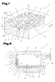
- a mold 1 consisting of an upper tool part 2 and a lower tool part 3 shown.
- Each of the two tool parts 2 and 3 has mold wall parts 4 and 5, which together form a mold cavity 7 delimiting a mold cavity 6.
- the lower tool part 3 can, such as in Fig. 1 and 2 illustrated, at least one partial surface 8 may be provided, on which a view page 9 of a leather layer 10 can be brought to bear.
- a natural leather layer usually consists of the smooth, durable side view 9 and an opposite inner side 11, which is also called meat side.
- the inside 11, is usually very coarse-pored and fibrous, because it was facing the body of the animal.
- different holding devices 12 can be provided.
- the leather layer 10 it is possible for the leather layer 10 to be inserted to be provided with an adhesive which allows it to adhere to the partial surface 8 of the mold wall 7.
- any other technology known from the prior art for the positioned holding and fixing of the leather layer 10 to be inserted into the mold cavity 6 can also be used.
- the partial surface 8, on which at least in part the leather layer 10 is applied for injection molding with a plastic 17 from an injection molding device 18, is formed with a structured surface, which is adapted to the leather structure of a natural leather.
- a surface structure is formed in the existing example of steel mold wall 7 and in the lower or upper tool part 2, 3.
- a structured surface - shown schematically - is provided.
- This structured surface consists of raised areas 19 and adjacent recessed areas 20 and is modeled on the structure of a natural leather.
- These raised and recessed areas 19, 20 can be produced by various methods and methods.
- insert parts 21 makes it possible to produce different surface designs or structured surfaces with the same mold 1 in the current production or to better maintain the structured surface.
- the structured surface can now be produced by various methods and processes. It is thus possible for the raised regions 19 to be deposited on surfaces by means of one or more layers by means of PVD (Physical Vapor Deposition) or CVD (Chemical Vapor Deposition) methods. Both methods have in common that the coating materials are deposited from the vapor phase on the workpiece surface.
- PVD Physical Vapor Deposition
- CVD Chemical Vapor Deposition
- Both methods have in common that the coating materials are deposited from the vapor phase on the workpiece surface.
- the coating material is converted into the vapor phase in a high vacuum via the physical processes of evaporation or cathode sputtering and then deposited on the surface to be coated.
- the CVD process is the separation of solids from the gas phase, whereby the gas phase is generated chemically in contrast to the PVD process.
- the material application is formed, for example, by nickel or nickel alloys.
- the raised areas 19 formed by nickel or nickel alloys in the partial surface 8 have a very high hardness and thus also a long service life for the impressions in the leather layer 10 caused by the injection pressure.
- the raised areas 19 in the sub-area 8 by depositing nickel or nickel alloys from the vapor phase by the aforementioned PVD or CVD processes.
- the insert part 21, on which a partial surface 8 or a part of a partial surface 8 is arranged consists entirely of nickel or a nickel alloy.
- the sub-area 8 instead of producing the raised areas 19, it is also possible in the sub-area 8 to remove the recessed areas 20 adjacent to the recessed areas 19 by appropriate removal methods, such as spark erosion or particle or laser radiation or electro-chemical methods, so that the raised Areas 19, which are intended to represent the depressions in the leather structure and to be embossed in the manufacture of the molding 22 in the surface of the view page 9 of the leather layer 10 to form. Since the volume of the areas recessed in the leather structure is usually substantially lower than that of the raised areas in the side view 9 of natural leather, methods for applying the raised areas 19 are advantageously used in such natural leather structures.
- leather layers 10 of natural leather are commonly used. While the natural surface structure is now lost due to the high temperatures and the high injection pressure in the previously known methods for reinforcing leather layers 10 by injection molding with plastic material 17, since the surface is flattened on the highly polished mold surface of the mold wall 7 is characterized by the arrangement of the structured Surface at least in those sub-areas 8, in which a leather layer 10 is inserted, ensures that even after the back molding with the plastic material 17 on the side 9 a leather-like surface structure is retained or this is permanently and permanently embossed or molded into the surface of the view page 9.
- An advantage of the solution according to the invention is, for example, that now any type of leather, for example, leathers, which usually have only a very weak and delicately pronounced or no structuring of their surface; can be reshaped with a structured surface required for the consumer to represent the high quality of the view page 9.
- This leather materials which are sometimes more durable than those that have an extremely strong and easily recognizable grain, for the production of high quality moldings 22 can be used.
- This barrier layer 23 has the task, the penetration of the plastic material 17, which during the injection process, which is introduced with the injection molding device 18 via the injection port 24 into the mold cavity 6, in the most open-pored inner side 11 and meat side of the leather layer 10, especially then, if it is natural leather, to prevent.
- This is simultaneously prevented that the introduced plastic 17 reinforces and stiffens the leather layer 10 and a high elasticity of the leather layer 10 corresponding to the original spatial deformation behavior of a natural leather layer can be obtained even after the production of the corresponding molded part 22.
- This is particularly advantageous if thin-walled moldings 22, which must be very elastic, as for example in watch straps, belts or the like, are used.
- plastic layer 26 For the plastic layer 26 to be connected to the leather layer 10 or the barrier layer 23, a wide variety of materials can be used. Thus, they can be designed, especially with regard to their strength and elasticity or temperature properties, to the particular application within the framework of the expertise of a person skilled in the art.
- the plastic layer 26 is introduced between two leather layers 10, wherein the leather layers 10 can be positioned and held on opposite faces 8 in the mold cavity 6. It is also possible, inter alia, that in the plastic layer 26 to be produced during the back-spraying of the leather layer 10 or the barrier layer 23 corresponding receptacles, holding parts and fixing elements and snap devices are manufactured to the molding 22 on holding or supporting structures in the desired manner and to attach way.
- the plastic layer 26 is formed by a plurality of superimposed layers of similar or different, for example, differently colored or provided with different physical properties plastic materials 17; Furthermore, such different plastic layers 26 can also be arranged next to each other over the entire height of the molded part 22 adjacent to each other.
- the procedure is such that the portions or partial surfaces 8 for supporting the leather layers 10 forming partial surfaces 8 of the mold wall 7 or these surface portions 8 forming surface parts on the insert parts 21 raised areas by the deposition of nickel or nickel alloys be prepared from the vapor phase.
- This application of nickel or nickel alloys can be carried out in one or more successive steps and allows the production of self-extending and different high raised areas 19. Above all, this is a transfer of data from an electronic component measurement of the surface course of natural leather directly for the production of correspondingly required raised areas 19 for forming the surface embossing of the leather layers 10 possible.
- a leather layer 10 is placed with its view side 9 on the designated mold wall 7 or partial surface 8 of this mold wall 7.
- the holding device 12 for example a partially adhering adhesive layer or suction openings 13 of a vacuum system
- the leather layer 10 can be kept positioned on this mold wall 7 or partial surface 8.
- the mold 1 is closed by placing the lower and upper mold parts 2 and 3 together and forms a mold cavity 6 closed towards the outside.
- On the side facing away from the view side 9 of the leather layer 10 side of this leather layer 10 and on this applied barrier layer 23 is then introduced through the injection port 24 of the plastic 17 at high temperature and high pressure by means of the injection molding device 18.
- the leather layer 10 is pressed with its view side 9 against the structured surface of the partial surface 8.
- the leather layer 10 is pressed so strongly against the surface of the partial surface 8 with its structured surface shape that the raised regions 19 press into the side 9 of the leather layer 10 or emboss this side 9 that this takes over the structured surface of the partial surface 8.
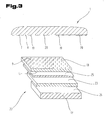
- Fig. 3 is a part of the mold 1 and a possible layer structure of the molding 22 is shown greatly simplified schematically. The individual layers or layers forming the molded part 22 are shown in a separate position in the manner of an exploded view.
- the molded part 22 comprises the leather layer 10 with its view side 9 and the inner side 11 facing away therefrom.
- the barrier layer 23 is assigned to the inner side 11 of the leather layer 10 facing away from the view side 9.
- one or more adhesive layers 25 can be provided to improve the adhesive properties and the connection between the two layers.
- Such a layer can also additionally be arranged on the surface or side of the barrier layer 23 facing the plastic layer 26.
- This semi-finished product or intermediate product can be prepared before the actual production of the molded part 22 by the barrier layer 23 is optionally attached to the inner side 11 of the leather layer 10 with the interposition of the adhesive layer 25.
- this application of the barrier layer 23 can also be effected by a lamination process or other connection processes known from the prior art.
- This prepared layer structure of the semi-finished product can be produced over a large area and assembled before being placed in the mold 1 by a corresponding cutting process for the production of the molding 22.
- the inventive method is based on another mold 1, as shown in Fig. 4 is shown, in turn, for the same parts the same reference numerals or component names as in the preceding Fig. 1 to 3 be used. In order to avoid unnecessary repetition, the detailed description in the previous ones will be used Fig. 1 to 3 referred or referred.
- the mold 1 includes the tool parts 2, 3. Mold wall parts 4 and 5 of the tool parts 2 and 3 together form the mold cavity 6 bounding mold wall 7. On a part surface 8 in one of the tool parts, in the present case in the lower mold part 3, for example, one a surface structure of a natural leather complementary surface structure may be formed, on which a view page 9 of a leather layer 10 can be brought into abutment.
- This view page 9 is usually smooth and durable, while the opposite inner side 11, the meat side, usually very coarse-pored and fibrous.
- a holding device 12 is usually provided which can be formed, for example, by suction openings 13, which are connected via a channel 14 to a vacuum generator, or an adhesive layer. Due to the negative pressure, the leather layer 10 can be held and positioned in an exact position in the mold cavity 6.
- an intermediate layer 27 and a barrier layer 28 is further arranged on the leather layer 10.
- the intermediate layer 27 is at least partially permanently deformable in the direction perpendicular to the inside 11 of the leather layer 10 and made of plastic.
- a barrier layer 28 is formed or arranged as a separate layer on this intermediate layer 27.
- the leather layer 10 placed on the mold wall 7 or a partial surface 8 of the mold wall 7 is back-injected with a plastic 29 for producing a plastic layer 30.
- the structured surface in sub-area 8 consists of raised areas 31 and these adjacent recessed areas 32, and the structure of raised and recessed areas 31, 32 is complementary to the desired surface texture of a natural leather of which this structure is commonly adopted or accepted.
- the raised and recessed areas 31, 32 can be made by various methods and methods.
- the plastic 29 is then applied to the barrier layer 28 to form a molded part 33.
- the plastic 29 is injected via an injection opening of a schematically indicated injection molding device and molded onto the barrier layer 28.
- the intermediate layer 27 and the barrier layer 28 during the introduction of the plastic 29 into the mold cavity 6 between these individual layers adhesive layers 34, for example, by adhesive and / or temperature activatable adhesive films 35, 36th may be arranged.
- the surface structures arranged in the mold wall part 4, 5 or in a part surface 8 of the latter are in the surface of the view side 9 the leather layer 10 Imprinted or leatherette layer or the leather layer 10 is spatially deformed in total, wherein the leather layer 10 - as it is better Fig. 8 can be seen - partially, in the raised areas 31 of the surface 8 is pressed into the intermediate layer 27. At the same time, the elastically deformable intermediate layer 27 is compacted.
- the molding 33 has a thickness 37 during the injection process or as long as it is arranged in the mold cavity 6 and the tool parts 2, 3 are shot.
- the thickness or thickness of this intermediate layer 27 remains unchanged during the injection process of the plastic 29 or is the thickness or thickness of this intermediate layer 27 through plastic deformation of the material of this intermediate layer 27 is reduced.
- this thickness 37 is maintained even after removal of the molded part 33.
- the intermediate layer 27 made of a material which is elastically recoverable - eg by gas formation in the intermediate layer 27 during the pressure and temperature stress during injection of the plastic 29 - so after removal of the molding 33 from the mold cavity 6 the Resetting the intermediate layer 27 to a greater or lesser extent and a thickness 38 of the molding 33 after removal from the mold cavity 6 be greater than the thickness 37 during manufacture or before and after the injection of the plastic 29 and before the removal of the molding 33 from the mold 1.
- This arrangement of the intermediate layer 27 now makes it possible to adapt the elasticity properties of the leather layer 10 or of the entire molded part 33 to a very wide variety of applications and properties.
- the intermediate layer 27 by appropriate design of the intermediate layer 27, a damping in case of impact of objects or persons on such moldings 33 can be preset accordingly. But it is also possible to change the expansion and elongation properties of the leather layer 10 and the entire molded part 33 at different temperatures or loads. In addition, corresponding other physical properties can be achieved by the thickness of this intermediate layer and its physical and chemical properties, such as a sound insulation.
- the intermediate layer 27 is produced from a material which has elastically recoverable properties, then it is also possible for the surface of the leather layer 10 to elastically return to its starting position during a pressure load on the molded part 1 in individual regions or over the entire surface , so that a high quality and a long period of use can be achieved even with corresponding mechanical stresses such moldings 33.
- elastically deformable plastic foams such as polyurethane (PUR), polyethylene (PE), polyimide (PI), polyether, silicone, silicone elastomer, memory foam, open-cell polyurethane foam, open-pore latex foam and the like, are preferably used or combined with one another as desired wherein the memory foam is an ester-based polyurethane foam having pronounced viscoelastic behavior.
- PUR polyurethane
- PE polyethylene
- PI polyimide
- polyether silicone
- silicone elastomer silicone elastomer
- memory foam open-cell polyurethane foam having pronounced viscoelastic behavior.
- the depth of impression of this intermediate layer 27 and in conjunction therewith its thickness or thickness is such that the permanent deformation of the plastic material or the depth of impression by the injection pressure during injection of the plastic 29 is lower than the thickness of the intermediate layer 27 when placed in the mold 1.
- the formation of the barrier layer 28 simultaneously prevents the plasticized plastic 29 from penetrating into the intermediate layer 27 or into the inside of the leather layer 10 during the injection into the mold cavity 6.
- the elasticity properties of the intermediate layer 27 and the leather layer 10 also remain during the curing of the plastic 29, which usually has a higher strength and lower dimensional deformability than the leather layer 10 and the intermediate layer 27.
- Fig. 6 the construction of a molding 33 is shown. It can be seen that the leather layer 10 is provided on its view side 9 with a surface structure, ie with raised areas 41 and with recessed areas 42, this surface structure of the surface structure of a desired type of leather as possible corresponds.
- This leather layer 10 is connected to the intermediate layer 27 via an adhesive layer 34 and to the barrier layer 28 via a further adhesive layer 34.
- the plastic 29 is sprayed and formed by the injection process and the heating and given by the plastic properties of the barrier layer 28.
- the leather layer 10 due to the relative mobilities, in Depending on the residual elasticity of the adhesive layer 34 with respect to the intermediate layer 27 and the barrier layer 28 or the plastic 29 of the plastic layer 30 deform in any direction in the plane of the leather layer 10 or move and move, so that even with strong sudden stresses with more pointed objects Bursting or tearing of the leather layer 10, especially with thinner leather layers 10, can be prevented.
- This is a highly durable surface created in leather design.
- By appropriate training of the plastic layer 30 can be created at the same time for attachment of the molding 33, for example by molding and molding of fasteners, recordings or snap devices.
- the intermediate layer 27 can also be formed on an inner side 11 of the leather layer 10 without the interposition of an adhesive layer 34. It is possible to apply the plastic foam for the production of the intermediate layer 27 directly liquid to the leather layer 10, for example in a continuous flow process. In the case of the open-pored plastic foam, from which the intermediate layer 27 can be expediently formed, it can be effected by cooling on the side facing away from the leather layer 10 that the pores close and a closed-pore surface is formed on the intermediate layer 27, which immediately - as schematically indicated - forms a molded barrier layer 28.
- prefabricated intermediate layers 27 which are prepared on one side with an adhesive film 34 for bonding to the inside 11 of the leather layer 10 and whose pores on the opposite side are closed by pressure and / or temperature influence; so that they form the barrier layer 28.
- the plasticized plastic 29 of the plastic layer 30 can then be applied directly to this barrier layer 28.
- inventively formed molding 33 a leather layer 10 are used with a small thickness 39.
- a spatial deformation of the entire leather layer With appropriate deformation by the structured surface, with which a mold wall part 4, 5 or a partial surface 8 of the mold wall 7 is provided, there is a spatial deformation of the entire leather layer.
- the intermediate layer 27 is designed such that it allows a permanent plastic deformation in adaptation of the deformation of the leather layer 10 and in this position "solidified” or the position is "frozen".
- a first intermediate layer 27 may be formed to accommodate the deformation of the leather layer 10
- a second intermediate layer 40 may be provided with corresponding elastic recovery properties, so that after deformation of the leather layer 10 and the pressing of the plastic 29th the plastic layer 30, the elastic properties or deformation possibilities of the leather layer 10 are maintained.
- the barrier layer 23, 28 may be formed by a high resistance to the influences of weather, UV radiation or mechanical stress material, such as PVC, PMMA, PP, PE, PETP or the like. These different materials may additionally be mixed with various stabilizers or the like, for example to prevent the passage of UV or other radiation as possible.
- the barrier layer 23, 28 may also comprise a plurality of layers and be reinforced, for example, from a layer of textile or a grid or mesh or a mat, in particular of metal or any other fibers or threads or a knitted fabric or fleece. But it is also possible to produce the barrier layer 23, 28, for example, by a printed layer of paper. But it can also be formed by any plastics, plastic films or moldings or the like.
- This barrier layer 23, 28 may be connected via the adhesive layer 25, 34 to the leather layer 10 or at least one of the intermediate layers 27, 40, which is to protect the leather layer 10 against excessive pressure, temperature or shear stresses during the application of the plastic layer 26, 30 ,
- the barrier layer 23, 28 may be formed of a polytetrafluoroethylene.
- an additional layer consisting of a bonding agent for full-surface connection of the barrier layer 23, 28 with the plastic layer 26, 30 may be applied to the barrier layer 23, 28 an additional layer consisting of a bonding agent.
- the most diverse materials, but especially plastic films advantageously from the group of the following, by way of example and not fully enumerated materials, such as PVC (hard , soft), PC, PET, PET-P, PS, PA, CA, PP, PE, PMMA, ABS and EAA.
- plastic materials such as PP, POM, ABS, SAN, PMMA, TPU, EAA, PUR, PC are usable.
- leather used in the description and in the claims for the leather layer 10 includes natural leather as well as artificial leather.
- Faux leather is understood to mean a composite of textile fabric with a coating of plastic. These are natural fiber fabrics or synthetic fibers coated with a soft PVC layer. These coatings can be made compact or foamed depending on the application. As a rule, the surfaces are still grained or grained during the production of the plastic layer 26, 30, so that they correspond to a leather structure.
- Examples of applications for artificial leather are bracelets, belts, trim and trim parts in the automotive industry, shoes, bags, balls (e.g., footballs). Modern synthetic leathers are often provided with a polyurethane coating instead of the PVC coating.
- barrier layer 23, 28 for example, films or layers of the aforementioned materials can be used.
Landscapes
- Engineering & Computer Science (AREA)
- Mechanical Engineering (AREA)
- Manufacturing & Machinery (AREA)
- Injection Moulding Of Plastics Or The Like (AREA)
- Moulds For Moulding Plastics Or The Like (AREA)
Priority Applications (1)
| Application Number | Priority Date | Filing Date | Title |
|---|---|---|---|
| EP20070019221 EP2042291B1 (fr) | 2007-09-29 | 2007-09-29 | Procédé de fabrication d'une pièce moulée et pièce moulée |
Applications Claiming Priority (1)
| Application Number | Priority Date | Filing Date | Title |
|---|---|---|---|
| EP20070019221 EP2042291B1 (fr) | 2007-09-29 | 2007-09-29 | Procédé de fabrication d'une pièce moulée et pièce moulée |
Publications (2)
| Publication Number | Publication Date |
|---|---|
| EP2042291A1 true EP2042291A1 (fr) | 2009-04-01 |
| EP2042291B1 EP2042291B1 (fr) | 2014-04-23 |
Family
ID=38988271
Family Applications (1)
| Application Number | Title | Priority Date | Filing Date |
|---|---|---|---|
| EP20070019221 Expired - Fee Related EP2042291B1 (fr) | 2007-09-29 | 2007-09-29 | Procédé de fabrication d'une pièce moulée et pièce moulée |
Country Status (1)
| Country | Link |
|---|---|
| EP (1) | EP2042291B1 (fr) |
Cited By (6)
| Publication number | Priority date | Publication date | Assignee | Title |
|---|---|---|---|---|
| WO2015124660A1 (fr) * | 2014-02-19 | 2015-08-27 | Johnson Controls Interiors Gmbh & Co. Kg | Corps moulés multicouches destinés aux équipements intérieurs de véhicules et procédé de fabrication desdits corps moulé |
| US20190021534A1 (en) * | 2017-07-21 | 2019-01-24 | Xiamen Sheep Anti-Fatigue Mat Co.,Ltd | Anti-fatigue mats and methods for making the same |
| CN111941737A (zh) * | 2020-09-18 | 2020-11-17 | 常熟市汽车饰件股份有限公司 | 表面嵌入玻璃纤维复合片材的注塑产品局部加强注塑方法 |
| EP3838575A1 (fr) | 2019-12-20 | 2021-06-23 | Engelbert Strauss GmbH & Co. KG | Procédé de fabrication d'une semelle ainsi qu'outil d'injection ou de coulée |
| DE102020122779B3 (de) | 2020-09-01 | 2022-03-03 | J. & F. Krüth GmbH | Verfahren zum Herstellen, Bearbeiten, Veränderung und/oder zur Veredelung eines Formwerkzeuges sowie Spritzgusswerkzeug |
| CN114179387A (zh) * | 2021-12-27 | 2022-03-15 | 广州海天塑胶有限公司 | 一种塑料零件模内塑料件皮革包覆工艺 |
Citations (3)
| Publication number | Priority date | Publication date | Assignee | Title |
|---|---|---|---|---|
| US5650115A (en) * | 1992-08-31 | 1997-07-22 | Plastic Mold Technology Incorporated | Method for making molded air bag covers and other articles with integral cover layer of leather |
| DE19926470A1 (de) * | 1999-06-10 | 2000-12-14 | Bayerische Motoren Werke Ag | Verfahren zum Aufbringen einer Sperrschicht auf die Rückseite eines Dekorbezuges |
| DE10119494A1 (de) * | 2001-04-20 | 2002-10-24 | Basf Ag | Formkörper aus Leder und Thermoplast mit verbessertem Soft-Touch |
-
2007
- 2007-09-29 EP EP20070019221 patent/EP2042291B1/fr not_active Expired - Fee Related
Patent Citations (3)
| Publication number | Priority date | Publication date | Assignee | Title |
|---|---|---|---|---|
| US5650115A (en) * | 1992-08-31 | 1997-07-22 | Plastic Mold Technology Incorporated | Method for making molded air bag covers and other articles with integral cover layer of leather |
| DE19926470A1 (de) * | 1999-06-10 | 2000-12-14 | Bayerische Motoren Werke Ag | Verfahren zum Aufbringen einer Sperrschicht auf die Rückseite eines Dekorbezuges |
| DE10119494A1 (de) * | 2001-04-20 | 2002-10-24 | Basf Ag | Formkörper aus Leder und Thermoplast mit verbessertem Soft-Touch |
Cited By (9)
| Publication number | Priority date | Publication date | Assignee | Title |
|---|---|---|---|---|
| WO2015124660A1 (fr) * | 2014-02-19 | 2015-08-27 | Johnson Controls Interiors Gmbh & Co. Kg | Corps moulés multicouches destinés aux équipements intérieurs de véhicules et procédé de fabrication desdits corps moulé |
| US20190021534A1 (en) * | 2017-07-21 | 2019-01-24 | Xiamen Sheep Anti-Fatigue Mat Co.,Ltd | Anti-fatigue mats and methods for making the same |
| US10639831B2 (en) * | 2017-07-21 | 2020-05-05 | Xiamen Sheep Anti-Fatigue Mat Co., Ltd | Anti-fatigue mats and methods for making the same |
| EP3838575A1 (fr) | 2019-12-20 | 2021-06-23 | Engelbert Strauss GmbH & Co. KG | Procédé de fabrication d'une semelle ainsi qu'outil d'injection ou de coulée |
| DE102019135525A1 (de) * | 2019-12-20 | 2021-06-24 | Engelbert Strauss Gmbh & Co Kg | Verfahren zum Herstellen einer Laufsohle sowie Spritz- oder Gießwerkzeug |
| DE102020122779B3 (de) | 2020-09-01 | 2022-03-03 | J. & F. Krüth GmbH | Verfahren zum Herstellen, Bearbeiten, Veränderung und/oder zur Veredelung eines Formwerkzeuges sowie Spritzgusswerkzeug |
| CN111941737A (zh) * | 2020-09-18 | 2020-11-17 | 常熟市汽车饰件股份有限公司 | 表面嵌入玻璃纤维复合片材的注塑产品局部加强注塑方法 |
| CN111941737B (zh) * | 2020-09-18 | 2022-11-15 | 江苏常熟汽饰集团股份有限公司 | 表面嵌入玻璃纤维复合片材的注塑产品局部加强注塑方法 |
| CN114179387A (zh) * | 2021-12-27 | 2022-03-15 | 广州海天塑胶有限公司 | 一种塑料零件模内塑料件皮革包覆工艺 |
Also Published As
| Publication number | Publication date |
|---|---|
| EP2042291B1 (fr) | 2014-04-23 |
Similar Documents
| Publication | Publication Date | Title |
|---|---|---|
| EP2684745B1 (fr) | Pièce d'habillage intérieur et son procédé de fabrication | |
| DE102015209797B3 (de) | Paneel für einen Ball | |
| EP1064135B1 (fr) | Dispositif et procede pour poser dans le moule un materiau decoratif, ainsi que pour border ce dernier d'un materiau de support | |
| DE102011102722A1 (de) | Verfahren und Vorrichtung zum In-Mold-Dekorieren | |
| EP2042291B1 (fr) | Procédé de fabrication d'une pièce moulée et pièce moulée | |
| EP3107706B1 (fr) | Corps moulé multicouche pour équipement d'intérieur de véhicule et procédé pour la fabrication d'un tel corps | |
| WO2009052889A1 (fr) | Procédé et dispositif de fabrication d'une pièce moulée qui présente une ligne de rupture préférentielle pour l'ouverture d'un airbag | |
| DE102015003448A1 (de) | Zierteil, Dekorteil und Verfahren zur Herstellung eines Zierteils | |
| WO2008064915A1 (fr) | Procédé de fabrication d'une pièce composite dotée d'une couche de recouvrement en plusieurs parties et pièce composite | |
| DE102006013857B4 (de) | Verfahren zur Herstellung eines dekorierten Kunststoffformteils mit einer teilweisen Polsterung | |
| WO2011088995A1 (fr) | Procédé de fabrication d'un élément de revêtement intérieur | |
| DE10126703B4 (de) | Verfahren zur Herstellung von Innenraumverkleidungsteilen | |
| DE10218004B3 (de) | Herstellung eines Innenausstattungsteils und Innenausstattungsteil | |
| WO2008101739A2 (fr) | Procédé et moule pour produire un élément grainé | |
| EP1626852B1 (fr) | Element composite et procede de production correspondant | |
| EP2033759A1 (fr) | Procédé de fabrication d'une pièce de formage dotée de différentes zones de décoration | |
| DE102010037022B4 (de) | Vorrichtung und Verfahren zur Herstellung eines Formteils mit dreidimensional strukturierter Oberfläche | |
| DE10338109B4 (de) | Verfahren zur Herstellung eines Verbundbauteils | |
| DE202010008303U1 (de) | Vorrichtung zur Herstellung eines Formteils mit dreidimensional strukturierter Oberfläche | |
| DE10218890B4 (de) | Verfahren zum Herstellen eines flächigen Verbundbauteils | |
| DE102005011474B4 (de) | Verfahren zur Herstellung von Kunststoffformteilen mit Hinterschneidungen unter Verwendung eingelegter Füllstücke | |
| DE202009006239U1 (de) | Vorrichtung zur Herstellung eines Kunststoff-Formteils | |
| DE102018118426A1 (de) | Verfahren und system zur verwendung eines offenen spritzgiessverfahrens mit einem einzelwerkzeug für verkleidungskomponenten | |
| EP1695807B1 (fr) | Procédé pour fabriquer une pièce moulée en mousse comprenant une zone décorative | |
| DE102007056334B4 (de) | Verfahren zum Herstellen einer Instrumententafel und Instrumententafel eines Fahrzeugs |
Legal Events
| Date | Code | Title | Description |
|---|---|---|---|
| PUAI | Public reference made under article 153(3) epc to a published international application that has entered the european phase |
Free format text: ORIGINAL CODE: 0009012 |
|
| AK | Designated contracting states |
Kind code of ref document: A1 Designated state(s): AT BE BG CH CY CZ DE DK EE ES FI FR GB GR HU IE IS IT LI LT LU LV MC MT NL PL PT RO SE SI SK TR |
|
| AX | Request for extension of the european patent |
Extension state: AL BA HR MK RS |
|
| 17P | Request for examination filed |
Effective date: 20090514 |
|
| 17Q | First examination report despatched |
Effective date: 20091112 |
|
| AKX | Designation fees paid |
Designated state(s): DE FR GB IT |
|
| RAP1 | Party data changed (applicant data changed or rights of an application transferred) |
Owner name: HAT SKINLINE GMBH Owner name: BAYERISCHE MOTOREN WERKE AKTIENGESELLSCHAFT |
|
| RAP1 | Party data changed (applicant data changed or rights of an application transferred) |
Owner name: BAYERISCHE MOTOREN WERKE AKTIENGESELLSCHAFT Owner name: HTP SKINLINE GMBH |
|
| RAP1 | Party data changed (applicant data changed or rights of an application transferred) |
Owner name: BAYERISCHE MOTOREN WERKE AKTIENGESELLSCHAFT Owner name: HTP HIGH TECH PLASTICS GMBH |
|
| GRAP | Despatch of communication of intention to grant a patent |
Free format text: ORIGINAL CODE: EPIDOSNIGR1 |
|
| RIC1 | Information provided on ipc code assigned before grant |
Ipc: B29C 33/56 20060101ALI20131028BHEP Ipc: B29C 45/37 20060101AFI20131028BHEP Ipc: B29L 31/30 20060101ALN20131028BHEP Ipc: B29C 45/14 20060101ALI20131028BHEP Ipc: B29K 711/08 20060101ALN20131028BHEP |
|
| INTG | Intention to grant announced |
Effective date: 20131129 |
|
| GRAS | Grant fee paid |
Free format text: ORIGINAL CODE: EPIDOSNIGR3 |
|
| GRAA | (expected) grant |
Free format text: ORIGINAL CODE: 0009210 |
|
| AK | Designated contracting states |
Kind code of ref document: B1 Designated state(s): DE FR GB IT |
|
| REG | Reference to a national code |
Ref country code: GB Ref legal event code: FG4D Free format text: NOT ENGLISH |
|
| REG | Reference to a national code |
Ref country code: DE Ref legal event code: R096 Ref document number: 502007013005 Country of ref document: DE Effective date: 20140528 |
|
| RAP2 | Party data changed (patent owner data changed or rights of a patent transferred) |
Owner name: BAYERISCHE MOTOREN WERKE AKTIENGESELLSCHAFT Owner name: HTP HIGH TECH PLASTICS GMBH |
|
| REG | Reference to a national code |
Ref country code: DE Ref legal event code: R097 Ref document number: 502007013005 Country of ref document: DE |
|
| PLBE | No opposition filed within time limit |
Free format text: ORIGINAL CODE: 0009261 |
|
| STAA | Information on the status of an ep patent application or granted ep patent |
Free format text: STATUS: NO OPPOSITION FILED WITHIN TIME LIMIT |
|
| 26N | No opposition filed |
Effective date: 20150126 |
|
| REG | Reference to a national code |
Ref country code: DE Ref legal event code: R097 Ref document number: 502007013005 Country of ref document: DE Effective date: 20150126 |
|
| REG | Reference to a national code |
Ref country code: FR Ref legal event code: PLFP Year of fee payment: 10 |
|
| REG | Reference to a national code |
Ref country code: FR Ref legal event code: PLFP Year of fee payment: 11 |
|
| REG | Reference to a national code |
Ref country code: FR Ref legal event code: PLFP Year of fee payment: 12 |
|
| PGFP | Annual fee paid to national office [announced via postgrant information from national office to epo] |
Ref country code: FR Payment date: 20190923 Year of fee payment: 13 Ref country code: IT Payment date: 20190920 Year of fee payment: 13 |
|
| PGFP | Annual fee paid to national office [announced via postgrant information from national office to epo] |
Ref country code: GB Payment date: 20190924 Year of fee payment: 13 |
|
| PGFP | Annual fee paid to national office [announced via postgrant information from national office to epo] |
Ref country code: DE Payment date: 20190930 Year of fee payment: 13 |
|
| REG | Reference to a national code |
Ref country code: DE Ref legal event code: R119 Ref document number: 502007013005 Country of ref document: DE |
|
| GBPC | Gb: european patent ceased through non-payment of renewal fee |
Effective date: 20200929 |
|
| PG25 | Lapsed in a contracting state [announced via postgrant information from national office to epo] |
Ref country code: DE Free format text: LAPSE BECAUSE OF NON-PAYMENT OF DUE FEES Effective date: 20210401 Ref country code: FR Free format text: LAPSE BECAUSE OF NON-PAYMENT OF DUE FEES Effective date: 20200930 |
|
| PG25 | Lapsed in a contracting state [announced via postgrant information from national office to epo] |
Ref country code: GB Free format text: LAPSE BECAUSE OF NON-PAYMENT OF DUE FEES Effective date: 20200929 |
|
| PG25 | Lapsed in a contracting state [announced via postgrant information from national office to epo] |
Ref country code: IT Free format text: LAPSE BECAUSE OF NON-PAYMENT OF DUE FEES Effective date: 20200929 |