EP2042291A1 - Method for producing a moulded part - Google Patents
Method for producing a moulded part Download PDFInfo
- Publication number
- EP2042291A1 EP2042291A1 EP07019221A EP07019221A EP2042291A1 EP 2042291 A1 EP2042291 A1 EP 2042291A1 EP 07019221 A EP07019221 A EP 07019221A EP 07019221 A EP07019221 A EP 07019221A EP 2042291 A1 EP2042291 A1 EP 2042291A1
- Authority
- EP
- European Patent Office
- Prior art keywords
- layer
- leather
- plastic
- mold
- molding
- Prior art date
- Legal status (The legal status is an assumption and is not a legal conclusion. Google has not performed a legal analysis and makes no representation as to the accuracy of the status listed.)
- Granted
Links
- 238000004519 manufacturing process Methods 0.000 title claims abstract description 31
- 239000010410 layer Substances 0.000 claims abstract description 413
- 239000010985 leather Substances 0.000 claims abstract description 226
- 229920003023 plastic Polymers 0.000 claims abstract description 157
- 239000004033 plastic Substances 0.000 claims abstract description 157
- 239000000463 material Substances 0.000 claims abstract description 76
- 238000000465 moulding Methods 0.000 claims abstract description 67
- 238000000034 method Methods 0.000 claims abstract description 64
- 239000012790 adhesive layer Substances 0.000 claims abstract description 29
- 230000001070 adhesive effect Effects 0.000 claims abstract description 9
- 239000000853 adhesive Substances 0.000 claims abstract description 8
- 230000004888 barrier function Effects 0.000 claims description 65
- PXHVJJICTQNCMI-UHFFFAOYSA-N Nickel Chemical compound [Ni] PXHVJJICTQNCMI-UHFFFAOYSA-N 0.000 claims description 26
- 239000002313 adhesive film Substances 0.000 claims description 16
- 239000004800 polyvinyl chloride Substances 0.000 claims description 15
- 229920000915 polyvinyl chloride Polymers 0.000 claims description 15
- 229910000990 Ni alloy Inorganic materials 0.000 claims description 13
- 229910052759 nickel Inorganic materials 0.000 claims description 13
- 239000002984 plastic foam Substances 0.000 claims description 12
- 238000000151 deposition Methods 0.000 claims description 8
- 239000004814 polyurethane Substances 0.000 claims description 8
- 230000005855 radiation Effects 0.000 claims description 8
- 229920002635 polyurethane Polymers 0.000 claims description 7
- 239000004676 acrylonitrile butadiene styrene Substances 0.000 claims description 6
- 229920000122 acrylonitrile butadiene styrene Polymers 0.000 claims description 6
- 238000005229 chemical vapour deposition Methods 0.000 claims description 6
- 239000002131 composite material Substances 0.000 claims description 6
- 239000011148 porous material Substances 0.000 claims description 6
- 239000012808 vapor phase Substances 0.000 claims description 6
- 230000008021 deposition Effects 0.000 claims description 5
- 229920006255 plastic film Polymers 0.000 claims description 5
- 239000002985 plastic film Substances 0.000 claims description 5
- 229920005830 Polyurethane Foam Polymers 0.000 claims description 4
- 238000003466 welding Methods 0.000 claims description 4
- 229910000831 Steel Inorganic materials 0.000 claims description 3
- 229920001821 foam rubber Polymers 0.000 claims description 3
- 238000007373 indentation Methods 0.000 claims description 3
- 239000002245 particle Substances 0.000 claims description 3
- 239000011496 polyurethane foam Substances 0.000 claims description 3
- 239000010959 steel Substances 0.000 claims description 3
- 238000002844 melting Methods 0.000 claims description 2
- 230000008018 melting Effects 0.000 claims description 2
- 238000007493 shaping process Methods 0.000 claims 2
- 239000006181 electrochemical material Substances 0.000 claims 1
- 238000003825 pressing Methods 0.000 abstract description 2
- 239000011888 foil Substances 0.000 abstract 1
- 238000002347 injection Methods 0.000 description 23
- 239000007924 injection Substances 0.000 description 23
- 230000008569 process Effects 0.000 description 14
- 238000001746 injection moulding Methods 0.000 description 12
- 239000000243 solution Substances 0.000 description 9
- 230000008901 benefit Effects 0.000 description 7
- 238000013016 damping Methods 0.000 description 6
- 239000002649 leather substitute Substances 0.000 description 6
- 238000005240 physical vapour deposition Methods 0.000 description 6
- 238000000576 coating method Methods 0.000 description 5
- 230000035515 penetration Effects 0.000 description 5
- 239000004698 Polyethylene Substances 0.000 description 4
- 239000011248 coating agent Substances 0.000 description 4
- 238000013461 design Methods 0.000 description 4
- 238000004049 embossing Methods 0.000 description 4
- 235000013372 meat Nutrition 0.000 description 4
- 229920000573 polyethylene Polymers 0.000 description 4
- 239000004743 Polypropylene Substances 0.000 description 3
- 230000006978 adaptation Effects 0.000 description 3
- 230000006399 behavior Effects 0.000 description 3
- 239000004744 fabric Substances 0.000 description 3
- -1 for example Substances 0.000 description 3
- 238000010438 heat treatment Methods 0.000 description 3
- 238000009413 insulation Methods 0.000 description 3
- 239000007788 liquid Substances 0.000 description 3
- 230000000704 physical effect Effects 0.000 description 3
- 229920003229 poly(methyl methacrylate) Polymers 0.000 description 3
- 239000005020 polyethylene terephthalate Substances 0.000 description 3
- 229920000139 polyethylene terephthalate Polymers 0.000 description 3
- 239000004926 polymethyl methacrylate Substances 0.000 description 3
- 239000004716 Ethylene/acrylic acid copolymer Substances 0.000 description 2
- 229920000079 Memory foam Polymers 0.000 description 2
- 239000004642 Polyimide Substances 0.000 description 2
- 230000015572 biosynthetic process Effects 0.000 description 2
- 230000008859 change Effects 0.000 description 2
- 230000000295 complement effect Effects 0.000 description 2
- 238000001816 cooling Methods 0.000 description 2
- 238000006073 displacement reaction Methods 0.000 description 2
- 230000000694 effects Effects 0.000 description 2
- 229920006226 ethylene-acrylic acid Polymers 0.000 description 2
- 239000000835 fiber Substances 0.000 description 2
- 238000000227 grinding Methods 0.000 description 2
- 239000011229 interlayer Substances 0.000 description 2
- 239000008210 memory foam Substances 0.000 description 2
- 239000012071 phase Substances 0.000 description 2
- 239000012994 photoredox catalyst Substances 0.000 description 2
- 239000004417 polycarbonate Substances 0.000 description 2
- 229920001721 polyimide Polymers 0.000 description 2
- 230000008092 positive effect Effects 0.000 description 2
- 239000000047 product Substances 0.000 description 2
- 238000011084 recovery Methods 0.000 description 2
- 239000011265 semifinished product Substances 0.000 description 2
- 229920002379 silicone rubber Polymers 0.000 description 2
- 239000007787 solid Substances 0.000 description 2
- 239000004753 textile Substances 0.000 description 2
- 239000004721 Polyphenylene oxide Substances 0.000 description 1
- 239000004793 Polystyrene Substances 0.000 description 1
- 239000004433 Thermoplastic polyurethane Substances 0.000 description 1
- 230000009471 action Effects 0.000 description 1
- 230000033228 biological regulation Effects 0.000 description 1
- 239000007767 bonding agent Substances 0.000 description 1
- 230000009172 bursting Effects 0.000 description 1
- 238000010276 construction Methods 0.000 description 1
- 238000005112 continuous flow technique Methods 0.000 description 1
- 238000005520 cutting process Methods 0.000 description 1
- 238000009760 electrical discharge machining Methods 0.000 description 1
- 238000002848 electrochemical method Methods 0.000 description 1
- 238000005516 engineering process Methods 0.000 description 1
- 150000002148 esters Chemical class 0.000 description 1
- 230000008020 evaporation Effects 0.000 description 1
- 238000001704 evaporation Methods 0.000 description 1
- 239000002360 explosive Substances 0.000 description 1
- 238000011049 filling Methods 0.000 description 1
- 230000009969 flowable effect Effects 0.000 description 1
- 239000006260 foam Substances 0.000 description 1
- 230000003993 interaction Effects 0.000 description 1
- 239000013067 intermediate product Substances 0.000 description 1
- 238000005304 joining Methods 0.000 description 1
- 238000003475 lamination Methods 0.000 description 1
- 238000011068 loading method Methods 0.000 description 1
- 230000014759 maintenance of location Effects 0.000 description 1
- 238000005259 measurement Methods 0.000 description 1
- 239000002184 metal Substances 0.000 description 1
- 229910052751 metal Inorganic materials 0.000 description 1
- 230000037230 mobility Effects 0.000 description 1
- 230000000149 penetrating effect Effects 0.000 description 1
- WXZMFSXDPGVJKK-UHFFFAOYSA-N pentaerythritol Chemical compound OCC(CO)(CO)CO WXZMFSXDPGVJKK-UHFFFAOYSA-N 0.000 description 1
- 230000002093 peripheral effect Effects 0.000 description 1
- 229920000570 polyether Polymers 0.000 description 1
- 229920000642 polymer Polymers 0.000 description 1
- 229920006324 polyoxymethylene Polymers 0.000 description 1
- 229920001296 polysiloxane Polymers 0.000 description 1
- 229920001343 polytetrafluoroethylene Polymers 0.000 description 1
- 239000004810 polytetrafluoroethylene Substances 0.000 description 1
- 239000011527 polyurethane coating Substances 0.000 description 1
- 238000002360 preparation method Methods 0.000 description 1
- 230000002787 reinforcement Effects 0.000 description 1
- 230000003014 reinforcing effect Effects 0.000 description 1
- 230000000717 retained effect Effects 0.000 description 1
- 238000000926 separation method Methods 0.000 description 1
- 239000004945 silicone rubber Substances 0.000 description 1
- 238000005507 spraying Methods 0.000 description 1
- 238000004544 sputter deposition Methods 0.000 description 1
- 230000006641 stabilisation Effects 0.000 description 1
- 238000011105 stabilization Methods 0.000 description 1
- 239000003381 stabilizer Substances 0.000 description 1
- 229920000638 styrene acrylonitrile Polymers 0.000 description 1
- 239000011145 styrene acrylonitrile resin Substances 0.000 description 1
- 239000000126 substance Substances 0.000 description 1
- 229920002994 synthetic fiber Polymers 0.000 description 1
- 239000012209 synthetic fiber Substances 0.000 description 1
- 229920002803 thermoplastic polyurethane Polymers 0.000 description 1
- 238000012549 training Methods 0.000 description 1
- 238000012546 transfer Methods 0.000 description 1
- 238000013022 venting Methods 0.000 description 1
- 230000000007 visual effect Effects 0.000 description 1
Images


Classifications
-
- B—PERFORMING OPERATIONS; TRANSPORTING
- B29—WORKING OF PLASTICS; WORKING OF SUBSTANCES IN A PLASTIC STATE IN GENERAL
- B29C—SHAPING OR JOINING OF PLASTICS; SHAPING OF MATERIAL IN A PLASTIC STATE, NOT OTHERWISE PROVIDED FOR; AFTER-TREATMENT OF THE SHAPED PRODUCTS, e.g. REPAIRING
- B29C45/00—Injection moulding, i.e. forcing the required volume of moulding material through a nozzle into a closed mould; Apparatus therefor
- B29C45/17—Component parts, details or accessories; Auxiliary operations
- B29C45/26—Moulds
- B29C45/37—Mould cavity walls, i.e. the inner surface forming the mould cavity, e.g. linings
- B29C45/372—Mould cavity walls, i.e. the inner surface forming the mould cavity, e.g. linings provided with means for marking or patterning, e.g. numbering articles
-
- B—PERFORMING OPERATIONS; TRANSPORTING
- B29—WORKING OF PLASTICS; WORKING OF SUBSTANCES IN A PLASTIC STATE IN GENERAL
- B29C—SHAPING OR JOINING OF PLASTICS; SHAPING OF MATERIAL IN A PLASTIC STATE, NOT OTHERWISE PROVIDED FOR; AFTER-TREATMENT OF THE SHAPED PRODUCTS, e.g. REPAIRING
- B29C33/00—Moulds or cores; Details thereof or accessories therefor
- B29C33/56—Coatings, e.g. enameled or galvanised; Releasing, lubricating or separating agents
-
- B—PERFORMING OPERATIONS; TRANSPORTING
- B29—WORKING OF PLASTICS; WORKING OF SUBSTANCES IN A PLASTIC STATE IN GENERAL
- B29C—SHAPING OR JOINING OF PLASTICS; SHAPING OF MATERIAL IN A PLASTIC STATE, NOT OTHERWISE PROVIDED FOR; AFTER-TREATMENT OF THE SHAPED PRODUCTS, e.g. REPAIRING
- B29C45/00—Injection moulding, i.e. forcing the required volume of moulding material through a nozzle into a closed mould; Apparatus therefor
- B29C45/14—Injection moulding, i.e. forcing the required volume of moulding material through a nozzle into a closed mould; Apparatus therefor incorporating preformed parts or layers, e.g. injection moulding around inserts or for coating articles
- B29C45/1418—Injection moulding, i.e. forcing the required volume of moulding material through a nozzle into a closed mould; Apparatus therefor incorporating preformed parts or layers, e.g. injection moulding around inserts or for coating articles the inserts being deformed or preformed, e.g. by the injection pressure
-
- B—PERFORMING OPERATIONS; TRANSPORTING
- B29—WORKING OF PLASTICS; WORKING OF SUBSTANCES IN A PLASTIC STATE IN GENERAL
- B29C—SHAPING OR JOINING OF PLASTICS; SHAPING OF MATERIAL IN A PLASTIC STATE, NOT OTHERWISE PROVIDED FOR; AFTER-TREATMENT OF THE SHAPED PRODUCTS, e.g. REPAIRING
- B29C45/00—Injection moulding, i.e. forcing the required volume of moulding material through a nozzle into a closed mould; Apparatus therefor
- B29C45/14—Injection moulding, i.e. forcing the required volume of moulding material through a nozzle into a closed mould; Apparatus therefor incorporating preformed parts or layers, e.g. injection moulding around inserts or for coating articles
- B29C45/14065—Positioning or centering articles in the mould
- B29C2045/14155—Positioning or centering articles in the mould using vacuum or suction
-
- B—PERFORMING OPERATIONS; TRANSPORTING
- B29—WORKING OF PLASTICS; WORKING OF SUBSTANCES IN A PLASTIC STATE IN GENERAL
- B29C—SHAPING OR JOINING OF PLASTICS; SHAPING OF MATERIAL IN A PLASTIC STATE, NOT OTHERWISE PROVIDED FOR; AFTER-TREATMENT OF THE SHAPED PRODUCTS, e.g. REPAIRING
- B29C33/00—Moulds or cores; Details thereof or accessories therefor
- B29C33/38—Moulds or cores; Details thereof or accessories therefor characterised by the material or the manufacturing process
- B29C33/3814—Porous moulds
-
- B—PERFORMING OPERATIONS; TRANSPORTING
- B29—WORKING OF PLASTICS; WORKING OF SUBSTANCES IN A PLASTIC STATE IN GENERAL
- B29C—SHAPING OR JOINING OF PLASTICS; SHAPING OF MATERIAL IN A PLASTIC STATE, NOT OTHERWISE PROVIDED FOR; AFTER-TREATMENT OF THE SHAPED PRODUCTS, e.g. REPAIRING
- B29C45/00—Injection moulding, i.e. forcing the required volume of moulding material through a nozzle into a closed mould; Apparatus therefor
- B29C45/14—Injection moulding, i.e. forcing the required volume of moulding material through a nozzle into a closed mould; Apparatus therefor incorporating preformed parts or layers, e.g. injection moulding around inserts or for coating articles
- B29C45/14065—Positioning or centering articles in the mould
-
- B—PERFORMING OPERATIONS; TRANSPORTING
- B29—WORKING OF PLASTICS; WORKING OF SUBSTANCES IN A PLASTIC STATE IN GENERAL
- B29C—SHAPING OR JOINING OF PLASTICS; SHAPING OF MATERIAL IN A PLASTIC STATE, NOT OTHERWISE PROVIDED FOR; AFTER-TREATMENT OF THE SHAPED PRODUCTS, e.g. REPAIRING
- B29C45/00—Injection moulding, i.e. forcing the required volume of moulding material through a nozzle into a closed mould; Apparatus therefor
- B29C45/17—Component parts, details or accessories; Auxiliary operations
- B29C45/26—Moulds
- B29C45/2673—Moulds with exchangeable mould parts, e.g. cassette moulds
-
- B—PERFORMING OPERATIONS; TRANSPORTING
- B29—WORKING OF PLASTICS; WORKING OF SUBSTANCES IN A PLASTIC STATE IN GENERAL
- B29K—INDEXING SCHEME ASSOCIATED WITH SUBCLASSES B29B, B29C OR B29D, RELATING TO MOULDING MATERIALS OR TO MATERIALS FOR MOULDS, REINFORCEMENTS, FILLERS OR PREFORMED PARTS, e.g. INSERTS
- B29K2711/00—Use of natural products or their composites, not provided for in groups B29K2601/00 - B29K2709/00, for preformed parts, e.g. for inserts
- B29K2711/08—Leather
-
- B—PERFORMING OPERATIONS; TRANSPORTING
- B29—WORKING OF PLASTICS; WORKING OF SUBSTANCES IN A PLASTIC STATE IN GENERAL
- B29K—INDEXING SCHEME ASSOCIATED WITH SUBCLASSES B29B, B29C OR B29D, RELATING TO MOULDING MATERIALS OR TO MATERIALS FOR MOULDS, REINFORCEMENTS, FILLERS OR PREFORMED PARTS, e.g. INSERTS
- B29K2715/00—Condition, form or state of preformed parts, e.g. inserts
- B29K2715/003—Cellular or porous
-
- B—PERFORMING OPERATIONS; TRANSPORTING
- B29—WORKING OF PLASTICS; WORKING OF SUBSTANCES IN A PLASTIC STATE IN GENERAL
- B29K—INDEXING SCHEME ASSOCIATED WITH SUBCLASSES B29B, B29C OR B29D, RELATING TO MOULDING MATERIALS OR TO MATERIALS FOR MOULDS, REINFORCEMENTS, FILLERS OR PREFORMED PARTS, e.g. INSERTS
- B29K2995/00—Properties of moulding materials, reinforcements, fillers, preformed parts or moulds
- B29K2995/0037—Other properties
- B29K2995/0065—Permeability to gases
- B29K2995/0067—Permeability to gases non-permeable
-
- B—PERFORMING OPERATIONS; TRANSPORTING
- B29—WORKING OF PLASTICS; WORKING OF SUBSTANCES IN A PLASTIC STATE IN GENERAL
- B29L—INDEXING SCHEME ASSOCIATED WITH SUBCLASS B29C, RELATING TO PARTICULAR ARTICLES
- B29L2031/00—Other particular articles
- B29L2031/30—Vehicles, e.g. ships or aircraft, or body parts thereof
- B29L2031/3005—Body finishings
Landscapes
- Engineering & Computer Science (AREA)
- Mechanical Engineering (AREA)
- Manufacturing & Machinery (AREA)
- Injection Moulding Of Plastics Or The Like (AREA)
- Moulds For Moulding Plastics Or The Like (AREA)
Abstract
Description
Die Erfindung betrifft ein Verfahren zur Herstellung eines Formteils, bei dem eine Lederschicht mit ihrer Ansichtsseite auf eine Formwand bzw. zumindest eine Teilfläche einer Formwand eines Formwerkzeuges aufgelegt und positioniert gehalten wird, wobei ein Kunststoffmaterial zur Bildung einer Kunststoffschicht auf der Innenseite der Lederschicht unter Druck in einen Formhohlraum des Formwerkzeugs eingebracht wird. Weiterhin umfasst die Erfindung ein Formteil, ein Formwerkzeug zur Herstellung eines solchen Formteils sowie ein Verfahren zum Herstellen eines Formwerkzeuges.The invention relates to a method for producing a molded part, in which a leather layer is placed with its view side on a mold wall or at least a partial surface of a mold wall of a mold and positioned, wherein a plastic material for forming a plastic layer on the inside of the leather layer under pressure a mold cavity of the mold is introduced. Furthermore, the invention comprises a molding, a molding tool for producing such a molding and a method for producing a molding tool.
Für die Herstellung von beispielsweise bandförmigen Formteilen wie Uhrarmbändern oder Gürteln sind verschiedene Maßnahmen bekannt, um dem Produkt das Aussehen und die Flexibilität von Leder zu geben.For the production of, for example, band-shaped moldings such as watch straps or belts, various measures are known to give the product the appearance and the flexibility of leather.
In der Patentschrift
Ein derart hergestelltes Kunstleder erreicht jedoch weder optisch noch in der Haptik die Eigenschaften von echtem Leder. Es wurde daher schon verschiedentlich vorgeschlagen, mindestens eine Schicht aus Leder mit mindestens einer Schicht aus Kunststoff zu verbinden. Damit wird bezweckt, die positiven Eigenschaften des Leders wie Aussehen, Flexibilität und Geschmeidigkeit mit den positiven Eigenschaften von Kunststoff wie Festigkeit und Feuchtigkeitsbeständigkeit zu kombinieren.However, an artificial leather produced in this way does not achieve the properties of genuine leather either visually or in terms of its feel. It has therefore been variously proposed to connect at least one layer of leather with at least one layer of plastic. The aim is to combine the positive properties of leather such as appearance, flexibility and smoothness with the positive properties of plastic such as strength and moisture resistance.
Aus der Patentschrift
Gemäß der Patentschrift
Die Patentschrift
Das Verbinden von Leder und Kunststoff durch Einspritzen des Kunststoffes in eine Form erscheint einfach und kostengünstig, hat aber den Nachteil, dass so hergestellte Formteile dazu neigen, die Optik und Haptik echten Leders zu verlieren, insbesondere weil das Leder an der Formwand flach gedrückt wird und dadurch seine natürliche Narbung der Oberfläche verliert.The joining of leather and plastic by injecting the plastic into a mold appears simple and inexpensive, but has the disadvantage that moldings produced in this way tend to lose the look and feel of genuine leather, especially because the leather is pressed flat against the mold wall and thereby losing its natural grain of the surface.
Ausgehend von diesem Stand der Technik liegt der Erfindung die Aufgabe zu Grunde, ein Verfahren zur Herstellung eines Formteils mit mindestens einer aus Leder bestehenden Schicht anzugeben, wobei das Formteil eine durch Leder gebildete Ansichtsseite aufweist, die in ihrer Oberflächenstruktur und ihrer Haptik einer strukturieren Naturlederoberfläche möglichst entspricht, bei welchem auch dann, wenn die Lederteile mit Kunststoff hinterspritzt werden oder sind, die Lederteile ihre ursprünglichen Eigenschaften und insbesondere ihre Optik und Haptik beibehalten. Darüber hinaus liegt eine weitere, vorteilhafte Aufgabe darin, ein Formwerkzeug zur Herstellung von Formteilen mit mindestens einer aus Leder bestehenden Schicht vorzuschlagen, bei dem verhindert wird, dass die mit Kunststoff hinterspritzte Lederschicht durch den Spritzdruck flach gepresst wird. Eine bevorzugte weitere Aufgabe liegt darin, ein Verfahren zu schaffen, mit dem das Formwerkzeug einfach und kostengünstig für unterschiedliche Oberflächenstrukturen herstellbar ist.Starting from this prior art, the invention is based on the object to provide a method for producing a molded part with at least one layer consisting of leather, wherein the molded part has a view side formed by leather, as possible in their surface structure and their feel of a structured natural leather surface corresponds, in which even if the leather parts are injected behind with plastic or are, the leather parts retain their original properties and in particular their appearance and feel. Moreover, another advantageous object is to propose a mold for the production of molded parts with at least one layer consisting of leather, in which it is prevented that the plastic layer injected behind the leather layer is pressed flat by the injection pressure. A preferred further object is to provide a method by which the mold is easy and inexpensive to produce for different surface structures.
Gelöst wird eine der Aufgaben erfindungsgemäß dadurch, dass eine Formwand des Formwerkzeugs, auf die die Lederschicht zur Herstellung des Formteils aufgelegt wird, zumindest teilweise mit einer an eine Lederstruktur angepassten, strukturierten Oberfläche versehen wird, so dass durch den Druck des die Kunststoffschicht bildenden Kunststoffmaterials die Ansichtsseite der Lederschicht gegen die mit der strukturierten Oberfläche versehene Formwand gepresst wird und ein Einprägen der Oberflächenform der Formwand in die Ansichtsseite der Lederschicht erfolgt.One of the objects is achieved according to the invention in that a molding wall of the molding tool on which the leather layer is applied for the production of the molding is at least partially provided with a structured surface adapted to a leather structure, so that the pressure of the plastic material forming the plastic layer View side of the leather layer is pressed against the provided with the structured surface mold wall and an impression of the surface shape of the mold wall is carried out in the view side of the leather layer.
Durch den Druck des die Kunststoffschicht bildenden Kunststoffmaterials wird die Lederschicht derart stark gegen die Oberfläche der Teilfläche mit ihrer strukturierten Oberflächenform gedrückt, dass sich die erhabenen Bereiche in die Ansichtsseite der Lederschicht einpressen bzw. diese Ansichtsseite prägen, so dass diese die strukturierte Oberfläche der Teilfläche übernimmt. Damit wird eine dauerhafte Verformung der Ansichtsseite der Lederschicht des Formteils erzielt. Der durch die erfindungsgemäßen Maßnahmen erreichte Vorteil besteht darin, dass das Formteil die Optik und Haptik von echtem Leder aufweist.As a result of the pressure of the plastic material forming the plastic layer, the leather layer is pressed so strongly against the surface of the partial surface with its structured surface shape that the raised areas press into the side of the leather layer or emboss this side of the view so that it takes over the structured surface of the partial surface , For a permanent deformation of the view side of the leather layer of the molding is achieved. The advantage achieved by the measures according to the invention is that the molded part has the look and feel of genuine leather.
Das Einbringen des Kunststoffmaterials kann insbesondere im Rahmen herkömmlicher, aus dem Stand der Technik bekannter Verfahren, wie Spritzgießen oder Spritzprägen erfolgen, die weitere bereits bekannte Verfahrensschritte, wie beispielsweise die Erzeugung eines Nachdrucks umfassen können.The introduction of the plastic material can in particular in the context of conventional, known from the prior art methods, such as injection molding or Injection-stamping takes place, which may include other already known method steps, such as the generation of a reprint.
Vorzugsweise wird die Lederschicht während des Prozesses erwärmt, wodurch aufgrund geänderter Materialeigenschaften das Einprägen der Struktur in die Ansichtsseite der Lederschicht verbessert wird. In der Regel erfolgt eine solche Erwärmung bereits durch das in das Formwerkzeug eingebrachte plastifizierte - und somit heiße - Kunststoffmaterial.Preferably, the leather layer is heated during the process, whereby due to changed material properties, the embossing of the structure is improved in the view side of the leather layer. In general, such heating already takes place by the introduced into the mold plasticized - and thus hot - plastic material.
Vorteilhafterweise kann zwischen der Leder- und der Kunststoffschicht eine Sperrschicht angeordnet werden, die ein Eindringen des Kunststoffs der Kunststoffschicht in die Lederschicht verhindert.Advantageously, a barrier layer can be arranged between the leather and the plastic layer, which prevents penetration of the plastic of the plastic layer into the leather layer.
Vorzugsweise kann die Sperrschicht aus Polyvinylchlorid gebildet sein.Preferably, the barrier layer may be formed of polyvinyl chloride.
Weiterhin kann es vorteilhaft sein, wenn zwischen der Lederschicht und der Kunststoffschicht eine zumindest teilweise verformbare Zwischenschicht, die vorzugsweise aus Kunststoff bestehen kann, gebildet wird. Die vorzugsweise aus Kunststoffschaum bestehende Zwischenschicht kann die Geschmeidigkeit und Flexibilität des Formteils verbessern.Furthermore, it may be advantageous if an at least partially deformable intermediate layer, which may preferably consist of plastic, is formed between the leather layer and the plastic layer. The preferably made of plastic foam intermediate layer can improve the suppleness and flexibility of the molding.
Vorzugsweise ist die Zwischenschicht zumindest in zur Innenseite der Lederschicht senkrechter Richtung teilweise bleibend verformbar ausgebildet. Dadurch, dass die Zwischenschicht beim Einprägen von Vertiefungen in die Ansichtsseite der Lederschicht in den erhabenen Bereichen der Teilfläche bzw. Formwand zumindest über einen Teil ihrer Dicke bleibend verformt wird, kann die Haptik und die Raumform der Ansichtsseite der Lederschicht unabhängig vom verwendeten Grundmaterial dem gewünschten Aussehen eines Naturleders angepasst werden.Preferably, the intermediate layer is at least in the direction perpendicular to the inside of the leather layer direction partially formed deformable. Characterized in that the intermediate layer is permanently deformed when impressing depressions in the view side of the leather layer in the raised areas of the partial surface or mold wall at least over part of its thickness, the feel and the spatial shape of the view side of the leather layer, regardless of the base material used the desired appearance of a natural leather.
Weiterhin bevorzugt ist die von der Lederschicht abgewandte Oberfläche der Zwischenschicht als Sperrschicht ausgebildet oder mit der Sperrschicht verbunden. Die Sperrschicht dient der Vermeidung einer Versteifung der Zwischenschicht durch den eingebrachten Kunststoff der Kunststoffschicht. Vorzugsweise wird die Sperrschicht aus Polyvinylchlorid gebildet.Further preferably, the surface facing away from the leather layer of the intermediate layer is formed as a barrier layer or connected to the barrier layer. The barrier layer serves to avoid stiffening of the intermediate layer by the introduced plastic of the plastic layer. Preferably, the barrier layer is formed from polyvinyl chloride.
Der aus der Leder-, der Zwischenschicht und der Sperrschicht gebildete Schichtenverbund kann vorab ausgebildet werden und auf die mit der strukturierten Oberfläche versehene Formwand in dem Formhohlraum des Formwerkzeuges aufgelegt und auf dieser positioniert gehalten werden, worauf auf die Sperrschicht des Schichtenverbunds der plastifizierte Kunststoff zur Bildung der Kunststoffschicht unter hohem Druck aufgebracht und durch den Druck die strukturierte Oberfläche der Formwand in die Ansichtsseite der Lederschicht eingeprägt wird.The layer composite formed from the leather, the intermediate layer and the barrier layer can be formed in advance and placed on the structured surface provided with the molding cavity in the mold cavity of the mold and kept positioned thereon, whereupon the plasticized plastic for forming on the barrier layer of the layer composite the plastic layer is applied under high pressure and is impressed by the pressure, the structured surface of the mold wall in the view side of the leather layer.
Wird die Zwischenschicht aus einem zumindest teilweise elastisch verformbaren Kunststoffschaum gebildet, so kann eine hohe Geschmeidigkeit und Flexibilität des Formteils, insbesondere dort, wo solche Formteile ein derartiges Dämpfungsverhalten aufweisen müssen, erzielt werden. Wird die Zwischenschicht während des Einbringens des Kunststoffmateriales der Kunststoffschicht in den Formhohlraum auf eine geringere Wandstärke verdichtet und nach der Entnahme aus dem Formhohlraum zumindest bereichsweise elastisch auf eine höhere Stärke rückverformt, kann eine Mindestdicke der Zwischenschicht für Dämpfungszwecke bzw. für die notwendige Elastizität nach dem Einspritzen der Kunststoffschicht sichergestellt werden. Vorteilhaft kann es aber auch sein, wenn die Eindrücktiefe des elastisch verformbaren Kunststoffmateriales der Zwischenschicht bei der Belastung durch den Spritzdruck beim Einspritzen des Kunststoffmaterials für die Kunststoffschicht in den Formhohlraum geringer ist als die Stärke der Zwischenschicht im Schichtenverbund, da dann auch verformbare Kunststoffmaterialien verwendet werden können, die keine selbständige elastische Rückstellungseigenschaft aufweisen.If the intermediate layer is formed from an at least partially elastically deformable plastic foam, then a high suppleness and flexibility of the molded part, in particular where such molded parts must have such a damping behavior, can be achieved. If the intermediate layer is compacted during the introduction of the plastic material of the plastic layer into the mold cavity to a smaller wall thickness and elastically deformed after removal from the mold cavity at least partially elastically to a higher thickness, a minimum thickness of the intermediate layer for damping purposes or for the necessary elasticity after injection the plastic layer can be ensured. However, it can also be advantageous if the indentation depth of the elastically deformable plastic material of the intermediate layer is less than the thickness of the intermediate layer in the layer composite under load by the injection pressure during injection of the plastic material for the plastic layer into the mold cavity, since deformable plastics materials can then also be used which do not have a self-contained elastic recovery property.
Für die Herstellung bleibender Verformungen in der Ansichtsseite der Lederschicht kann es vorteilhaft sein, wenn die Lederschicht im Bereich der erhabenen Bereiche der strukturierten Oberfläche räumlich in Richtung der Zwischenschicht verformt und dabei die Zwischenschicht zumindest über einen Teil der Dicke bleibend verformt wird.For the production of permanent deformations in the view side of the leather layer, it may be advantageous if the leather layer in the region of the raised areas of the structured surface is spatially deformed in the direction of the intermediate layer and the intermediate layer is permanently deformed over at least a portion of the thickness.
Für die Herstellung der Zwischenschicht kann es vorteilhaft sein, Kunststoffschäume, wie z.B. einen offenporigen Polyurethan- oder Latexschaum zu verwenden.For the preparation of the intermediate layer, it may be advantageous to use plastic foams, e.g. to use an open-pore polyurethane or latex foam.
Um zusätzliche elastische Verlagerungen der einzelnen Schichten untereinander bei der Verwendung des Formteils zu ermöglichen, ist es vorteilhaft, wenn zwischen der Lederschicht und der Zwischenschicht eine Kleberschicht aufgebracht und insbesondere eine Klebefolie eingelegt wird oder zwischen der Zwischenschicht und der Sperrschicht eine Kleberschicht aufgebracht und insbesondere eine Klebefolie eingelegt wird.In order to enable additional elastic displacements of the individual layers with one another when using the molded part, it is advantageous if an adhesive layer is applied between the leather layer and the intermediate layer and in particular an adhesive film is inserted or an adhesive layer is applied between the intermediate layer and the barrier layer and in particular an adhesive film is inserted.
Die Verfahrenszeiten für die Herstellung der Formteile können durch ein Vorgehen, bei dem die Kleberschicht bzw. Klebefolie aus einem wärmeaktivierbaren Klebstoff gebildet wird oder einen solchen enthält und/oder die Kleberschicht bzw. Klebefolie aus einem druckaktivierbaren Klebstoff gebildet wird oder einen solchen enthält, kurz gehalten werden.The process times for the production of the moldings can be kept short by a procedure in which the adhesive layer or adhesive film is formed from or contains a heat-activatable adhesive and / or the adhesive layer or adhesive film is formed from or contains a pressure-activatable adhesive become.
Eine hohe Elastizität und räumliche Verformbarkeit des gesamten Formteils kann zudem dann erreicht werden, wenn der eingespritzte Kunststoff der Kunststoffschicht aus einem Material der Gruppe aus Polyvinylchlorid, ABS, Polyurethan gebildet wird.A high elasticity and spatial deformability of the entire molded part can also be achieved when the injected plastic of the plastic layer is formed from a material of the group of polyvinyl chloride, ABS, polyurethane.
Ein erfindungsgemäßes Formteil umfasst eine Lederschicht und eine auf einer von der Ansichtsseite der Lederschicht abgewandten Seite angeordnete Kunststoffschicht, wobei die Leder- und die Kunststoffschicht dadurch verbunden werden, dass die Lederschicht mit ihrer Ansichtsseite auf eine Formwand eines Formwerkzeuges aufgelegt wird und ein Kunststoffmaterial zur Bildung einer Kunststoffschicht auf der Innenseite der Lederschicht unter Druck in einen Formhohlraum des Formwerkzeugs eingebracht wird und ist dadurch gekennzeichnet, dass durch den Druck beim Einbringen des Kunststoffs in die Ansichtsseite der Lederschicht eine Struktur der Oberfläche der Formwand eingeprägt wird.A molded part according to the invention comprises a leather layer and a plastic layer arranged on a side facing away from the view side of the leather layer, wherein the leather layer and the plastic layer are joined by placing the leather layer with its view side on a mold wall of a molding tool and a plastic material to form a Plastic layer is introduced on the inside of the leather layer under pressure in a mold cavity of the mold and is characterized in that a structure of the surface of the mold wall is impressed by the pressure during introduction of the plastic in the view side of the leather layer.
Vorzugsweise ist zwischen der Lederschicht und der Kunststoffschicht zudem eine Sperrschicht angeordnet. Vorteilhaft ist hierbei, dass durch das Zusammenwirken der verschiedenen Schichten ein Formteil geschaffen werden kann, bei dem zumindest die Lederschicht elastisch und in unterschiedliche Raumrichtungen verformbar ist und einem aus unterschiedlichen Natur- oder Kunstlederschichten hergestellten Formteil sehr ähnlich ist. Darüber hinaus ist es mit einem derartigen Formteil möglich, mit Leder verkleidete Bauteile, insbesondere für Transportmittel wie Fahrzeuge herzustellen, die an die jeweiligen Sicherheitsvorschriften hinsichtlich Dämpfungswirkung, Wärmebelastungen, Schalldämmung einfach anpassbar sind. Durch die Sperrschicht kann verhindert werden, dass die an sich flexible Lederschicht durch das Einbringen des Kunststoffes unter hohem Druck auf der Innenseite, die auch Fleischseite genannt wird und sehr offenporig ist, nicht versteift wird. Dadurch kann die Elastizität des Formteils trotz der Verstärkung durch die Kunststoffschicht beibehalten werden.Preferably, a barrier layer is additionally arranged between the leather layer and the plastic layer. The advantage here is that through the interaction The various layers of a molding can be created in which at least the leather layer is elastic and deformable in different directions in space and is very similar to a molded part made of different natural or artificial leather layers. Moreover, it is possible with such a molding, leather-clad components, especially for transport such as vehicles to produce, which are easily adaptable to the respective safety regulations with respect to damping effect, heat loads, sound insulation. Through the barrier layer can be prevented that the per se flexible leather layer is not stiffened by the introduction of the plastic under high pressure on the inside, which is also called meat side and is very porous. As a result, the elasticity of the molded part can be maintained despite the reinforcement by the plastic layer.
Bei einer anderen Ausgestaltung ist bevorzugt vorgesehen, wenn auf der von der Ansichtsseite abgewandten Innenseite der Lederschicht eine verformbare Zwischenschicht, die vorzugsweise aus Kunststoff bestehen kann, angeordnet ist.In another embodiment, it is preferably provided if a deformable intermediate layer, which can preferably consist of plastic, is arranged on the inside of the leather layer facing away from the view side.
Eine einfache Anpassung an unterschiedliche Dämpfungs- bzw. Verformungseigenschaften der Lederschicht kann dadurch erreicht werden, wenn die Zwischenschicht aus einem zumindest teilweise elastisch verformbaren Kunststoffschaum besteht.A simple adaptation to different damping or deformation properties of the leather layer can be achieved if the intermediate layer consists of an at least partially elastically deformable plastic foam.
Vorteilhafterweise kann die Zwischenschicht jedoch auch in zur Innenseite der Lederschicht senkrechter Richtung zumindest teilweise bleibend verformbar ausgebildet sein. Eine Stabilisierung der dreidimensionalen Lederschicht auf der Ansichtsseite kann erreicht weden, wenn die Zwischenschicht im Bereich der eingeprägten Vertiefungen in der Ansichtsseite der Lederschicht zumindest über einen Teil ihrer Dicke bleibend verformt ist.Advantageously, however, the intermediate layer may also be designed to be at least partially permanently deformable in the direction perpendicular to the inside of the leather layer. Stabilization of the three-dimensional leather layer on the side of the view can be achieved if the intermediate layer is permanently deformed in the region of the embossed depressions in the side of the leather layer at least over part of its thickness.
Weiterhin bevorzugt kann die Zwischenschicht auf ihrer von der Lederschicht abgewandten Oberfläche eine Sperrschicht ausbilden oder mit einer Sperrschicht verbunden sein. Dadurch kann ein Eindringen des Kunststoffmaterials der Kunststoffschicht in die Zwischenschicht verhindert werden. Die Sperrschicht kann vorzugsweise aus Polyvinylchlorid bestehenFurther preferably, the intermediate layer can form a barrier layer on its surface facing away from the leather layer or be connected to a barrier layer. As a result, penetration of the plastic material of the plastic layer into the intermediate layer can be prevented. The barrier layer may preferably be made of polyvinyl chloride
Gemäß weiteren vorteilhaften Ausführungsarten ist zwischen der Lederschicht und der Zwischenschicht und/oder zwischen der Zwischenschicht und der Sperrschicht eine Kleberschicht, insbesondere eine Klebefolie angeordnet. Damit kann nicht nur eine vollflächige Verbindung der Schichten untereinander, sondern auch noch eine bessere elastische Verbindung zwischen den einzelnen Lagen bzw. Schichten und damit eine Längere Lebensdauer des Formteils erreicht werden.According to further advantageous embodiments, an adhesive layer, in particular an adhesive film is arranged between the leather layer and the intermediate layer and / or between the intermediate layer and the barrier layer. This not only a full surface connection of the layers with each other, but also a better elastic connection between the individual layers or layers and thus a longer life of the molded part can be achieved.
Eine hohe Elastizität und räumliche Verformbarkeit des gesamten Formteils kann zudem erreicht werden, wenn der eingespritzte Kunststoff der Kunststoffschicht aus einem Material aus der Gruppe aus Polyvinylchlorid, ABS oder Polyurethan gewählt ist.A high elasticity and spatial deformability of the entire molded part can also be achieved if the injected plastic of the plastic layer is selected from a material from the group of polyvinyl chloride, ABS or polyurethane.
Durch die Auswahl der Sperrschicht aus einer möglichst druck- und wärmebeständigen Kunststofffoliekann ein Eindringen des hinterspitzten Kunststoffmaterials in die Lederschicht zuverlässig verhindert werden. Da die Belastung der Sperrschicht durch die Einspritztemperatur jedoch sehr kurzfristig ist, ist es nicht unbedingt erforderlich, dass die Schmelztemperatur des Sperrschichtmaterials höher als die Einspritztemperatur des Kunststoffs der Kunststoffschicht ist. So kann insbesondere auch eine Kunststofffolie aus PVC für die Sperrschicht zum Einsatz kommen.By selecting the barrier layer of a pressure-resistant and heat-resistant plastic film, penetration of the pointed plastic material into the leather layer can be reliably prevented. However, since the loading of the barrier layer by the injection temperature is very short-term, it is not necessarily required that the melting temperature of the barrier material be higher than the injection temperature of the plastic of the plastic layer. In particular, a PVC plastic film for the barrier layer can also be used.
Ein erfindungsgemäßes Formwerkzeug zur Herstellung von Formteilen mit mindestens einer Lederschicht und Kunststoffschicht weist zumindest eine Formwand mit einer zumindest teilweise an eine Lederstruktur angepassten, strukturierten Oberfläche auf, die dazu bestimmt ist, mit einer Ansichtsseite der Lederschicht in direktem Kontakt zu stehen.A mold according to the invention for the production of molded parts with at least one leather layer and plastic layer has at least one mold wall with a structured surface adapted at least partially to a leather structure, which is intended to be in direct contact with a view side of the leather layer.
Bei der Benutzung dieser Form wird beispielsweise durch Wärme plastifizierter Kunststoff in den Formhohlraum zwischen der Lederschicht und der der Teilfläche der Formwand gegenüberliegenden Formwandteil eingebracht. Dabei wird die aus Leder bestehende Schicht unter hohem Druck gegen die Formwand mit der strukturierten Oberfläche gedrückt. Die erfindungsgemäße Lösung hat den Vorteil, dass beim Einbringen des Kunststoffs die Lederschicht nicht an der Formwand glatt gedrückt wird. Vielmehr prägt sich das in der Formwand vorhandene Muster, an dem die Lederschicht anliegt, in die Oberfläche der Lederschicht ein und bleibt nach dem Entfernen des Formteils aus dem Formwerkzeug auf der Oberfläche der Lederschicht sichtbar. Ein weiterer Vorteil der erfindungsgemäßen Lösung besteht darin, dass eine solche Form einfach und kostengünstig herstellbar ist. Es kann beispielsweise zuerst eine zweiteilige Form aus Stahl hergestellt werden und dann auf die Teilfläche der Formwand, die dazu bestimmt ist, mit der Lederschicht in direktem Kontakt zu stehen, Material derart auf- bzw. abgetragen werden, dass eine einer Lederoberfläche eines Naturleders entsprechende Struktur entsteht. Ein weiterer Vorteil der erfindungsgemäßen Lösung besteht darin, dass das Muster bei Bedarf vergleichsweise einfach geändert werden kann, indem beispielsweise durch Schleifen die aufgetragenen Bereiche entfernt werden und ein neues Muster durch Auftragen und/oder Abtragen erzeugt wird.When using this form plastic material, for example, plastic is introduced into the mold cavity between the leather layer and the mold wall part opposite the partial surface of the mold wall. The leather layer is pressed under high pressure against the mold wall with the structured surface. The solution according to the invention has the advantage that when introducing the plastic, the leather layer is not pressed smoothly on the mold wall becomes. Instead, the pattern present in the mold wall, against which the leather layer rests, impresses into the surface of the leather layer and remains visible on the surface of the leather layer after removal of the molded part from the mold. Another advantage of the solution according to the invention is that such a shape is simple and inexpensive to produce. For example, a two-part mold made of steel may first be produced and then material may be applied to the part surface of the mold wall intended to be in direct contact with the leather layer such that a structure corresponding to a leather surface of a natural leather arises. Another advantage of the solution according to the invention is that the pattern can be changed comparatively easily if necessary, for example by removing the applied areas by grinding and creating a new pattern by applying and / or removing.
Vorteilhaft kann eine Ausführungsform sein, bei der in der Formwand und/oder in einer Teilfläche der Formwand oder dieser benachbart Mittel einer Haltevorrichtung für die Lederschicht angeordnet sind, durch die die Lederschicht in einer exakten Position fixiert und während des Einbringens des Kunststoffs positionsgenau gehalten werden kann. Dadurch, dass die Haltevorrichtung beispielsweise durch selbsthaftende Kleberschichten, aber auch durch entsprechende Krafteinwirkung, wie Unterdruck bzw. elektromagnetische oder elektrostatische Kräfte gehalten werden kann, ist eine einfache Anpassung der Haltevorrichtung an unterschiedliche Anwendungsfälle möglich.Advantageous may be an embodiment in which in the mold wall and / or in a partial surface of the mold wall or this adjacent means of a holding device for the leather layer are arranged by which the leather layer can be fixed in an exact position and kept accurate position during the introduction of the plastic , Characterized in that the holding device can be maintained for example by self-adhesive layers, but also by appropriate force, such as negative pressure or electromagnetic or electrostatic forces, a simple adaptation of the holding device to different applications is possible.
Vorteilhaft kann es auch sein, wenn die Haltevorrichtung durch zumindest in der Teilfläche der Formwand angeordnete poröse Einsatzelemente gebildet ist, da dadurch ein vollflächiges Halten des Lederelementes über jene Teilflächen, in welchen eine Verformung der Ansichtsseite des Leders erfolgen soll, erzielt werden kann.It may also be advantageous if the holding device is formed by porous insert elements arranged at least in the partial surface of the mold wall, since this makes it possible to achieve a full-surface holding of the leather element over those partial surfaces in which a deformation of the side of the leather is to take place.
Bei einer weiteren Ausführungsvariante kann vorgesehen sein, dass in der Formwand eine oder mehrere Ansaugöffnungen angeordnet sind, wodurch zum einen eine Fixierung der Lederschicht in dem Formwerkzeug und gleichzeitig eine schnelle Entlüftung und damit eine besonders effiziente und lunkerfreie Füllung des zu der Lederschicht benachbarten Hohlraums mit dem eingespritzten Kunststoffmaterial ermöglicht wird.In a further embodiment, it may be provided that one or more suction openings are arranged in the mold wall, whereby on the one hand a fixation of the leather layer in the mold and at the same time a fast venting and thus a particularly efficient and void-free filling of the Leather layer adjacent cavity is made possible with the injected plastic material.
Es ist möglich, dass die erhabenen Bereiche in der Teilfläche durch Materialabtrag in den diesen benachbarten Bereichen mittels gebündelter Strahlung, Teilchenstrahlung oder elektrochemische Verfahren gebildet sind. Dadurch kann in einfacher Form eine dreidimensionale Raumform der Oberflächenstruktur von Naturleder nachgebildet werden, wobei trotzdem die Möglichkeit besteht, diese Form durch Nachbearbeitung, beispielsweise durch Flachschleifen, nach Bedarf zu verändern bzw. bei auftretendem Verschleiß durch Nacharbeiten die ursprünglichen Prägetiefen wieder herzustellen.It is possible that the raised areas in the partial area are formed by material removal in the adjacent areas by means of concentrated radiation, particle radiation or electrochemical processes. As a result, a three-dimensional spatial form of the surface structure of natural leather can be simulated in a simple form, although it is possible to modify this shape by reworking, for example by surface grinding, as needed or re-produce the original embossing depths when wear occurs by reworking.
Es ist aber auch möglich, dass die erhabenen Bereiche in der Teilfläche durch Materialauftrag gebildet sind, wodurch die zu bearbeitende Oberfläche und das aufzutragende Volumen für die erhabenen Bereiche gering gehalten werden kann.But it is also possible that the raised areas are formed in the partial area by material application, whereby the surface to be machined and the volume to be applied for the raised areas can be kept low.
Eine sehr dauerhafte Lösung mit hoher Standzeit kann erreicht werden, wenn die erhabenen Bereiche in der Teilfläche durch eine angeformte Nickelschicht oder einer Schicht aus einer Nickellegierung gebildet ist.A very durable solution with a long service life can be achieved if the raised areas in the partial area are formed by a molded nickel layer or a layer of a nickel alloy.
Eine hohe Vielfalt beim Aussehen von grundsätzlich gleichartigen Formteilen kann dadurch erreicht werden, dass die Teilfläche durch zumindest einen in das Formwerkzeug einsetzbaren Einsatzteil gebildet ist.A high diversity in the appearance of fundamentally similar shaped parts can be achieved in that the partial surface is formed by at least one insert part which can be inserted into the molding tool.
Vorteilhaft ist es hierbei, wenn der Einsatzteil durch ein plattenförmiges Element aus Nickel oder einer Nickellegierung gebildet ist.It is advantageous here if the insert part is formed by a plate-shaped element made of nickel or a nickel alloy.
Ein erfindungsgemäßes Verfahren zur Herstellung eines erfindungsgemäßen Formwerkzeugs zeichnet sich dadurch aus, dass die erhabenen Bereiche in der Teilfläche durch Abscheiden von Nickel oder einer Nickellegierung aus der Dampfphase hergestellt werden. Damit wird eine rasche und hochfeste Herstellung derartiger Prägevorsprünge für die Lederschicht erzielt.A method according to the invention for producing a molding tool according to the invention is characterized in that the raised areas in the partial area are produced by depositing nickel or a nickel alloy from the vapor phase. Thus, a rapid and high-strength production of such embossing projections for the leather layer is achieved.
Für das Abscheiden von Nickel oder Nickellegierung ist es möglich, ein CVD- oder PVD-Verfahren oder auch ein konventionelles galvanisches Verfahren zu verwenden.For the deposition of nickel or nickel alloy, it is possible to use a CVD or PVD method or even a conventional galvanic method.
Ein sehr kostengünstiges und effizientes Verfahren zum Auftragen der Prägebereiche kann erreicht werden, wenn die erhabenen Bereiche durch Materialauftrag mittels Laserschweißung hergestellt werden. Der Vorteil des Aufbringens zusätzlichen Materials mittels Laserschweißung liegt darin, dass beim Laserschweißen nur sehr geringe Volumenmengen des Werkzeuges und der Oberfläche erhitzt werden und damit auch ein Verzug weitgehend vermieden werden kann.A very inexpensive and efficient method of applying the embossed areas can be achieved if the raised areas are produced by material application by means of laser welding. The advantage of applying additional material by means of laser welding is that during laser welding only very small amounts of volume of the tool and the surface are heated and thus distortion can be largely avoided.
Schließlich können aber auch noch Vorgehensweisen vorteilhaft sein, bei denen die den erhabenen Bereichen unmittelbar benachbarten Bereiche mittels Kathodenstrahlen, Laserstrahlen oder elektro-chemischen Materialabtrag hergestellt werden.Finally, however, procedures may also be advantageous in which the regions directly adjacent to the raised regions are produced by means of cathode rays, laser beams or electrochemical removal of material.
Die Erfindung wird im Nachfolgenden anhand der in den Zeichnungen dargestellten Ausführungsbeispiele näher erläutert.The invention will be explained in more detail below with reference to the embodiments illustrated in the drawings.
Es zeigen:
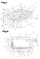
- Fig. 1
- einen Teil eines erfindungsgemäßen Formwerkzeuges in schaubildlicher und stark vereinfachter Darstellung;
- Fig. 2
- das erfindungsgemäße Formwerkzeug nach
Fig. 1 in Stirnansicht ge- schnitten, mit auf dem unteren Werkzeugteil aufgesetzten oberen Werk- zeugteil, in vereinfachter schematischer Darstellung; - Fig. 3
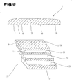
- ein erfindungsgemäßes Formteil mit den diesen bildenden Schichten in voneinander getrennter Lage sowie einem Teilabschnitt des Formwerk- zeuges, in schaubildlich vereinfachter Darstellung;
- Fig. 4
- ein weiteres Formwerkzeug zur Durchführung des erfindungsgemäßen Verfahrens in Stirnansicht, in geschnittener und stark vereinfachter, sche- matischer Darstellung;
- Fig. 5
- den erfindungsgemäßen Formteil in Seitenansicht geschnitten, in ent- spannter Lage nach Entnahme aus dem Formwerkzeug;
- Fig. 6
- zeigt einen Aufbau der verschiedenen Schichten eines Schichtenverbun- des zur Herstellung eines Formteils durch Hinterspritzen mit einem Kunststoff in explosionsartiger, schaubildlicher Darstellung;
- Fig. 7
- eine Ausführungsvariante eines erfindungsgemäßen Formteils in Explosi- onsdarstellung und stark vereinfachter Darstellung; und
- Fig. 8
- eine andere Ausführungsform eines erfindungsgemäßen Formteils in Sei- tenansicht, in geschnittener und stark vereinfachter, schematischer Dar- stellung.
- Fig. 1
- a part of a mold according to the invention in diagrammatic and highly simplified representation;
- Fig. 2
- after the mold according to the invention
Fig. 1 cut in front view, with upper tool part placed on the lower tool part, in simplified schematic representation; - Fig. 3
- an inventive molding with the layers forming them in a separate position and a portion of the Formwerk- tool, in diagrammatically simplified representation;
- Fig. 4
- another mold for performing the method according to the invention in front view, in a cut and highly simplified, schematic representation;
- Fig. 5
- cut the molding according to the invention in side view, in a relaxed position after removal from the mold;
- Fig. 6
- shows a structure of the various layers of a layer composite for the production of a molded part by injection molding with a plastic in an explosive, perspective view;
- Fig. 7
- an embodiment of a molded part according to the invention in exploded view and greatly simplified representation; and
- Fig. 8
- another embodiment of a molded part according to the invention in side view, in a sectioned and greatly simplified, schematic representation.
Einführend sei festgehalten, dass in den unterschiedlich beschriebenen Ausführungsformen gleiche Teile mit gleichen Bezugszeichen bzw. gleichen Bauteilbezeichnungen versehen werden, wobei die in der gesamten Beschreibung enthaltenen Offenbarungen sinngemäß auf gleiche Teile mit gleichen Bezugszeichen bzw. gleichen Bauteilbezeichnungen übertragen werden können. Auch sind die in der Beschreibung gewählten Lageangaben, wie z.B. oben, unten, seitlich usw. auf die unmittelbar beschriebene sowie dargestellte Figur bezogen und sind bei einer Lageänderung sinngemäß auf die neue Lage zu übertragen. Weiterhin können auch Einzelmerkmale oder Merkmalskombinationen aus den gezeigten und beschriebenen unterschiedlichen Ausführungsbeispielen für sich eigenständige, erfinderische oder erfindungsgemäße Lösungen darstellen.By way of introduction, it should be noted that in the differently described embodiments, the same parts are provided with the same reference numerals or the same component names, wherein the disclosures contained in the entire description can be mutatis mutandis to the same parts with the same reference numerals or component names. Also, the location information chosen in the description, such as top, bottom, side, etc. related to the immediately described and illustrated figure and are to be transferred to the new situation mutatis mutandis when a change in position. Furthermore, individual features or combinations of features from the illustrated and described different embodiments may represent for themselves, inventive or inventive solutions.
In den
Jeder der beiden Werkzeugteile 2 und 3 weist Formwandteile 4 und 5 auf, die zusammen eine einen Formhohlraum 6 umgrenzende Formwand 7 bilden. Im unteren Werkzeugteil 3 kann, wie beispielsweise in
Zum Fixieren der Lederschicht 10 im Formhohlraum 6, so dass diese in einer bestimmten, vordefinierten Position mit dem zu hinterspritzenden Kunststoff 17 verbunden werden kann, können unterschiedliche Haltevorrichtungen 12 vorgesehen sein. So ist es beispielsweise möglich, dass die einzulegende Lederschicht 10 mit einem Haftmittel versehen ist, welches ein Anhaften an der Teilfläche 8 der Formwand 7 ermöglicht. Es ist aber auch möglich, die Lederschicht 10 beispielsweise durch einen Unterdruck zu positionieren, wozu die Teilfläche 8 der Formwand 7 zumindest partiell durch zumindest ein für Luft poröses Einsatzelement gebildet sein kann. Es können aber auch in der Teilfläche 8 Ansaugöffnungen 13 vorgesehen sein, die über Kanäle 14 und Absaugleitungen 15 mit einem Unterdruckerzeuger 16 verbunden sein können. Es ist jedoch auch jede andere aus dem Stand der Technik bekannte Technologie zur positionierten Halterung und Fixierung der in den Formhohlraum 6 einzulegenden Lederschicht 10 verwendbar.To fix the
Die Teilfläche 8, auf welcher zumindest zum Teil die Lederschicht 10 zum Hinterspritzen mit einem Kunststoff 17 aus einer Spritzgießvorrichtung 18 aufgelegt wird, ist mit einer strukturierten Oberfläche ausgebildet, die an die Lederstruktur eines Naturleders angepasst ist.The
Dazu ist in der beispielsweise aus Stahl bestehenden Formwand 7 bzw. in dem unteren bzw. oberen Werkzeugteil 2, 3 eine Oberflächenstruktur ausgebildet.For this purpose, a surface structure is formed in the existing example of
Beispielsweise ist in den
Diese erhabenen Bereiche 19, die im fertigen Formteil 22 die die Ledernarbung bildenden Vertiefungen darstellen, können nun über die Teilfläche 8 unmittelbar in der Formwand 7 des unteren und/oder oberen Werkzeugteils 2 bzw. 3 angeordnet sein.These raised
Es ist aber auch möglich, mehrere Teilflächen 8 über die Formwand 7 verteilt anzuordnen, wenn mehrere Lederschichten 10 eingelegt werden.However, it is also possible to arrange a plurality of
Bevorzugt ist es aber auch zusätzlich oder anstelle dessen möglich, Abschnitte oder Teilbereiche der Teilfläche 8 oder die gesamte Teilfläche 8 durch einen oder mehrere Einsatzteile 21 auszubilden, die in den jeweiligen unteren und/oder oberen Werkzeugteil 2, 3 eingesetzt werden können.However, it is also possible in addition or instead to form sections or partial regions of the
Die Verwendung derartiger Einsatzteile 21 ermöglicht es, in der laufenden Produktion unterschiedliche Oberflächengestaltungen bzw. strukturierte Oberflächen mit demselben Formwerkzeug 1 herzustellen bzw. die strukturierte Oberfläche besser zu warten.The use of
Die strukturierte Oberfläche kann nun nach verschiedenen Methoden und Verfahren hergestellt werden. So ist es möglich, dass durch eine oder mehrere Schichten die erhabenen Bereiche 19 mittels PVD- (Physical Vapour Deposition) oder CVD-Verfahren (Chemical Vapour Deposition) auf Oberflächen abgeschieden werden. Beiden Verfahren ist gemeinsam, dass die Beschichtungsmaterialien aus der Dampfphase auf der Werkstückoberfläche abgeschieden werden. Beim PVD-Verfahren wird das Beschichtungsmaterial über die physikalischen Vorgänge des Verdampfens oder der Kathodenzerstäubung im Hochvakuum in die Dampfphase übergeführt und anschließend auf der zu beschichtenden Oberfläche niedergeschlagen. Beim CVD-Verfahren handelt es sich um die Abscheidung von Feststoffen aus der Gasphase, wobei die Gasphase im Gegensatz zu den PVD-Verfahren auf chemischem Weg erzeugt wird.The structured surface can now be produced by various methods and processes. It is thus possible for the raised
Besonders vorteilhaft ist es, wenn der Materialauftrag beispielsweise durch Nickel oder Nickellegierungen gebildet ist. Die durch Nickel oder Nickellegierungen gebildeten erhabenen Bereiche 19 in der Teilfläche 8 weisen eine sehr hohe Härte und damit auch eine hohe Standzeit für die durch den Spritzdruck hervorgerufenen Einprägungen in der Lederschicht 10 auf. Vor allem ist es mit durch im Stand der Technik bekannten Verfahren und Methoden möglich, die erhabenen Bereiche 19 in der Teilfläche 8 durch Abscheiden von Nickel oder Nickellegierungen aus der Dampfphase mit den zuvor erwähnten PVD- oder CVD-Verfahren herzustellen.It is particularly advantageous if the material application is formed, for example, by nickel or nickel alloys. The raised
Als besonders vorteilhaft kann sich hierbei erweisen, wenn das Einsatzteil 21, auf dem eine Teilfläche 8 oder ein Teil einer Teilfläche 8 angeordnet ist, vollständig aus Nickel oder einer Nickellegierung besteht.In this case, it can prove to be particularly advantageous if the
Es ist aber auch ohne weiters möglich, die erhabenen Bereiche 19 durch Auftragen von Zusatzmaterial und Erwärmung mittels eines Laserstrahls herzustellen oder andere geeignete Verfahren einzusetzen.But it is also readily possible to produce the raised
Anstelle des Herstellens der erhabenen Bereiche 19 ist es auch möglich, in der Teilfläche 8 die den erhabenen Bereichen 19 benachbarten, vertieften Bereiche 20 durch entsprechende Abtragverfahren, wie beispielsweise Funkenerosionsverfahren oder Teilchen- oder Laserstrahlung oder elektro-chemische Verfahren, abzutragen, so dass die erhabenen Bereiche 19, die die Vertiefungen in der Lederstruktur darstellen sollen und beim Herstellen des Formteils 22 in die Oberfläche der Ansichtsseite 9 der Lederschicht 10 eingeprägt werden sollen, zu bilden. Nachdem das Volumen der in der Lederstruktur vertieften Bereiche üblicherweise wesentlich geringer ist als das der erhabenen Bereiche in der Ansichtsseite 9 von Naturleder, werden in vorteilhafter Weise bei derartigen Naturlederstrukturen Verfahren zum Auftragen der erhabenen Bereiche 19 eingesetzt.Instead of producing the raised
Zur Herstellung von Formteilen 22 mit hoher Qualität werden üblicherweise Lederschichten 10 aus Naturleder verwendet. Während nun bei den bisher bekannten Verfahren zum Verstärken von Lederschichten 10 durch Hinterspritzen mit Kunststoffmaterial 17 die natürliche Oberflächenstruktur aufgrund der hohen Temperaturen und des hohen Spritzdruckes verloren gehen, da die Oberfläche an der hochpolierten Formfläche der Formwand 7 flachgedrückt wurde, ist durch die Anordnung der strukturierten Oberfläche zumindest in jenen Teilflächen 8, in welchen eine Lederschicht 10 eingelegt wird, sichergestellt, dass auch nach dem Hinterspritzen mit dem Kunststoffmaterial 17 auf der Ansichtsseite 9 eine lederartige Oberflächenstruktur erhalten bleibt bzw. diese in die Oberfläche der Ansichtsseite 9 bleibend und dauerhaft eingeprägt bzw. eingeformt wird.To produce high quality molded
Ein Vorteil der erfindungsgemäßen Lösung ist beispielsweise, dass nunmehr jegliche Art von Leder, beispielsweise auch Lederarten, die üblicherweise nur eine sehr schwache und zart ausgeprägte bzw. aber auch keine Strukturierung ihrer Oberfläche aufweisen; mit einer für den Konsumenten zur Darstellung der Hochwertigkeit der Ansichtsseite 9 benötigten strukturierten Oberfläche umgeformt werden können. Damit können auch Ledermaterialien, die teilweise strapazfähiger sind als jene, die eine extrem starke und gut erkennbare Narbung aufweisen, für die Herstellung hochwertiger Formteile 22 verwendet werden.An advantage of the solution according to the invention is, for example, that now any type of leather, for example, leathers, which usually have only a very weak and delicately pronounced or no structuring of their surface; can be reshaped with a structured surface required for the consumer to represent the high quality of the
An dieser Stelle sei nur der Ordnung halber angemerkt, dass sämtliche Ausführungen, die für die Verwendung von Lederschichten 10 in Verbindung mit Naturleder gebildet werden, auch gleichermaßen für Kunstleder zuzurechnen sind. Es ist mit dem vorhergehenden Verfahren natürlich auch möglich, Kunstlederschichten mit einer dem Naturleder entsprechenden Narbung in dem erfindungsgemäßen Formwerkzeug 1 herzustellen.It should be noted at this point only for the sake of order that all versions that are formed for the use of leather layers 10 in conjunction with natural leather, are equally attributable to artificial leather. Of course, it is also possible with the preceding method to produce artificial leather layers with a grain corresponding to the natural leather in the
Zweckmäßig ist es aber auch, in diesem Zusammenhang in Verbindung mit der Herstellung der strukturierten Oberfläche auf der eingelegten Lederschicht 10, die die optische Erkennbarkeit und den Hinweis auf die Verwendung von Leder für den Benutzer einfach ermöglicht, auch die Haptik für derart hergestellte Formteile 22 entsprechend dem gewohnten Gefühl von Naturleder zu vermitteln und auch die elastischen Eigenschaften der Lederschicht 10 bei verschiedenen herzustellenden Formteilen 22 beizubehalten. Um dies zu ermöglichen, ist es nun vorteilhaft, wenn auf der Innenseite 11 der Lederschicht 10 eine Sperrschicht 23 aufgebracht wird.It is also expedient, however, in this connection in connection with the production of the structured surface on the inserted
Diese Sperrschicht 23 hat nun die Aufgabe, das Eindringen des Kunststoffmaterials 17, welches während des Einspritzvorganges, das mit der Spritzgießvorrichtung 18 über die Einspritzöffnung 24 in den Formhohlraum 6 eingebracht wird, in die meist offenporige Innenseite 11 bzw. Fleischseite der Lederschicht 10, vor allem dann, wenn es sich um Naturleder handelt, zu verhindern. Damit wird gleichzeitig verhindert, dass der eingebrachte Kunststoff 17 die Lederschicht 10 in sich verstärkt und versteift und kann eine hohe, dem ursprünglichen räumlichen Verformungsverhalten einer Naturlederschicht entsprechende Elastizität der Lederschicht 10 auch nach dem Herstellen des entsprechenden Formteils 22 erhalten werden. Dies ist besonders dann von Vorteil, wenn dünnwandige Formteile 22, die wie beispielsweise bei Uhrenarmbändern, Gürteln oder dgl. sehr elastisch sein müssen, verwendet werden.This
Gleiches gilt für Anwendungen in der Möbel- und Automobilindustrie, bei Lederform-und Verkleidungsteilen, wie beispielsweise bei Sitzen, Armlehnen, Schalthebeln, Sonnenblenden oder dergleichen, die trotz einer hoher Beanspruchung eine gute Elastizität aufweisen sollen.The same applies to applications in the furniture and automotive industry, in leather moldings and trim parts, such as seats, armrests, levers, sun visors or the like, which should have a good elasticity despite high stress.
Eine noch höhere Elastizität kann dabei erreicht werden, wenn diese Sperrschicht 23 unter Zwischenschaltung einer Kleberschicht 25 mit der Innenseite 11 der Lederschicht 10 verbunden wird. Dadurch kann auch bei etwas dickeren Kunststoffschichten 26, die mit der Lederschicht 10 bzw. der Sperrschicht 23 durch Anspritzen bewegungsfest verbunden werden, eine hohe räumliche Relativbewegung zwischen dem steifen Kunststoffmaterial 17 und der Lederschicht 10 erzielt werden.An even higher elasticity can be achieved if this
Für die mit der Lederschicht 10 oder der Sperrschicht 23 zu verbindende Kunststoffschicht 26 können die unterschiedlichsten Materialien verwendet werden. So können diese vor allem hinsichtlich ihrer Festigkeit und Elastizität bzw. Temperatureigenschaften auf den jeweiligen Anwendungsfall im Rahmen des Fachwissens eines auf diesem Gebiet tätigen Fachmanns ausgelegt werden.For the
Es ist aber ohne weiters auch möglich, dass die Kunststoffschicht 26 zwischen zwei Lederschichten 10 eingebracht wird, wobei die Lederschichten 10 an einander gegenüberliegenden Teilflächen 8 im Formhohlraum 6 positioniert und gehalten werden können. Es ist unter anderem aber auch möglich, dass in der herzustellenden Kunststoffschicht 26 während des Hinterspritzens der Lederschicht 10 bzw. der Sperrschicht 23 entsprechende Aufnahmen, Halteteile und Fixierelemente und Schnappvorrichtungen mit hergestellt werden, um den Formteil 22 auf Halte- oder Stützstrukturen in der gewünschten Art und Weise befestigen zu können.But it is without further possible that the
Für besondere Anwendungsfälle ist es auch möglich, dass die Kunststoffschicht 26 durch mehrere übereinander liegende Lagen aus gleichartigen oder unterschiedlichen, beispielsweise unterschiedlich eingefärbten oder mit unterschiedlichen physikalischen Eigenschaften versehene Kunststoffmaterialien 17 gebildet ist; ferner können derartige unterschiedliche Kunststoffschichten 26 auch nebeneinander über die gesamte Höhe des Formteils 22 zueinander benachbart angeordnet sein.For special applications, it is also possible that the
Beim Herstellen von Formwerkzeugen 1 nach dem erfindungsgemäßen Verfahren wird derart vorgegangen, dass die die Abschnitte oder Teilflächen 8 zur Auflage der Lederschichten 10 bildenden Teilflächen 8 der Formwand 7 oder diese Teilflächen 8 bildenden Oberflächenteile auf die Einsatzteile 21 erhabene Bereiche durch das Abscheiden von Nickel oder Nickellegierungen aus der Dampfphase hergestellt werden.When producing
Dieser Auftrag von Nickel oder Nickellegierungen kann in einem oder mehreren aufeinander folgenden Arbeitsschritten erfolgen und ermöglicht die Herstellung von in sich verlaufenden und unterschiedlich hohen erhabenen Bereichen 19. Vor allem ist damit eine Übernahme von Daten aus einer elektronischen Bauteilvermessung des Oberflächenverlaufs von Naturleder unmittelbar zur Herstellung der entsprechend benötigten erhabenen Bereiche 19 zur Ausbildung der Oberflächenprägung der Lederschichten 10 möglich.This application of nickel or nickel alloys can be carried out in one or more successive steps and allows the production of self-extending and different high raised
Beim Herstellen eines Formteils 22, bestehend aus einer Lederschicht 10 und einer Kunststoffschicht 26, wird nun derart vorgegangen, dass eine Lederschicht 10 mit ihrer Ansichtsseite 9 auf die dafür vorgesehene Formwand 7 bzw. Teilfläche 8 dieser Formwand 7 aufgelegt wird. Über die Mittel der Haltevorrichtung 12, beispielsweise einer partiell haftenden Kleberschicht oder Ansaugöffnungen 13 eines Unterdrucksystems kann die Lederschicht 10 auf dieser Formwand 7 bzw. Teilfläche 8 positioniert gehalten werden. Daraufhin wird das Formwerkzeug 1 durch Aufeinandersetzen des unteren und oberen Werkzeugteils 2 bzw. 3 geschlossen und ein nach Außen hin abgeschlossener Formhohlraum 6 gebildet. Auf der von der Ansichtsseite 9 der Lederschicht 10 abgewandten Seite dieser Lederschicht 10 bzw. der auf dieser aufgebrachten Sperrschicht 23 wird dann durch die Einspritzöffnung 24 der Kunststoff 17 mit hoher Temperatur und hohem Druck mittels der Spritzgießvorrichtung 18 eingebracht. Durch den sich im Formhohlraum 6 aufbauenden Spritzdruck wird die Lederschicht 10 mit ihrer Ansichtsseite 9 an die strukturierte Oberfläche der Teilfläche 8 angepresst. Durch den Druck des die Kunststoffschicht 26 bildenden Kunststoffmaterials 17 wird die Lederschicht 10 derart stark gegen die Oberfläche der Teilfläche 8 mit ihrer strukturierten Oberflächenform gedrückt, dass sich die erhabenen Bereiche 19 in die Ansichtsseite 9 der Lederschicht 10 einpressen bzw. diese Ansichtsseite 9 prägen, so dass diese die strukturierte Oberfläche der Teilfläche 8 übernimmt.When producing a molded
In der
Der Formteil 22 umfasst hier wiederum die Lederschicht 10 mit ihrer Ansichtsseite 9 sowie der davon abgewendeten Innenseite 11. Die Sperrschicht 23 ist der von der Ansichtsseite 9 abgewendeten Innenseite 11 der Lederschicht 10 zugeordnet. Zwischen der Sperrschicht 23 und der Lederschicht 10 kann zur Verbesserung der Hafteigenschaften sowie der Verbindung zwischen den beiden Schichten eine oder mehrere Kleberschichten 25 vorgesehen sein. Eine derartige Schicht kann auch zusätzlich noch auf der der Kunststoffschicht 26 zugewendeten Oberfläche bzw. Seite der Sperrschicht 23 angeordnet werden.Here again, the molded
Dieses Halbfertigprodukt bzw. Vorprodukt kann vor dem eigentlichen Herstellen des Formteiles 22 hergestellt werden, indem die Sperrschicht 23 gegebenenfalls unter Zwischenschaltung der Kleberschicht 25 an die Innenseite 11 der Lederschicht 10 angebracht wird. Dieses Aufbringen der Sperrschicht 23 kann aber auch durch einen Kaschiervorgang oder andere aus dem Stand der Technik bekannte Verbindungsvorgänge erfolgen.This semi-finished product or intermediate product can be prepared before the actual production of the molded
Dieser vorbereitete Schichtaufbau des Halbfertigprodukts kann großflächig hergestellt werden und noch vor dem Einlegen in das Formwerkzeug 1 durch einen entsprechenden Zuschnittvorgang für die Herstellung des Formteils 22 konfektioniert werden.This prepared layer structure of the semi-finished product can be produced over a large area and assembled before being placed in the
Das erfindungsgemäße Verfahren wird anhand eines weiteren Formwerkzeuges 1, wie es in
Das Formwerkzeug 1 umfasst die Werkzeugteile 2, 3. Formwandteile 4 und 5 der Werkzeugteile 2 und 3 bilden zusammen die den Formhohlraum 6 umgrenzende Formwand 7. Auf einer Teilfläche 8 in einem der Werkzeugteile, im vorliegenden Fall im unteren Werkzeugteil 3, kann beispielsweise eine zu einer Oberflächenstruktur eines Naturleders komplementäre Oberflächenstruktur ausgebildet sein, auf der eine Ansichtsseite 9 einer Lederschicht 10 zur Anlage gebracht werden kann. Diese Ansichtsseite 9 ist üblicherweise glatt und strapazfähig, während die gegenüber liegende Innenseite 11, die Fleischseite, meist sehr grobporig und fasrig ausgebildet ist.The
Um eine derartige Lederschicht 10 auf einer Formwand eines Formwerkzeuges 1 zu positionieren, ist üblicherweise eine Haltevorrichtung 12 vorgesehen, die beispielsweise durch Ansaugöffnungen 13, die über einen Kanal 14 mit einem Unterdruckerzeuger verbunden sind, oder eine Haftschicht gebildet sein kann. Durch den Unterdruck kann die Lederschicht 10 in einer exakten Position im Formhohlraum 6 gehalten und positioniert werden.In order to position such a
Auf der Lederschicht 10 ist weiterhin eine Zwischenschicht 27 und eine Sperrschicht 28 angeordnet. Die Zwischenschicht 27 ist in zur Innenseite 11 der Lederschicht 10 senkrechter Richtung zumindest teilweise bleibend verformbar und aus Kunststoff hergestellt. Auf der von der Lederschicht 10 abgewendeten Seite der Zwischenschicht 27 ist eine Sperrschicht 28 ausgebildet oder als eigene Schicht auf dieser Zwischenschicht 27 angeordnet.On the
Die auf die Formwand 7 bzw. eine Teilfläche 8 der Formwand 7 aufgelegte Lederschicht 10 wird mit einem Kunststoff 29 zur Herstellung einer Kunststoffschicht 30 hinterspritzt.The
Dabei kann es vorteilhaft sein, zur Beibehaltung einer einem Naturleder angepassten Oberflächenstruktur und Haptik der Lederschicht 10 und zur Schaffung einer derartigen Oberflächenstruktur, die Formwand 7 bzw. die Teilfläche 8 mit einer der Lederstruktur eines Naturleders angepassten strukturierten Oberfläche auszubilden. Dazu besteht, wie schematisch dargestellt, die strukturierte Oberfläche in der Teilfläche 8 aus erhabenen Bereichen 31 und diesen benachbarten, vertieften Bereichen 32 und ist die Struktur der erhabenen und vertieften Bereiche 31, 32 komplementär zur gewünschten Oberflächenstruktur eines Naturleders, von dem diese Struktur üblicherweise übernommen bzw. abgenommen wird. Die erhabenen und vertieften Bereiche 31, 32 können mit verschiedenen Methoden und Verfahren hergestellt werden.It may be advantageous, for maintaining a natural leather adapted surface structure and feel of the
Bei dem vorliegenden erfindungsgemäßen Verfahren wird nun der Kunststoff 29 zur Bildung eines Formteils 33 auf die Sperrschicht 28 aufgebracht. Der Kunststoff 29 wird dabei über eine Einspritzöffnung von einer schematisch angedeuteten Spritzgießvorrichtung eingespritzt und an die Sperrschicht 28 angeformt. Um eine Verlagerung zwischen der Lederschicht 10, der Zwischenschicht 27 und der Sperrschicht 28 während des Einbringens des Kunststoffes 29 in den Formhohlraum 6 zu vermeiden, können zwischen diesen einzelnen Schichten Kleberschichten 34, die beispielsweise auch durch Druck und/oder Temperatur aktivierbare Klebefolien 35, 36 gebildet sein können, angeordnet sein.In the present inventive method, the plastic 29 is then applied to the
Durch den beim Einbringen des Kunststoffes 29 in den Formhohlraum 6 sich aufbauenden Druck, bedingt durch den Einspritzdruck des Kunststoffes 29, werden die Oberflächenstrukturen, die in dem Formwandteil 4, 5 bzw. in einer Teilfläche 8 derselben angeordnet sind, in die Oberfläche der Ansichtsseite 9 der Lederschicht 10 bzw. Kunstlederschicht eingeprägt oder es wird die Lederschicht 10 insgesamt räumlich verformt, wobei die Lederschicht 10 - wie es besser aus
Wie aus der Darstellung der
In Abhängigkeit von den für die Zwischenschicht 27 verwendeten Materialien, insbesondere einem elastisch verformbaren Kunststoffschaum und der Eindruckhärte dieses Kunststoffschaums, bleibt die Stärke bzw. Dicke dieser Zwischenschicht 27 während des Einspritzvorgangs des Kunststoffes 29 unverändert oder wird auch die Stärke bzw. Dicke dieser Zwischenschicht 27 durch plastische Verformung des Materials dieser Zwischenschicht 27 verringert.Depending on the materials used for the
Je nach dem eingesetzten bzw. gewünschten Kunststoffmaterial, und zwar in Abhängigkeit davon, ob beispielsweise der Kunststoffschaum, aus dem die Zwischenschicht 27 hergestellt ist, elastisch rückstellbare Eigenschaften aufweist oder nicht, bleibt diese Dicke 37 auch nach dem Entnehmen des Formteils 33 erhalten.Depending on the plastic material used or desired, depending on whether, for example, the plastic foam from which the
Wird dagegen, wie aus dem Vergleich der Darstellungen des Formteils 33 in den
Diese Anordnung der Zwischenschicht 27 ermöglicht nun die Elastizitätseigenschaften der Lederschicht 10 bzw. des gesamten Formteils 33 an unterschiedlichste Anwendungsfälle und Eigenschaften anzupassen.This arrangement of the
So kann durch entsprechende Bemessung der Zwischenschicht 27 eine Dämpfung bei einem Auftreffen von Gegenständen oder Personen auf derartige Formteile 33 entsprechend voreingestellt werden. Es ist aber auch möglich, die Expansions- und Dehnungseigenschaften der Lederschicht 10 bzw. des gesamten Formteils 33 bei unterschiedlichen Temperaturen oder Belastungen zu verändern. Darüber hinaus können auch entsprechende andere physikalische Eigenschaften durch die Dicke dieser Zwischenschicht und deren physikalischen und chemischen Eigenschaften, wie beispielsweise eine Schalldämmung, erzielt werden.Thus, by appropriate design of the
Wird die Zwischerischicht 27 aus einem Material herstellt, welches elastisch rückstellbare Eigenschaften aufweist, so ist es auch möglich, dass sich bei einer Druckbelastung des Formteils 1 in einzelnen Bereichen oder über die ganze Fläche, die Oberfläche der Lederschicht 10 wieder elastisch in ihre Ausgangslage rückstellen kann, so dass eine hohe Qualität und eine lange Benutzungsdauer auch bei entsprechenden mechanischen Beanspruchungen solcher Formteile 33 erzielt werden kann.If the
Bevorzugt werden für diese Zwischenschicht 27 elastisch verformbare Kunststoffschäume, wie z.B. aus Polyurethan (PUR), Polyethylen (PE), Polyimid (PI), Polyether, Silikon, Silikonelastomer, Memoryschaum, offenporigen Polyurethanschaum, offenporigen Latexschaum und dergleichen, eingesetzt bzw. beliebig miteinander kombiniert, wobei der Memoryschaum ein Polyurethanschaum auf Esterbasis mit ausgeprägtem viscoelastischem Verhalten ist. Für die Wirkung dieser Zwischenschicht 27 ist es auch vorteilhaft, wenn die Eindrucktiefe dieser Zwischenschicht 27 und in Verbindung damit deren Stärke bzw. Dicke derart bemessen wird, dass die bleibende Verformung des Kunststoffmaterials bzw. die Eindrucktiefe durch den Spritzdruck beim Einspritzen des Kunststoffes 29 geringer ist, als die Stärke bzw. Dicke der Zwischenschicht 27 beim Einlegen in das Formwerkzeug 1.For this
Durch die Ausbildung der Sperrschicht 28 wird gleichzeitig verhindert, dass der plastifizierte Kunststoff 29 während des Einspritzens in den Formhohlraum 6 in die Zwischenschicht 27 bzw. in die Innenseite der Lederschicht 10 eindringen kann. Damit bleiben die Elastizitätseigenschaften der Zwischenschicht 27 und der Lederschicht 10 auch beim Aushärten des Kunststoffes 29, der üblicherweise eine höhere Festigkeit und geringere räumliche Verformbarkeit als die Lederschicht 10 und die Zwischenschicht 27 aufweist, erhalten. Es tritt keine Versteifung der Schaumstoffstruktur der Zwischenschicht 27 durch eingedrungenen, sich während des Abkühlens verfestigenden Kunststoff 29 der Kunststoffschicht 30 ein.The formation of the
In
Diese Lederschicht 10 ist über eine Kleberschicht 34 mit der Zwischenschicht 27 und diese über eine weiter Kleberschicht 34 mit der Sperrschicht 28 verbunden.This
Auf diese Sperrschicht 28, die ein Durchdringen des plastifizierten Kunststoffes 29 verhindert, wird der Kunststoff 29 aufgespritzt und durch den Spritzvorgang und die Erwärmung und die durch den Kunststoff gegebenen Eigenschaften an die Sperrschicht 28 angeformt. Damit wird nicht nur eine in senkrechter Richtung zur Lederschicht 10 voreinstellbare Verformung im Zusammenhang mit den physikalischen Eigenschaften vor allem der Zwischenschicht 27 sowie deren Stärke bzw. Dicke erzielt, sondern aufgrund des mehrschichtigen Aufbaus kann sich auch die Lederschicht 10, bedingt durch die Relativbeweglichkeiten, in Abhängigkeit von der Restelastizität der Kleberschicht 34 gegenüber der Zwischenschicht 27 und der Sperrschicht 28 bzw. dem Kunststoff 29 der Kunststoffschicht 30 in beliebiger Richtung in der Ebene der Lederschicht 10 verformen bzw. verlagern und verschieben, so dass auch bei starken schlagartigen Beanspruchungen mit spitzeren Objekten ein Aufplatzen oder Zerreißen der Lederschicht 10, vor allem auch bei dünneren Lederschichten 10, verhindert werden kann. Damit wird eine hoch strapazierbare Oberfläche im Lederdesign geschaffen. Durch die entsprechende Ausbildung der Kunststoffschicht 30 können gleichzeitig zur Befestigung des Formteils 33 z.B. durch das Anformen und das Einformen von Befestigungsteilen, Aufnahmen oder Schnappvorrichtungen geschaffen werden.On this
Bei der Ausführungsvariante des Formteils 33 in
Bei dem in
Die Sperrschicht 23, 28 kann dabei durch ein den Einflüssen der Witterung, der UV-Strahlung oder den mechanischen Beanspruchungen einen hohen Widerstand entgegensetzendes Material, wie beispielsweise PVC, PMMA, PP, PE, PETP oder dergleichen gebildet sein. Diese verschiedenen Materialien können zusätzlich mit verschiedenen Stabilisatoren oder dergleichen versetzt sein, um beispielsweise den Durchtritt von UV oder sonstigen Strahlungen möglichst zu unterbinden.The
Die Sperrschicht 23, 28 kann auch mehrere Lagen umfassen und beispielsweise aus einer Lage aus Textil oder einem Gitter bzw. Netz oder einer Matte, insbesondere aus Metall oder beliebigen anderen Fasern bzw. Fäden oder einem Gewirke bzw. Vlies, verstärkt sein. Es ist aber auch möglich, die Sperrschicht 23, 28 beispielsweise durch eine bedruckte Lage aus Papier herzustellen. Sie kann aber ebenso durch beliebige Kunststoffe, Kunststofffolien oder Formkörper oder dergleichen gebildet sein.The
Diese Sperrschicht 23, 28 kann über die Kleberschicht 25, 34 mit der Lederschicht 10 oder zumindest einer der Zwischenschichten 27, 40 verbunden sein, die die Lederschicht 10 vor übermäßigen Druck-, Temperatur- oder Scherbeanspruchungen während des Aufbringens der Kunststoffschicht 26, 30 schützen soll. Um den hohen Beanspruchungen während des Einbringens des flüssigen Kunststoffmaterials 17, 29 mit hoher Temperatur zu widerstehen, kann die Sperrschicht 23, 28 aus einem Polytetrafluorethylen gebildet sein. Zur vollflächigen Verbindung der Sperrschicht 23, 28 mit der Kunststoffschicht 26, 30 kann auf die Sperrschicht 23, 28 eine zusätzliche Schicht bestehend aus einem Haftvermittler aufgebracht sein.This
Als Werkstoffe zur Bildung der Sperrschicht 23, 28, der Kleberschicht 25, 34 sowie der Kunststoffschicht 26, 30 können die verschiedensten Materialien, vor allem aber auch Kunststofffolien, vorteilhaft aus der Gruppe der nachstehenden, beispielhaft und nicht vollständig aufgezählten Materialien, wie PVC (hart, weich), PC, PET, PET-P, PS, PA, CA, PP, PE, PMMA, ABS und EAA gewählt werden. Für die Herstellung der Kunststoffschicht 26, 30, vor allem durch einen Spritzgussvorgang, können grundsätzlich alle Kunststoffmaterialien, die dafür geeignet sind, verwendet werden, wobei jedoch beispielsweise Materialien wie PP, POM, ABS, SAN, PMMA, TPU, EAA, PUR, PC verwendbar sind.As materials for forming the
Der in der Beschreibung und in den Ansprüchen verwendete Begriff Leder für die Lederschicht 10 umfasst dabei Naturleder als auch Kunstleder. Bei Kunstleder wird ein Verbund von textilem Gewebe mit einer Beschichtung aus Kunststoff verstanden. Hierbei handelt es sich um Naturfasergewebe oder Kunstfasern, die mit einer weichen PVC-Schicht beschichtet sind. Diese Beschichtungen können je nach Anwendungsfall kompakt oder geschäumt ausgeführt werden. In aller Regel sind die Oberflächen noch genarbt oder werden beim Herstellen der Kunststoffschicht 26, 30 genarbt, sodass sie einer Lederstruktur entsprechen. Anwendungsbeispiele für Kunstleder sind Armbänder, Gürtel, Ausstattungs- und Verkleidungsteile in der Automobilindustrie, Schuhe, Taschen, Bälle (z.B. Fußbälle). Moderne Kunstleder sind häufig anstelle der PVC-Beschichtung mit einer Polyurethan-Beschichtung versehen.The term leather used in the description and in the claims for the
Für die Sperrschicht 23, 28 können beispielsweise auch Folien oder Lagen aus den vorgenannten Materialien verwendet werden.For the
Für die Kleberschichten 25, 34 können alle aus dem Stand der Technik bekannten unterschiedlichen Klebefolien oder Kleberschichten, die auch flüssig aufgetragen werden können, eingesetzt werden.For the
Der Ordnung halber sei abschließend darauf hingewiesen, dass zum besseren Verständnis des Aufbaus des Formwerkzeuges 1 sowie des Formteils 22, 33 dieser bzw. dessen Bestandteile teilweise unmaßstäblich und/oder vergrößert und/oder verkleinert dargestellt wurden.For the sake of order, it should finally be pointed out that for a better understanding of the structure of the
Die den eigenständigen erfinderischen Lösungen zugrunde liegende Aufgabe kann der Beschreibung entnommen werden.The problem underlying the independent inventive solutions can be taken from the description.
Die Ausführungsbeispiele zeigen mögliche Ausführungsvarianten des Formwerkzeuges 1 sowie des Formteils 22, 33, wobei an dieser Stelle bemerkt sei, dass die Erfindung nicht auf die speziell dargestellten Ausführungsvarianten eingeschränkt ist, sondern vielmehr auch diverse Kombinationen der einzelnen Ausführungsvarianten untereinander möglich sind und diese Variationsmöglichkeiten aufgrund der Lehre zum technischen Handeln durch gegenständliche Erfindung im Können des auf diesem technischen Gebiet tätigen Fachmannes liegt. Es sind also auch sämtliche denkbaren Ausführungsvarianten, die durch Kombinationen einzelner Details der dargestellten und beschriebenen Ausführungsvariante möglich sind, vom Schutzumfang mit umfasst.The embodiments show possible embodiments of the
Vor allem können die einzelnen in den
- 11
- Formwerkzeugmold
- 22
- oberer WerkzeugteilUpper tool part
- 33
- unterer Werkzeugteillower tool part
- 44
- FormwandteilMold wall part
- 55
- FormwandteilMold wall part
- 66
- Formhohlraummold cavity
- 77
- Formwandmold wall
- 88th
- Teilflächesubarea
- 99
- Ansichtsseiteview page
- 1010
- Lederschichtleather layer
- 1111
- Innenseiteinside
- 1212
- Haltevorrichtungholder
- 1313
- Ansaugöffnungsuction
- 1414
- Kanalchannel
- 1515
- Absaugleitungsuction
- 1616
- UnterdruckerzeugerVacuum generator
- 1717
- Kunststoffplastic
- 1818
- Spritzgießvorrichtunginjection molding
- 1919
- BereichArea
- 2020
- BereichArea
- 2121
- Einsatzteilinsert
- 2222
- Formteilmolding
- 2323
- Sperrschichtjunction
- 2424
- EinspritzöffnungInjection port
- 2525
- Kleberschichtadhesive layer
- 2626
- KunststoffschichtPlastic layer
- 2727
- Zwischenschichtinterlayer
- 2828
- Sperrschichtjunction
- 2929
- Kunststoffplastic
- 3030
- KunststoffschichtPlastic layer
- 3131
- BereichArea
- 3232
- BereichArea
- 3333
- Formteilmolding
- 3434
- Kleberschichtadhesive layer
- 3535
- Klebefolieadhesive film
- 3636
- Klebefolieadhesive film
- 3737
- Dickethickness
- 3838
- Dickethickness
- 3939
- Dickethickness
- 4040
- Zwischenschichtinterlayer
- 4141
- BereichArea
- 4242
- BereichArea
Claims (42)
Priority Applications (1)
| Application Number | Priority Date | Filing Date | Title |
|---|---|---|---|
| EP20070019221 EP2042291B1 (en) | 2007-09-29 | 2007-09-29 | Method for producing a moulded part and moulded part |
Applications Claiming Priority (1)
| Application Number | Priority Date | Filing Date | Title |
|---|---|---|---|
| EP20070019221 EP2042291B1 (en) | 2007-09-29 | 2007-09-29 | Method for producing a moulded part and moulded part |
Publications (2)
| Publication Number | Publication Date |
|---|---|
| EP2042291A1 true EP2042291A1 (en) | 2009-04-01 |
| EP2042291B1 EP2042291B1 (en) | 2014-04-23 |
Family
ID=38988271
Family Applications (1)
| Application Number | Title | Priority Date | Filing Date |
|---|---|---|---|
| EP20070019221 Expired - Fee Related EP2042291B1 (en) | 2007-09-29 | 2007-09-29 | Method for producing a moulded part and moulded part |
Country Status (1)
| Country | Link |
|---|---|
| EP (1) | EP2042291B1 (en) |
Cited By (6)
| Publication number | Priority date | Publication date | Assignee | Title |
|---|---|---|---|---|
| WO2015124660A1 (en) * | 2014-02-19 | 2015-08-27 | Johnson Controls Interiors Gmbh & Co. Kg | Multilayered molded body for vehicle interiors and method for producing such molded bodies |
| US20190021534A1 (en) * | 2017-07-21 | 2019-01-24 | Xiamen Sheep Anti-Fatigue Mat Co.,Ltd | Anti-fatigue mats and methods for making the same |
| CN111941737A (en) * | 2020-09-18 | 2020-11-17 | 常熟市汽车饰件股份有限公司 | Local reinforced injection molding method for injection molding product with glass fiber composite sheet embedded on surface |
| EP3838575A1 (en) | 2019-12-20 | 2021-06-23 | Engelbert Strauss GmbH & Co. KG | Method of manufacturing an insole and injection or casting mould |
| DE102020122779B3 (en) | 2020-09-01 | 2022-03-03 | J. & F. Krüth GmbH | Process for producing, processing, changing and/or refining a mold and injection molding tool |
| CN114179387A (en) * | 2021-12-27 | 2022-03-15 | 广州海天塑胶有限公司 | Leather coating process for plastic part in mold |
Citations (3)
| Publication number | Priority date | Publication date | Assignee | Title |
|---|---|---|---|---|
| US5650115A (en) * | 1992-08-31 | 1997-07-22 | Plastic Mold Technology Incorporated | Method for making molded air bag covers and other articles with integral cover layer of leather |
| DE19926470A1 (en) * | 1999-06-10 | 2000-12-14 | Bayerische Motoren Werke Ag | Application of barrier layer to back of decorative covering, e.g. leather, involves spraying on multi-component material while covering is in a mold |
| DE10119494A1 (en) * | 2001-04-20 | 2002-10-24 | Basf Ag | Preparation of profiled leather object useful for automobile upholstery and instrument panels, having at least one leather layer and a protective layer made from a thermoplastic polymer bonded to the leather layer |
-
2007
- 2007-09-29 EP EP20070019221 patent/EP2042291B1/en not_active Expired - Fee Related
Patent Citations (3)
| Publication number | Priority date | Publication date | Assignee | Title |
|---|---|---|---|---|
| US5650115A (en) * | 1992-08-31 | 1997-07-22 | Plastic Mold Technology Incorporated | Method for making molded air bag covers and other articles with integral cover layer of leather |
| DE19926470A1 (en) * | 1999-06-10 | 2000-12-14 | Bayerische Motoren Werke Ag | Application of barrier layer to back of decorative covering, e.g. leather, involves spraying on multi-component material while covering is in a mold |
| DE10119494A1 (en) * | 2001-04-20 | 2002-10-24 | Basf Ag | Preparation of profiled leather object useful for automobile upholstery and instrument panels, having at least one leather layer and a protective layer made from a thermoplastic polymer bonded to the leather layer |
Cited By (9)
| Publication number | Priority date | Publication date | Assignee | Title |
|---|---|---|---|---|
| WO2015124660A1 (en) * | 2014-02-19 | 2015-08-27 | Johnson Controls Interiors Gmbh & Co. Kg | Multilayered molded body for vehicle interiors and method for producing such molded bodies |
| US20190021534A1 (en) * | 2017-07-21 | 2019-01-24 | Xiamen Sheep Anti-Fatigue Mat Co.,Ltd | Anti-fatigue mats and methods for making the same |
| US10639831B2 (en) * | 2017-07-21 | 2020-05-05 | Xiamen Sheep Anti-Fatigue Mat Co., Ltd | Anti-fatigue mats and methods for making the same |
| EP3838575A1 (en) | 2019-12-20 | 2021-06-23 | Engelbert Strauss GmbH & Co. KG | Method of manufacturing an insole and injection or casting mould |
| DE102019135525A1 (en) * | 2019-12-20 | 2021-06-24 | Engelbert Strauss Gmbh & Co Kg | Process for producing an outsole and injection or casting tool |
| DE102020122779B3 (en) | 2020-09-01 | 2022-03-03 | J. & F. Krüth GmbH | Process for producing, processing, changing and/or refining a mold and injection molding tool |
| CN111941737A (en) * | 2020-09-18 | 2020-11-17 | 常熟市汽车饰件股份有限公司 | Local reinforced injection molding method for injection molding product with glass fiber composite sheet embedded on surface |
| CN111941737B (en) * | 2020-09-18 | 2022-11-15 | 江苏常熟汽饰集团股份有限公司 | Local reinforced injection molding method for injection molding product with glass fiber composite sheet embedded on surface |
| CN114179387A (en) * | 2021-12-27 | 2022-03-15 | 广州海天塑胶有限公司 | Leather coating process for plastic part in mold |
Also Published As
| Publication number | Publication date |
|---|---|
| EP2042291B1 (en) | 2014-04-23 |
Similar Documents
| Publication | Publication Date | Title |
|---|---|---|
| EP2684745B1 (en) | Internal trim component and method for its production | |
| DE102015209797B3 (en) | Panel for a ball | |
| EP1064135B1 (en) | Device and method for in-mold compression and/or in-mold injection and for edging a decorative material with a supporting material | |
| DE102011102722A1 (en) | Method and device for in-mold decorating | |
| EP2042291B1 (en) | Method for producing a moulded part and moulded part | |
| EP3107706B1 (en) | Multilayered moulded part for vehicle interiors and its method of manufacturing | |
| WO2009052889A1 (en) | Process and device for producing a moulding with a predetermined rupture line for an airbag opening | |
| DE102015003448A1 (en) | Decorative part, decorative part and method for producing a trim part | |
| WO2008064915A1 (en) | Process for the production of a composite part with multi-part outer layer, and composite part | |
| DE102006013857B4 (en) | Method for producing a decorated plastic molding with a partial padding | |
| WO2011088995A1 (en) | Method for producing an inner lining part | |
| DE10126703B4 (en) | Process for the production of interior trim parts | |
| WO2008101739A2 (en) | Method and mould for producing an embossed component | |
| EP1626852B1 (en) | Composite part and method for the production thereof | |
| EP2033759A1 (en) | Method for manufacturing a moulded part with different decorative areas | |
| DE102010037022B4 (en) | Device and method for producing a molded part with a three-dimensionally structured surface | |
| DE202010008303U1 (en) | Device for producing a molded part with a three-dimensionally structured surface | |
| EP2424718A1 (en) | Device for producing a plastic molded part | |
| DE10218890B4 (en) | Method for producing a flat composite component | |
| DE102005011474B4 (en) | Process for the production of plastic molded parts with undercuts using inserted filler pieces | |
| DE10338109A1 (en) | Molding tool for a sandwich construction composite component has a low pressure inner punch for pressing composite material and high pressure outer punches for pressing thermoplastic around composite edges | |
| DE102018118426A1 (en) | METHOD AND SYSTEM FOR USING AN OPEN INJECTION MOLDING PROCESS WITH A SINGLE TOOL FOR COVERING COMPONENTS | |
| EP1695807B1 (en) | Method of making a moulded foam panel with a decorative zone | |
| DE102007056334B4 (en) | Method for producing an instrument panel and instrument panel of a vehicle | |
| DE10333898B3 (en) | Process for the production of back-molded parts with different wall thicknesses and sizes |
Legal Events
| Date | Code | Title | Description |
|---|---|---|---|
| PUAI | Public reference made under article 153(3) epc to a published international application that has entered the european phase |
Free format text: ORIGINAL CODE: 0009012 |
|
| AK | Designated contracting states |
Kind code of ref document: A1 Designated state(s): AT BE BG CH CY CZ DE DK EE ES FI FR GB GR HU IE IS IT LI LT LU LV MC MT NL PL PT RO SE SI SK TR |
|
| AX | Request for extension of the european patent |
Extension state: AL BA HR MK RS |
|
| 17P | Request for examination filed |
Effective date: 20090514 |
|
| 17Q | First examination report despatched |
Effective date: 20091112 |
|
| AKX | Designation fees paid |
Designated state(s): DE FR GB IT |
|
| RAP1 | Party data changed (applicant data changed or rights of an application transferred) |
Owner name: HAT SKINLINE GMBH Owner name: BAYERISCHE MOTOREN WERKE AKTIENGESELLSCHAFT |
|
| RAP1 | Party data changed (applicant data changed or rights of an application transferred) |
Owner name: BAYERISCHE MOTOREN WERKE AKTIENGESELLSCHAFT Owner name: HTP SKINLINE GMBH |
|
| RAP1 | Party data changed (applicant data changed or rights of an application transferred) |
Owner name: BAYERISCHE MOTOREN WERKE AKTIENGESELLSCHAFT Owner name: HTP HIGH TECH PLASTICS GMBH |
|
| GRAP | Despatch of communication of intention to grant a patent |
Free format text: ORIGINAL CODE: EPIDOSNIGR1 |
|
| RIC1 | Information provided on ipc code assigned before grant |
Ipc: B29C 33/56 20060101ALI20131028BHEP Ipc: B29C 45/37 20060101AFI20131028BHEP Ipc: B29L 31/30 20060101ALN20131028BHEP Ipc: B29C 45/14 20060101ALI20131028BHEP Ipc: B29K 711/08 20060101ALN20131028BHEP |
|
| INTG | Intention to grant announced |
Effective date: 20131129 |
|
| GRAS | Grant fee paid |
Free format text: ORIGINAL CODE: EPIDOSNIGR3 |
|
| GRAA | (expected) grant |
Free format text: ORIGINAL CODE: 0009210 |
|
| AK | Designated contracting states |
Kind code of ref document: B1 Designated state(s): DE FR GB IT |
|
| REG | Reference to a national code |
Ref country code: GB Ref legal event code: FG4D Free format text: NOT ENGLISH |
|
| REG | Reference to a national code |
Ref country code: DE Ref legal event code: R096 Ref document number: 502007013005 Country of ref document: DE Effective date: 20140528 |
|
| RAP2 | Party data changed (patent owner data changed or rights of a patent transferred) |
Owner name: BAYERISCHE MOTOREN WERKE AKTIENGESELLSCHAFT Owner name: HTP HIGH TECH PLASTICS GMBH |
|
| REG | Reference to a national code |
Ref country code: DE Ref legal event code: R097 Ref document number: 502007013005 Country of ref document: DE |
|
| PLBE | No opposition filed within time limit |
Free format text: ORIGINAL CODE: 0009261 |
|
| STAA | Information on the status of an ep patent application or granted ep patent |
Free format text: STATUS: NO OPPOSITION FILED WITHIN TIME LIMIT |
|
| 26N | No opposition filed |
Effective date: 20150126 |
|
| REG | Reference to a national code |
Ref country code: DE Ref legal event code: R097 Ref document number: 502007013005 Country of ref document: DE Effective date: 20150126 |
|
| REG | Reference to a national code |
Ref country code: FR Ref legal event code: PLFP Year of fee payment: 10 |
|
| REG | Reference to a national code |
Ref country code: FR Ref legal event code: PLFP Year of fee payment: 11 |
|
| REG | Reference to a national code |
Ref country code: FR Ref legal event code: PLFP Year of fee payment: 12 |
|
| PGFP | Annual fee paid to national office [announced via postgrant information from national office to epo] |
Ref country code: FR Payment date: 20190923 Year of fee payment: 13 Ref country code: IT Payment date: 20190920 Year of fee payment: 13 |
|
| PGFP | Annual fee paid to national office [announced via postgrant information from national office to epo] |
Ref country code: GB Payment date: 20190924 Year of fee payment: 13 |
|
| PGFP | Annual fee paid to national office [announced via postgrant information from national office to epo] |
Ref country code: DE Payment date: 20190930 Year of fee payment: 13 |
|
| REG | Reference to a national code |
Ref country code: DE Ref legal event code: R119 Ref document number: 502007013005 Country of ref document: DE |
|
| GBPC | Gb: european patent ceased through non-payment of renewal fee |
Effective date: 20200929 |
|
| PG25 | Lapsed in a contracting state [announced via postgrant information from national office to epo] |
Ref country code: DE Free format text: LAPSE BECAUSE OF NON-PAYMENT OF DUE FEES Effective date: 20210401 Ref country code: FR Free format text: LAPSE BECAUSE OF NON-PAYMENT OF DUE FEES Effective date: 20200930 |
|
| PG25 | Lapsed in a contracting state [announced via postgrant information from national office to epo] |
Ref country code: GB Free format text: LAPSE BECAUSE OF NON-PAYMENT OF DUE FEES Effective date: 20200929 |
|
| PG25 | Lapsed in a contracting state [announced via postgrant information from national office to epo] |
Ref country code: IT Free format text: LAPSE BECAUSE OF NON-PAYMENT OF DUE FEES Effective date: 20200929 |