EP2040632B1 - Interspinöses stabilisierungssystem - Google Patents
Interspinöses stabilisierungssystem Download PDFInfo
- Publication number
- EP2040632B1 EP2040632B1 EP06778770A EP06778770A EP2040632B1 EP 2040632 B1 EP2040632 B1 EP 2040632B1 EP 06778770 A EP06778770 A EP 06778770A EP 06778770 A EP06778770 A EP 06778770A EP 2040632 B1 EP2040632 B1 EP 2040632B1
- Authority
- EP
- European Patent Office
- Prior art keywords
- spinous
- intermediate component
- orifices
- anchoring components
- studs
- Prior art date
- Legal status (The legal status is an assumption and is not a legal conclusion. Google has not performed a legal analysis and makes no representation as to the accuracy of the status listed.)
- Not-in-force
Links
Images


Classifications
-
- A—HUMAN NECESSITIES
- A61—MEDICAL OR VETERINARY SCIENCE; HYGIENE
- A61B—DIAGNOSIS; SURGERY; IDENTIFICATION
- A61B17/00—Surgical instruments, devices or methods, e.g. tourniquets
- A61B17/56—Surgical instruments or methods for treatment of bones or joints; Devices specially adapted therefor
- A61B17/58—Surgical instruments or methods for treatment of bones or joints; Devices specially adapted therefor for osteosynthesis, e.g. bone plates, screws, setting implements or the like
- A61B17/68—Internal fixation devices, including fasteners and spinal fixators, even if a part thereof projects from the skin
- A61B17/70—Spinal positioners or stabilisers ; Bone stabilisers comprising fluid filler in an implant
- A61B17/7062—Devices acting on, attached to, or simulating the effect of, vertebral processes, vertebral facets or ribs ; Tools for such devices
Definitions
- the present invention relates to a material for implanting at the vertebrae between the spinous processes to improve intervertebral stability (by energizing the capsullo-ligament apparatus, widening the conjugation holes and decreasing the pressure in the disc space and between facet joints) and avoid, whenever possible, arthrodesis in destabilizing and symptomatic degenerative diseases.
- the invention relates more particularly to improvements to this type of implants.
- Several models of inter-spinous implants of this type currently exist, and despite the successive improvements developed by the manufacturers, none of these implants gives complete satisfaction.
- inter-spinous implants are in one piece, either of metal, or of rigid materials (peek, etc.), or of flexible materials (polyurethane covered with woven polyester or flat woven polyester rolled into a cylinder).
- the attachment methods are designed in such a way that it is difficult to fix more than one space at a time with a clamping tension which is difficult to evaluate constantly. The result is either too rigid fixation that can sometimes lead to arthrodesis and this is not the goal, or insufficient fixation can lead to loosening in the medium term with a painful conflict between the implant and thorny.
- the implant according to the invention makes it possible to effectively remedy the primordial problem of adapting the implant to all anatomical and physiological variants.
- the implant according to the invention is composed of three elements: two rigid spinal anchoring pieces that can be of identical or different variable shapes, and an intermediate piece of variable thickness and physical consistency allowing the height to be adjusted as desired. and the elasticity of the assembly.
- the intermediate piece fits between the spiny anchors.
- the interfaces between the thorn anchors and the intermediate piece are flat or cylindrical shapes allowing the assembly to be fixed rotating in rotation while ensuring a satisfactory and durable stability.
- the implant can be fixed to the spinous processes by a metal device perforating the bone transversely, or by a flexible ligamentary device bypassing the spinous processes.
- the shape of the implant and the modes of attachment are designed so that one can instrument two adjacent spaces or more if necessary.
- the inter-spinous stabilization system consists of three elements and is characterized in that two of its elements called spinous anchoring parts, are attached to the upper and lower spinous processes and the third element called intermediate part s interposed between the other two to ensure the distraction of the interspinous space and the mobility of the device in the three planes of space.
- the spinous anchoring pieces have on the opposite side to the thorn of the orifices of different shapes, or pads in which the intermediate piece is fitted by corresponding studs or orifices, to ensure the mobility of the system. .
- the intermediate piece intended to be interposed between the thorn anchors is of different shapes and heights, with or without perforations or studs, and made of different types of materials, to facilitate movement between the different elements of the device.
- the intermediate piece is for example of elliptical shape, which fits into holes of the same shape on the pieces thorn anchor, to provide multidirectional movement to the device.
- the intermediate piece is provided with cylindrical studs which fit into the corresponding holes of the thorn anchors.
- the spinous anchoring pieces are provided with cylindrical orifices for receiving the cylindrical studs of the intermediate piece thus forming a mobile device in rotation.
- the spinous anchoring pieces are provided with oblong orifices to receive the cylindrical studs of the intermediate piece thus forming a device that is mobile in rotation and in lateral sliding.
- the intermediate piece is provided with an anterior threaded orifice to facilitate gripping and assembly, and perforated transverse tunnels for fixing the system by a flexible ligamentary device and participate incidentally to the effect amortization.
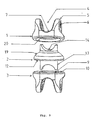
- the intermediate piece consists of a flat facet to allow anteroposterior and lateral rotations and translations and a spherical facet to allow anterior, posterior and lateral inclinations.
- the set allowing mobility in the three planes of space.
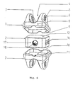
- the system according to the invention is composed of three elements, two inking pieces (1, 3), namely a thorny anchor piece upper (1), an intermediate piece (2) and a lower spinal anchor (3).
- all the elements are machined with biocompatible materials metal or not, and can adapt to all anatomical variants.
- the thorn anchors (1, 3) consist of a gutter-shaped body (4) with a groove (7) of cylindrical section, flared side walls (5) pierced with two orifices (6) aligned horizontally for gripping and fixing, using a metal device and whose ridges are rounded and blunt.
- the plane base (10) of the thorn anchors (1, 3) for the first two embodiments forms the interface with the flat surface (12) of the intermediate piece (2).
- the thorn anchors (1, 3) have, at their base, orifices (9) of different shapes or studs in which the intermediate piece (2) will be embedded by studs ( 13) or corresponding holes.
- the orifices (9) of the spiny anchoring pieces may have a quadrangular section for the fixed model ( fig.6 ), circular ( fig.3 ) to allow rotational movements, or oblong to allow rotational and lateral sliding movements.
- the thorn anchors (1, 3) have flats (8) or facets, anterior and posterior with a medial groove (11) facilitating alignment and assembly.
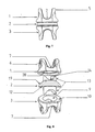
- the intermediate piece (2) intended to be interposed between the spinous anchoring pieces (1, 3) can be of different shapes and heights, provided or not with studs (13) or orifices .
- the intermediate piece (2) can be provided with cylindrical studs (13) which fit into the cylindrical orifices (9) of the thorn anchors (1, 3) to form a device mobile in rotation.
- the orifices (9) of the thorn anchors (1, 3) are oblong the device becomes mobile in rotation and lateral sliding.
- the ends of the studs (13) of the intermediate piece (2) comprise a recess (14) to avoid any conflict with the thorn.
- the intermediate piece (2) may be of parallelepipedal shape, with flat mounting facets (17) corresponding to the same-shaped orifices (10) of the thorn anchors (1, 3).
- the intermediate piece (2) can have variable mechanical characteristics in order to give a damping effect if necessary.
- the intermediate piece (2) is perforated horizontal transverse tunnels (15, 16) for fixing the system to spinous by a flexible ligamentary device and participate incidentally to the damping effect.
- the intermediate piece (2) may be provided with a threaded front hole (18) to facilitate gripping and assembly.
- the figure 9 illustrates a variant that will be called spherical system, according to which the cooperation between the intermediate piece (2) and the upper spinous inking piece (1) is thanks to a spherical support by cooperation of the bearing face (10) of the intermediate piece te the bearing face (20) of the inking piece (1) these two faces being spherical and in cooperation of shapes.
Claims (9)
- Interspinöses Stabilisierungssystem, dadurch gekennzeichnet, dass es aus zwei Elementen gebildet ist, die spinale Verankerungsteile (1, 3) genannt werden, und zwar aus einem oberen Verankerungsteil (1) und aus einem unteren Verankerungsteil (3), wobei jedes der Verankerungsteile aus einem rinnenförmigen Körper gebildet ist, sodass es an dem oberen beziehungsweise unteren Dornfortsatz befestigt werden kann, während das System ein drittes Element umfasst, das Zwischenstück (2) genannt wird und das zwischen den beiden spinalen Verankerungsteilen angeordnet und eingepasst ist, um das Auseinanderdrücken des interspinösen Raumes und die Beweglichkeit der Vorrichtung in den drei Raumebenen zu gewährleisten.
- System nach Anspruch 1, dadurch gekennzeichnet, dass die spinalen Verankerungsteile (1, 3) auf der Seite gegenüber dem Dornfortsatz Öffnungen (9) mit unterschiedlichen Formen oder Blöcke aufweisen, in die das Zwischenstück (2) über entsprechende Blöcke (13) oder Öffnungen passt, um die Beweglichkeit des Systems zu gewährleisten.
- System nach Anspruch 1 oder 2, dadurch gekennzeichnet, dass das Zwischenstück (2), das dafür bestimmt ist, zwischen den spinalen Verankerungsteilen (1, 3) angeordnet zu werden, unterschiedlich geformt und unterschiedlich hoch ist, mit Löchern oder Blöcken (13) versehen ist oder nicht versehen ist und aus verschiedenen Arten von Materialien hergestellt ist, um die Bewegungen zwischen den verschiedenen Elementen der Vorrichtung zu erleichtern.
- System nach einem der Ansprüche 1, 2 und 3, dadurch gekennzeichnet, dass das Zwischenstück (2) eine elliptische Form aufweist, die in ebenso geformte Öffnungen in den spinalen Verankerungsteilen (1, 3) passt, um eine Bewegung der Vorrichtung in mehreren Richtungen zu gewährleisten.
- System nach einem der vorhergehenden Ansprüche, dadurch gekennzeichnet, dass das Zwischenstück (2) mit zylindrischen Blöcken (13) versehen ist, die In die entsprechenden Öffnungen (9) der spinalen Verankerungsteile (1, 3) passen.
- System nach einem der vorhergehenden Ansprüche, dadurch gekennzeichnet, dass die spinalen Verankerungstelle (1, 3) mit zylindrischen Öffnungen (9) versehen sind, um die zylindrischen Blöcke (13) des Zwischenstücks (2) aufzunehmen und so eine drehbewegliche Vorrichtung zu bilden.
- System nach einem der Ansprüche 1 bis 5, dadurch gekennzeichnet, dass die spinalen Verankerungsteile (1, 3) mit länglichen Öffnungen (9) versehen sind, um die zylindrischen Blöcke (13) des Zwischenstücks (2) aufzunehmen und so eine Vorrichtung zu bilden, die drehbeweglich und seitlich verschiebbar ist.
- System nach einem der vorhergehenden Ansprüche, dadurch gekennzeichnet, dass das Zwischenstück (2) mit einer vorderen Öffnung (18) mit Gewinde versehen ist, um das Festhalten und die Montage zu erleichtern, und dass das Zwischenstück (2) mit Querkanälen (15, 16) versehen ist, damit das System mit einer flexiblen bandartigen Vorrichtung befestigt werden kann und mit denen zusätzlich zur stoßdämpfenden Wirkung beigetragen werden kann.
- System nach einem der vorhergehenden Ansprüche, dadurch gekennzeichnet, dass das Zwischenstück (2) aus einer ebenen Fläche gebildet ist, um Drehbewegungen und geradlinige Bewegungen anteroposterior und zur Seite zu ermöglichen, und aus einer kugelförmigen Fläche (19), um Neigungsbewegungen nach vorn, nach hinten und zur Seite zu ermöglichen. Mit dieser Anordnung ist eine Beweglichkeit in den drei Raumebenen möglich.
Applications Claiming Priority (1)
| Application Number | Priority Date | Filing Date | Title |
|---|---|---|---|
| PCT/FR2006/001589 WO2008003835A1 (fr) | 2006-07-03 | 2006-07-03 | Systeme de stabilisation inter-epineux |
Publications (2)
| Publication Number | Publication Date |
|---|---|
| EP2040632A1 EP2040632A1 (de) | 2009-04-01 |
| EP2040632B1 true EP2040632B1 (de) | 2010-05-05 |
Family
ID=37889976
Family Applications (1)
| Application Number | Title | Priority Date | Filing Date |
|---|---|---|---|
| EP06778770A Not-in-force EP2040632B1 (de) | 2006-07-03 | 2006-07-03 | Interspinöses stabilisierungssystem |
Country Status (9)
| Country | Link |
|---|---|
| US (1) | US20090254122A1 (de) |
| EP (1) | EP2040632B1 (de) |
| JP (1) | JP2009540997A (de) |
| AT (1) | ATE466533T1 (de) |
| AU (1) | AU2006345898A1 (de) |
| BR (1) | BRPI0621861A2 (de) |
| CA (1) | CA2656231A1 (de) |
| DE (1) | DE602006014222D1 (de) |
| WO (1) | WO2008003835A1 (de) |
Families Citing this family (14)
| Publication number | Priority date | Publication date | Assignee | Title |
|---|---|---|---|---|
| US9055981B2 (en) | 2004-10-25 | 2015-06-16 | Lanx, Inc. | Spinal implants and methods |
| US8241330B2 (en) | 2007-01-11 | 2012-08-14 | Lanx, Inc. | Spinous process implants and associated methods |
| US9265532B2 (en) | 2007-01-11 | 2016-02-23 | Lanx, Inc. | Interspinous implants and methods |
| US9381047B2 (en) | 2007-05-09 | 2016-07-05 | Ebi, Llc | Interspinous implant |
| US9173686B2 (en) * | 2007-05-09 | 2015-11-03 | Ebi, Llc | Interspinous implant |
| KR101003166B1 (ko) | 2008-05-13 | 2010-12-22 | 박춘근 | 추궁간 지지체 |
| WO2010114925A1 (en) | 2009-03-31 | 2010-10-07 | Lanx, Inc. | Spinous process implants and associated methods |
| US8388656B2 (en) | 2010-02-04 | 2013-03-05 | Ebi, Llc | Interspinous spacer with deployable members and related method |
| US9226779B2 (en) | 2011-02-02 | 2016-01-05 | Colorado State University Research Foundation | Pedicle screw assembly and dynamic spinal stabilization devices incorporating the pedicle screw assembly |
| FR2977139B1 (fr) | 2011-06-30 | 2014-08-22 | Ldr Medical | Implant inter-epineux et instrument d’implantation |
| US11812923B2 (en) | 2011-10-07 | 2023-11-14 | Alan Villavicencio | Spinal fixation device |
| ITPI20120022A1 (it) * | 2012-02-27 | 2013-08-28 | Marco Ceccarelli | Dispositivo distanziatore intervertebrale |
| US9554831B2 (en) | 2014-04-21 | 2017-01-31 | Warsaw Orthopedic, Inc. | Intervertebral spinal implant and method |
| US9622872B2 (en) | 2014-09-23 | 2017-04-18 | Warsaw Orthopedic, Inc. | Intervertebral spinal implant and method |
Family Cites Families (15)
| Publication number | Priority date | Publication date | Assignee | Title |
|---|---|---|---|---|
| FR2722980B1 (fr) * | 1994-07-26 | 1996-09-27 | Samani Jacques | Implant vertebral inter-epineux |
| US5860977A (en) * | 1997-01-02 | 1999-01-19 | Saint Francis Medical Technologies, Llc | Spine distraction implant and method |
| WO1999021501A1 (en) * | 1997-10-27 | 1999-05-06 | Saint Francis Medical Technologies, Llc | Spine distraction implant |
| FR2775183B1 (fr) * | 1998-02-20 | 2000-08-04 | Jean Taylor | Prothese inter-epineuse |
| ES2238290T3 (es) * | 1999-06-04 | 2005-09-01 | Sdgi Holdings, Inc. | Implante de disco artificial. |
| FR2811540B1 (fr) * | 2000-07-12 | 2003-04-25 | Spine Next Sa | Implant intervertebral amortissant |
| ITFI20030084A1 (it) * | 2003-03-28 | 2004-09-29 | Cousin Biotech S A S | Protesi vertebrale interlaminare |
| DE10330698B4 (de) * | 2003-07-08 | 2005-05-25 | Aesculap Ag & Co. Kg | Zwischenwirbelimplantat |
| US7011685B2 (en) * | 2003-11-07 | 2006-03-14 | Impliant Ltd. | Spinal prostheses |
| US7235103B2 (en) * | 2004-01-13 | 2007-06-26 | Rivin Evgeny I | Artificial intervertebral disc |
| US7763073B2 (en) * | 2004-03-09 | 2010-07-27 | Depuy Spine, Inc. | Posterior process dynamic spacer |
| US7883532B2 (en) * | 2005-04-25 | 2011-02-08 | Spineco, Inc. | Vertebral pars interarticularis clamp a new spine fixation device, instrumentation, and methodology |
| US20070005064A1 (en) * | 2005-06-27 | 2007-01-04 | Sdgi Holdings | Intervertebral prosthetic device for spinal stabilization and method of implanting same |
| US7691130B2 (en) * | 2006-01-27 | 2010-04-06 | Warsaw Orthopedic, Inc. | Spinal implants including a sensor and methods of use |
| US20070233096A1 (en) * | 2006-02-13 | 2007-10-04 | Javier Garcia-Bengochea | Dynamic inter-spinous device |
-
2006
- 2006-07-03 US US12/307,256 patent/US20090254122A1/en not_active Abandoned
- 2006-07-03 BR BRPI0621861-0A patent/BRPI0621861A2/pt not_active IP Right Cessation
- 2006-07-03 DE DE602006014222T patent/DE602006014222D1/de active Active
- 2006-07-03 AU AU2006345898A patent/AU2006345898A1/en not_active Abandoned
- 2006-07-03 CA CA002656231A patent/CA2656231A1/fr not_active Abandoned
- 2006-07-03 AT AT06778770T patent/ATE466533T1/de not_active IP Right Cessation
- 2006-07-03 EP EP06778770A patent/EP2040632B1/de not_active Not-in-force
- 2006-07-03 JP JP2009517307A patent/JP2009540997A/ja active Pending
- 2006-07-03 WO PCT/FR2006/001589 patent/WO2008003835A1/fr active Application Filing
Also Published As
| Publication number | Publication date |
|---|---|
| EP2040632A1 (de) | 2009-04-01 |
| ATE466533T1 (de) | 2010-05-15 |
| WO2008003835A1 (fr) | 2008-01-10 |
| DE602006014222D1 (de) | 2010-06-17 |
| CA2656231A1 (fr) | 2008-01-10 |
| JP2009540997A (ja) | 2009-11-26 |
| AU2006345898A1 (en) | 2008-01-10 |
| US20090254122A1 (en) | 2009-10-08 |
| BRPI0621861A2 (pt) | 2011-12-20 |
Similar Documents
| Publication | Publication Date | Title |
|---|---|---|
| EP2040632B1 (de) | Interspinöses stabilisierungssystem | |
| EP1330987B1 (de) | Zwischen Wirbeldornfortsätzen eingesetzte Wirbelsäulenimplantat | |
| EP1675513B1 (de) | Klingen-zwischenstütze | |
| EP1909664B1 (de) | Rotierendes interspinöses gerät | |
| CA1262322A (fr) | Dispositif pour l'etaiement du rachis | |
| CA2466661C (fr) | Prothese d'articulation vertebrale posterieure | |
| EP2164412B1 (de) | Zwischenwirbelimplantat | |
| EP0689401B1 (de) | Universaler stabilisator für die wirbelsäule | |
| FR2727003A1 (fr) | Dispositif de stabilisation anterieure du rachis lombo-sacre | |
| FR2858546A1 (fr) | Prothese de disque intervertebral | |
| FR2799948A1 (fr) | Barre de liaison pour l'ancrage d'une prothese inter epineuse | |
| CA2541002A1 (fr) | Implant intervertebral | |
| EP2277460A1 (de) | Chirurgische Instrumentierung zur Vorbereitung des Einsetzens einer Knieprothese | |
| FR2884135A1 (fr) | Implant intervertebral pour l'articulation lombo-sacree | |
| WO2001001874A1 (fr) | Plaque d'osteosynthese vertebrale et systeme d'osteosynthese | |
| FR2833151A1 (fr) | Implant d'ancrage osseux a tete polyaxiale | |
| FR2781359A1 (fr) | Materiel d'osteosynthese rachidienne | |
| FR2880256A1 (fr) | Systeme d'osteosynthese vertebrale | |
| FR3015221A1 (fr) | Systeme d'implant intravertebral expansible avec fixation pediculaire posterieure | |
| WO2009133539A1 (fr) | Crochet pour dispositif d'ostéosynthèse vertébrale et dispositif le comprenant | |
| EP2459089B1 (de) | Zusatzscheiben-wirbelkörperstabilisierungsvorrichtung | |
| FR2861285A1 (fr) | Support inter-lamaire | |
| EP1278468B1 (de) | Querverbinder für wirbelsäulenosteosynthese | |
| FR2882513A1 (fr) | Systeme de stabilisation inter-epineux | |
| EP1795135B1 (de) | Einrichtung zur lateralen dynamischen Stabilisierung der Wirbelsäule |
Legal Events
| Date | Code | Title | Description |
|---|---|---|---|
| PUAI | Public reference made under article 153(3) epc to a published international application that has entered the european phase |
Free format text: ORIGINAL CODE: 0009012 |
|
| 17P | Request for examination filed |
Effective date: 20090123 |
|
| AK | Designated contracting states |
Kind code of ref document: A1 Designated state(s): AT BE BG CH CY CZ DE DK EE ES FI FR GB GR HU IE IS IT LI LT LU LV MC NL PL PT RO SE SI SK TR |
|
| AX | Request for extension of the european patent |
Extension state: AL BA HR MK RS |
|
| 17Q | First examination report despatched |
Effective date: 20090703 |
|
| GRAP | Despatch of communication of intention to grant a patent |
Free format text: ORIGINAL CODE: EPIDOSNIGR1 |
|
| GRAS | Grant fee paid |
Free format text: ORIGINAL CODE: EPIDOSNIGR3 |
|
| GRAA | (expected) grant |
Free format text: ORIGINAL CODE: 0009210 |
|
| AK | Designated contracting states |
Kind code of ref document: B1 Designated state(s): AT BE BG CH CY CZ DE DK EE ES FI FR GB GR HU IE IS IT LI LT LU LV MC NL PL PT RO SE SI SK TR |
|
| REG | Reference to a national code |
Ref country code: GB Ref legal event code: FG4D Free format text: NOT ENGLISH |
|
| REG | Reference to a national code |
Ref country code: CH Ref legal event code: EP |
|
| REG | Reference to a national code |
Ref country code: IE Ref legal event code: FG4D Free format text: LANGUAGE OF EP DOCUMENT: FRENCH |
|
| REF | Corresponds to: |
Ref document number: 602006014222 Country of ref document: DE Date of ref document: 20100617 Kind code of ref document: P |
|
| REG | Reference to a national code |
Ref country code: CH Ref legal event code: NV Representative=s name: AMMANN PATENTANWAELTE AG BERN |
|
| REG | Reference to a national code |
Ref country code: NL Ref legal event code: VDEP Effective date: 20100505 |
|
| LTIE | Lt: invalidation of european patent or patent extension |
Effective date: 20100505 |
|
| PG25 | Lapsed in a contracting state [announced via postgrant information from national office to epo] |
Ref country code: SE Free format text: LAPSE BECAUSE OF FAILURE TO SUBMIT A TRANSLATION OF THE DESCRIPTION OR TO PAY THE FEE WITHIN THE PRESCRIBED TIME-LIMIT Effective date: 20100505 Ref country code: NL Free format text: LAPSE BECAUSE OF FAILURE TO SUBMIT A TRANSLATION OF THE DESCRIPTION OR TO PAY THE FEE WITHIN THE PRESCRIBED TIME-LIMIT Effective date: 20100505 Ref country code: ES Free format text: LAPSE BECAUSE OF FAILURE TO SUBMIT A TRANSLATION OF THE DESCRIPTION OR TO PAY THE FEE WITHIN THE PRESCRIBED TIME-LIMIT Effective date: 20100816 Ref country code: LT Free format text: LAPSE BECAUSE OF FAILURE TO SUBMIT A TRANSLATION OF THE DESCRIPTION OR TO PAY THE FEE WITHIN THE PRESCRIBED TIME-LIMIT Effective date: 20100505 |
|
| PG25 | Lapsed in a contracting state [announced via postgrant information from national office to epo] |
Ref country code: LV Free format text: LAPSE BECAUSE OF FAILURE TO SUBMIT A TRANSLATION OF THE DESCRIPTION OR TO PAY THE FEE WITHIN THE PRESCRIBED TIME-LIMIT Effective date: 20100505 Ref country code: AT Free format text: LAPSE BECAUSE OF FAILURE TO SUBMIT A TRANSLATION OF THE DESCRIPTION OR TO PAY THE FEE WITHIN THE PRESCRIBED TIME-LIMIT Effective date: 20100505 Ref country code: SI Free format text: LAPSE BECAUSE OF FAILURE TO SUBMIT A TRANSLATION OF THE DESCRIPTION OR TO PAY THE FEE WITHIN THE PRESCRIBED TIME-LIMIT Effective date: 20100505 Ref country code: FI Free format text: LAPSE BECAUSE OF FAILURE TO SUBMIT A TRANSLATION OF THE DESCRIPTION OR TO PAY THE FEE WITHIN THE PRESCRIBED TIME-LIMIT Effective date: 20100505 Ref country code: IS Free format text: LAPSE BECAUSE OF FAILURE TO SUBMIT A TRANSLATION OF THE DESCRIPTION OR TO PAY THE FEE WITHIN THE PRESCRIBED TIME-LIMIT Effective date: 20100905 |
|
| REG | Reference to a national code |
Ref country code: IE Ref legal event code: FD4D |
|
| PG25 | Lapsed in a contracting state [announced via postgrant information from national office to epo] |
Ref country code: CY Free format text: LAPSE BECAUSE OF FAILURE TO SUBMIT A TRANSLATION OF THE DESCRIPTION OR TO PAY THE FEE WITHIN THE PRESCRIBED TIME-LIMIT Effective date: 20100609 Ref country code: GR Free format text: LAPSE BECAUSE OF FAILURE TO SUBMIT A TRANSLATION OF THE DESCRIPTION OR TO PAY THE FEE WITHIN THE PRESCRIBED TIME-LIMIT Effective date: 20100806 Ref country code: PL Free format text: LAPSE BECAUSE OF FAILURE TO SUBMIT A TRANSLATION OF THE DESCRIPTION OR TO PAY THE FEE WITHIN THE PRESCRIBED TIME-LIMIT Effective date: 20100505 |
|
| PG25 | Lapsed in a contracting state [announced via postgrant information from national office to epo] |
Ref country code: IE Free format text: LAPSE BECAUSE OF FAILURE TO SUBMIT A TRANSLATION OF THE DESCRIPTION OR TO PAY THE FEE WITHIN THE PRESCRIBED TIME-LIMIT Effective date: 20100505 Ref country code: PT Free format text: LAPSE BECAUSE OF FAILURE TO SUBMIT A TRANSLATION OF THE DESCRIPTION OR TO PAY THE FEE WITHIN THE PRESCRIBED TIME-LIMIT Effective date: 20100906 Ref country code: DK Free format text: LAPSE BECAUSE OF FAILURE TO SUBMIT A TRANSLATION OF THE DESCRIPTION OR TO PAY THE FEE WITHIN THE PRESCRIBED TIME-LIMIT Effective date: 20100505 Ref country code: EE Free format text: LAPSE BECAUSE OF FAILURE TO SUBMIT A TRANSLATION OF THE DESCRIPTION OR TO PAY THE FEE WITHIN THE PRESCRIBED TIME-LIMIT Effective date: 20100505 |
|
| PG25 | Lapsed in a contracting state [announced via postgrant information from national office to epo] |
Ref country code: RO Free format text: LAPSE BECAUSE OF FAILURE TO SUBMIT A TRANSLATION OF THE DESCRIPTION OR TO PAY THE FEE WITHIN THE PRESCRIBED TIME-LIMIT Effective date: 20100505 Ref country code: CZ Free format text: LAPSE BECAUSE OF FAILURE TO SUBMIT A TRANSLATION OF THE DESCRIPTION OR TO PAY THE FEE WITHIN THE PRESCRIBED TIME-LIMIT Effective date: 20100505 Ref country code: SK Free format text: LAPSE BECAUSE OF FAILURE TO SUBMIT A TRANSLATION OF THE DESCRIPTION OR TO PAY THE FEE WITHIN THE PRESCRIBED TIME-LIMIT Effective date: 20100505 Ref country code: MC Free format text: LAPSE BECAUSE OF NON-PAYMENT OF DUE FEES Effective date: 20100731 |
|
| PLBE | No opposition filed within time limit |
Free format text: ORIGINAL CODE: 0009261 |
|
| STAA | Information on the status of an ep patent application or granted ep patent |
Free format text: STATUS: NO OPPOSITION FILED WITHIN TIME LIMIT |
|
| PG25 | Lapsed in a contracting state [announced via postgrant information from national office to epo] |
Ref country code: IT Free format text: LAPSE BECAUSE OF FAILURE TO SUBMIT A TRANSLATION OF THE DESCRIPTION OR TO PAY THE FEE WITHIN THE PRESCRIBED TIME-LIMIT Effective date: 20100505 |
|
| 26N | No opposition filed |
Effective date: 20110208 |
|
| REG | Reference to a national code |
Ref country code: DE Ref legal event code: R097 Ref document number: 602006014222 Country of ref document: DE Effective date: 20110207 |
|
| PG25 | Lapsed in a contracting state [announced via postgrant information from national office to epo] |
Ref country code: BG Free format text: LAPSE BECAUSE OF FAILURE TO SUBMIT A TRANSLATION OF THE DESCRIPTION OR TO PAY THE FEE WITHIN THE PRESCRIBED TIME-LIMIT Effective date: 20100505 Ref country code: LU Free format text: LAPSE BECAUSE OF NON-PAYMENT OF DUE FEES Effective date: 20100703 Ref country code: HU Free format text: LAPSE BECAUSE OF FAILURE TO SUBMIT A TRANSLATION OF THE DESCRIPTION OR TO PAY THE FEE WITHIN THE PRESCRIBED TIME-LIMIT Effective date: 20101106 |
|
| PG25 | Lapsed in a contracting state [announced via postgrant information from national office to epo] |
Ref country code: TR Free format text: LAPSE BECAUSE OF FAILURE TO SUBMIT A TRANSLATION OF THE DESCRIPTION OR TO PAY THE FEE WITHIN THE PRESCRIBED TIME-LIMIT Effective date: 20100505 |
|
| PG25 | Lapsed in a contracting state [announced via postgrant information from national office to epo] |
Ref country code: BG Free format text: LAPSE BECAUSE OF FAILURE TO SUBMIT A TRANSLATION OF THE DESCRIPTION OR TO PAY THE FEE WITHIN THE PRESCRIBED TIME-LIMIT Effective date: 20100805 |
|
| PGFP | Annual fee paid to national office [announced via postgrant information from national office to epo] |
Ref country code: CH Payment date: 20130726 Year of fee payment: 8 Ref country code: DE Payment date: 20130730 Year of fee payment: 8 |
|
| PGFP | Annual fee paid to national office [announced via postgrant information from national office to epo] |
Ref country code: GB Payment date: 20130725 Year of fee payment: 8 |
|
| PGFP | Annual fee paid to national office [announced via postgrant information from national office to epo] |
Ref country code: BE Payment date: 20130830 Year of fee payment: 8 |
|
| REG | Reference to a national code |
Ref country code: DE Ref legal event code: R119 Ref document number: 602006014222 Country of ref document: DE |
|
| REG | Reference to a national code |
Ref country code: CH Ref legal event code: PL |
|
| GBPC | Gb: european patent ceased through non-payment of renewal fee |
Effective date: 20140703 |
|
| PG25 | Lapsed in a contracting state [announced via postgrant information from national office to epo] |
Ref country code: DE Free format text: LAPSE BECAUSE OF NON-PAYMENT OF DUE FEES Effective date: 20150203 Ref country code: LI Free format text: LAPSE BECAUSE OF NON-PAYMENT OF DUE FEES Effective date: 20140731 Ref country code: CH Free format text: LAPSE BECAUSE OF NON-PAYMENT OF DUE FEES Effective date: 20140731 |
|
| REG | Reference to a national code |
Ref country code: DE Ref legal event code: R119 Ref document number: 602006014222 Country of ref document: DE Effective date: 20150203 |
|
| PG25 | Lapsed in a contracting state [announced via postgrant information from national office to epo] |
Ref country code: GB Free format text: LAPSE BECAUSE OF NON-PAYMENT OF DUE FEES Effective date: 20140703 |
|
| REG | Reference to a national code |
Ref country code: FR Ref legal event code: PLFP Year of fee payment: 10 |
|
| REG | Reference to a national code |
Ref country code: FR Ref legal event code: PLFP Year of fee payment: 11 |
|
| REG | Reference to a national code |
Ref country code: FR Ref legal event code: PLFP Year of fee payment: 12 |
|
| PG25 | Lapsed in a contracting state [announced via postgrant information from national office to epo] |
Ref country code: BE Free format text: LAPSE BECAUSE OF NON-PAYMENT OF DUE FEES Effective date: 20140731 |
|
| PGFP | Annual fee paid to national office [announced via postgrant information from national office to epo] |
Ref country code: FR Payment date: 20170728 Year of fee payment: 12 |
|
| PG25 | Lapsed in a contracting state [announced via postgrant information from national office to epo] |
Ref country code: FR Free format text: LAPSE BECAUSE OF NON-PAYMENT OF DUE FEES Effective date: 20180731 |