EP2040044B1 - Procédé de fabrication d'un carter de compteur à détection magnétique et carter ainsi obtenu - Google Patents
Procédé de fabrication d'un carter de compteur à détection magnétique et carter ainsi obtenu Download PDFInfo
- Publication number
- EP2040044B1 EP2040044B1 EP08164182.1A EP08164182A EP2040044B1 EP 2040044 B1 EP2040044 B1 EP 2040044B1 EP 08164182 A EP08164182 A EP 08164182A EP 2040044 B1 EP2040044 B1 EP 2040044B1
- Authority
- EP
- European Patent Office
- Prior art keywords
- piston
- housing
- wall
- meter
- magnetic
- Prior art date
- Legal status (The legal status is an assumption and is not a legal conclusion. Google has not performed a legal analysis and makes no representation as to the accuracy of the status listed.)
- Active
Links
Images

Classifications
-
- G—PHYSICS
- G01—MEASURING; TESTING
- G01F—MEASURING VOLUME, VOLUME FLOW, MASS FLOW OR LIQUID LEVEL; METERING BY VOLUME
- G01F1/00—Measuring the volume flow or mass flow of fluid or fluent solid material wherein the fluid passes through a meter in a continuous flow
- G01F1/05—Measuring the volume flow or mass flow of fluid or fluent solid material wherein the fluid passes through a meter in a continuous flow by using mechanical effects
- G01F1/10—Measuring the volume flow or mass flow of fluid or fluent solid material wherein the fluid passes through a meter in a continuous flow by using mechanical effects using rotating vanes with axial admission
- G01F1/115—Measuring the volume flow or mass flow of fluid or fluent solid material wherein the fluid passes through a meter in a continuous flow by using mechanical effects using rotating vanes with axial admission with magnetic or electromagnetic coupling to the indicating device
- G01F1/1155—Measuring the volume flow or mass flow of fluid or fluent solid material wherein the fluid passes through a meter in a continuous flow by using mechanical effects using rotating vanes with axial admission with magnetic or electromagnetic coupling to the indicating device with magnetic coupling only in a mechanical transmission path
-
- B—PERFORMING OPERATIONS; TRANSPORTING
- B29—WORKING OF PLASTICS; WORKING OF SUBSTANCES IN A PLASTIC STATE IN GENERAL
- B29C—SHAPING OR JOINING OF PLASTICS; SHAPING OF MATERIAL IN A PLASTIC STATE, NOT OTHERWISE PROVIDED FOR; AFTER-TREATMENT OF THE SHAPED PRODUCTS, e.g. REPAIRING
- B29C45/00—Injection moulding, i.e. forcing the required volume of moulding material through a nozzle into a closed mould; Apparatus therefor
- B29C45/17—Component parts, details or accessories; Auxiliary operations
- B29C45/46—Means for plasticising or homogenising the moulding material or forcing it into the mould
- B29C45/56—Means for plasticising or homogenising the moulding material or forcing it into the mould using mould parts movable during or after injection, e.g. injection-compression moulding
- B29C45/561—Injection-compression moulding
-
- G—PHYSICS
- G01—MEASURING; TESTING
- G01F—MEASURING VOLUME, VOLUME FLOW, MASS FLOW OR LIQUID LEVEL; METERING BY VOLUME
- G01F15/00—Details of, or accessories for, apparatus of groups G01F1/00 - G01F13/00 insofar as such details or appliances are not adapted to particular types of such apparatus
- G01F15/14—Casings, e.g. of special material
-
- B—PERFORMING OPERATIONS; TRANSPORTING
- B29—WORKING OF PLASTICS; WORKING OF SUBSTANCES IN A PLASTIC STATE IN GENERAL
- B29C—SHAPING OR JOINING OF PLASTICS; SHAPING OF MATERIAL IN A PLASTIC STATE, NOT OTHERWISE PROVIDED FOR; AFTER-TREATMENT OF THE SHAPED PRODUCTS, e.g. REPAIRING
- B29C45/00—Injection moulding, i.e. forcing the required volume of moulding material through a nozzle into a closed mould; Apparatus therefor
- B29C45/0025—Preventing defects on the moulded article, e.g. weld lines, shrinkage marks
-
- B—PERFORMING OPERATIONS; TRANSPORTING
- B29—WORKING OF PLASTICS; WORKING OF SUBSTANCES IN A PLASTIC STATE IN GENERAL
- B29C—SHAPING OR JOINING OF PLASTICS; SHAPING OF MATERIAL IN A PLASTIC STATE, NOT OTHERWISE PROVIDED FOR; AFTER-TREATMENT OF THE SHAPED PRODUCTS, e.g. REPAIRING
- B29C45/00—Injection moulding, i.e. forcing the required volume of moulding material through a nozzle into a closed mould; Apparatus therefor
- B29C45/17—Component parts, details or accessories; Auxiliary operations
- B29C45/26—Moulds
- B29C45/261—Moulds having tubular mould cavities
Definitions
- the invention relates to a method of manufacturing a magnetic detection meter housing and a housing thus obtained.
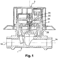
- the figure 1 represents such a known magnetic detection counter for measuring a volume or a flow rate of fluid, in particular water.
- This counter comprises a trough-shaped tank 1 and provided with an inlet pipe section 1A and an outlet pipe section 1B.
- the inlet conduit section 1A is intended to be connected to a water supply pipe and the outlet pipe section 1B to a water discharge pipe.
- a measuring chamber 2 here turbine 2A, contained in a housing 1 B.
- the axis of the turbine is provided with a first magnetic element 2C.
- a totalizer 3 which comprises a display and a meter connected to a magnetic sensor 3A for transmitting the number of revolutions of the turbine to the meter.
- this sensor 3A is disposed facing the magnetic element 2C of the measuring chamber and is separated from this element 2C by an upper wall of the housing 2B which is thinned to the right of this magnetic arrangement, to allow good transmission of the magnetic field between the element 2C and the sensor 3A.
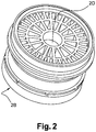
- the figure 2 represents such a housing 2B measuring chamber.
- the upper wall of this casing therefore has a thinned central wall portion 2D, hereinafter transmission wall, against which is housed the magnetic sensor 2C of the totalizer and under which is disposed the magnetic element 2C connected to the axis of the turbine 2A.
- this plastic housing 2B for example aromatic polyamide
- this plastic housing 2B for example aromatic polyamide
- the object of the invention is to propose a method of manufacturing such a housing which makes it possible to obtain a transmission wall of reduced thickness, in order to ensure optimum magnetic field transmission between the measuring chamber and the totalizer. while providing a mechanically resistant housing to the hydraulic operating forces of the meter.
- the invention proposes a method of molding by injection of a housing, made of plastic material, a measurement chamber of a magnetic detection counter, comprising a so-called transmission wall, intended to be arranged between a magnetic element contained by said measuring chamber and a magnetic sensor located in a totalizer, said transmission wall being molded by means of a piston translatable perpendicularly to the plane of the molding cavity of this wall.
- the piston which can be heated or not, is pushed immediately after the injection of resin in the solidified half state or in the solidified state.
- the invention solves this problem by proposing a method of molding by injection of a plastic housing, a measuring chamber of a magnetic detection counter, which ensures a perfect mechanical quality of the molded material while using a piston of this type for producing a thin transmission wall improving the transmission of the magnetic signals between the measuring chamber and the totalizer of a meter.
- the invention proposes a method of molding by injection of a housing, made of plastic material, a measurement chamber of a magnetic detection counter, comprising a so-called transmission wall, intended to be arranged between a magnetic element contained by said measuring chamber and a magnetic sensor located in a totalizer, said transmission wall being molded by means of a translatable piston perpendicular to the plane of the molding cavity of said wall, characterized in that said piston is translated into the molding cavity during the injection of the plastic material into said molding cavity. The piston is translated as soon as the plastic passes to the right of the piston.
- the piston is thus translated into a molding cavity which still contains air, which makes it possible to induce no stress on the plastic material.
- This molding process allows, without any machining, the realization of a transmission wall of a particularly reduced thickness.
- the thickness of the transmission wall is completely controlled by displacement of the piston.
- the piston can be translated, when there remains in said mold cavity a volume of air equal to or greater than the volume of the piston in said cavity, at the end of the stroke.
- the injection is performed by means of a lateral injection inlet to the housing mold cavity.
- the injection is preferably located outside the transmission wall in a zone favoring the filling of the cavity with the plastic material.
- the invention also relates to a housing of a measuring chamber of a magnetic detection counter obtained by means of the method as specified above, characterized in that said transmission wall has a thickness of between 0.5 and 1. , 5 mm.
- said transmission wall has a thickness of about 1.2 mm.
- such a thickness of the transmission wall generates an air gap between the totalizer sensor 3A and the magnetic element 2C of the particularly low measuring chamber and makes it possible to avoid a decoupling phenomenon due to a desynchronization of these two elements.
- DE19923932 relates to a water meter with mechanism and the indicator of operation (dry) in a tube.
- the inlet port for the water meter as well as fluid channels are manufactured in the frame of the measuring chamber cover.
- the measuring chamber cover is made from fiber reinforced plastic using a metal injection molding process.
- EP1405708 method of manufacturing a tube of an injector comprises injecting the molten resin into the cavity of a metal mold; injecting the molten resin into a hollow cylindrical portion; and feeding the resin within the cylindrical hollow portion into the cavity by a push rod installed in the cylindrical hollow portion when the molten resin is molten.
- a measuring device for measuring a flow rate of a liquid
- the apparatus comprising a passage through which the liquid can flow, a rotatable member mounted to extend at least partially in said passage so as to rotate by the liquid flowing through the passage, electromagnetic detection means for detecting the rotation of the rotary member, determining means for determining a flow of flow liquid through the passage on the basis of the rotation and the means for determining display detected to display information associated with said determined rate.
- DE29806191 relates to a flow meter for fluid media, in particular liquids, allowing it to pass through a measuring chamber of a rotor in rotation, by magnetic coupling with a rotary joint meter, where the magnetic coupling of the two mutually coaxial, separated by a less a non-magnetic partition on the other, each.
- FR2878777 method for manufacturing a thin-walled section in an injection-molded plastic part comprises providing a mold having a first mold half, a second mold half, and a slide, which define a mold cavity; mold.
- the molding is at the end of the process and the molding cavity is filled with plastic material, for example polyphthalamide, forming a casing 2B.
- plastic material for example polyphthalamide
- the molding is done by injection produced by means of a lateral injection inlet E to the molding cavity of the casing 2B.
- This input E is located near the molding cavity of the upper wall of the housing.
- the 2D transmission wall of the housing is molded by means of a translatable piston P perpendicular to the plane of the molding cavity of this 2D wall.
- the plastic is injected under pressure from a reservoir R to the injection inlet E and fills the molding cavity of the casing.
- the piston P is then in its rest position not protruding into the molding cavity and, when the plastic material reaches the right of the piston, the latter is translated to the molding cavity, then is stopped in the final molding position, in order to form a transmission wall with a thickness of between 0.5 and 1.5 mm, and preferably about 1.2 mm.
- the piston is translated, when there remains in said mold cavity a volume of air equal to or greater than the volume of the piston in said cavity, at the end of the stroke.
- the translation of the piston can be started between 1/3 and 9/10 of the overall injection time.
- the piston is moved back to allow demolding and separation of the mold parts.
Landscapes
- Physics & Mathematics (AREA)
- Fluid Mechanics (AREA)
- General Physics & Mathematics (AREA)
- Electromagnetism (AREA)
- Engineering & Computer Science (AREA)
- Manufacturing & Machinery (AREA)
- Mechanical Engineering (AREA)
- Injection Moulding Of Plastics Or The Like (AREA)
- Measuring Volume Flow (AREA)
Description
- L'invention concerne un procédé de fabrication d'un carter de compteur à détection magnétique et un carter ainsi obtenu.
- La
figure 1 représente un tel compteur connu à détection magnétique destiné à la mesure d'un volume ou d'un débit de fluide, en particulier d'eau. - Ce compteur comporte une bâche 1 en forme d'auge et pourvue d'un tronçon de conduit d'entrée 1A et d'un tronçon de conduit de sortie 1B. Le tronçon de conduit d'entrée 1A est destiné à être connecté à une canalisation d'arrivée d'eau et le tronçon de conduit de sortie 1B à une canalisation d'évacuation d'eau.
- Sur cette bâche, est montée une chambre de mesure 2, ici à turbine 2A, contenue dans un carter 1 B. L'axe de la turbine est pourvu d'un premier élément magnétique 2C.
- Sur cette chambre de mesure, est disposé un totalisateur 3 qui comporte un afficheur et un compteur connecté à un capteur magnétique 3A destiné à transmettre le nombre de tours de la turbine au compteur.
- Pour ce faire, ce capteur 3A est disposé face à l'élément magnétique 2C de la chambre de mesure et est séparé de cet élément 2C par une paroi supérieure du carter 2B qui est amincie au droit de cet agencement magnétique, afin de permettre une bonne transmission du champ magnétique entre l'élément 2C et le capteur 3A.
- En effet, une épaisseur trop importante de cette paroi amincie entraîne un entrefer important entre le capteur 3A du totalisateur et l'élément magnétique 2C de la chambre de mesure, formés d'aimants, et nécessite des aimants plus puissants, donc plus chers et surtout plus vulnérables aux tentatives de fraudes par utilisation d'un aimant externe au compteur.
- La
figure 2 représente un tel carter 2B de chambre de mesure. La paroi supérieure de ce carter présente donc une partie de paroi centrale amincie 2D, dite ci-après paroi de transmission, contre laquelle est logé le capteur magnétique 2C du totalisateur et sous laquelle est disposé l'élément magnétique 2C lié à l'axe de la turbine 2A. - Il est connu de réaliser ce carter 2B en matière plastique, par exemple en polyamide aromatique, par moulage et injection au niveau au centre de la paroi supérieure du carter ainsi moulé, afin d'éviter la formation de lignes de soudure qui seraient préjudiciables à l'étanchéité et à la bonne tenue mécanique du carter soumis à des efforts hydraulique lors du fonctionnement du compteur. Par un tel procédé de moulage, il est possible d'obtenir une paroi de transmission 2D d'une épaisseur d'environ 2,5 mm. Un usinage postérieur peut également permettre de réduire l'épaisseur de la paroi de transmission.
- Le but de l'invention est de proposer un procédé de fabrication d'un tel carter qui permette d'obtenir une paroi de transmission d'épaisseur réduite, afin d'assurer une transmission du champ magnétique optimale entre la chambre de mesure et le totalisateur, tout en fournissant un carter résistant mécaniquement aux efforts hydrauliques de fonctionnement du compteur.
- Pour ce faire, l'invention propose un procédé de moulage par injection d'un carter, en matière plastique, d'une chambre de mesure d'un compteur à détection magnétique, comportant une paroi dite de transmission, destinée à être disposée entre un élément magnétique contenu par ladite chambre de mesure et un capteur magnétique situé dans un totalisateur, ladite paroi de transmission étant moulée au moyen d'un piston translatable perpendiculairement au plan de la cavité de moulage de cette paroi.
- Il est connu du document de brevet
JP 61-125825 - Selon ce procédé connu, le piston, qui peut être chauffé ou non, est poussé immédiatement après l'injection de résine à l'état demi solidifié ou à l'état solidifié.
- Un tel procédé induit des contraintes sur la matière moulée, par compactage et donc dégradation de la matière plastique, et il en résulte une modification des caractéristiques mécaniques initiales de la matière injectée, qui sont problématiques dans le cas de la réalisation d'une paroi de transmission de carter de chambre de mesure de compteur, qui doit, outre ses propriétés de transmission, résister à des pressions hydrodynamiques.
- L'invention résout ce problème en proposant un procédé de moulage par injection d'un carter, en matière plastique, d'une chambre de mesure d'un compteur à détection magnétique, qui assure une qualité mécanique parfaite de la matière moulée tout en utilisant un piston de ce type pour réaliser une paroi fine de transmission améliorant la transmission des signaux magnétiques entre la chambre de mesure et la totalisateur d'un compteur.
- Pour ce faire, l'invention propose un procédé de moulage par injection d'un carter, en matière plastique, d'une chambre de mesure d'un compteur à détection magnétique, comportant une paroi dite de transmission, destinée à être disposée entre un élément magnétique contenu par ladite chambre de mesure et un capteur magnétique situé dans un totalisateur, ladite paroi de transmission étant moulée au moyen d'un piston translatable perpendiculairement au plan de la cavité de moulage de cette paroi, procédé caractérisé en ce que ledit piston est translaté dans la cavité de moulage au cours de l'injection de la matière plastique dans ladite cavité de moulage. Le piston est translaté dès passage de la matière plastique au droit du piston.
- Le piston est donc translaté dans une cavité de moulage qui contient encore de l'air ce qui permet de n'induire aucune contrainte sur la matière plastique.
- Ce procédé de moulage permet, sans aucun usinage, la réalisation d'une paroi de transmission d'une épaisseur particulièrement réduite.
- De plus, grâce à ce procédé, l'épaisseur de la paroi de transmission est totalement maîtrisée par déplacement du piston.
- Le piston peut être translaté, lorsqu'il reste dans ladite cavité de moulage un volume d'air égal ou supérieur au volume du piston dans la dite cavité, en fin de course.
- Avantageusement, l'injection est réalisée au moyen d'une entrée d'injection latérale à la cavité de moulage du carter.
- L'injection est, de préférence, située hors de la paroi de transmission dans une zone favorisant le remplissage de la cavité par la matière plastique.
- L'invention concerne également un carter d'une chambre de mesure d'un compteur à détection magnétique obtenu au moyen du procédé tel que précisé ci-dessus, caractérisé en ce que ladite paroi de transmission a une épaisseur comprise entre 0,5 et 1,5 mm.
- Avantageusement, ladite paroi de transmission a une épaisseur d'environ 1,2 mm.
- En effet, une telle épaisseur de la paroi de transmission génère un entrefer entre le capteur 3A du totalisateur et l'élément magnétique 2C de la chambre de mesure particulièrement faible et permet d'éviter un phénomène de découplage due à une désynchronisation de ces deux éléments magnétiques formés d'un aimant, en particulier à fort débit et haute vitesse du fluide, en particulier de l'eau dans le compteur.
-
DE19923932 concerne un compteur d'eau avec mécanisme et l'indicateur de fonctionnement (à sec) dans une chambre à air. L'orifice d'entrée pour le compteur d'eau ainsi que des canaux de fluide sont fabriqués dans le cadre du couvercle de la chambre de mesure. Le couvercle de la chambre de mesure est fabriqué à partir de plastique renforcé de fibre au moyen d'un procédé de moulage par injection de métal. -
EP1405708 concerne un procédé de fabrication d'un tube d'un injecteur comprend l'injection de la résine fondue dans la cavité d'un moule métallique; injecter la résine fondue dans une partie cylindrique creuse; et de gavage de la résine à l'intérieur de la partie creuse cylindrique dans la cavité par une tige de poussée installé dans la partie creuse cylindrique lorsque vient la résine fondue à l'état semi-fondu. -
WO 02/01164 -
DE29806191 concerne un débitmètre pour milieux fluides, en particulier des liquides, permettant son passage dans une chambre de mesure d'un rotor en rotation, par un couplage magnétique avec un compteur à joint tournant, où le couplage magnétique des deux mutuellement coaxiaux, séparés par au moins une cloison non-magnétique de l'autre, chacune. -
FR2878777 - L'invention est décrite ci-après plus en détail à l'aide de figures ne représentant qu'un mode de réalisation préféré de l'invention.
- Les
figures 1 et2 ont été déjà été évoquées et illustrent, vu en coupe, un compteur et, vu en perspective, un carter de chambre de mesure. - Les
figures 3 et 4 sont des vues en coupe d'un appareillage de moulage pour la fabrication d'un carter conforme à l'invention. - Sur ces dernières figures, le moulage est en fin de processus et la cavité de moulage est remplie de matière plastique, par exemple du polyphtalamide, formant un carter 2B.
- Le moulage se fait par injection réalisée au moyen d'une entrée d'injection E latérale à la cavité de moulage du carter 2B. Cette entrée E est située à proximité de la cavité de moulage de la paroi supérieure du carter.
- La paroi de transmission 2D du carter est moulée au moyen d'un piston P translatable perpendiculairement au plan de la cavité de moulage de cette paroi 2D.
- Lors d'une opération de moulage, la matière plastique est injectée sous pression d'un réservoir R vers l'entrée E d'injection et remplit la cavité de moulage du carter. Le piston P est alors dans sa position de repos ne faisant pas saillie dans la cavité de moulage et, lorsque la matière plastique arrive au droit du piston, ce dernier est translaté vers la cavité de moulage, puis est arrêté en position finale de moulage, afin de former une paroi de transmission d'une épaisseur comprise entre 0,5 et 1,5 mm, et de préférence d'environ 1,2 mm.
- Le piston est translaté, lorsqu'il reste dans ladite cavité de moulage un volume d'air égal ou supérieur au volume du piston dans la dite cavité, en fin de course.
- Selon le positionnement du piston P par rapport à l'entrée d'injection E, la translation du piston peut être commencée entre 1/3 et 9/10 du temps global d'injection.
- Lors de l'opération de démoulage conséquente, le piston est reculé afin de permettre le démoulage et la séparation des parties de moule.
Claims (5)
- Procédé de moulage par injection d'un carter (2B), en matière plastique, d'une chambre de mesure (2) d'un compteur à détection magnétique, comportant une paroi dite de transmission (2D), destinée à être disposée entre un élément magnétique (2C) contenu par ladite chambre de mesure et un capteur magnétique (3A) situé dans un totalisateur (3), procédé caractérisé en ce que ladite paroi de transmission (2D) est moulée au moyen d'un piston (P) translatable perpendiculairement au plan de la cavité de moulage de cette paroi, ledit piston est translaté dans la cavité de moulage au cours de l'injection de la matière plastique dans ladite cavité de moulage, et le piston est translaté dès passage de la matière plastique au droit du piston.
- Procédé selon la revendication précédente, caractérisé en ce que le piston est translaté, lorsqu'il reste dans ladite cavité de moulage un volume d'air égal ou supérieur au volume du piston dans la dite cavité, en fin de course.
- Procédé selon l'une des revendications précédentes, caractérisé en ce que l'injection est réalisée au moyen d'une entrée d'injection (E) latérale à la cavité de moulage du carter.
- Carter (2B) d'une chambre de mesure (2) d'un compteur à détection magnétique obtenu au moyen du procédé selon l'une des revendications précédentes, caractérisé en ce que ladite paroi de transmission (2D) a une épaisseur comprise entre 0,5 et 1,5 mm.
- Carter selon la revendication précédente, caractérisé en ce que ladite paroi de transmission (2D) a une épaisseur d'environ 1,2 mm.
Priority Applications (1)
| Application Number | Priority Date | Filing Date | Title |
|---|---|---|---|
| EP08164182.1A EP2040044B1 (fr) | 2007-09-18 | 2008-09-11 | Procédé de fabrication d'un carter de compteur à détection magnétique et carter ainsi obtenu |
Applications Claiming Priority (2)
| Application Number | Priority Date | Filing Date | Title |
|---|---|---|---|
| EP07301376A EP2040043A1 (fr) | 2007-09-18 | 2007-09-18 | Procédé de fabrication d'un carter de compteur à detection magnétique et carter ainsi obtenu |
| EP08164182.1A EP2040044B1 (fr) | 2007-09-18 | 2008-09-11 | Procédé de fabrication d'un carter de compteur à détection magnétique et carter ainsi obtenu |
Publications (2)
| Publication Number | Publication Date |
|---|---|
| EP2040044A1 EP2040044A1 (fr) | 2009-03-25 |
| EP2040044B1 true EP2040044B1 (fr) | 2017-02-08 |
Family
ID=39088843
Family Applications (2)
| Application Number | Title | Priority Date | Filing Date |
|---|---|---|---|
| EP07301376A Withdrawn EP2040043A1 (fr) | 2007-09-18 | 2007-09-18 | Procédé de fabrication d'un carter de compteur à detection magnétique et carter ainsi obtenu |
| EP08164182.1A Active EP2040044B1 (fr) | 2007-09-18 | 2008-09-11 | Procédé de fabrication d'un carter de compteur à détection magnétique et carter ainsi obtenu |
Family Applications Before (1)
| Application Number | Title | Priority Date | Filing Date |
|---|---|---|---|
| EP07301376A Withdrawn EP2040043A1 (fr) | 2007-09-18 | 2007-09-18 | Procédé de fabrication d'un carter de compteur à detection magnétique et carter ainsi obtenu |
Country Status (1)
| Country | Link |
|---|---|
| EP (2) | EP2040043A1 (fr) |
Families Citing this family (1)
| Publication number | Priority date | Publication date | Assignee | Title |
|---|---|---|---|---|
| FR3021578B1 (fr) * | 2014-05-28 | 2016-05-27 | Albea Services | Procede et dispositif de moulage par injection d'un receptacle, receptacle obtenu |
Citations (2)
| Publication number | Priority date | Publication date | Assignee | Title |
|---|---|---|---|---|
| FR2615783A1 (fr) * | 1987-05-28 | 1988-12-02 | Yoshida Industry Co | Produit moule par injection presentant une partie partiellement mince et procede et appareil pour sa fabrication |
| FR2878777A1 (fr) * | 2004-12-08 | 2006-06-09 | Visteon Global Tech Inc | Procede de fabrication d'un composant en matiere plastique a paroi mince |
Family Cites Families (5)
| Publication number | Priority date | Publication date | Assignee | Title |
|---|---|---|---|---|
| JPS61125825A (ja) * | 1984-11-24 | 1986-06-13 | Daiichi Kasei Kk | 薄肉部を有する樹脂成形品の製造方法 |
| DE29806191U1 (de) * | 1998-04-03 | 1998-06-25 | E. Wehrle GmbH, 78120 Furtwangen | Durchflußmeßgerät mit Magnetkupplung |
| DE19923932C2 (de) * | 1999-05-26 | 2002-08-01 | Hydrometer Gmbh | Flüssigkeitszähler mit multifunktionalem Meßkammerdeckel |
| GB0015535D0 (en) * | 2000-06-27 | 2000-08-16 | Assali Hassan T | Electronic water meter |
| WO2003004244A1 (fr) * | 2001-07-03 | 2003-01-16 | Kabushiki Kaisha Top | Procede de fabrication du tube externe d'un injecteur |
-
2007
- 2007-09-18 EP EP07301376A patent/EP2040043A1/fr not_active Withdrawn
-
2008
- 2008-09-11 EP EP08164182.1A patent/EP2040044B1/fr active Active
Patent Citations (2)
| Publication number | Priority date | Publication date | Assignee | Title |
|---|---|---|---|---|
| FR2615783A1 (fr) * | 1987-05-28 | 1988-12-02 | Yoshida Industry Co | Produit moule par injection presentant une partie partiellement mince et procede et appareil pour sa fabrication |
| FR2878777A1 (fr) * | 2004-12-08 | 2006-06-09 | Visteon Global Tech Inc | Procede de fabrication d'un composant en matiere plastique a paroi mince |
Also Published As
| Publication number | Publication date |
|---|---|
| EP2040043A1 (fr) | 2009-03-25 |
| EP2040044A1 (fr) | 2009-03-25 |
Similar Documents
| Publication | Publication Date | Title |
|---|---|---|
| FR2537497A1 (fr) | Buse a fermeture par aiguille pour moules de modulage par injection | |
| EP3408622B1 (fr) | Dispositif de montage d'un transducteur à ultrasons et débitmètre équipé d'un tel dispositif | |
| FR2625133A1 (fr) | Buse de moule pour injection de matiere plastique | |
| FR2544401A1 (fr) | Roues de pompe et procede de fabrication par moulage par co-injection | |
| EP0567387A1 (fr) | Dispositif de compactage à chaud pour la fabrication de pièces nécessitant des montées en pression et en température simultanées | |
| FR2486864A1 (fr) | Procede de moulage par injection de pieces revetues en matiere plastique et dispositif destine a sa mise en oeuvre | |
| CA2837528C (fr) | Dispositif de vanne d'aspiration pour l'evacuation de gaz d'un moule | |
| EP2040044A1 (fr) | Procédé de fabrication d'un carter de compteur à détection magnétique et carter ainsi obtenu | |
| FR2831644A1 (fr) | Clapet automatique | |
| EP1708862B1 (fr) | Systeme de dosage de matiere plastique pour dispositif de production d' articles en matiere plastique | |
| WO2023061618A1 (fr) | Débitmètre à ultrasons comportant une vanne et procédé de montage d'un tel débitmètre | |
| EP3488194B1 (fr) | Dispositif pour déposer une quantité précise de produit | |
| FR2773337A1 (fr) | Procede et installation de coulee sous basse pression dans un moule a coquille ceramique | |
| WO2006079740A1 (fr) | Dispositif de remplissage d ' un recipient par au moins un materiau en poudre | |
| EP2524790A1 (fr) | Moule et procédé de moulage par injection d'une pièce avec une partie en saillie | |
| FR2858567A1 (fr) | Tete de pulverisation de produit fluide | |
| WO1999066214A1 (fr) | Oscillateur fluidique, piece destinee a etre incorporee dans un oscillateur fluidique et procede de fabrication d'un tel oscillateur fluidique | |
| FR3021896A1 (fr) | Systeme de moulage par injection simultanee de matiere plastique dans plusieurs cavites | |
| EP1469288B1 (fr) | Compteur d'eau à chambre de mesure volumétrique | |
| EP1936254B1 (fr) | Collecteur de fluides pour être utilisés dans des cellules d'électrolyse et son procédé de fabrication | |
| CH370004A (fr) | Installation pour la fabrication de récipients en matière plastique | |
| FR2876618A1 (fr) | Dispositif d'injection-moulage a appui reparti | |
| EP3763503B1 (fr) | Moule d'injection de polystyrene expanse pour la realisation d'un element creux | |
| JP3146382B2 (ja) | 渦流量計の製造方法 | |
| FR2833344A1 (fr) | Procede de fabrication d'un corps de compteur de liquide en materiau plastique, dispositif pour la mise en oeuvre du procede et corps de compteur de liquide fabrique par un tel procede |
Legal Events
| Date | Code | Title | Description |
|---|---|---|---|
| PUAI | Public reference made under article 153(3) epc to a published international application that has entered the european phase |
Free format text: ORIGINAL CODE: 0009012 |
|
| 17P | Request for examination filed |
Effective date: 20080911 |
|
| AK | Designated contracting states |
Kind code of ref document: A1 Designated state(s): AT BE BG CH CY CZ DE DK EE ES FI FR GB GR HR HU IE IS IT LI LT LU LV MC MT NL NO PL PT RO SE SI SK TR |
|
| AX | Request for extension of the european patent |
Extension state: AL BA MK RS |
|
| 17Q | First examination report despatched |
Effective date: 20090429 |
|
| AKX | Designation fees paid |
Designated state(s): AT BE BG CH CY CZ DE DK EE ES FI FR GB GR HR HU IE IS IT LI LT LU LV MC MT NL NO PL PT RO SE SI SK TR |
|
| RAP1 | Party data changed (applicant data changed or rights of an application transferred) |
Owner name: ITRON FRANCE |
|
| RAP1 | Party data changed (applicant data changed or rights of an application transferred) |
Owner name: ITRON FRANCE |
|
| REG | Reference to a national code |
Ref country code: DE Ref legal event code: R079 Ref document number: 602008048691 Country of ref document: DE Free format text: PREVIOUS MAIN CLASS: G01F0001115000 Ipc: G01F0015140000 |
|
| GRAP | Despatch of communication of intention to grant a patent |
Free format text: ORIGINAL CODE: EPIDOSNIGR1 |
|
| RIC1 | Information provided on ipc code assigned before grant |
Ipc: B29C 45/26 20060101ALI20160427BHEP Ipc: B29C 45/00 20060101ALI20160427BHEP Ipc: G01F 1/115 20060101ALI20160427BHEP Ipc: G01F 15/14 20060101AFI20160427BHEP Ipc: B29C 45/56 20060101ALI20160427BHEP |
|
| INTG | Intention to grant announced |
Effective date: 20160512 |
|
| GRAS | Grant fee paid |
Free format text: ORIGINAL CODE: EPIDOSNIGR3 |
|
| GRAA | (expected) grant |
Free format text: ORIGINAL CODE: 0009210 |
|
| RAP1 | Party data changed (applicant data changed or rights of an application transferred) |
Owner name: ITRON GLOBAL SARL |
|
| AK | Designated contracting states |
Kind code of ref document: B1 Designated state(s): AT BE BG CH CY CZ DE DK EE ES FI FR GB GR HR HU IE IS IT LI LT LU LV MC MT NL NO PL PT RO SE SI SK TR |
|
| REG | Reference to a national code |
Ref country code: GB Ref legal event code: FG4D Free format text: NOT ENGLISH |
|
| REG | Reference to a national code |
Ref country code: CH Ref legal event code: EP Ref country code: AT Ref legal event code: REF Ref document number: 867077 Country of ref document: AT Kind code of ref document: T Effective date: 20170215 |
|
| REG | Reference to a national code |
Ref country code: IE Ref legal event code: FG4D Free format text: LANGUAGE OF EP DOCUMENT: FRENCH |
|
| REG | Reference to a national code |
Ref country code: DE Ref legal event code: R096 Ref document number: 602008048691 Country of ref document: DE |
|
| REG | Reference to a national code |
Ref country code: LT Ref legal event code: MG4D |
|
| REG | Reference to a national code |
Ref country code: NL Ref legal event code: MP Effective date: 20170208 |
|
| REG | Reference to a national code |
Ref country code: AT Ref legal event code: MK05 Ref document number: 867077 Country of ref document: AT Kind code of ref document: T Effective date: 20170208 |
|
| PG25 | Lapsed in a contracting state [announced via postgrant information from national office to epo] |
Ref country code: HR Free format text: LAPSE BECAUSE OF FAILURE TO SUBMIT A TRANSLATION OF THE DESCRIPTION OR TO PAY THE FEE WITHIN THE PRESCRIBED TIME-LIMIT Effective date: 20170208 Ref country code: NO Free format text: LAPSE BECAUSE OF FAILURE TO SUBMIT A TRANSLATION OF THE DESCRIPTION OR TO PAY THE FEE WITHIN THE PRESCRIBED TIME-LIMIT Effective date: 20170508 Ref country code: FI Free format text: LAPSE BECAUSE OF FAILURE TO SUBMIT A TRANSLATION OF THE DESCRIPTION OR TO PAY THE FEE WITHIN THE PRESCRIBED TIME-LIMIT Effective date: 20170208 Ref country code: LT Free format text: LAPSE BECAUSE OF FAILURE TO SUBMIT A TRANSLATION OF THE DESCRIPTION OR TO PAY THE FEE WITHIN THE PRESCRIBED TIME-LIMIT Effective date: 20170208 Ref country code: GR Free format text: LAPSE BECAUSE OF FAILURE TO SUBMIT A TRANSLATION OF THE DESCRIPTION OR TO PAY THE FEE WITHIN THE PRESCRIBED TIME-LIMIT Effective date: 20170509 |
|
| REG | Reference to a national code |
Ref country code: FR Ref legal event code: PLFP Year of fee payment: 10 |
|
| PG25 | Lapsed in a contracting state [announced via postgrant information from national office to epo] |
Ref country code: SE Free format text: LAPSE BECAUSE OF FAILURE TO SUBMIT A TRANSLATION OF THE DESCRIPTION OR TO PAY THE FEE WITHIN THE PRESCRIBED TIME-LIMIT Effective date: 20170208 Ref country code: PT Free format text: LAPSE BECAUSE OF FAILURE TO SUBMIT A TRANSLATION OF THE DESCRIPTION OR TO PAY THE FEE WITHIN THE PRESCRIBED TIME-LIMIT Effective date: 20170608 Ref country code: NL Free format text: LAPSE BECAUSE OF FAILURE TO SUBMIT A TRANSLATION OF THE DESCRIPTION OR TO PAY THE FEE WITHIN THE PRESCRIBED TIME-LIMIT Effective date: 20170208 Ref country code: BG Free format text: LAPSE BECAUSE OF FAILURE TO SUBMIT A TRANSLATION OF THE DESCRIPTION OR TO PAY THE FEE WITHIN THE PRESCRIBED TIME-LIMIT Effective date: 20170508 Ref country code: ES Free format text: LAPSE BECAUSE OF FAILURE TO SUBMIT A TRANSLATION OF THE DESCRIPTION OR TO PAY THE FEE WITHIN THE PRESCRIBED TIME-LIMIT Effective date: 20170208 Ref country code: AT Free format text: LAPSE BECAUSE OF FAILURE TO SUBMIT A TRANSLATION OF THE DESCRIPTION OR TO PAY THE FEE WITHIN THE PRESCRIBED TIME-LIMIT Effective date: 20170208 Ref country code: LV Free format text: LAPSE BECAUSE OF FAILURE TO SUBMIT A TRANSLATION OF THE DESCRIPTION OR TO PAY THE FEE WITHIN THE PRESCRIBED TIME-LIMIT Effective date: 20170208 |
|
| PG25 | Lapsed in a contracting state [announced via postgrant information from national office to epo] |
Ref country code: RO Free format text: LAPSE BECAUSE OF FAILURE TO SUBMIT A TRANSLATION OF THE DESCRIPTION OR TO PAY THE FEE WITHIN THE PRESCRIBED TIME-LIMIT Effective date: 20170208 Ref country code: SK Free format text: LAPSE BECAUSE OF FAILURE TO SUBMIT A TRANSLATION OF THE DESCRIPTION OR TO PAY THE FEE WITHIN THE PRESCRIBED TIME-LIMIT Effective date: 20170208 Ref country code: CZ Free format text: LAPSE BECAUSE OF FAILURE TO SUBMIT A TRANSLATION OF THE DESCRIPTION OR TO PAY THE FEE WITHIN THE PRESCRIBED TIME-LIMIT Effective date: 20170208 Ref country code: EE Free format text: LAPSE BECAUSE OF FAILURE TO SUBMIT A TRANSLATION OF THE DESCRIPTION OR TO PAY THE FEE WITHIN THE PRESCRIBED TIME-LIMIT Effective date: 20170208 Ref country code: IT Free format text: LAPSE BECAUSE OF FAILURE TO SUBMIT A TRANSLATION OF THE DESCRIPTION OR TO PAY THE FEE WITHIN THE PRESCRIBED TIME-LIMIT Effective date: 20170208 |
|
| REG | Reference to a national code |
Ref country code: DE Ref legal event code: R097 Ref document number: 602008048691 Country of ref document: DE |
|
| PG25 | Lapsed in a contracting state [announced via postgrant information from national office to epo] |
Ref country code: DK Free format text: LAPSE BECAUSE OF FAILURE TO SUBMIT A TRANSLATION OF THE DESCRIPTION OR TO PAY THE FEE WITHIN THE PRESCRIBED TIME-LIMIT Effective date: 20170208 Ref country code: PL Free format text: LAPSE BECAUSE OF FAILURE TO SUBMIT A TRANSLATION OF THE DESCRIPTION OR TO PAY THE FEE WITHIN THE PRESCRIBED TIME-LIMIT Effective date: 20170208 |
|
| PLBE | No opposition filed within time limit |
Free format text: ORIGINAL CODE: 0009261 |
|
| STAA | Information on the status of an ep patent application or granted ep patent |
Free format text: STATUS: NO OPPOSITION FILED WITHIN TIME LIMIT |
|
| 26N | No opposition filed |
Effective date: 20171109 |
|
| PG25 | Lapsed in a contracting state [announced via postgrant information from national office to epo] |
Ref country code: SI Free format text: LAPSE BECAUSE OF FAILURE TO SUBMIT A TRANSLATION OF THE DESCRIPTION OR TO PAY THE FEE WITHIN THE PRESCRIBED TIME-LIMIT Effective date: 20170208 |
|
| REG | Reference to a national code |
Ref country code: CH Ref legal event code: PL |
|
| GBPC | Gb: european patent ceased through non-payment of renewal fee |
Effective date: 20170911 |
|
| PG25 | Lapsed in a contracting state [announced via postgrant information from national office to epo] |
Ref country code: MC Free format text: LAPSE BECAUSE OF FAILURE TO SUBMIT A TRANSLATION OF THE DESCRIPTION OR TO PAY THE FEE WITHIN THE PRESCRIBED TIME-LIMIT Effective date: 20170208 |
|
| REG | Reference to a national code |
Ref country code: IE Ref legal event code: MM4A |
|
| REG | Reference to a national code |
Ref country code: BE Ref legal event code: MM Effective date: 20170930 |
|
| PG25 | Lapsed in a contracting state [announced via postgrant information from national office to epo] |
Ref country code: LU Free format text: LAPSE BECAUSE OF NON-PAYMENT OF DUE FEES Effective date: 20170911 |
|
| PG25 | Lapsed in a contracting state [announced via postgrant information from national office to epo] |
Ref country code: LI Free format text: LAPSE BECAUSE OF NON-PAYMENT OF DUE FEES Effective date: 20170930 Ref country code: CH Free format text: LAPSE BECAUSE OF NON-PAYMENT OF DUE FEES Effective date: 20170930 Ref country code: GB Free format text: LAPSE BECAUSE OF NON-PAYMENT OF DUE FEES Effective date: 20170911 Ref country code: IE Free format text: LAPSE BECAUSE OF NON-PAYMENT OF DUE FEES Effective date: 20170911 |
|
| REG | Reference to a national code |
Ref country code: FR Ref legal event code: PLFP Year of fee payment: 11 |
|
| PG25 | Lapsed in a contracting state [announced via postgrant information from national office to epo] |
Ref country code: BE Free format text: LAPSE BECAUSE OF NON-PAYMENT OF DUE FEES Effective date: 20170930 |
|
| PG25 | Lapsed in a contracting state [announced via postgrant information from national office to epo] |
Ref country code: MT Free format text: LAPSE BECAUSE OF FAILURE TO SUBMIT A TRANSLATION OF THE DESCRIPTION OR TO PAY THE FEE WITHIN THE PRESCRIBED TIME-LIMIT Effective date: 20170208 |
|
| PG25 | Lapsed in a contracting state [announced via postgrant information from national office to epo] |
Ref country code: HU Free format text: LAPSE BECAUSE OF FAILURE TO SUBMIT A TRANSLATION OF THE DESCRIPTION OR TO PAY THE FEE WITHIN THE PRESCRIBED TIME-LIMIT; INVALID AB INITIO Effective date: 20080911 |
|
| PG25 | Lapsed in a contracting state [announced via postgrant information from national office to epo] |
Ref country code: CY Free format text: LAPSE BECAUSE OF NON-PAYMENT OF DUE FEES Effective date: 20170208 |
|
| PG25 | Lapsed in a contracting state [announced via postgrant information from national office to epo] |
Ref country code: TR Free format text: LAPSE BECAUSE OF FAILURE TO SUBMIT A TRANSLATION OF THE DESCRIPTION OR TO PAY THE FEE WITHIN THE PRESCRIBED TIME-LIMIT Effective date: 20170208 |
|
| PG25 | Lapsed in a contracting state [announced via postgrant information from national office to epo] |
Ref country code: IS Free format text: LAPSE BECAUSE OF FAILURE TO SUBMIT A TRANSLATION OF THE DESCRIPTION OR TO PAY THE FEE WITHIN THE PRESCRIBED TIME-LIMIT Effective date: 20170608 |
|
| P01 | Opt-out of the competence of the unified patent court (upc) registered |
Effective date: 20230519 |
|
| PGFP | Annual fee paid to national office [announced via postgrant information from national office to epo] |
Ref country code: DE Payment date: 20250702 Year of fee payment: 18 |
|
| PGFP | Annual fee paid to national office [announced via postgrant information from national office to epo] |
Ref country code: FR Payment date: 20250703 Year of fee payment: 18 |