EP2039445A1 - Dispositif tiroir pour application d'une pression superficielle automatique - Google Patents
Dispositif tiroir pour application d'une pression superficielle automatique Download PDFInfo
- Publication number
- EP2039445A1 EP2039445A1 EP07744654A EP07744654A EP2039445A1 EP 2039445 A1 EP2039445 A1 EP 2039445A1 EP 07744654 A EP07744654 A EP 07744654A EP 07744654 A EP07744654 A EP 07744654A EP 2039445 A1 EP2039445 A1 EP 2039445A1
- Authority
- EP
- European Patent Office
- Prior art keywords
- slide
- case
- surface pressure
- valve device
- coupling
- Prior art date
- Legal status (The legal status is an assumption and is not a legal conclusion. Google has not performed a legal analysis and makes no representation as to the accuracy of the status listed.)
- Granted
Links
Images


Classifications
-
- B—PERFORMING OPERATIONS; TRANSPORTING
- B22—CASTING; POWDER METALLURGY
- B22D—CASTING OF METALS; CASTING OF OTHER SUBSTANCES BY THE SAME PROCESSES OR DEVICES
- B22D41/00—Casting melt-holding vessels, e.g. ladles, tundishes, cups or the like
- B22D41/14—Closures
- B22D41/22—Closures sliding-gate type, i.e. having a fixed plate and a movable plate in sliding contact with each other for selective registry of their openings
- B22D41/40—Means for pressing the plates together
Definitions
- the present invention relates to a slide valve device for automatic surface pressure application, and more particularly, to a novel improvement for eliminating heavy physical work conducted under high temperature, stabilizing a surface pressure application force, and achieving compactification in a slide valve device constituted by a fixed plate, a slide plate, and a seal plate.
- the continuous casting facilities are provided with, as means for controlling outflow of a molten metal from a molten metal vessel, a slide valve device provided at a bottom portion of the molten metal vessel, for opening and closing an outflow port.
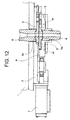
- Examples of structures of the slide valve device include a toggle mechanism in which a surface pressure is manually applied and released. Further, as another example, there may be given a slide valve device having a two-layer structure (Japanese Patent Application No. 2004-327405 ), which is manufactured by the applicants of the present invention as illustrated in FIG. 12 . That is, a fixed plate 3 is incorporated in a base frame 2 fixed to a bottom portion of a molten metal vessel 1, and a slide plate 5 and a shooting nozzle 6 are supported in a slide case 4 positioned below the fixed plate 3.
- Japanese Patent Application No. 2004-327405 Japanese Patent Application No. 2004-327405
- a nozzle hole 3a of the fixed plate 3 and a nozzle hole 5a of the slide plate 5 are caused to match or mismatch with each other.
- control is performed for an outflow of a molten metal which flows downward from the molten metal vessel 1 through an insertion nozzle 8.
- the slide case 4 is biased upward by using springs 12 through a pressing means in which rollers (movable bodies) 14 sliding on a support surface 13 are used, and the slide plate 5 is brought into contact with the fixed plate 3 with a predetermined pressing force.
- the slide case 4 having the rollers 14 is openable and closable through an intermediation of an axial support portion 15, and hence replacement of a fireproof material may be performed.
- Patent Document 1 The pressing means in the slide valve device having a similar basic structure as described in the above structure is disclosed in Patent Document 1, for example. Further, in the sliding nozzle device provided with a surface pressure application/release mechanism disclosed in Patent Document 2 (not shown), application and release of the surface pressure to the elastic means may be achieved through a movement of the pressing member, and the application and release of the surface pressure and the opening/closing operation of the flow path may be achieved by means of independent driving mechanism.
- the conventional slide valve devices are structured as described above, and hence the following problems are present. That is, in a first conventional structure in which the toggle mechanism described above is used, the surface pressure is manually applied and released. Therefore, the operation is highly heavy physical work to be conducted under high temperature. Further, in a second conventional structure disclosed in the specification of Japanese Patent Application No. 2004-327405 described above, the surface pressure may easily be applied and released by means of a cylinder drive. However, owing to a two-layer structure, it is structurally impossible to apply three-layer structure thereto. In addition, surplus sliding strokes are required for releasing the surface pressure, and hence the lengths of the device main body and the cylinder are increased. As a result, the device main body and the cylinder are increased in size.
- a third conventional structure disclosed in Patent Document 1 described above is difficult to be applied to the three-layer structure.
- a shape thereof becomes larger and the structure thereof becomes complicate.
- a fourth conventional structure disclosed in Patent Document 2 described above the structure thereof is extremely complicated because the pressing members are necessary to turn, and the toggle arms, etc. are required.
- a slide valve device for automatic surface pressure application according to the present invention includes:
- the slide valve device for automatic surface pressure application is structured as follows, and hence the following effects can be obtained. That is, in the three-layer structure constituted by the fixed plate, the slide plate, and the seal plate, only the slide plate is slid so as to perform control and an ON/OFF operation of the flow of hot water, and the seal case and the slide case are coupled with each other by means of the coupling means so as to be slid.
- the surface pressure is applied and released by means of the movable bodies such as rollers sliding on the support surface, whereby the configuration can be downsized and simplified. Further, owing to the above-mentioned effect, the heavy physical work conducted under high temperature is eliminated, whereby operability can be significantly increased.
- FIG. 1 illustrates a state of a use position (fully closed position) of a slide valve device 20.
- a bottom lower surface 1a of a molten metal vessel 1 is provided with a fixed plate 3 having a nozzle hole 3a communicating with an insertion nozzle 8 through an intermediation of a base frame 2.
- a slide case 4 having a slide plate 5 provided with a nozzle hole 5a is connected through an intermediation of a guide piece 4b to a hydraulic or electrical actuator 7. With the activation of the actuator 7, only the slide case 4 can be independently slid in a horizontal direction in the drawing.
- the slide case 4 can be bent downward in the drawing owing to an axial support portion 4a provided on a side of the guide piece 4b.
- a seal case 21 having a seal plate 21a below the slide case 4 is similarly openable and closable through an intermediation of an axial support portion 15 while applying the structure illustrated in the conventional structure of FIG. 9 . Therefore, the slide case 4 can be bent after the seal case 21 is released.
- the guide piece 4b and the seal case 21 are formed to be integrally slidable by means of a coupling means 23 such as a connecting pin inserted into a coupling hole 22. In the coupled state, the slide case 4 and the seal case 21 can be slid by means of the actuator 7.
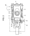
- FIG. 2 is a plan view of FIG. 1 .
- the seal case 21 is provided with a stopper 24 pivotable only by 90 degrees from a horizontal direction to a vertical direction and vice versa.
- a plate-like heat insulating cover 25 is provided pivotably toward the base frame 2 through an intermediation of an axial support portion 27 as illustrated in FIG. 4 .
- the stopper 24 is used for limiting the sliding range of the seal case 21 which comes into contact with protrusions or the like (not shown) during sliding.
- the heat insulating cover 25 is allowed to assume a closing state when the stopper 24 is situated at a horizontal position (solid line), and is not allowed to assume the closing state when situated at a vertical position (dotted line).
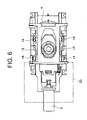
- FIG. 3 is a sectional view taken in the arrow A direction of FIG. 1 .
- a spring holder 30 is operably held to the base frame 2 through an intermediation of springs 12.
- the movable body 14 provided on each side of the seal case 21 is held in slidable contact with the support surface 13 formed on the bottom surface of the spring holder 30. Accordingly, when the movable body 14 moves on the support surface 13 owing to sliding of the seal case 21, the spring holder 30 vertically moves, whereby the surface pressure can be applied and released.
- the movable body 14 is detached from the support surface 13 when the seal case 21 and the slide case 4 are slid together in the state of being coupled with each other by means of the coupling means 23. As a result, the surface pressure can be released as described above.
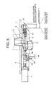
- the slide case 4 is situated at the fully closed position (K1 of FIGS. 1 and 5 ), and the stopper 24 is raised after opening of the heat insulating cover 25.
- the connecting pin 23 is inserted into a hole (not shown) provided to the guide piece 4b of the slide case 4 from a side of the seal case 21. In this manner, the seal case 21 and the slide case 4 are integrally coupled with each other.
- the seal case 21 and the slide case 4 are pivoted through the intermediation of the axial support portion 15 so as to be released, whereby it is possible to perform replacement and the like of the fireproof materials of the portions of the slide case 4 and the seal case 21. Further, after completion of the replacement of the fireproof materials, maintenance, and the like of the portions, the surface pressure is applied by means of procedure opposite to the above-mentioned procedure. In this manner, a maintenance operation is finished, and the slide valve device 20 can be reused for molding.
- an attachment/detachment position D of the coupling means 23 for coupling the slide case 4 and the seal case 21 is set to be the fully opened position K2 or the fully closed position K1 of a use stroke ST1 upon which only the slide case 4 is caused to be slid for performing an OPENING/CLOSING (ON/OFF) operation of the nozzle.
- the use stroke ST1 covers a range wider than that of a surface pressure release stroke ST2 which is performed through sliding of the slide case 4 together with the above-mentioned seal case 21 and with which the surface pressure is applied and released.
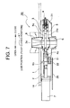
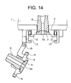
- FIGS. 7 to 11 illustrate other modes of the present invention.
- the same parts as those in FIGS. 1 to 6 are denoted by the same reference symbols, and only the parts different therefrom are described. That is, while the connecting pin 23 and the stopper 24 serving as coupling means are separated from each other in the modes of FIGS. 1 to 6 , the connecting pin 23 and the stopper 24 are integrated with each other so as to form a coupling stopper 31 of integrated type in the modes of FIGS. 7 to 11 .
- the stopper 24 is rotatably supported with respect to the connecting pin 23 in a bendable manner. Therefore, the coupling stopper 31 obtains the same coupling operation as that of the connecting pin 23 by being inserted into the coupling hole 22, and obtains the same stopper operation as that of the stopper 24 by bending the stopper 24.
Landscapes
- Engineering & Computer Science (AREA)
- Mechanical Engineering (AREA)
- Casting Support Devices, Ladles, And Melt Control Thereby (AREA)
Applications Claiming Priority (2)
| Application Number | Priority Date | Filing Date | Title |
|---|---|---|---|
| JP2006158356A JP4757714B2 (ja) | 2006-06-07 | 2006-06-07 | 自動面圧負荷スライドバルブ装置 |
| PCT/JP2007/061272 WO2007142178A1 (fr) | 2006-06-07 | 2007-06-04 | Dispositif tiroir pour application d'une pression superficielle automatique |
Publications (3)
| Publication Number | Publication Date |
|---|---|
| EP2039445A1 true EP2039445A1 (fr) | 2009-03-25 |
| EP2039445A4 EP2039445A4 (fr) | 2013-03-27 |
| EP2039445B1 EP2039445B1 (fr) | 2014-06-25 |
Family
ID=38801429
Family Applications (1)
| Application Number | Title | Priority Date | Filing Date |
|---|---|---|---|
| EP07744654.0A Ceased EP2039445B1 (fr) | 2006-06-07 | 2007-06-04 | Dispositif tiroir pour application d'une pression superficielle automatique |
Country Status (4)
| Country | Link |
|---|---|
| US (1) | US8002155B2 (fr) |
| EP (1) | EP2039445B1 (fr) |
| JP (1) | JP4757714B2 (fr) |
| WO (1) | WO2007142178A1 (fr) |
Cited By (2)
| Publication number | Priority date | Publication date | Assignee | Title |
|---|---|---|---|---|
| EP2463045A4 (fr) * | 2009-12-25 | 2017-01-18 | Shinagawa Refractories Co., Ltd | Appareil à soupape à tiroir pour l'application automatique de pression de surface et procédé d'application de pression de surface correspondant |
| EP4088837A1 (fr) * | 2021-05-14 | 2022-11-16 | Refractory Intellectual Property GmbH & Co. KG | Procédé, en particulier de mise en état d'une fermeture coulissante sur un cuve contenant du métal fondu, ainsi que fermeture coulissante |
Families Citing this family (8)
| Publication number | Priority date | Publication date | Assignee | Title |
|---|---|---|---|---|
| HUE028952T2 (en) * | 2008-04-17 | 2017-01-30 | Stopinc Ag | Locking plate and gate valve on the melting hole of a metal melt tank |
| PL2268433T3 (pl) * | 2008-04-17 | 2014-03-31 | Stopinc Ag | Zamknięcie suwakowe do zbiornika zawierającego płynny metal |
| JP5283772B1 (ja) | 2012-06-28 | 2013-09-04 | 品川リフラクトリーズ株式会社 | 自動面圧負荷スライドバルブ装置 |
| JP6363921B2 (ja) * | 2014-09-25 | 2018-07-25 | 黒崎播磨株式会社 | スライディングノズル装置におけるスライド金枠の開閉構造 |
| JP6423691B2 (ja) * | 2014-11-18 | 2018-11-14 | 黒崎播磨株式会社 | スライディングノズル装置のスライド金枠と駆動装置との連結切り替え構造 |
| KR101675669B1 (ko) * | 2015-03-26 | 2016-11-11 | 현대제철 주식회사 | 턴디시 장치 |
| KR101917299B1 (ko) * | 2016-11-22 | 2018-11-12 | 주식회사 대주기공 | 슬라이드 게이트의 면압풀림 방지장치 |
| PL3930941T3 (pl) * | 2019-02-28 | 2024-02-26 | Vesuvius Group, S.A. | Zawór zasuwowy zawierający wózek |
Citations (1)
| Publication number | Priority date | Publication date | Assignee | Title |
|---|---|---|---|---|
| AU2005303181A1 (en) * | 2004-11-11 | 2006-05-18 | Shinagawa Refractories Co., Ltd. | Slide valve device in casting facility |
Family Cites Families (6)
| Publication number | Priority date | Publication date | Assignee | Title |
|---|---|---|---|---|
| CH673097A5 (en) | 1986-08-20 | 1990-02-15 | Stopinc Ag | Metallurgical vessel sliding closure |
| JPH06155007A (ja) * | 1992-11-16 | 1994-06-03 | Shinagawa Refract Co Ltd | カートリッジ式スライドバルブのカートリッジ固定装置 |
| JP2831890B2 (ja) | 1993-02-05 | 1998-12-02 | 黒崎窯業株式会社 | 面圧負荷及び解除機構を備えたスライディングノズル装置 |
| JPH0780611A (ja) * | 1993-09-10 | 1995-03-28 | Kurosaki Refract Co Ltd | 溶鋼鋳造における初期開孔方法 |
| JP4155093B2 (ja) | 2003-03-04 | 2008-09-24 | 株式会社島津製作所 | イオン源およびイオンビーム装置 |
| JP4344217B2 (ja) * | 2003-10-30 | 2009-10-14 | 品川白煉瓦株式会社 | スライドバルブの面圧負荷装置 |
-
2006
- 2006-06-07 JP JP2006158356A patent/JP4757714B2/ja active Active
-
2007
- 2007-06-04 US US12/227,941 patent/US8002155B2/en not_active Expired - Fee Related
- 2007-06-04 EP EP07744654.0A patent/EP2039445B1/fr not_active Ceased
- 2007-06-04 WO PCT/JP2007/061272 patent/WO2007142178A1/fr active Application Filing
Patent Citations (1)
| Publication number | Priority date | Publication date | Assignee | Title |
|---|---|---|---|---|
| AU2005303181A1 (en) * | 2004-11-11 | 2006-05-18 | Shinagawa Refractories Co., Ltd. | Slide valve device in casting facility |
Non-Patent Citations (1)
| Title |
|---|
| See also references of WO2007142178A1 * |
Cited By (3)
| Publication number | Priority date | Publication date | Assignee | Title |
|---|---|---|---|---|
| EP2463045A4 (fr) * | 2009-12-25 | 2017-01-18 | Shinagawa Refractories Co., Ltd | Appareil à soupape à tiroir pour l'application automatique de pression de surface et procédé d'application de pression de surface correspondant |
| EP4088837A1 (fr) * | 2021-05-14 | 2022-11-16 | Refractory Intellectual Property GmbH & Co. KG | Procédé, en particulier de mise en état d'une fermeture coulissante sur un cuve contenant du métal fondu, ainsi que fermeture coulissante |
| WO2022238564A1 (fr) * | 2021-05-14 | 2022-11-17 | Refractory Intellectual Property Gmbh & Co. Kg | Procédé de maintenance d'un élément de fermeture coulissant sur un récipient contenant un métal fondu et élément de fermeture coulissant |
Also Published As
| Publication number | Publication date |
|---|---|
| EP2039445A4 (fr) | 2013-03-27 |
| WO2007142178A1 (fr) | 2007-12-13 |
| EP2039445B1 (fr) | 2014-06-25 |
| US8002155B2 (en) | 2011-08-23 |
| JP4757714B2 (ja) | 2011-08-24 |
| US20090184139A1 (en) | 2009-07-23 |
| JP2007326120A (ja) | 2007-12-20 |
Similar Documents
| Publication | Publication Date | Title |
|---|---|---|
| EP2039445B1 (fr) | Dispositif tiroir pour application d'une pression superficielle automatique | |
| EP2829354B1 (fr) | Dispositif de mandrin | |
| EP2463045B1 (fr) | Appareil à soupape à tiroir pour l'application automatique de pression de surface et procédé d'application de pression de surface correspondant | |
| WO2005046953A3 (fr) | Ensemble obturateur | |
| AU2013282509B2 (en) | Slide valve device for automatic surface pressure application | |
| US20080272157A1 (en) | Sliding Nozzle Device and Pouring Device | |
| JP6467511B2 (ja) | スライド金枠の位置決め機構 | |
| WO2019008929A1 (fr) | Dispositif de porte coulissante | |
| US9707770B2 (en) | Fluid ejection device | |
| WO2016080378A1 (fr) | Structure de commutation de connexion destinée à commuter la connexion entre un dispositif d'entraînement et un cadre de métal coulissant de dispositif de buse coulissante | |
| JP3614817B2 (ja) | スライドバルブの面圧負荷装置 | |
| JP2017221960A (ja) | スライディングゲート | |
| US7258256B2 (en) | Surface pressure load device of slide valve | |
| CN213419944U (zh) | 用于控制液态金属流出冶金容器的滑动闸阀及其系统 | |
| US11766717B2 (en) | Sliding gate device | |
| KR101917299B1 (ko) | 슬라이드 게이트의 면압풀림 방지장치 | |
| JP2016159345A (ja) | 浸漬ノズル脱着機構及びその脱着方法並びにそれを有するスライドバルブ装置 | |
| CN211807614U (zh) | 一种脱模装置 | |
| WO2023145463A1 (fr) | Appareil à busette coulissante | |
| JPS6254143A (ja) | 開口部密閉装置 | |
| JP2016068090A (ja) | 鋳造金型装置 |
Legal Events
| Date | Code | Title | Description |
|---|---|---|---|
| PUAI | Public reference made under article 153(3) epc to a published international application that has entered the european phase |
Free format text: ORIGINAL CODE: 0009012 |
|
| 17P | Request for examination filed |
Effective date: 20081219 |
|
| AK | Designated contracting states |
Kind code of ref document: A1 Designated state(s): AT BE BG CH CY CZ DE DK EE ES FI FR GB GR HU IE IS IT LI LT LU LV MC MT NL PL PT RO SE SI SK TR |
|
| AX | Request for extension of the european patent |
Extension state: AL BA HR MK RS |
|
| RBV | Designated contracting states (corrected) |
Designated state(s): CZ DE GB |
|
| DAX | Request for extension of the european patent (deleted) | ||
| REG | Reference to a national code |
Ref country code: DE Ref legal event code: R079 Ref document number: 602007037334 Country of ref document: DE Free format text: PREVIOUS MAIN CLASS: B22D0011100000 Ipc: B22D0041400000 |
|
| A4 | Supplementary search report drawn up and despatched |
Effective date: 20130221 |
|
| RIC1 | Information provided on ipc code assigned before grant |
Ipc: B22D 41/40 20060101AFI20130215BHEP |
|
| GRAP | Despatch of communication of intention to grant a patent |
Free format text: ORIGINAL CODE: EPIDOSNIGR1 |
|
| INTG | Intention to grant announced |
Effective date: 20140210 |
|
| GRAS | Grant fee paid |
Free format text: ORIGINAL CODE: EPIDOSNIGR3 |
|
| GRAA | (expected) grant |
Free format text: ORIGINAL CODE: 0009210 |
|
| AK | Designated contracting states |
Kind code of ref document: B1 Designated state(s): CZ DE GB |
|
| REG | Reference to a national code |
Ref country code: GB Ref legal event code: FG4D |
|
| REG | Reference to a national code |
Ref country code: DE Ref legal event code: R096 Ref document number: 602007037334 Country of ref document: DE Effective date: 20140814 |
|
| REG | Reference to a national code |
Ref country code: DE Ref legal event code: R097 Ref document number: 602007037334 Country of ref document: DE |
|
| PLBE | No opposition filed within time limit |
Free format text: ORIGINAL CODE: 0009261 |
|
| STAA | Information on the status of an ep patent application or granted ep patent |
Free format text: STATUS: NO OPPOSITION FILED WITHIN TIME LIMIT |
|
| 26N | No opposition filed |
Effective date: 20150326 |
|
| REG | Reference to a national code |
Ref country code: DE Ref legal event code: R097 Ref document number: 602007037334 Country of ref document: DE Effective date: 20150326 |
|
| PGFP | Annual fee paid to national office [announced via postgrant information from national office to epo] |
Ref country code: DE Payment date: 20210511 Year of fee payment: 15 Ref country code: CZ Payment date: 20210518 Year of fee payment: 15 |
|
| PGFP | Annual fee paid to national office [announced via postgrant information from national office to epo] |
Ref country code: GB Payment date: 20210512 Year of fee payment: 15 |
|
| REG | Reference to a national code |
Ref country code: DE Ref legal event code: R119 Ref document number: 602007037334 Country of ref document: DE |
|
| PG25 | Lapsed in a contracting state [announced via postgrant information from national office to epo] |
Ref country code: CZ Free format text: LAPSE BECAUSE OF NON-PAYMENT OF DUE FEES Effective date: 20220604 |
|
| GBPC | Gb: european patent ceased through non-payment of renewal fee |
Effective date: 20220604 |
|
| PG25 | Lapsed in a contracting state [announced via postgrant information from national office to epo] |
Ref country code: GB Free format text: LAPSE BECAUSE OF NON-PAYMENT OF DUE FEES Effective date: 20220604 Ref country code: DE Free format text: LAPSE BECAUSE OF NON-PAYMENT OF DUE FEES Effective date: 20230103 |