EP2038191B1 - Pack for cigarettes - Google Patents
Pack for cigarettes Download PDFInfo
- Publication number
- EP2038191B1 EP2038191B1 EP07726177A EP07726177A EP2038191B1 EP 2038191 B1 EP2038191 B1 EP 2038191B1 EP 07726177 A EP07726177 A EP 07726177A EP 07726177 A EP07726177 A EP 07726177A EP 2038191 B1 EP2038191 B1 EP 2038191B1
- Authority
- EP
- European Patent Office
- Prior art keywords
- pack
- front wall
- region
- wall
- collar
- Prior art date
- Legal status (The legal status is an assumption and is not a legal conclusion. Google has not performed a legal analysis and makes no representation as to the accuracy of the status listed.)
- Expired - Fee Related
Links
Images


Classifications
-
- B—PERFORMING OPERATIONS; TRANSPORTING
- B65—CONVEYING; PACKING; STORING; HANDLING THIN OR FILAMENTARY MATERIAL
- B65D—CONTAINERS FOR STORAGE OR TRANSPORT OF ARTICLES OR MATERIALS, e.g. BAGS, BARRELS, BOTTLES, BOXES, CANS, CARTONS, CRATES, DRUMS, JARS, TANKS, HOPPERS, FORWARDING CONTAINERS; ACCESSORIES, CLOSURES, OR FITTINGS THEREFOR; PACKAGING ELEMENTS; PACKAGES
- B65D5/00—Rigid or semi-rigid containers of polygonal cross-section, e.g. boxes, cartons or trays, formed by folding or erecting one or more blanks made of paper
- B65D5/42—Details of containers or of foldable or erectable container blanks
- B65D5/44—Integral, inserted or attached portions forming internal or external fittings
- B65D5/52—External stands or display elements for contents
- B65D5/5213—Internal elements supporting the contents and movable for displaying them, e.g. movable bottoms or trays
-
- B—PERFORMING OPERATIONS; TRANSPORTING
- B65—CONVEYING; PACKING; STORING; HANDLING THIN OR FILAMENTARY MATERIAL
- B65D—CONTAINERS FOR STORAGE OR TRANSPORT OF ARTICLES OR MATERIALS, e.g. BAGS, BARRELS, BOTTLES, BOXES, CANS, CARTONS, CRATES, DRUMS, JARS, TANKS, HOPPERS, FORWARDING CONTAINERS; ACCESSORIES, CLOSURES, OR FITTINGS THEREFOR; PACKAGING ELEMENTS; PACKAGES
- B65D5/00—Rigid or semi-rigid containers of polygonal cross-section, e.g. boxes, cartons or trays, formed by folding or erecting one or more blanks made of paper
- B65D5/42—Details of containers or of foldable or erectable container blanks
- B65D5/72—Contents-dispensing means
- B65D5/721—Contents-dispensing means consisting of mobile elements forming part of the containers or attached to the containers
-
- B—PERFORMING OPERATIONS; TRANSPORTING
- B65—CONVEYING; PACKING; STORING; HANDLING THIN OR FILAMENTARY MATERIAL
- B65D—CONTAINERS FOR STORAGE OR TRANSPORT OF ARTICLES OR MATERIALS, e.g. BAGS, BARRELS, BOTTLES, BOXES, CANS, CARTONS, CRATES, DRUMS, JARS, TANKS, HOPPERS, FORWARDING CONTAINERS; ACCESSORIES, CLOSURES, OR FITTINGS THEREFOR; PACKAGING ELEMENTS; PACKAGES
- B65D85/00—Containers, packaging elements or packages, specially adapted for particular articles or materials
- B65D85/07—Containers, packaging elements or packages, specially adapted for particular articles or materials for compressible or flexible articles
- B65D85/08—Containers, packaging elements or packages, specially adapted for particular articles or materials for compressible or flexible articles rod-shaped or tubular
- B65D85/10—Containers, packaging elements or packages, specially adapted for particular articles or materials for compressible or flexible articles rod-shaped or tubular for cigarettes
- B65D85/1009—Containers, packaging elements or packages, specially adapted for particular articles or materials for compressible or flexible articles rod-shaped or tubular for cigarettes provided with proffering means
-
- B—PERFORMING OPERATIONS; TRANSPORTING
- B65—CONVEYING; PACKING; STORING; HANDLING THIN OR FILAMENTARY MATERIAL
- B65D—CONTAINERS FOR STORAGE OR TRANSPORT OF ARTICLES OR MATERIALS, e.g. BAGS, BARRELS, BOTTLES, BOXES, CANS, CARTONS, CRATES, DRUMS, JARS, TANKS, HOPPERS, FORWARDING CONTAINERS; ACCESSORIES, CLOSURES, OR FITTINGS THEREFOR; PACKAGING ELEMENTS; PACKAGES
- B65D85/00—Containers, packaging elements or packages, specially adapted for particular articles or materials
- B65D85/07—Containers, packaging elements or packages, specially adapted for particular articles or materials for compressible or flexible articles
- B65D85/08—Containers, packaging elements or packages, specially adapted for particular articles or materials for compressible or flexible articles rod-shaped or tubular
- B65D85/10—Containers, packaging elements or packages, specially adapted for particular articles or materials for compressible or flexible articles rod-shaped or tubular for cigarettes
- B65D85/1036—Containers formed by erecting a rigid or semi-rigid blank
Definitions
- the invention relates to a pack of two packing parts, namely an outer pack with at least one front wall, namely outer front wall and an inner part with at least one front wall, which is connected by means of a mounted on the front wall connecting strap or joint flap with the outer front wall inside wherein parts of the outer package, namely subpackets, are pivotable about a bottom hinge relative to each other in an open and a closed position.
- a cigarette pack with two pivotally connected part packs is known by WO 2006/061563 ,
- the two sub-packages are pivotally connected to each other in the area of a common bottom wall.
- the two part packs are arranged in a spread position.
- the part packs together form an outer pack.
- This is connected in the region of an outer front wall with an inner part of the pack, namely with a modified collar.
- This has the connecting or joint flap, which is formed as part or as an extension of a collar front wall at the bottom of the collar. In order to bring the joint flap in the operative position, it requires a folding over of the extension against the collar front wall.
- a in this position of the joint flap upwardly directed edge strip is connected to the inside of the outer pack by gluing.
- the object underlying the invention is therefore to make the blanks for the outer packing and / or for the inner part machine-friendly.
- the package according to the invention is characterized in that the hinge or connecting strap formed as part of the (inner) front wall of the inner pack or the inner part by an approximately U-shaped punching and a free, a top or end wall the pack facing end-side portion is attached to the outside on the inside of the outer front wall, in particular by gluing.
- the procedure according to the invention is that the inner packing or a separate inner part is manufactured in a first working step and attached to the contents of the package - cigarette block - or folded around it.
- the formed inner unit is wrapped by a blank of the outer package.
- the packaging steps expediently proceed in successive or adjacent folding turrets of essentially conventional design.
- the connecting means namely glue, is mounted on the outside of the joint flap, so that when folding the blank for the outer pack it is connected without additional work step with the joint flap.
- a further feature according to the invention consists in that the inner packing surrounds the contents of the package at least in the region of a front side, in the region of a rear side and in the region of the bottom, and preferably also has side walls of overlapping inside side tabs.
- the inner pack is formed approximately cup-shaped, wherein the inner front wall acts in the upper region as (conventional) collar of a pack of the type folding box.
- the inner package and the outer package are connected to one another in the area of rear walls, that is to say the inner rear wall and the outer rear wall, in particular by bonding in an upper, frontal region and at the bottom in a bottom region.
- a rear edge facing the transverse edge of the outer bottom wall forms the line joint for pivoting the part packs of the outer pack.
- an inner part - instead of an inner packing - designed in the manner of a collar and provided with preferably two adjacent joint or joint plates. Between these, a web is formed centrally to stabilize the front wall of the inner part or of the collar.
- the cuboidal packs shown as exemplary embodiments serve to receive cigarettes 10 as package contents.
- the cigarettes are 10 as Cigarette group 11 and surrounded by an inner blank 12 of paper, tin or the like to form a cigarette block thirteenth
- the pack for receiving the cigarette block 13 consists of at least two packing parts, namely an inner part and an outer part.
- the latter is formed as the package contents largely surrounding outer package 14.
- the inner part is formed as an inner pack 15 which is partially or completely surrounded by the outer pack 14.
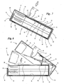
- Fig. 1 shows an expanded blank for the outer pack 14 with longitudinally successive areas for an outer front wall 16, a subsequent outer bottom wall 17 and an outer rear wall 18.
- an inner tab 19 is attached and
- outer side tabs 22, 23, which together in the closed position of the pack an outer side wall 21 of the outside -Packung 14 form on opposite narrow sides.
- the mutually associated outer side tabs 22, 23 are not connected to each other by gluing, but freely relative to each other movable.
- side corner tabs 24 are attached on the front wall 20 side corner tabs 24.
- Opposite end-corner flaps 25 are arranged in extension of the outer side tabs 23.
- bottom corner tabs 26 are mounted in extension of the outer bottom wall 17.
- the from the blank according to Fig. 1 formed outer pack 14 consists of two part packs 27, 28.
- the front part pack 27 consists essentially of the outer front wall 16, the (transversely folded) outer side flap 22, the transverse folded end wall 20 and the inside of the outside Side flaps 22 adjacent side corner flaps 24. These are connected to the outer side flaps 22 to form a box-shaped sub-package 27.
- the bottom corner tabs 26 are internally connected to the outer side tabs 22 and thus part of the front part of the package 27.
- the back part of package 28 consists of the outer rear wall 18, the folded outer side tabs 23, the transverse inner tabs 19 and End-corner tabs 25, the inside connected to the inner tab 19 by gluing are.
- the outer bottom wall 17 is connected via a joint, namely via a transversely directed bottom edge 29 with the partial pack 28.
- the two sub-packages 27, 28 are therefore pivotable about this bottom edge 29 to each other ( Fig. 8 ).
- This is according to the embodiment Fig. 1 to Fig. 10 formed as an inner package 15, for example, with a blank according to Fig. 2 , This is designed so that the package contents, ie the cigarette group 11 and the cigarette block 13, is largely enclosed by the inner packing 15, namely except for an upper, front and frontal area.
- the blank of the inner package 15 consists of an inner front wall 31, a longitudinally adjoining inner bottom wall 32 and a subsequent inner rear wall 33.
- Inner side walls 34 of the inner package 15 consist of laterally on the inner front wall 31 and inside Rear wall 33 attached folding flaps, namely inner side tabs 35 and inner side tabs 36. These cover each other to form the inner side walls 34 and are connected to each other.
- the side tabs 35 of the front wall 31 are outside.
- the inner pack 15 is formed due to the design of the blank as a cup pack (hard cup).
- the inner rear wall 33 extends (approximately) over the full height of the package or package contents.
- the inner front wall 31 is formed in dimensions and design, including the inner side flaps 35, as a conventional in packs of the type folding box collar. This includes a downwardly recessed, transversely directed collar edge 37.
- the inner side tabs 35 are provided with converging projections 38 which form the transition from the inner front wall 31 to the inner rear wall 33 in the region of the inner side walls 34.
- Corresponding to the limited by a curved edge projections 38 are opposite the inner side tabs 36 provided at the ends with recesses 62 corresponding to the projections 38 in shape and size.
- the contour of the collar edge 37 is formed corresponding to the opposite side of the inner rear wall 33, so that the blank for the inner pack 15 completely and without waste from a continuous web of material in the width of the blank according to Fig. 2 can be separated.
- the inner package 15 forms the (block-shaped) package contents for the outer package 14 with appropriate matching of the blanks according to Fig. 1 and Fig. 2 ,
- the inner package 15 is fully receptacle in the outer package 14.
- both packages 14, 15 are connected to each other, via glue joints 39 in the rear packing area, namely between outer rear wall 18 and inner rear wall 33.
- the glue joints 39 are mounted in an upper, frontal area on the one hand and in a lower, bottom-side area on the other hand.
- the opening position of the package, namely the spread of the partial packs 27, 28 is limited, by a retaining tab or joint flap 40 as a connecting member between the inner pack 15 and outer pack 14.
- the tab 40 is on the inner pack 15 in the area the inner front wall 31 attached or part thereof and with the outer front wall 16 connected inside.
- the hinge flap 40 extends over the full width of the front wall 31 due to a corresponding U-shaped punching with punching legs 41 in the region of a folding or packing edge formed between the inner side tabs 35 on the one hand and the inner front wall 31.
- the punching legs 41 extend approximately in a central region of the inner front wall 31 and terminate at a distance from the inner bottom wall 32.
- a transversely directed, arcuate transverse punching 42 extends at a significant distance from the frontal boundary of the inner front wall 31 and the collar edge 37 to form a transverse web 43rd
- the joint flap 40 is divided into two sections 46, 47 by two parallel hinge lines 44, 45.
- the outer end portion 47 is connected to the outer pack 14.
- the portion 47 is fully bonded by gluing to the inside of the outer front wall 16 ( Fig. 7, Fig. 8 ).
- the hinge flap 40 is lifted out of a starting position within the inner front wall 31, wherein the sections 46, 47 due to the hinge lines 44, 45 pivot against each other. In a middle position (dash-dotted in Fig.
- the outer package 14 is provided in the region of the outer front wall 16 with a preferably circular opening 48.
- an actuating force can be transmitted to the inner pack 15 by means of a finger ( Fig. 7, Fig. 8 ).
- the inner packing 15, namely its inner front wall 31 can have a printing or graphic design which is attached in the region of a circular contour of the transverse web 43 and is visible from the outside when the packing is closed.
- the preferably parallel lateral punching legs 41 extend beyond the transversely directed hinge line 44 (FIG. Fig. 3 ).
- the hinge line 44 is free and reliably effective in pivotal movements of the joint flap 40.
- the hinge lines 44, 45 may be defined by embossing and / or punching.
- the outer rear wall 18 has a flap 49 defined by perforation lines. This can extend in the predominant region of the outer rear wall 18, wherein an upright, linear joint 50 for the pivotable flap 49 preferably extends in the region of an upright packing edge on the package back side.
- the flap 49 cooperates with a graphic design 51 and / or informative printing on the inner rear wall 33 of the inner pack 15. When the flap 49 is opened, the design 51 becomes visible. When reclosing the flap 49, a tongue 52 can be inserted into a slot 53 of the inner rear wall 33.
- the embodiment according to Fig. 11 to Fig. 19 is in principle, namely in particular with regard to the arrangement and mode of action of joint plates 54, 55, in analog Way constructed as the embodiment described above.
- the outer pack 14 is taken over substantially unchanged, wherein the flap 49 is missing in the region of the outer rear wall 18.
- the blank corresponds to Fig. 1 the outer pack 14 of the embodiment according to Fig. 11 to Fig. 19 ,
- a special inner part 56 according to Fig. 11 provided which may be referred to as the collar of a folding box due to the design and function, namely collar front wall 57 and collar side flap 58 is made.
- the thus formed blank is placed on the front of the package contents, namely on the cigarette block 13 (FIG. Fig. 12 ), wherein the collar side tabs 58 abut against side surfaces of the cigarette block 13.
- the blank of the inner part 56 and the collar side tabs 58 extend to the bottom of the pack, are therefore based on the outer bottom wall 17 when the package is closed.
- the collar side tabs 58 are provided with corresponding edge-side support projections 59.
- each hinge flap 54, 55 is divided by hinge lines 44, 45 into sections 46, 47.
- the end-side portions 47 of both joint plates 54, 55 are (by gluing) connected to the inside of the outer front wall 16 ( Fig. 15, Fig. 16 ).
- the collar side flaps 58 are connected to the outer package 14, namely the back side subpackage 28, in the area of the outer side flaps 23 (by gluing).
- Opening and closing process take place in an analogous manner as in the previous embodiment.
- This also applies to the resilient action of the joint plates 54, 55 or the portion 46.
- the two joint plates 54, 55 are separated by a preferably central longitudinal ridge 61, which ensures the stability of the relatively small-area inner part 56, especially when opening and closing the package.
- Another special feature of this blank form, in particular according to Fig. 11 is that a transverse web 64 adjoining the hinge lines 44 is stabilized by the longitudinal web 61 despite a relatively small width. This makes it possible to produce the blank 56 with a relatively small dimension in the longitudinal direction, ie with a relatively narrow transverse web 64. The sufficient dimensional stability is ensured by the construction described.
- a first folding unit in particular folding turret
- the blank of the inner pack 15 is folded around the contents of the pack, that is to say the cigarette block 13, in a manner which is in principle conventional, so that the in Fig. 4 shown unit is created.
- a second folding unit in particular folding turret
- the outer package 14 is attached by folding the blank according to Fig. 1 around the inner pack 15 around.
- the hinge flap 40 or 54, 55, namely its portion 47, and / or the outer front wall 16 is provided with glue before the outer pack 14 is made.
- the outer front wall 16 comes into contact with the glue spots of the sections 47 (or vice versa), so that the connection between the hinge flap 40, 54, 55 and the outer pack 14 is made without special measures.
- the blanks of the packs or pack parts are expediently made of thin cardboard, as usual with folding boxes.
Description
Die Erfindung betrifft eine Packung aus zwei Packungsteilen, nämlich einer Außen-Packung mit mindestens einer Vorderwand, nämlich Außen-Vorderwand und einem Innenteil mit mindestens einer Vorderwand, die mittels einer an der Vorderwand angebrachten Verbindungslasche bzw. Gelenklasche mit der Außen-Vorderwand innenseitig verbunden ist, wobei Teile der Außen-Packung, nämlich Teilpackungen, um ein bodenseitiges Gelenk relativ zueinander schwenkbar sind in eine Öffnungs- und in eine Schließstellung.The invention relates to a pack of two packing parts, namely an outer pack with at least one front wall, namely outer front wall and an inner part with at least one front wall, which is connected by means of a mounted on the front wall connecting strap or joint flap with the outer front wall inside wherein parts of the outer package, namely subpackets, are pivotable about a bottom hinge relative to each other in an open and a closed position.
Eine Zigaretten-Packung mit zwei schwenkbar verbundenen Teilpackungen ist bekannt durch
Eine weitere Zigaretten-Packung mit zwei schwenkbar verbundenen Teilpackungen ist aus
Es ist Ziel der Erfindung, eine Packung der eingangs genannten Ausführung für insbesondere Zigaretten so weiterzuentwickeln, dass eine Fertigung auf weitgehend üblichen, leistungsfähigen Verpackungsmaschinen möglich ist. Die der Erfindung zugrunde liegende Aufgabe besteht demnach darin, die Zuschnitte für die Außen-Packung und/oder für das Innenteil maschinengerecht auszubilden.It is an object of the invention to further develop a package of the aforementioned embodiment for particular cigarettes so that a production on largely conventional, efficient packaging machines is possible. The object underlying the invention is therefore to make the blanks for the outer packing and / or for the inner part machine-friendly.
Zur Lösung dieser Aufgabe ist die erfindungsgemäße Packung dadurch gekennzeichnet, dass die Gelenk- bzw. Verbindungslasche als Teil der (Innen-)Vorderwand der Innen-Packung oder des Innenteils durch eine etwa U-förmige Stanzung gebildet und ein freier, einer Oberseite bzw. Stirnwand der Packung zugekehrter, endseitiger Abschnitt mit der Außenseite an der Innenseite der Außen-Vorderwand befestigt ist, insbesondere durch Klebung.To solve this problem, the package according to the invention is characterized in that the hinge or connecting strap formed as part of the (inner) front wall of the inner pack or the inner part by an approximately U-shaped punching and a free, a top or end wall the pack facing end-side portion is attached to the outside on the inside of the outer front wall, in particular by gluing.
Bei der Erfindung wird demnach aufgrund der Anordnung und Ausgestaltung der Verbindungs- bzw. Gelenklasche ein Umfalten der Lasche oder eines Teils als Zwischenschritt bei der Fertigung der Packung vermieden. Vielmehr wird erfindungsgemäß so vorgegangen, dass die Innen-Packung oder ein gesondertes Innenteil in einem ersten Arbeitsschritt gefertigt und am Packungsinhalt - Zigarettenblock - angebracht bzw. um diesen herumgefaltet wird. In einem zweiten Arbeitsschritt wird die gebildete Innen-Einheit von einem Zuschnitt der Außen-Packung umhüllt. Die Verpackungsschritte laufen zweckmäßigerweise in aufeinander folgenden bzw. aneinander anschließenden Faltrevolvern im Wesentlichen herkömmlicher Ausführung ab. Das Verbindungsmittel, nämlich Leim, ist auf der Außenseite der Gelenklasche angebracht, sodass beim Falten des Zuschnitts für die Außen-Packung diese ohne zusätzlichen Arbeitsschritt mit der Gelenklasche verbunden wird.In the invention, therefore, due to the arrangement and configuration of the joint or joint flap, a folding of the tab or a part as an intermediate step in the manufacture of the package is avoided. Rather, the procedure according to the invention is that the inner packing or a separate inner part is manufactured in a first working step and attached to the contents of the package - cigarette block - or folded around it. In a second step, the formed inner unit is wrapped by a blank of the outer package. The packaging steps expediently proceed in successive or adjacent folding turrets of essentially conventional design. The connecting means, namely glue, is mounted on the outside of the joint flap, so that when folding the blank for the outer pack it is connected without additional work step with the joint flap.
Eine weitere erfindungsgemäße Besonderheit besteht darin, dass die Innen-Packung den Packungsinhalt mindestens im Bereich einer Vorderseite, im Bereich einer Rückseite und im Bereich des Bodens umgibt, vorzugsweise darüber hinaus auch Seitenwände aus einander überdeckenden Innen-Seitenlappen aufweist. Vorzugsweise ist die Innen-Packung annähernd becherförmig ausgebildet, wobei die Innen-Vorderwand im oberen Bereich als (üblicher) Kragen einer Packung des Typs Klappschachtel wirkt. Innen-Packung und Außen-Packung sind im Bereich von Rückwänden, also Innen-Rückwand und Außen-Rückwand, miteinander verbunden, insbesondere durch Klebung in einem oberen, stirnseitigen Bereich und unten in einem bodenseitigen Bereich. Eine den Rückwänden zugekehrte Querkante der Außen-Bodenwand bildet das Liniengelenk zum Verschwenken der Teilpackungen der Außen-Packung.A further feature according to the invention consists in that the inner packing surrounds the contents of the package at least in the region of a front side, in the region of a rear side and in the region of the bottom, and preferably also has side walls of overlapping inside side tabs. Preferably, the inner pack is formed approximately cup-shaped, wherein the inner front wall acts in the upper region as (conventional) collar of a pack of the type folding box. The inner package and the outer package are connected to one another in the area of rear walls, that is to say the inner rear wall and the outer rear wall, in particular by bonding in an upper, frontal region and at the bottom in a bottom region. A rear edge facing the transverse edge of the outer bottom wall forms the line joint for pivoting the part packs of the outer pack.
Gemäß einer weiteren Besonderheit der Erfindung ist ein Innenteil - anstelle einer Innen-Packung - nach Art eines Kragens ausgebildet und mit vorzugsweise zwei nebeneinander liegenden Verbindungs- bzw. Gelenklaschen versehen. Zwischen diesen ist mittig ein Steg gebildet zur Stabilisierung der Vorderwand des Innenteils bzw. des Kragens.According to a further feature of the invention, an inner part - instead of an inner packing - designed in the manner of a collar and provided with preferably two adjacent joint or joint plates. Between these, a web is formed centrally to stabilize the front wall of the inner part or of the collar.
Weitere Merkmale und Besonderheiten der Erfindung werden nachfolgend anhand der Zeichnungen näher erläutert. Es zeigt:
- Fig. 1
- einen ausgebreiteten Zuschnitt für eine Außen-Packung,
- Fig. 2
- einen ausgebreiteten Zuschnitt für eine Innen-Packung,
- Fig. 3
- eine Einzelheit III des Zuschnitts gemäß
Fig. 2 in vergrößertem Maßstab, - Fig. 4
- eine mit Packungsinhalt versehene, fertige Innen-Packung in perspektivischer Darstellung,
- Fig. 5
- eine fertige (Gesamt-)Packung in perspektivischer Darstellung,
- Fig. 6
- die Packung gemäß
Fig. 5 mit Darstellung anderer Einzelheiten (Faltlappen), - Fig. 7
- einen Längsschnitt durch eine fertige, geschlossene Packung gemäß
Fig. 5 in der Schnittebene VII-VII derFig. 5 , in vergrößertem Maßstab, - Fig. 8
- die Packung in der Darstellung entsprechend
Fig. 7 in mehreren Öffnungs- bzw. Schließphasen, - Fig. 9
- die komplette Packung in Rückansicht, in perspektivischer Darstellung,
- Fig. 10
- die Packung gemäß
Fig. 9 mit einer geöffneten Rückklappe, - Fig. 11 1
- einen Zuschnitt für ein Innenteil eines anderen Ausführungsbeispiels einer Pa- ckung,
- Fig. 12
- einen Zigarettenblock mit Innenteil gemäß
Fig. 11 in perspektivischer Darstel- lung, - Fig. 13
- eine Packung in einer Darstellung analog
Fig. 5 mit einem Innenteil gemäßFig. 11 , - Fig. 14
- die Packung gemäß
Fig. 13 in einer Darstellung analogFig. 6 , - Fig. 15
- die Packung gemäß
Fig. 13 im Längsschnitt in der Schnittebene XV-XV derFig. 13 , bei vergrößertem Maßstab, - Fig. 16
- die Packung in einer Darstellung analog
Fig. 15 mit Öffnung- und Schließpha- sen, - Fig. 17
- die Packung in der Ausführung gemäß
Fig. 1 bis Fig. 10 in geöffneter Stellung bei perspektivischer Darstellung mit einer Schnittebene zu der Darstellung ent- sprechendFig. 8 , - Fig. 18
- eine Darstellung analog
Fig. 17 für das Ausführungsbeispiel gemäßFig. 11 bis Fig. 16 mit einer Schnittebene entsprechend Darstellung inFig. 16 , - Fig. 19
- eine perspektivische Darstellung der Packung mit Blick auf eine Außen-Vorder- wand in geöffneter Stellung.
- Fig. 1
- an unfolded blank for an outer pack,
- Fig. 2
- a spread blank for an inner pack,
- Fig. 3
- a detail III of the blank according to
Fig. 2 on an enlarged scale, - Fig. 4
- a packaged content, finished interior pack in perspective,
- Fig. 5
- a finished (total) pack in perspective,
- Fig. 6
- the pack according to
Fig. 5 with representation of other details (folding flaps), - Fig. 7
- a longitudinal section through a finished, closed package according to
Fig. 5 in the sectional plane VII-VII ofFig. 5 , on an enlarged scale, - Fig. 8
- the pack in the illustration accordingly
Fig. 7 in several opening or closing phases, - Fig. 9
- the complete pack in rear view, in perspective,
- Fig. 10
- the pack according to
Fig. 9 with an open flap, - Fig. 11 1
- a blank for an inner part of another embodiment of a package,
- Fig. 12
- a cigarette block with inner part according to
Fig. 11 in a perspective view, - Fig. 13
- a pack in a representation analog
Fig. 5 with an inner part according toFig. 11 . - Fig. 14
- the pack according to
Fig. 13 in a representation analogFig. 6 . - Fig. 15
- the pack according to
Fig. 13 in longitudinal section in the sectional plane XV-XV ofFig. 13 on an enlarged scale, - Fig. 16
- the pack in a representation analog
Fig. 15 with opening and closing phases, - Fig. 17
- the package in the design according to
Fig. 1 to Fig. 10 in the open position in the perspective view with a sectional plane corresponding to the representationFig. 8 . - Fig. 18
- a representation analog
Fig. 17 for the embodiment according to11 to FIG. 16 with a sectional plane as shown inFig. 16 . - Fig. 19
- a perspective view of the pack overlooking an outer front wall in the open position.
Die als Ausführungsbeispiele dargestellten quaderförmigen Packungen dienen zur Aufnahme von Zigaretten 10 als Packungsinhalt. Üblicherweise sind die Zigaretten 10 als Zigaretten-Gruppe 11 formiert und von einem Innenzuschnitt 12 aus Papier, Stanniol oder dergleichen umgebene unter Bildung eines Zigarettenblocks 13.The cuboidal packs shown as exemplary embodiments serve to receive
Die Packung zur Aufnahme des Zigarettenblocks 13 besteht aus mindestens zwei Packungsteilen, nämlich einem Innenteil und einem Außenteil. Letzterer ist als den Packungsinhalt weitgehend umgebende Außen-Packung 14 ausgebildet. Bei dem Ausführungsbeispiel gemäß
An der Stirnwand 20 sind Seiten-Ecklappen 24 angebracht. Gegenüberliegend sind Stirn-Ecklappen 25 in Verlängerung der Außen-Seitenlappen 23 angeordnet. Weiterhin sind Boden-Ecklappen 26 in Verlängerung der Außen-Bodenwand 17 angebracht.On the
Die aus dem Zuschnitt gemäß
Die Außen-Packung 14, insbesondere die frontseitige Teilpackung 27, wirkt zusammen mit einem Innenteil. Dieses ist bei dem Ausführungsbeispiel gemäß
Die Innen-Packung 15 ist aufgrund der Gestaltung des Zuschnitts als Becherpackung (Hartbecher) ausgebildet. Die Innen-Rückwand 33 erstreckt sich (annähernd) über die volle Höhe der Packung bzw. des Packungsinhalts. Die Innen-Vorderwand 31 ist hinsichtlich Abmessungen und Gestaltung, einschließlich der Innen-Seitenlappen 35, wie ein bei Packungen des Typs Klappschachtel üblicher Kragen ausgebildet. Hierzu gehört eine nach unten zurückgesetzte, quer gerichtete Kragenkante 37. Weiterhin sind die Innen-Seitenlappen 35 mit konvergierend ausgebildeten Vorsprüngen 38 versehen, die im Bereich der Innen-Seitenwände 34 den Übergang von der Innen-Vorderwand 31 zur Innen-Rückwand 33 bilden. Korrespondierend zu den durch eine geschwungene Kante begrenzten Vorsprüngen 38 sind gegenüberliegend die Innen-Seitenlappen 36 an den Enden mit Ausnehmungen 62 versehen, die in Form und Größe den Vorsprüngen 38 entsprechen. Auch die Kontur der Kragenkante 37 ist an der gegenüberliegenden Seite der Innen-Rückwand 33 korrespondierend ausgebildet, sodass der Zuschnitt für die Innen-Packung 15 komplett und ohne Abfall von einer fortlaufenden Materialbahn in der Breite des Zuschnitts gemäß
Die Innen-Packung 15 bildet für die Außen-Packung 14 den (blockförmigen) Packungsinhalt bei entsprechender Abstimmung der Zuschnitte gemäß
Die Öffnungsstellung der Packung, nämlich die Spreizstellung der Teilpackungen 27, 28 ist begrenzt, und zwar durch eine Haltelasche bzw. Gelenklasche 40 als Verbindungsorgan zwischen Innen-Packung 15 und Außen-Packung 14. Die Lasche 40 ist an der Innen-Packung 15 im Bereich der Innen-Vorderwand 31 angebracht bzw. Teil derselben und mit der Außen-Vorderwand 16 innenseitig verbunden.The opening position of the package, namely the spread of the
Bei dem Ausführungsbeispiel gemäß
Die Gelenklasche 40 ist durch zwei parallele Gelenklinien 44, 45 in zwei Abschnitte 46, 47 unterteilt. Der äußere, endseitige Abschnitt 47 ist mit der Außen-Packung 14 verbunden. Vorzugsweise ist der Abschnitt 47 vollflächig durch Klebung mit der Innenseite der Außen-Vorderwand 16 verbunden (
Um den Öffnungsvorgang zu erleichtern, ist die Außen-Packung 14 im Bereich der Außen-Vorderwand 16 mit einer vorzugsweise kreisförmigen Öffnung 48 versehen. Durch diese kann eine Betätigungskraft mittels Finger auf die Innen-Packung 15 übertragen werden (
Eine weitere Besonderheit ist ein Detail der Stanzung für die Gelenklasche 40. Die vorzugsweise parallelen seitlichen Stanzschenkel 41 erstrecken sich über die quer gerichtete Gelenklinie 44 hinweg (
Weiterhin ist eine Besonderheit im Bereich der Rückseite der Packung vorgesehen. Die Außen-Rückwand 18 weist eine durch Perforationslinien definierte Klappe 49 auf. Diese kann sich im überwiegenden Bereich der Außen-Rückwand 18 erstrecken, wobei ein aufrechtes, linienförmiges Gelenk 50 für die schwenkbare Klappe 49 vorzugsweise im Bereich einer aufrechten Packungskante an der Packungsrückseite verläuft. Die Klappe 49 wirkt zusammen mit einer grafischen Gestaltung 51 und/oder informativen Bedruckung an der Innen-Rückwand 33 der Innen-Packung 15. Beim Öffnen der Klappe 49 wird die Gestaltung 51 sichtbar. Bei Wiederverschließen der Klappe 49 kann eine Zunge 52 in einen Schlitz 53 der Innen-Rückwand 33 eingeführt werden.Furthermore, a special feature in the area of the back of the pack is provided. The outer
Das Ausführungsbeispiel gemäß
Anstelle einer weitgehend kompletten Innen-Packung ist bei diesem Ausführungsbeispiel ein besonderes Innenteil 56 gemäß
Im Bereich der Kragen-Vorderwand 57 ist das Verbindungsorgan mit Außen-Packung 14 angebracht. Es handelt sich um zwei nebeneinander liegende Gelenklaschen 54, 55, die ebenfalls durch U-förmige Stanzungen - wie bei der Gelenklasche 40 - gebildet sind, die - wie ebenfalls bei der Gelenklasche 40 - mit Restverbindungen 60 innerhalb der Kragen-Vorderwand 57 fixiert sind. Die Restverbindungen 60 werden beim erstmaligen Öffnen der Packung durchtrennt. Des Weiteren ist jede Gelenklasche 54, 55 durch Gelenklinien 44, 45 in Abschnitte 46, 47 unterteilt. Die endseitigen Abschnitte 47 beider Gelenklaschen 54, 55 sind (durch Klebung) mit der Innenseite der Außen-Vorderwand 16 verbunden (
Öffnungs- und Schließvorgang finden in analoger Weise statt wie beim vorangehenden Ausführungsbeispiel. Dies gilt auch für die federnde Wirkung der Gelenklaschen 54, 55 bzw. des Abschnitts 46. Die beiden Gelenklaschen 54, 55 sind durch einen vorzugsweise mittleren Längssteg 61 voneinander getrennt, der die Stabilität des verhältnismäßig kleinflächigen Innenteils 56 vor allem beim Öffnen und Schließen der Packung gewährleistet. Eine weitere Besonderheit dieser Zuschnittsform, insbesondere gemäß
Bei der Herstellung der beschriebenen Packungen wird zweckmäßigerweise so vorgegangen, dass in einem ersten Faltaggregat, insbesondere Faltrevolver, der Zuschnitt der Innen-Packung 15 in prinzipiell üblicher Weise um den Packungsinhalt, also den Zigarettenblock 13 herumgefaltet wird, sodass als Zwischenprodukt die in
- 1010
- ZigaretteCigarette
- 1111
- Zigaretten-GruppeCigarette group
- 1212
- Innenzuschnittinner blank
- 1313
- Zigarettenblockcigarette block
- 1414
- Außen-PackungOuter pack
- 1515
- Innen-PackungInside pack
- 1616
- Außen-VorderwandOutside front wall
- 1717
- Außen-BodenwandExterior floor wall
- 1818
- Außen-RückwandAn exterior rear wall
- 1919
- Innenlappeninner flap
- 2020
- Stirnwandbulkhead
- 2121
- Außen-SeitenwandExterior side wall
- 2222
- Außen-SeitenlappenOuter side tabs
- 2323
- Außen-SeitenlappenOuter side tabs
- 2424
- Seiten-EcklappenPages corner tabs
- 2525
- Stirn-EcklappenFront corner tabs
- 2626
- Boden-EcklappenBase corner tabs
- 2727
- Teilpackungpartial packing
- 2828
- Teilpackungpartial packing
- 2929
- Bodenkantebottom edge
- 3030
- 3131
- Innen-VorderwandInterior front wall
- 3232
- Innen-BodenwandInside bottom wall
- 3333
- Innen-RückwandInner rear wall
- 3434
- Innen-SeitenwandInterior sidewall
- 3535
- Innen-SeitenlappenInterior side tabs
- 3636
- Innen-SeitenlappenInterior side tabs
- 3737
- Kragenkantecollar edge
- 3838
- Vorsprunghead Start
- 3939
- Leimverbindungglue joint
- 4040
- Gelenklaschejoint plate
- 4141
- Stanzschenkelpunching leg
- 4242
- QuerstanzungCross punch
- 4343
- Querstegcrosspiece
- 4444
- Gelenkliniejoint line
- 4545
- Gelenkliniejoint line
- 4646
- Abschnittsection
- 4747
- Abschnittsection
- 4848
- Öffnungopening
- 4949
- Klappeflap
- 5050
- Gelenkjoint
- 5151
- Gestaltunglayout
- 5252
- Zungetongue
- 5353
- Schlitzslot
- 5454
- Gelenklaschejoint plate
- 5555
- Gelenklaschejoint plate
- 5656
- Innenteilinner part
- 5757
- Kragen-VorderwandCollar front wall
- 5858
- Kragen-SeitenlappenCollar side tabs
- 5959
- Stützvorsprungsupporting projection
- 6060
- Restverbindungresidual connection
- 6161
- Längssteglongitudinal web
- 6262
- Ausnehmungrecess
- 6363
- Kragenkantecollar edge
- 6464
- Querlappentransverse tabs
Claims (13)
- Pack made up of two pack parts, namely an outer pack (14) with at least one outer front wall (16) and an inner pack (15) or an inner part (56) with at least one front wall (31, 57), which is connected internally to the outer front wall (16) of the outer pack (14) by means of a connecting tab or articulation tab (40; 54, 55) fitted on the front wall (31, 57), wherein the outer pack (14) comprises two sub-packs (27, 28) which are connected to one another in a pivotable manner and of which the open position is limited by the articulation tab (40; 54, 55), characterized in that the connecting tab or articulation tab (40; 54, 55), as part of the inner front wall (31) or collar front wall (57), is formed by approximately U-shaped punch cuts (41, 42), and a peripheral portion (47) of the articulation tab, or a free peripheral piece of the same, which is directed towards a top side or end wall of the pack, is fastened internally, in particular by adhesive bonding, on the outer front wall (16).
- Pack according to Claim 1, characterized in that the articulation tab (40; 54, 55) is bounded by two lateral punched limbs (41) and a transverse punch cut (42), wherein the transverse punch cut (42) is directed towards an end side of the pack and/or a collar edge (37) of the inner pack (15) or of the inner part (56).
- Pack according to Claim 1 or 2, characterized in that the articulation tab (40; 54, 55) is subdivided, by two transversely directed, spaced-apart articulation lines (44, 45), into two portions (46, 47) which can be pivoted in relation to one another and of which the peripheral portion (47) is connected to the inside of the outer front wall (16).
- Pack according to Claim 1 or one of the further claims, characterized in that the articulation tab (40) extends over the entire width of the inner front wall (31) of the inner pack (15) and, in a region which is directed towards the collar edge (37), is bounded by a transverse crosspiece (43) connected to lateral folding lugs, namely inner side lugs (35).
- Pack according to Claim 1 or one of the further claims, characterized in that the inner pack (15) comprises a blank which more or less completely encloses pack contents, in particular a cigarette block (13), in particular in the manner of a carton pack, preferably with the formation of a free opening in the region of an end wall and of an adjacent region of the front wall and side walls.
- Pack according to Claim 1 or one of the further claims, characterized in that the outer pack (14) and inner pack (15) are connected to one another, in particular by adhesive bonding in the region of the outer rear wall (18) and inner rear wall (33), glue connections (39) being applied in a region adjacent to the end wall (20), on the one hand, and adjacent to the base wall (17), on the other hand.
- Pack according to Claim 1 or one of the further claims, characterized in that the outer pack (14), in the region of the outer rear wall (18), has a flap (49) defined by perforation lines, and the adjacent inner rear wall (33) of the inner pack (15) has printing at least in the region of the flap (49).
- Pack according to Claim 1 or one of the further claims, characterized in that the outer pack (14) or the blank thereof, in the region of an end wall (20), has side corner lugs (24) which adjoin this end wall laterally and are connected to adjacent outer side lugs (22), and in that outer side lugs (23), which adjoin the outer rear wall (18), have end corner lugs (25), which are connected to an inner lug (19) which extends in the region of an end surface of the pack or of the sub-pack (28).
- Pack according to Claim 1 or one of the further claims, characterized in that the inner pack (15) or the blank thereof, in the region of an inner front wall (31), has lateral inner side lugs (35) with a protrusion (38) bounded by oblique, curved edges, and in that inner side lugs (36), which are connected to the inner rear wall (33), have correspondingly shaped recesses (62) such that the blank for the inner pack (15) can be severed in a waste-free manner from a continuous web of the packaging material.
- Pack according to Claim 1 or one of the further claims, characterized in that the articulation tab (54, 55) is arranged in the region of a front wall (57) of a collar-like inner part (56), and the latter is connected to the outer front wall (16) via the articulation tab (54, 55).
- Pack according to Claim 1 or one of the further claims, characterized in that the inner front wall (31), in particular the collar front wall (57) of the inner part (56), has two adjacent, preferably corresponding articulation tabs (54, 55), which are both connected to the outer front wall (16) of the outer pack (14).
- Pack according to Claim 11 or one of the further claims, characterized in that a longitudinal crosspiece (61) is formed between the adjacent articulation tabs (54, 55).
- Pack according to Claim 10 or one of the further claims, characterized in that the collar-like inner part (56) extends, in the region of collar side lugs (58), as far as the base wall (17) of the outer pack (14), and is supported thereon in particular by peripheral supporting protrusions (59).
Priority Applications (1)
| Application Number | Priority Date | Filing Date | Title |
|---|---|---|---|
| PL07726177T PL2038191T3 (en) | 2006-07-12 | 2007-06-29 | Pack for cigarettes |
Applications Claiming Priority (2)
| Application Number | Priority Date | Filing Date | Title |
|---|---|---|---|
| DE102006032556A DE102006032556A1 (en) | 2006-07-12 | 2006-07-12 | Pack for cigarettes |
| PCT/EP2007/005755 WO2008006471A1 (en) | 2006-07-12 | 2007-06-29 | Pack for cigarettes |
Publications (2)
| Publication Number | Publication Date |
|---|---|
| EP2038191A1 EP2038191A1 (en) | 2009-03-25 |
| EP2038191B1 true EP2038191B1 (en) | 2010-08-25 |
Family
ID=38445260
Family Applications (1)
| Application Number | Title | Priority Date | Filing Date |
|---|---|---|---|
| EP07726177A Expired - Fee Related EP2038191B1 (en) | 2006-07-12 | 2007-06-29 | Pack for cigarettes |
Country Status (6)
| Country | Link |
|---|---|
| EP (1) | EP2038191B1 (en) |
| JP (1) | JP4834770B2 (en) |
| DE (2) | DE102006032556A1 (en) |
| PL (1) | PL2038191T3 (en) |
| RU (1) | RU2429173C2 (en) |
| WO (1) | WO2008006471A1 (en) |
Cited By (1)
| Publication number | Priority date | Publication date | Assignee | Title |
|---|---|---|---|---|
| US10926943B2 (en) | 2018-10-19 | 2021-02-23 | Altria Client Services Llc | Opening pack |
Families Citing this family (6)
| Publication number | Priority date | Publication date | Assignee | Title |
|---|---|---|---|---|
| CA2716350C (en) * | 2008-02-25 | 2013-08-06 | Japan Tobacco Inc. | Swing-open type package |
| DE102008035473A1 (en) * | 2008-07-30 | 2010-02-04 | Focke & Co.(Gmbh & Co. Kg) | Pack for cigarettes and method of making same |
| JP5855574B2 (en) | 2009-12-22 | 2016-02-09 | フィリップ・モーリス・プロダクツ・ソシエテ・アノニム | Packaging container with adhesive label |
| GB201001944D0 (en) * | 2010-02-05 | 2010-03-24 | Kind Consumer Ltd | A simulated smoking device |
| DE102010035939B4 (en) * | 2010-08-31 | 2014-11-13 | British American Tobacco (Germany) Gmbh | Pack for smoking articles with lid guided around two pivot axes |
| DE112015000413T5 (en) * | 2014-01-15 | 2016-10-13 | G.D Società per Azioni | Fixed open-pack for tobacco products |
Family Cites Families (6)
| Publication number | Priority date | Publication date | Assignee | Title |
|---|---|---|---|---|
| US5014906A (en) * | 1988-10-05 | 1991-05-14 | Gabriel Gero | Multiple purpose dispensing package and blank |
| NL1013920C1 (en) * | 1999-12-22 | 2001-06-25 | British American Tobacco Co | Cigarette packaging. |
| DE20107274U1 (en) * | 2000-05-15 | 2001-09-27 | British American Tobacco Co | Cigarette packet that can be opened with one hand |
| ITBO20000684A1 (en) * | 2000-11-23 | 2002-05-23 | Gd Spa | RIGID PACKAGE FOR CIGARETTES |
| ITBO20010749A1 (en) * | 2001-12-11 | 2003-06-11 | Gd Spa | RIGID ENCLOSURE FOR SMOKING ITEMS |
| GB0426825D0 (en) * | 2004-12-07 | 2005-01-12 | British American Tobacco Co | Package |
-
2006
- 2006-07-12 DE DE102006032556A patent/DE102006032556A1/en not_active Withdrawn
-
2007
- 2007-06-29 EP EP07726177A patent/EP2038191B1/en not_active Expired - Fee Related
- 2007-06-29 DE DE502007004868T patent/DE502007004868D1/en active Active
- 2007-06-29 PL PL07726177T patent/PL2038191T3/en unknown
- 2007-06-29 RU RU2009104339/12A patent/RU2429173C2/en not_active IP Right Cessation
- 2007-06-29 JP JP2009518745A patent/JP4834770B2/en not_active Expired - Fee Related
- 2007-06-29 WO PCT/EP2007/005755 patent/WO2008006471A1/en active Application Filing
Cited By (2)
| Publication number | Priority date | Publication date | Assignee | Title |
|---|---|---|---|---|
| US10926943B2 (en) | 2018-10-19 | 2021-02-23 | Altria Client Services Llc | Opening pack |
| US11511931B2 (en) | 2018-10-19 | 2022-11-29 | Altria Client Services Llc | Opening pack |
Also Published As
| Publication number | Publication date |
|---|---|
| EP2038191A1 (en) | 2009-03-25 |
| PL2038191T3 (en) | 2011-02-28 |
| RU2009104339A (en) | 2010-08-20 |
| RU2429173C2 (en) | 2011-09-20 |
| JP2009542541A (en) | 2009-12-03 |
| WO2008006471A1 (en) | 2008-01-17 |
| JP4834770B2 (en) | 2011-12-14 |
| DE502007004868D1 (en) | 2010-10-07 |
| DE102006032556A1 (en) | 2008-01-17 |
Similar Documents
| Publication | Publication Date | Title |
|---|---|---|
| EP2029446B1 (en) | Flip-top packet for cigarettes | |
| EP0625469B1 (en) | Package, especially hinge-lid-box | |
| EP1747153B1 (en) | Cigarette package | |
| EP1204571B1 (en) | Hinged-lid package for cigarettes | |
| EP0801010B2 (en) | Hinged-lid package, especially for cigarettes | |
| EP2038191B1 (en) | Pack for cigarettes | |
| EP1924505B1 (en) | Package foldable cutout | |
| EP0675056B1 (en) | Hinged-lid box for cigarettes or the like | |
| EP0778212B1 (en) | Hinged-lid box for cigarettes or the like | |
| WO2003091130A1 (en) | Cigarette pack comprising a slide and case | |
| EP0745541A1 (en) | Hinged-lid box for cigarettes | |
| EP3197787B1 (en) | Hinge-lid pack for cigarettes | |
| EP2841358B1 (en) | Cigarette package and method for production thereof | |
| DE4003104A1 (en) | Carton for packing chocolates - has tags projecting from side walls of body which engage slots in lid | |
| EP0547424B1 (en) | Package for paper handkerchiefs | |
| EP1542913A1 (en) | Folding packet | |
| EP0976660B1 (en) | Package for a group of articles and process for its manufacture | |
| EP0399250B1 (en) | Packaging web consisting of interconnected blank sheets | |
| EP0703160B1 (en) | Hinged-lid carton for cigarettes or the like | |
| WO2010097097A1 (en) | Folding box packaging, in particular for cigarettes or the like | |
| DE102005014864A1 (en) | cigarette pack | |
| EP2064134B1 (en) | Hinge-lid box for cigarettes and blank for hinge-lid boxes | |
| WO2005014435A1 (en) | Flip-top packet for cigarettes | |
| WO2002068293A1 (en) | Blank for a box with a hinged lid | |
| DE10243925A1 (en) | Folding packet for cigarettes comprises blank forming packet outer side flap and lid side flap, packet front wall and lid front wall, packet side wall and lid side wall, packet rear wall and lid rear wall, and edge connecting strip |
Legal Events
| Date | Code | Title | Description |
|---|---|---|---|
| PUAI | Public reference made under article 153(3) epc to a published international application that has entered the european phase |
Free format text: ORIGINAL CODE: 0009012 |
|
| 17P | Request for examination filed |
Effective date: 20090108 |
|
| AK | Designated contracting states |
Kind code of ref document: A1 Designated state(s): AT BE BG CH CY CZ DE DK EE ES FI FR GB GR HU IE IS IT LI LT LU LV MC MT NL PL PT RO SE SI SK TR |
|
| AX | Request for extension of the european patent |
Extension state: AL BA HR MK RS |
|
| RIN1 | Information on inventor provided before grant (corrected) |
Inventor name: HEIN, VIKTOR Inventor name: BUSE, HENRY |
|
| DAX | Request for extension of the european patent (deleted) | ||
| RBV | Designated contracting states (corrected) |
Designated state(s): DE GB IT PL RO TR |
|
| GRAP | Despatch of communication of intention to grant a patent |
Free format text: ORIGINAL CODE: EPIDOSNIGR1 |
|
| GRAS | Grant fee paid |
Free format text: ORIGINAL CODE: EPIDOSNIGR3 |
|
| GRAA | (expected) grant |
Free format text: ORIGINAL CODE: 0009210 |
|
| AK | Designated contracting states |
Kind code of ref document: B1 Designated state(s): DE GB IT PL RO TR |
|
| REG | Reference to a national code |
Ref country code: GB Ref legal event code: FG4D Free format text: NOT ENGLISH |
|
| REF | Corresponds to: |
Ref document number: 502007004868 Country of ref document: DE Date of ref document: 20101007 Kind code of ref document: P |
|
| REG | Reference to a national code |
Ref country code: RO Ref legal event code: EPE |
|
| REG | Reference to a national code |
Ref country code: PL Ref legal event code: T3 |
|
| PLBE | No opposition filed within time limit |
Free format text: ORIGINAL CODE: 0009261 |
|
| STAA | Information on the status of an ep patent application or granted ep patent |
Free format text: STATUS: NO OPPOSITION FILED WITHIN TIME LIMIT |
|
| 26N | No opposition filed |
Effective date: 20110526 |
|
| REG | Reference to a national code |
Ref country code: DE Ref legal event code: R097 Ref document number: 502007004868 Country of ref document: DE Effective date: 20110526 |
|
| PGFP | Annual fee paid to national office [announced via postgrant information from national office to epo] |
Ref country code: TR Payment date: 20180523 Year of fee payment: 12 Ref country code: RO Payment date: 20180611 Year of fee payment: 12 |
|
| PG25 | Lapsed in a contracting state [announced via postgrant information from national office to epo] |
Ref country code: RO Free format text: LAPSE BECAUSE OF NON-PAYMENT OF DUE FEES Effective date: 20190629 |
|
| GBPC | Gb: european patent ceased through non-payment of renewal fee |
Effective date: 20190629 |
|
| PG25 | Lapsed in a contracting state [announced via postgrant information from national office to epo] |
Ref country code: GB Free format text: LAPSE BECAUSE OF NON-PAYMENT OF DUE FEES Effective date: 20190629 |
|
| PGFP | Annual fee paid to national office [announced via postgrant information from national office to epo] |
Ref country code: DE Payment date: 20200528 Year of fee payment: 14 |
|
| PGFP | Annual fee paid to national office [announced via postgrant information from national office to epo] |
Ref country code: PL Payment date: 20200527 Year of fee payment: 14 Ref country code: IT Payment date: 20200527 Year of fee payment: 14 |
|
| REG | Reference to a national code |
Ref country code: DE Ref legal event code: R119 Ref document number: 502007004868 Country of ref document: DE |
|
| PG25 | Lapsed in a contracting state [announced via postgrant information from national office to epo] |
Ref country code: DE Free format text: LAPSE BECAUSE OF NON-PAYMENT OF DUE FEES Effective date: 20220101 |
|
| PG25 | Lapsed in a contracting state [announced via postgrant information from national office to epo] |
Ref country code: TR Free format text: LAPSE BECAUSE OF NON-PAYMENT OF DUE FEES Effective date: 20190629 |
|
| PG25 | Lapsed in a contracting state [announced via postgrant information from national office to epo] |
Ref country code: IT Free format text: LAPSE BECAUSE OF NON-PAYMENT OF DUE FEES Effective date: 20210629 |
|
| PG25 | Lapsed in a contracting state [announced via postgrant information from national office to epo] |
Ref country code: PL Free format text: LAPSE BECAUSE OF NON-PAYMENT OF DUE FEES Effective date: 20210629 |