EP2038136B1 - Kraftstoffbehälter - Google Patents
Kraftstoffbehälter Download PDFInfo
- Publication number
- EP2038136B1 EP2038136B1 EP07725964A EP07725964A EP2038136B1 EP 2038136 B1 EP2038136 B1 EP 2038136B1 EP 07725964 A EP07725964 A EP 07725964A EP 07725964 A EP07725964 A EP 07725964A EP 2038136 B1 EP2038136 B1 EP 2038136B1
- Authority
- EP
- European Patent Office
- Prior art keywords
- fuel tank
- seam
- leadthrough
- fuel
- insert
- Prior art date
- Legal status (The legal status is an assumption and is not a legal conclusion. Google has not performed a legal analysis and makes no representation as to the accuracy of the status listed.)
- Active
Links
Images


Classifications
-
- B—PERFORMING OPERATIONS; TRANSPORTING
- B60—VEHICLES IN GENERAL
- B60K—ARRANGEMENT OR MOUNTING OF PROPULSION UNITS OR OF TRANSMISSIONS IN VEHICLES; ARRANGEMENT OR MOUNTING OF PLURAL DIVERSE PRIME-MOVERS IN VEHICLES; AUXILIARY DRIVES FOR VEHICLES; INSTRUMENTATION OR DASHBOARDS FOR VEHICLES; ARRANGEMENTS IN CONNECTION WITH COOLING, AIR INTAKE, GAS EXHAUST OR FUEL SUPPLY OF PROPULSION UNITS IN VEHICLES
- B60K15/00—Arrangement in connection with fuel supply of combustion engines or other fuel consuming energy converters, e.g. fuel cells; Mounting or construction of fuel tanks
- B60K15/03—Fuel tanks
- B60K15/03177—Fuel tanks made of non-metallic material, e.g. plastics, or of a combination of non-metallic and metallic material
-
- B—PERFORMING OPERATIONS; TRANSPORTING
- B60—VEHICLES IN GENERAL
- B60K—ARRANGEMENT OR MOUNTING OF PROPULSION UNITS OR OF TRANSMISSIONS IN VEHICLES; ARRANGEMENT OR MOUNTING OF PLURAL DIVERSE PRIME-MOVERS IN VEHICLES; AUXILIARY DRIVES FOR VEHICLES; INSTRUMENTATION OR DASHBOARDS FOR VEHICLES; ARRANGEMENTS IN CONNECTION WITH COOLING, AIR INTAKE, GAS EXHAUST OR FUEL SUPPLY OF PROPULSION UNITS IN VEHICLES
- B60K15/00—Arrangement in connection with fuel supply of combustion engines or other fuel consuming energy converters, e.g. fuel cells; Mounting or construction of fuel tanks
- B60K15/03—Fuel tanks
-
- B—PERFORMING OPERATIONS; TRANSPORTING
- B29—WORKING OF PLASTICS; WORKING OF SUBSTANCES IN A PLASTIC STATE IN GENERAL
- B29C—SHAPING OR JOINING OF PLASTICS; SHAPING OF MATERIAL IN A PLASTIC STATE, NOT OTHERWISE PROVIDED FOR; AFTER-TREATMENT OF THE SHAPED PRODUCTS, e.g. REPAIRING
- B29C49/00—Blow-moulding, i.e. blowing a preform or parison to a desired shape within a mould; Apparatus therefor
- B29C49/02—Combined blow-moulding and manufacture of the preform or the parison
- B29C49/06905—Using combined techniques for making the preform
- B29C49/0691—Using combined techniques for making the preform using sheet like material, e.g. sheet blow-moulding from joined sheets
-
- B—PERFORMING OPERATIONS; TRANSPORTING
- B29—WORKING OF PLASTICS; WORKING OF SUBSTANCES IN A PLASTIC STATE IN GENERAL
- B29C—SHAPING OR JOINING OF PLASTICS; SHAPING OF MATERIAL IN A PLASTIC STATE, NOT OTHERWISE PROVIDED FOR; AFTER-TREATMENT OF THE SHAPED PRODUCTS, e.g. REPAIRING
- B29C51/00—Shaping by thermoforming, i.e. shaping sheets or sheet like preforms after heating, e.g. shaping sheets in matched moulds or by deep-drawing; Apparatus therefor
- B29C51/26—Component parts, details or accessories; Auxiliary operations
- B29C51/266—Auxiliary operations after the thermoforming operation
- B29C51/267—Two sheets being thermoformed in separate mould parts and joined together while still in the mould
-
- B—PERFORMING OPERATIONS; TRANSPORTING
- B29—WORKING OF PLASTICS; WORKING OF SUBSTANCES IN A PLASTIC STATE IN GENERAL
- B29C—SHAPING OR JOINING OF PLASTICS; SHAPING OF MATERIAL IN A PLASTIC STATE, NOT OTHERWISE PROVIDED FOR; AFTER-TREATMENT OF THE SHAPED PRODUCTS, e.g. REPAIRING
- B29C49/00—Blow-moulding, i.e. blowing a preform or parison to a desired shape within a mould; Apparatus therefor
- B29C49/02—Combined blow-moulding and manufacture of the preform or the parison
- B29C49/06905—Using combined techniques for making the preform
- B29C49/0691—Using combined techniques for making the preform using sheet like material, e.g. sheet blow-moulding from joined sheets
- B29C49/06914—Using combined techniques for making the preform using sheet like material, e.g. sheet blow-moulding from joined sheets using parallel sheets as a preform
-
- B—PERFORMING OPERATIONS; TRANSPORTING
- B60—VEHICLES IN GENERAL
- B60K—ARRANGEMENT OR MOUNTING OF PROPULSION UNITS OR OF TRANSMISSIONS IN VEHICLES; ARRANGEMENT OR MOUNTING OF PLURAL DIVERSE PRIME-MOVERS IN VEHICLES; AUXILIARY DRIVES FOR VEHICLES; INSTRUMENTATION OR DASHBOARDS FOR VEHICLES; ARRANGEMENTS IN CONNECTION WITH COOLING, AIR INTAKE, GAS EXHAUST OR FUEL SUPPLY OF PROPULSION UNITS IN VEHICLES
- B60K15/00—Arrangement in connection with fuel supply of combustion engines or other fuel consuming energy converters, e.g. fuel cells; Mounting or construction of fuel tanks
- B60K15/03—Fuel tanks
- B60K15/035—Fuel tanks characterised by venting means
- B60K2015/03523—Arrangements of the venting tube
- B60K2015/03528—Mounting of venting tubes
Definitions
- the invention relates to a fuel tank made of thermoplastic material with at least one circumferential, designed as a weld or squeeze seam, with at least one filling opening, with means for ventilation and with means for conveying and removal of fuel to an internal combustion engine of a motor vehicle, said Fuel tank having at least one passage for leading out of this lines, the implementation passes through the seam of the container.
- Plastic fuel tanks are typically made of multilayer plastic extrudates that are provided with hydrocarbon barrier layers because polyolefins or similar thermoplastics swell and / or permeate in the presence of hydrocarbons.
- a fuel tank with the features of the preamble of claim 1, for the fuel supply of a hydrogen-powered vehicle is from the EP 1 510 391 A1 known.
- a variant of this fuel tank includes within the fuel tank, a second storage volume of a flexible inner volume.
- the flexible container may expand at the expense of the primary volume of the fuel tank when the latter is being emptied.
- the inner container is formed as a film bag, which is connected to a discharge line, which is guided through the wall of the container in the region of a circumferential flange therethrough.
- the invention is therefore based on the object to provide a fuel tank made of thermoplastic material, wherein the number of required passages through the container wall is kept to a minimum.
- a fuel tank of the type mentioned which is characterized in that the implementation is formed within a seam passing through the insert or insert.
- the invention can be summarized in that the necessary bushings for removal of fuel and venting container as well as for electrical lines are arranged in a region of the container, which can constitute a potential leakage point and which can not be avoided due to the production.
- the container When manufacturing the fuel tank by extrusion blow molding a tubular preform, the container has a circumferential crimping seam in the region of the division of the tool halves. If the fuel tank is produced from deep-drawn or injection-molded half-shells, a circumferential weld results on a flange-shaped peripheral edge region of the container.
- the fuel tank according to the invention may also be blow-molded from sheet or strip-shaped extrudates, which also results in a circumferential seam.
- the wall of the container consists of a multilayer extrudate with at least one barrier layer for hydrocarbons.
- EVOH ethylene-vinyl alcohol copolymer
- this is composed of at least two shells, each forming a flange-like edge in the region of the seam.
- the passage may extend transversely to the course of the seam and in the parting plane of the shells.
- the insert may be at least partially made of plastic and welded to the plastic of the container in the seam.
- This insert may, for example, in the manufacture of the fuel tank by extrusion blow molding a plurality of web-shaped preforms have been introduced in an intermediate step by means of a manipulator or the like in the intermediate plastic product. In the final molding of the finished container, the insert is then welded during formation with the material of the wall in the region of the seam.
- the insert may therefore have been inserted in the connection of the shells of the container between the peripheral edges and welded to them.
- the connector can form several feedthroughs.
- the connector can form both passages for removal and ventilation lines as well as having means for electrical contacting.
- FIG. 1 the fuel tank 1 according to the invention is shown greatly simplified. This was made by extrusion blow molding two sheet extrudates in a multi-stage molding process using a three-piece tool with two outer molds and a center mold. In the process, two sheet-like extrudates were first placed in the first heat, ie in a still plastic state and without further heating between the outer forms and the middle mold.
- the outer molds each have partial cavities which correspond to the later outer contour of the finished fuel tank.
- the outer molds are closed against the central molds, wherein each of the preforms between the outer molds and the central mold are arranged. Then, the preforms are expanded within the mold and applied to the inner surfaces of the partial cavities of the outer molds.
- inserts are arranged within the half-shells of the container produced in this way.
- the insert part which has to be described below and has the passages, may have been placed in the region of the flange-shaped edges of the same during the first shaping stage of the half-shells. Then the outer molds are moved apart, the middle mold is moved away between the outer molds and the outer molds are driven against each other, so that the half shells of the fuel tank in the region of their flange-like circumferential edges welded together.
- the half shells of the fuel tank 1 are formed of a six-layered co-extrudate with a barrier layer for hydrocarbons embedded therein.
- the fuel tank 1 has a circumferential seam 3, on which the flange-shaped edges 2 of the half-shells 4 a, 4 b of the fuel tank 1 are welded together.
- the fuel tank 1 is further provided with a conventional filler pipe, which is not shown in the figures for reasons of simplicity.
- the fuel tank 1 is greatly simplified in terms of its geometry. It will be understood by those skilled in the art that the fuel tank 1 may have a relatively rugged and complex exterior structure.
- a plurality of bushings 5 are provided in accordance with the invention, which enforce the seam 3 of the fuel tank so that they form an interface of the fuel tank 1.
- the passages 5 are arranged in a multi-function coupling 6 designed as an insert.
- This multi-function clutch 6 has a base body 7 made of thermoplastic material, which has a total of three bushings 5 and an electrical plug contact 8 in the illustrated embodiment. It will be apparent to those skilled in the art that the multi-function clutch 6 may have any number of electrical plug contacts 8 or bushings 5 and that the number and arrangement of the bushings 5 and electrical plug contacts 8 is subject to a certain arbitrariness.
- the multi-function clutch 6 is inserted as an insert in the seam 3 of the fuel tank 1 and welded to the wall 9 of the plastic container in this area.
- the main body 7 may for example consist of polyethylene or another with the wall 9 of the fuel tank 1 welded plastic.
- the main body 7 of the multi-function clutch 6 may be composed of a plurality of plastic components, wherein preferably the outer enclosure of the base body 7 of a with the wall 9 of the Fuel tank 1 welded plastic, whereas the rest of the base body 7 in the region of the bushings 5 or in the region of the electrical plug contact may consist of a non-swelling in the presence of fuels plastic, such as POM (polyoxymethylene).
- POM polyoxymethylene
- the bushings 5 and the electrical plug contact 8 extend transversely to the course of the seam 3 and in the parting plane of the half shells 4a, 4b.
- the bushings 5 may be formed so that they are completely penetrated by ventilation and ventilation lines.
- the bushings can also be designed so that they form coupling extensions for lines to be connected, for example, with a Christmas tree profile for choking flexible lines.
Landscapes
- Engineering & Computer Science (AREA)
- Mechanical Engineering (AREA)
- Chemical & Material Sciences (AREA)
- Life Sciences & Earth Sciences (AREA)
- Sustainable Development (AREA)
- Sustainable Energy (AREA)
- Combustion & Propulsion (AREA)
- Transportation (AREA)
- Manufacturing & Machinery (AREA)
- Cooling, Air Intake And Gas Exhaust, And Fuel Tank Arrangements In Propulsion Units (AREA)
- Electrical Discharge Machining, Electrochemical Machining, And Combined Machining (AREA)
- Catching Or Destruction (AREA)
- Feeding And Controlling Fuel (AREA)
- Lining Or Joining Of Plastics Or The Like (AREA)
Description
- Die Erfindung betrifft einen Kraftstoffbehälter aus thermoplastischem Kunststoff mit wenigstens einer umlaufenden, als Schweiß- oder Quetschnaht ausgebildeten Naht, mit wenigstens einer Einfüllöffnung, mit Mitteln zur Be- und Entlüftung und mit Mitteln zur Förderung und Entnahme von Kraftstoff zu einer Brennkraftmaschine eines Kfz, wobei der Kraftstoffbehälter wenigstens eine Durchführung für aus diesem herauszuführende Leitungen aufweist, wobei die Durchführung die Naht des Behälters durchsetzt.
- Solche Behälter werden entweder durch Extrusionsblasen oder durch Verschweißen von spritzgegossenen oder tiefgezogenen Halbschalen hergestellt. Kunststoffbehälter für Kraftstoffe werden in der Regel aus mehrschichtigen Kunststoffextrudaten hergestellt, die mit Barriereschichten für Kohlenwasserstoffe versehen sind, da Polyolefine oder ähnliche thermoplastische Kunststoffe bei Anwesenheit von Kohlenwasserstoffen quellen und/oder für diese permeabel sind.
- Aus Umweltschutzgesichtspunkten ist es wünschenswert, Kraftstoffbehälter so dicht wie möglich zu bekommen, d. h. Kohlenwasserstoffemissionen weitestgehend zu verhindern. Schwachstellen solcher Behälter stellen nach wie vor Nähte und Öffnungen mit Anschlussnippeln, Ventilen oder dergleichen dar. Neben einer Einfüllöffnung müssen an einem Kraftstoffbehälter noch Entlüftungs- und Entnahmeöffnungen sowie Durchführungen für elektrische Leitungen vorgesehen sein. Schließlich ist es erforderlich, die im Kraftstoffbehälter angeordneten Aggregate, wie beispielsweise die Kraftstoffpumpe, mit elektrischer Energie zu versorgen.
- Hierfür erforderliche Durchführungen im Behälter stellen potentielle Leckagestellen für Kohlenwasserstoffe dar. Grundsätzlich ist es wünschenswert, solche potentiellen Leckagestellen weitestgehend zu vermeiden.
- Ein Kraftstoffbehälter mit den Merkmalen des Oberbegriffs des Anspruchs 1, zur Kraftstoffversorgung eines wasserstoffbetriebenen KFZ ist aus der
EP 1 510 391 A1 bekannt. Eine Variante dieses Kraftstoffbehälters umfasst innerhalb des Kraftstoffbehälters ein zweites Speichervolumen aus einem flexiblen Innenvolumen. Der flexible Behälter kann sich zulasten des Primärvolumens des Kraftstoffbehälters ausdehnen, wenn letzterer entleert wird. Nach einem Ausführungsbeispiel ist der Innenbehälter als Folienbeutel ausgebildet, der an eine Entleerungsleitung angeschlossen ist, welche durch die Wandung des Behälters im Bereich eines umlaufenden Flansches durch diesen hindurch geführt ist. - Aus dem Dokument
GB 2390582A - Der Erfindung liegt daher die Aufgabe zugrunde, einen Kraftstoffbehälter aus thermoplastischem Kunststoff bereitzustellen, bei welchem die Anzahl der benötigten Durchführungen durch die Behälterwandung auf ein Minimum beschränkt ist.
- Die Aufgabe wird mit einem Kraftstoffbehälter der eingangs genannten Art gelöst, der sich dadurch auszeichnet, dass die Durchführung innerhalb eines die Naht durchsetzenden Einlegeteils oder Einsatzes ausgebildet ist.
- Die Erfindung kann dahingehend zusammengefasst werden, dass die erforderlichen Durchführungen für Entnahme von Kraftstoff und Entlüftungsbehälters sowie für elektrische Leitungen in einem Bereich des Behälters angeordnet sind, der eine potentielle Leckagestelle darstellen kann und der sich herstellungsbedingt nicht vermeiden lässt. Bei Herstellung des Kraftstoffbehälters durch Extrusionsblasformen eines schlauchförmigen Vorformlings besitzt der Behälter eine umlaufende Quetschnaht im Bereich der Teilung der Werkzeughälften. Wird der Kraftstoffbehälter aus tiefgezogenen oder spritzgegossenen Halbschalen gefertigt, ergibt sich eine umlaufende Schweißnaht an einem flanschartig ausgebildeten umlaufenden Randbereich des Behälters. Schließlich kann der Kraftstoffbehälter gemäß der Erfindung auch aus bahn- oder bänderförmigen Extrudaten blasgeformt sein, wodurch sich ebenfalls eine umlaufende Nahtstelle ergibt.
- Vorzugsweise besteht die Wandung des Behälters aus einem mehrschichtigen Extrudat mit wenigstens einer Barriereschicht für Kohlenwasserstoffe. Hier bietet sich beispielsweise EVOH (Ethylen-Vinyl-Alkohol-Copolymer) als Barrierematerial an.
- Bei einer bevorzugten Ausführungsform des Kraftstoffbehälters gemäß der Erfindung ist vorgesehen, dass dieser wenigstens aus zwei Schalen zusammengesetzt ist, die jeweils im Bereich der Naht einen flanschartigen Rand ausbilden.
- Die Durchführung kann sich quer zum Verlauf der Naht und in der Teilungsebene der Schalen erstrecken.
- Das Einlegeteil kann zumindest teilweise aus Kunststoff bestehen und mit dem Kunststoff des Behälters in der Naht verschweißt sein. Dieses Einlegeteil kann beispielsweise bei Herstellung des Kraftstoffbehälters durch Extrusionsblasformen mehrerer bahnförmiger Vorformlinge in einem Zwischenschritt mittels eines Manipulators oder dergleichen in das plastische Zwischenerzeugnis eingebracht worden sein. Bei der endgültigen Ausformung des fertigen Behälters wird das Einlegeteil dann bei der Bildung mit dem Material der Wandung im Bereich der Naht verschweißt.
- Das Einlegeteil kann also bei der Verbindung der Schalen des Behälters zwischen die umlaufenden Ränder eingelegt und mit diesen verschweißt worden sein.
- Der Steckverbinder kann mehrere Durchführungen bilden. Beispielsweise kann der Steckverbinder sowohl Durchführungen für Entnahme- und Entlüftungsleitungen ausbilden als auch Mittel zur elektrischen Kontaktierung aufweisen.
- Auf der Innenseite des Behälters können alle Leitungen bereits an dem Steckverbinder montiert sein.
- Die Erfindung wird nachstehend anhand eines in den Zeichnungen dargestellten Ausführungsbeispiels erläutert.
- Es zeigen:
- Figur 1:
- eine schematische Ansicht eines Kraftstoffbehälters gemäß der Erfindung,
- Figur 2:
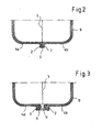
- eine Schnittansicht entlang der Linien II-II in
Figur 1 , - Figur 3:
- eine Schnittansicht entlang der Linien III-III in
Figur 1 , - Figur 4:
- eine vergrößerte Detailansicht der hier in Rede stehenden Durchführung durch den Kraftstoffbehälter,
- Figur 5:
- eine Schnittansicht entlang der Linien V-V in
Figur 4 und - Figur 6:
- eine Schnittansicht entlang der Linien VI-VI in
Figur 4 . - In
Figur 1 ist der Kraftstoffbehälter 1 gemäß der Erfindung stark vereinfacht dargestellt. Dieser wurde durch Extrusionsblasformen von zwei bahnförmigen Extrudaten in einem mehrstufigen Formgebungsprozess hergestellt, und zwar unter Verwendung eines dreiteiligen Werkzeugs mit zwei Außenformen und einer Mittelform. Dabei wurden zunächst zwei bahnförmige Extrudate in der ersten Hitze, d. h. in noch plastischem Zustand und ohne weitere Erwärmung zwischen den Außenformen und der Mittelform platziert. Die Außenformen weisen jeweils Teilkavitäten auf, die der späteren Außenkontur des fertigen Kraftstoffbehälters entsprechen. In einem ersten Schritt werden die Außenformen gegen die Mittelformen geschlossen, wobei jeweils die Vorformlinge zwischen den Außenformen und der Mittelform angeordnet sind. Sodann werden die Vorformlinge innerhalb der Form aufgeweitet und an die Innenflächen der Teilkavitäten der Außenformen angelegt. Über in der Mittelform angeordnete Bauteilhalter oder dergleichen werden innerhalb der so gefertigten Halbschalen des Behälters Einlegeteile angeordnet. Das nachstehend noch zu beschreibende, die Durchführungen aufweisende Einlegeteil kann dabei während der ersten Formgebungsstufe der Halbschalen im Bereich der flanschartig ausgebildeten Ränder derselben platziert worden sein. Sodann werden die Außenformen auseinandergefahren, die Mittelform wird zwischen den Außenformen weggefahren und die Außenformen werden gegeneinander gefahren, sodass die Halbschalen des Kraftstoffbehälters im Bereich ihrer flanschartig umlaufenden Ränder miteinander verschweißen. - Die Halbschalen des Kraftstoffbehälters 1 sind aus einem sechsschichtigen Co-Extrudat mit einer in dieses eingebetteten Barriereschicht für Kohlenwasserstoffe ausgebildet.
- Wie dies aus
Figur 1 ersichtlich ist, besitzt der Kraftstoffbehälter 1 eine umlaufende Naht 3, an der die flanschartig ausgebildeten Ränder 2 der Halbschalen 4a, 4b des Kraftstoffbehälters 1 miteinander verschweißt sind. Der Kraftstoffbehälter 1 ist weiterhin mit einem üblichen Einfüllrohr versehen, welches aus Vereinfachungsgründen in den Figuren nicht dargestellt ist. - Darüber hinaus ist der Kraftstoffbehälter 1 betreffend seine Geometrie stark vereinfacht. Es ist für den Fachmann selbstverständlich, dass der Kraftstoffbehälter 1 eine verhältnismäßig zerklüftete und komplexe Außenstruktur aufweisen kann.
- An dem Kraftstoffbehälter 1 sind in erfindungsgemäßer Art und Weise mehrere Durchführungen 5 vorgesehen, die die Naht 3 des Kraftstoffbehälters so durchsetzen, dass diese eine Schnittstelle des Kraftstoffbehälters 1 bilden. Die Durchführungen 5 sind in einer als Einlegeteil ausgebildeten Multifunktionskupplung 6 angeordnet. Diese Multifunktionskupplung 6 besitzt einen Grundkörper 7 aus thermoplastischem Kunststoff, der bei dem dargestellten Ausführungsbeispiel insgesamt drei Durchführungen 5 und einen elektrischen Steckkontakt 8 aufweist. Es ist für den Fachmann ersichtlich, dass die Multifunktionskupplung 6 eine beliebige Anzahl von elektrischen Steckkontakten 8 bzw. Durchführungen 5 aufweisen kann und dass die Anzahl und Anordnung der Durchführungen 5 sowie elektrischen Steckkontakte 8 einer gewissen Beliebigkeit unterliegt.
- Wie eingangs bereits erwähnt, ist die Multifunktionskupplung 6 als Einlegeteil in die Naht 3 des Kraftstoffbehälters 1 eingefügt und mit der Wandung 9 des Kunststoffbehälters in diesem Bereich verschweißt. Der Grundkörper 7 kann beispielsweise aus Polyethylen oder einem anderen mit der Wandung 9 des Kraftstoffbehälters 1 verschweißbaren Kunststoff bestehen.
- Alternativ kann der Grundkörper 7 der Multifunktionskupplung 6 aus mehreren Kunststoffkomponenten zusammengesetzt sein, wobei vorzugsweise die äußere Umfassung des Grundkörpers 7 aus einem mit der Wandung 9 des Kraftstoffbehälters 1 verschweißbaren Kunststoff besteht, wohingegen der übrige Grundkörper 7 im Bereich der Durchführungen 5 oder im Bereich des elektrischen Steckkontakts aus einem in Anwesenheit von Kraftstoffen nicht quellendem Kunststoff bestehen kann, beispielsweise POM (Polyoxymethylen).
- Wie insbesondere aus den Figuren ersichtlich ist, erstrecken sich die Durchführungen 5 sowie der elektrische Steckkontakt 8 quer zum Verlauf der Naht 3 und in der Trennebene der Halbschalen 4a, 4b.
- Wie der
Figur 6 zu entnehmen ist, können die Durchführungen 5 so ausgebildet sein, dass diese von Belüftungs- und Entlüftungsleitungen vollständig durchsetzt werden. Die Durchführungen können allerdings auch so ausgebildet sein, dass diese Kupplungsfortsätze für anzuschließende Leitungen bilden, beispielsweise mit einem Tannenbaumprofil zum Aufwürgen von flexiblen Leitungen. -
- 1
- Kraftstoffbehälter
- 2
- Ränder
- 3 ·
- Naht
- 4a, 4b
- Halbschalen
- 5
- Durchführungen
- 6
- Multifunktionskupplung
- 7
- Grundkörper
- 8
- elektrischer Steckkontakt
- 9
- Wandung
Claims (6)
- Kraftstoffbehälter (1) aus thermoplastischem Kunststoff mit wenigstens einer umlaufenden, als Schweiß- oder Quetschnaht ausgebildeten Naht (3), mit wenigstens einer Einfüllöffnung, mit Mitteln zur Be- und Entlüftung und mit Mitteln zur Förderung und Entnahme von Kraftstoff zu einer Brennkraftmaschine eines Kfz, wobei der Kraftstoffbehälter (1) wenigstens eine Durchführung (5) für aus diesem herauszuführende Leitungen aufweist, wobei die Durchführung (5) die Naht (3) des Behälters durchsetzt und sich in einem Winkel zum Verlauf der Naht (3) erstreckt, dadurch gekennzeichnet, dass die Durchführung (5) innerhalb eines die Naht (3) durchsetzenden Einlegeteils oder Einsatzes ausgebildet ist.
- Kraftstoffbehälter nach Anspruch 1, dadurch gekennzeichnet, dass die Wandung (9) des Behälters aus einem mehrschichtigen Extrudat mit wenigstens einer Barriereschicht für Kohlenwasserstoffe besteht.
- Kraftstoffbehälter nach einem der Ansprüche 1 oder 2, dadurch gekennzeichnet, dass dieser wenigstens aus zwei Schalen zusammengesetzt ist, die jeweils im Bereich der Naht (3) einen flanschartigen Rand (2) ausbilden.
- Kraftstoffbehälter nach einem der Ansprüche 1 bis 3, dadurch gekennzeichnet, dass sich die Durchführung (5) quer zum Verlauf der Naht (3) und in der Trennebene der Schalen erstreckt.
- Kraftstoffbehälter nach Anspruch 1, dadurch gekennzeichnet, dass das Einlegeteil zumindest teilweise aus Kunststoff besteht und mit dem Kunststoff des Behälters in der Naht (3) verschweißt ist.
- Kraftstoffbehälter nach einem der Ansprüche 1 bis 5, dadurch gekennzeichnet, dass das Einlegeteil als Steckverbinder ausgebildet ist.
Applications Claiming Priority (2)
| Application Number | Priority Date | Filing Date | Title |
|---|---|---|---|
| DE102006031903A DE102006031903A1 (de) | 2006-07-07 | 2006-07-07 | Kraftstoffbehälter |
| PCT/EP2007/005151 WO2008003386A1 (de) | 2006-07-07 | 2007-06-12 | Kraftstoffbehälter |
Publications (2)
| Publication Number | Publication Date |
|---|---|
| EP2038136A1 EP2038136A1 (de) | 2009-03-25 |
| EP2038136B1 true EP2038136B1 (de) | 2011-02-23 |
Family
ID=38441974
Family Applications (1)
| Application Number | Title | Priority Date | Filing Date |
|---|---|---|---|
| EP07725964A Active EP2038136B1 (de) | 2006-07-07 | 2007-06-12 | Kraftstoffbehälter |
Country Status (10)
| Country | Link |
|---|---|
| EP (1) | EP2038136B1 (de) |
| JP (1) | JP5002648B2 (de) |
| KR (1) | KR20090033354A (de) |
| CN (1) | CN101489815B (de) |
| AT (1) | ATE499230T1 (de) |
| BR (1) | BRPI0713553B1 (de) |
| CA (1) | CA2654102C (de) |
| DE (2) | DE102006031903A1 (de) |
| MX (1) | MX2009000168A (de) |
| WO (1) | WO2008003386A1 (de) |
Families Citing this family (15)
| Publication number | Priority date | Publication date | Assignee | Title |
|---|---|---|---|---|
| ATE537960T1 (de) | 2007-06-22 | 2012-01-15 | Kautex Textron Gmbh & Co Kg | Kraftstoffbehälter |
| WO2010006900A1 (en) * | 2008-06-23 | 2010-01-21 | Inergy Automotive Systems Research (Société Anonyme) | Process for manufacturing a fuel tank |
| DE102010025006A1 (de) * | 2010-06-24 | 2011-12-29 | Kautex Textron Gmbh & Co. Kg | Verfahren zur Herstellung von Hohlkörpern aus thermoplastischem Kunststoff sowie Vorrichtung zur Durchführung des Verfahrens |
| US9592729B2 (en) | 2010-11-17 | 2017-03-14 | Aisan Kogyo Kabushiki Kaisha | Fuel tank |
| DE102012000119B4 (de) | 2012-01-05 | 2013-09-12 | Kautex Textron Gmbh & Co. Kg | Flüssigkeitsbehälter für ein Kraftfahrzeug |
| DE102012023172A1 (de) * | 2012-11-28 | 2014-06-12 | Kautex Textron Gmbh & Co. Kg | Instationärer Behälter sowie Verfahren zu dessen Herstellung |
| DE102013004926A1 (de) * | 2013-03-22 | 2014-09-25 | Kautex Textron Gmbh & Co. Kg | Betriebsflüssigkeitbehälter |
| DE102013004929B4 (de) * | 2013-03-22 | 2018-07-12 | Kautex Textron Gmbh & Co. Kg | Betriebsflüssigkeitsbehälter |
| JP6178673B2 (ja) * | 2013-08-29 | 2017-08-09 | 愛三工業株式会社 | 計測装置 |
| DE102014222143B4 (de) * | 2014-10-30 | 2025-01-16 | Volkswagen Aktiengesellschaft | Kraftstoffbehälter für ein Kraftfahrzeug sowie ein Verfahren zur Herstellung des Kraftstoffbehälters |
| DE102015212524B8 (de) * | 2015-07-03 | 2017-04-13 | Kautex Textron Gmbh & Co. Kg | Auftauvorrichtung für Betriebsflüssigkeitsbehälter |
| EP3168075A1 (de) * | 2015-11-16 | 2017-05-17 | Plastic Omnium Advanced Innovation and Research | Tank mit einem steckverbinder und verfahren zum anschliessen einer elektrischen vorrichtung in einem tank |
| CN106828949A (zh) * | 2015-12-07 | 2017-06-13 | Pfw航空航天股份有限公司 | 油箱组件 |
| DE102017222250B4 (de) * | 2017-12-08 | 2023-09-21 | Bayerische Motoren Werke Aktiengesellschaft | Kraftstofftank für ein Kraftfahrzeug, insbesondere für ein Motorrad, sowie Verfahren zum Herstellen eines Kraftstofftanks |
| FR3085631B1 (fr) * | 2018-09-11 | 2022-03-18 | Plastic Omnium Advanced Innovation & Res | Element de connexion electrique pour un reservoir de vehicule automobile |
Family Cites Families (10)
| Publication number | Priority date | Publication date | Assignee | Title |
|---|---|---|---|---|
| JPH0247033A (ja) * | 1988-08-09 | 1990-02-16 | Nissan Motor Co Ltd | ブロー成形法 |
| JP3090373B2 (ja) * | 1992-04-17 | 2000-09-18 | 株式会社ニフコ | 車両用燃料タンク |
| JP3751983B2 (ja) * | 1993-05-31 | 2006-03-08 | 株式会社クラレ | 多層構造体 |
| DE19627742C2 (de) * | 1996-07-10 | 2000-08-03 | Mannesmann Vdo Ag | Kraftstoffbehälter und Verfahren zu seiner Herstellung |
| US6179145B1 (en) * | 1999-12-20 | 2001-01-30 | Delphi Technologies, Inc | Serviceable sealed fuel tank |
| US6712234B2 (en) * | 2000-02-14 | 2004-03-30 | Ti Group Automotive Systems Technology Center Gmbh | Fuel tank and method for its production |
| US7211307B2 (en) | 2002-07-11 | 2007-05-01 | Visteon Global Techologies, Inc. | Low permeation polymer fuel tank |
| JP3822864B2 (ja) * | 2003-03-24 | 2006-09-20 | 八千代工業株式会社 | 燃料タンクのアース構造 |
| JP4596787B2 (ja) * | 2003-04-25 | 2010-12-15 | 豊田合成株式会社 | 燃料タンク |
| DE10339548A1 (de) | 2003-08-26 | 2005-03-31 | Kautex Textron Gmbh & Co. Kg | Verfahren und Vorrichtung zur Kraftstoffversorgung eines wasserstoffbetriebenen Kraftfahrzeugs |
-
2006
- 2006-07-07 DE DE102006031903A patent/DE102006031903A1/de not_active Withdrawn
-
2007
- 2007-06-12 DE DE502007006550T patent/DE502007006550D1/de active Active
- 2007-06-12 BR BRPI0713553-0A patent/BRPI0713553B1/pt active IP Right Grant
- 2007-06-12 EP EP07725964A patent/EP2038136B1/de active Active
- 2007-06-12 MX MX2009000168A patent/MX2009000168A/es active IP Right Grant
- 2007-06-12 CA CA2654102A patent/CA2654102C/en active Active
- 2007-06-12 AT AT07725964T patent/ATE499230T1/de active
- 2007-06-12 JP JP2009518730A patent/JP5002648B2/ja active Active
- 2007-06-12 WO PCT/EP2007/005151 patent/WO2008003386A1/de not_active Ceased
- 2007-06-12 KR KR1020097000303A patent/KR20090033354A/ko not_active Ceased
- 2007-06-12 CN CN2007800256444A patent/CN101489815B/zh not_active Ceased
Also Published As
| Publication number | Publication date |
|---|---|
| DE502007006550D1 (de) | 2011-04-07 |
| KR20090033354A (ko) | 2009-04-02 |
| CA2654102A1 (en) | 2008-01-10 |
| EP2038136A1 (de) | 2009-03-25 |
| MX2009000168A (es) | 2009-01-26 |
| CN101489815A (zh) | 2009-07-22 |
| JP5002648B2 (ja) | 2012-08-15 |
| DE102006031903A1 (de) | 2008-01-10 |
| CA2654102C (en) | 2011-11-22 |
| BRPI0713553A2 (pt) | 2012-03-20 |
| WO2008003386A1 (de) | 2008-01-10 |
| CN101489815B (zh) | 2012-01-11 |
| JP2009542510A (ja) | 2009-12-03 |
| BRPI0713553B1 (pt) | 2019-05-28 |
| ATE499230T1 (de) | 2011-03-15 |
Similar Documents
| Publication | Publication Date | Title |
|---|---|---|
| EP2038136B1 (de) | Kraftstoffbehälter | |
| EP2158103B1 (de) | Kraftstoffbehälter | |
| DE60102887T2 (de) | Behälter mit einem Anschlussstück und Verfahren zur Herstellung desselben | |
| DE10107075B4 (de) | Kraftstoffbehälter und Verfahren zu seiner Herstellung | |
| EP1894702B1 (de) | Verfahren zur Herstellung eines Kraftstoffbehälters | |
| DE10260953B4 (de) | Kraftstoffbehälter mit Funktionsbauteil-Träger sowie Träger für Funktionsbauteile eines KFZ-Kraftstoffbehälters | |
| DE112009001458B4 (de) | Prozess zum Herstellen eines Kraftstoffbehälters | |
| DE10054876C2 (de) | Doppelwandiger Kraftstoffbehälter aus Kunststoff | |
| EP3433120B1 (de) | Betriebsflüssigkeitsbehälter mit versteifungselement und verfahren zum herstellen eines betriebsflüssigkeitsbehälters | |
| EP1084889B1 (de) | Tankeinsatz und Verfahren zu dessen Herstellung | |
| EP3490776B1 (de) | Verfahren zum herstellen eines flüssigkeitsbehälters, flüssigkeitsbehälter für ein kraftfahrzeug und spritzgusswerkzeug | |
| DE102004058228A1 (de) | Kraftstoffsystemkomponente und Verfahren zur Herstellung | |
| EP2030755A1 (de) | Verfahren zur Herstellung eines Stutzens | |
| EP3676069B1 (de) | Spritzgussverfahren und flüssigkeitsbehälter für ein kraftfahrzeug | |
| EP3676080B1 (de) | Flüssigkeitsbehälter und verfahren zum herstellen eines flüssigkeitsbehälters | |
| WO2008071299A1 (de) | Kraftstoffbehälter aus thermoplastischem kunststoff mit funktionseinbauten zur be- und entlüftung, zur kraftstoffentnahme oder dergleichen | |
| DE10214900A1 (de) | Kraftstoffbehälter für Kraftfahrzeuge sowie Verfahren zur Herstellung desselben | |
| EP3259110B1 (de) | Verfahren zum extrusionsblasformen eines behälters aus thermoplastischem kunststoff sowie extrusionsblasgeformter behälter | |
| DE10018310A1 (de) | Kraftstoffbehälter aus Kunststoff und Verfahren zu dessen Herstellung | |
| DE202006021209U1 (de) | Kraftstoffbehälter | |
| DE102012014272A1 (de) | Kraftstoffbehälter aus thermoplastischem Kunststoff sowie Vefahren zu dessen Herstellung | |
| EP3083193B1 (de) | Verfahren zur herstellung eines behälters aus thermoplastischem kunststoff sowie nach dem verfahren hergestellter kunststoffbehälter | |
| DE102014221823A1 (de) | Verfahren zur Herstellung eines Kunststoffkraftstoffbehälters | |
| DE102017128333B3 (de) | Adapter und Verfahren zur Herstellung eines Behälters unter Verwendung des Adapters sowie Behälter mit dem Adapter | |
| DE102006055117A1 (de) | Leitungsanordnung in einem Kunststoffbehälter |
Legal Events
| Date | Code | Title | Description |
|---|---|---|---|
| PUAI | Public reference made under article 153(3) epc to a published international application that has entered the european phase |
Free format text: ORIGINAL CODE: 0009012 |
|
| 17P | Request for examination filed |
Effective date: 20081031 |
|
| AK | Designated contracting states |
Kind code of ref document: A1 Designated state(s): AT BE BG CH CY CZ DE DK EE ES FI FR GB GR HU IE IS IT LI LT LU LV MC MT NL PL PT RO SE SI SK TR |
|
| AX | Request for extension of the european patent |
Extension state: AL BA HR MK RS |
|
| 17Q | First examination report despatched |
Effective date: 20091112 |
|
| GRAP | Despatch of communication of intention to grant a patent |
Free format text: ORIGINAL CODE: EPIDOSNIGR1 |
|
| GRAS | Grant fee paid |
Free format text: ORIGINAL CODE: EPIDOSNIGR3 |
|
| GRAA | (expected) grant |
Free format text: ORIGINAL CODE: 0009210 |
|
| AK | Designated contracting states |
Kind code of ref document: B1 Designated state(s): AT BE BG CH CY CZ DE DK EE ES FI FR GB GR HU IE IS IT LI LT LU LV MC MT NL PL PT RO SE SI SK TR |
|
| REG | Reference to a national code |
Ref country code: GB Ref legal event code: FG4D Free format text: NOT ENGLISH |
|
| REG | Reference to a national code |
Ref country code: CH Ref legal event code: EP Ref country code: RO Ref legal event code: EPE |
|
| REG | Reference to a national code |
Ref country code: IE Ref legal event code: FG4D Free format text: LANGUAGE OF EP DOCUMENT: GERMAN |
|
| REF | Corresponds to: |
Ref document number: 502007006550 Country of ref document: DE Date of ref document: 20110407 Kind code of ref document: P |
|
| REG | Reference to a national code |
Ref country code: DE Ref legal event code: R096 Ref document number: 502007006550 Country of ref document: DE Effective date: 20110407 |
|
| REG | Reference to a national code |
Ref country code: NL Ref legal event code: VDEP Effective date: 20110223 |
|
| LTIE | Lt: invalidation of european patent or patent extension |
Effective date: 20110223 |
|
| PG25 | Lapsed in a contracting state [announced via postgrant information from national office to epo] |
Ref country code: ES Free format text: LAPSE BECAUSE OF FAILURE TO SUBMIT A TRANSLATION OF THE DESCRIPTION OR TO PAY THE FEE WITHIN THE PRESCRIBED TIME-LIMIT Effective date: 20110603 Ref country code: GR Free format text: LAPSE BECAUSE OF FAILURE TO SUBMIT A TRANSLATION OF THE DESCRIPTION OR TO PAY THE FEE WITHIN THE PRESCRIBED TIME-LIMIT Effective date: 20110524 Ref country code: SE Free format text: LAPSE BECAUSE OF FAILURE TO SUBMIT A TRANSLATION OF THE DESCRIPTION OR TO PAY THE FEE WITHIN THE PRESCRIBED TIME-LIMIT Effective date: 20110223 Ref country code: LT Free format text: LAPSE BECAUSE OF FAILURE TO SUBMIT A TRANSLATION OF THE DESCRIPTION OR TO PAY THE FEE WITHIN THE PRESCRIBED TIME-LIMIT Effective date: 20110223 Ref country code: PT Free format text: LAPSE BECAUSE OF FAILURE TO SUBMIT A TRANSLATION OF THE DESCRIPTION OR TO PAY THE FEE WITHIN THE PRESCRIBED TIME-LIMIT Effective date: 20110623 Ref country code: LV Free format text: LAPSE BECAUSE OF FAILURE TO SUBMIT A TRANSLATION OF THE DESCRIPTION OR TO PAY THE FEE WITHIN THE PRESCRIBED TIME-LIMIT Effective date: 20110223 |
|
| PG25 | Lapsed in a contracting state [announced via postgrant information from national office to epo] |
Ref country code: CY Free format text: LAPSE BECAUSE OF FAILURE TO SUBMIT A TRANSLATION OF THE DESCRIPTION OR TO PAY THE FEE WITHIN THE PRESCRIBED TIME-LIMIT Effective date: 20110223 Ref country code: BG Free format text: LAPSE BECAUSE OF FAILURE TO SUBMIT A TRANSLATION OF THE DESCRIPTION OR TO PAY THE FEE WITHIN THE PRESCRIBED TIME-LIMIT Effective date: 20110523 Ref country code: NL Free format text: LAPSE BECAUSE OF FAILURE TO SUBMIT A TRANSLATION OF THE DESCRIPTION OR TO PAY THE FEE WITHIN THE PRESCRIBED TIME-LIMIT Effective date: 20110223 Ref country code: SI Free format text: LAPSE BECAUSE OF FAILURE TO SUBMIT A TRANSLATION OF THE DESCRIPTION OR TO PAY THE FEE WITHIN THE PRESCRIBED TIME-LIMIT Effective date: 20110223 Ref country code: FI Free format text: LAPSE BECAUSE OF FAILURE TO SUBMIT A TRANSLATION OF THE DESCRIPTION OR TO PAY THE FEE WITHIN THE PRESCRIBED TIME-LIMIT Effective date: 20110223 |
|
| REG | Reference to a national code |
Ref country code: IE Ref legal event code: FD4D |
|
| PG25 | Lapsed in a contracting state [announced via postgrant information from national office to epo] |
Ref country code: EE Free format text: LAPSE BECAUSE OF FAILURE TO SUBMIT A TRANSLATION OF THE DESCRIPTION OR TO PAY THE FEE WITHIN THE PRESCRIBED TIME-LIMIT Effective date: 20110223 Ref country code: IE Free format text: LAPSE BECAUSE OF FAILURE TO SUBMIT A TRANSLATION OF THE DESCRIPTION OR TO PAY THE FEE WITHIN THE PRESCRIBED TIME-LIMIT Effective date: 20110223 Ref country code: DK Free format text: LAPSE BECAUSE OF FAILURE TO SUBMIT A TRANSLATION OF THE DESCRIPTION OR TO PAY THE FEE WITHIN THE PRESCRIBED TIME-LIMIT Effective date: 20110223 |
|
| PG25 | Lapsed in a contracting state [announced via postgrant information from national office to epo] |
Ref country code: SK Free format text: LAPSE BECAUSE OF FAILURE TO SUBMIT A TRANSLATION OF THE DESCRIPTION OR TO PAY THE FEE WITHIN THE PRESCRIBED TIME-LIMIT Effective date: 20110223 |
|
| PG25 | Lapsed in a contracting state [announced via postgrant information from national office to epo] |
Ref country code: MT Free format text: LAPSE BECAUSE OF FAILURE TO SUBMIT A TRANSLATION OF THE DESCRIPTION OR TO PAY THE FEE WITHIN THE PRESCRIBED TIME-LIMIT Effective date: 20110223 |
|
| PLBE | No opposition filed within time limit |
Free format text: ORIGINAL CODE: 0009261 |
|
| STAA | Information on the status of an ep patent application or granted ep patent |
Free format text: STATUS: NO OPPOSITION FILED WITHIN TIME LIMIT |
|
| REG | Reference to a national code |
Ref country code: CH Ref legal event code: PL |
|
| 26N | No opposition filed |
Effective date: 20111124 |
|
| PG25 | Lapsed in a contracting state [announced via postgrant information from national office to epo] |
Ref country code: PL Free format text: LAPSE BECAUSE OF FAILURE TO SUBMIT A TRANSLATION OF THE DESCRIPTION OR TO PAY THE FEE WITHIN THE PRESCRIBED TIME-LIMIT Effective date: 20110223 |
|
| REG | Reference to a national code |
Ref country code: DE Ref legal event code: R097 Ref document number: 502007006550 Country of ref document: DE Effective date: 20111124 |
|
| PG25 | Lapsed in a contracting state [announced via postgrant information from national office to epo] |
Ref country code: LI Free format text: LAPSE BECAUSE OF NON-PAYMENT OF DUE FEES Effective date: 20110630 Ref country code: CH Free format text: LAPSE BECAUSE OF NON-PAYMENT OF DUE FEES Effective date: 20110630 |
|
| PG25 | Lapsed in a contracting state [announced via postgrant information from national office to epo] |
Ref country code: IT Free format text: LAPSE BECAUSE OF FAILURE TO SUBMIT A TRANSLATION OF THE DESCRIPTION OR TO PAY THE FEE WITHIN THE PRESCRIBED TIME-LIMIT Effective date: 20110223 |
|
| REG | Reference to a national code |
Ref country code: DE Ref legal event code: R082 Ref document number: 502007006550 Country of ref document: DE Representative=s name: KIERDORF RITSCHEL PATENTANWAELTE PARTG MBB, DE Ref country code: DE Ref legal event code: R082 Ref document number: 502007006550 Country of ref document: DE Representative=s name: KIERDORF RITSCHEL RICHLY PATENTANWAELTE PARTG , DE Ref country code: DE Ref legal event code: R082 Ref document number: 502007006550 Country of ref document: DE Representative=s name: RICHLY & RITSCHEL PATENTANWAELTE PARTG MBB, DE |
|
| PG25 | Lapsed in a contracting state [announced via postgrant information from national office to epo] |
Ref country code: MC Free format text: LAPSE BECAUSE OF NON-PAYMENT OF DUE FEES Effective date: 20110630 |
|
| PG25 | Lapsed in a contracting state [announced via postgrant information from national office to epo] |
Ref country code: LU Free format text: LAPSE BECAUSE OF NON-PAYMENT OF DUE FEES Effective date: 20110612 |
|
| PG25 | Lapsed in a contracting state [announced via postgrant information from national office to epo] |
Ref country code: IS Free format text: LAPSE BECAUSE OF FAILURE TO SUBMIT A TRANSLATION OF THE DESCRIPTION OR TO PAY THE FEE WITHIN THE PRESCRIBED TIME-LIMIT Effective date: 20110223 |
|
| REG | Reference to a national code |
Ref country code: AT Ref legal event code: MM01 Ref document number: 499230 Country of ref document: AT Kind code of ref document: T Effective date: 20120612 |
|
| PG25 | Lapsed in a contracting state [announced via postgrant information from national office to epo] |
Ref country code: TR Free format text: LAPSE BECAUSE OF FAILURE TO SUBMIT A TRANSLATION OF THE DESCRIPTION OR TO PAY THE FEE WITHIN THE PRESCRIBED TIME-LIMIT Effective date: 20110223 |
|
| PG25 | Lapsed in a contracting state [announced via postgrant information from national office to epo] |
Ref country code: AT Free format text: LAPSE BECAUSE OF NON-PAYMENT OF DUE FEES Effective date: 20120612 Ref country code: HU Free format text: LAPSE BECAUSE OF FAILURE TO SUBMIT A TRANSLATION OF THE DESCRIPTION OR TO PAY THE FEE WITHIN THE PRESCRIBED TIME-LIMIT Effective date: 20110223 |
|
| REG | Reference to a national code |
Ref country code: DE Ref legal event code: R082 Ref document number: 502007006550 Country of ref document: DE Representative=s name: KIERDORF RITSCHEL PATENTANWAELTE PARTG MBB, DE Ref country code: DE Ref legal event code: R082 Ref document number: 502007006550 Country of ref document: DE Representative=s name: KIERDORF RITSCHEL RICHLY PATENTANWAELTE PARTG , DE Ref country code: DE Ref legal event code: R082 Ref document number: 502007006550 Country of ref document: DE Representative=s name: RICHLY & RITSCHEL PATENTANWAELTE PARTG MBB, DE |
|
| REG | Reference to a national code |
Ref country code: FR Ref legal event code: PLFP Year of fee payment: 9 |
|
| REG | Reference to a national code |
Ref country code: FR Ref legal event code: PLFP Year of fee payment: 10 |
|
| REG | Reference to a national code |
Ref country code: FR Ref legal event code: PLFP Year of fee payment: 11 |
|
| REG | Reference to a national code |
Ref country code: FR Ref legal event code: PLFP Year of fee payment: 12 |
|
| P01 | Opt-out of the competence of the unified patent court (upc) registered |
Effective date: 20230526 |
|
| PGFP | Annual fee paid to national office [announced via postgrant information from national office to epo] |
Ref country code: DE Payment date: 20250602 Year of fee payment: 19 |
|
| PGFP | Annual fee paid to national office [announced via postgrant information from national office to epo] |
Ref country code: GB Payment date: 20250618 Year of fee payment: 19 |
|
| PGFP | Annual fee paid to national office [announced via postgrant information from national office to epo] |
Ref country code: BE Payment date: 20250618 Year of fee payment: 19 |
|
| PGFP | Annual fee paid to national office [announced via postgrant information from national office to epo] |
Ref country code: FR Payment date: 20250620 Year of fee payment: 19 |
|
| PGFP | Annual fee paid to national office [announced via postgrant information from national office to epo] |
Ref country code: RO Payment date: 20250606 Year of fee payment: 19 |
|
| PGFP | Annual fee paid to national office [announced via postgrant information from national office to epo] |
Ref country code: CZ Payment date: 20250603 Year of fee payment: 19 |