EP2037648A2 - Vorrichtung zur Analyse von digitalen Rundfunkwellen - Google Patents
Vorrichtung zur Analyse von digitalen Rundfunkwellen Download PDFInfo
- Publication number
- EP2037648A2 EP2037648A2 EP08159788A EP08159788A EP2037648A2 EP 2037648 A2 EP2037648 A2 EP 2037648A2 EP 08159788 A EP08159788 A EP 08159788A EP 08159788 A EP08159788 A EP 08159788A EP 2037648 A2 EP2037648 A2 EP 2037648A2
- Authority
- EP
- European Patent Office
- Prior art keywords
- signal
- window position
- digital broadcast
- broadcast wave
- symbol
- Prior art date
- Legal status (The legal status is an assumption and is not a legal conclusion. Google has not performed a legal analysis and makes no representation as to the accuracy of the status listed.)
- Withdrawn
Links
- 238000000034 method Methods 0.000 claims abstract description 52
- 239000000284 extract Substances 0.000 claims abstract description 13
- 238000000605 extraction Methods 0.000 claims description 9
- 238000005259 measurement Methods 0.000 description 21
- 230000000875 corresponding effect Effects 0.000 description 13
- 238000010586 diagram Methods 0.000 description 12
- 230000005540 biological transmission Effects 0.000 description 8
- 239000002131 composite material Substances 0.000 description 5
- 230000003111 delayed effect Effects 0.000 description 4
- 230000007423 decrease Effects 0.000 description 2
- 230000002596 correlated effect Effects 0.000 description 1
- 230000002542 deteriorative effect Effects 0.000 description 1
- 239000000203 mixture Substances 0.000 description 1
Images


Classifications
-
- H—ELECTRICITY
- H04—ELECTRIC COMMUNICATION TECHNIQUE
- H04L—TRANSMISSION OF DIGITAL INFORMATION, e.g. TELEGRAPHIC COMMUNICATION
- H04L27/00—Modulated-carrier systems
- H04L27/26—Systems using multi-frequency codes
- H04L27/2601—Multicarrier modulation systems
- H04L27/2647—Arrangements specific to the receiver only
- H04L27/2655—Synchronisation arrangements
- H04L27/2662—Symbol synchronisation
- H04L27/2665—Fine synchronisation, e.g. by positioning the FFT window
-
- H—ELECTRICITY
- H04—ELECTRIC COMMUNICATION TECHNIQUE
- H04L—TRANSMISSION OF DIGITAL INFORMATION, e.g. TELEGRAPHIC COMMUNICATION
- H04L27/00—Modulated-carrier systems
- H04L27/26—Systems using multi-frequency codes
- H04L27/2601—Multicarrier modulation systems
- H04L27/2647—Arrangements specific to the receiver only
- H04L27/2655—Synchronisation arrangements
- H04L27/2668—Details of algorithms
- H04L27/2681—Details of algorithms characterised by constraints
- H04L27/2688—Resistance to perturbation, e.g. noise, interference or fading
Definitions
- the present invention relates to a technique for accurately and easily analyzing an OFDM (orthogonal frequency division multiplexing) digital broadcast wave used as, for example, a terrestrial digital broadcast wave.
- OFDM orthogonal frequency division multiplexing
- Terrestrial analog broadcasting in a VHF band and a UHF band that is currently used will be completely replaced with terrestrial digital broadcasting until 2011, which has started in some areas since 2003. That is, it is expected that a terrestrial digital broadcasting service will be provided to the entire country until 2011.
- the terrestrial digital broadcasting uses an OFDM radio wave in the UHF band.
- the terrestrial analog broadcasting is replaced with the terrestrial digital broadcasting in an area where a terrestrial analog broadcasting signal in the VHF band is received, it is necessary to check the transmission conditions of a transmission path from a broadcasting station to the receiving area.
- Delay measurement has been known as one of the main measurement items of the transmission conditions.
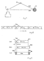
- the delay measurement is performed by detecting the difference between the level and arrival timing of a direct wave A1 that is directly transmitted from a broadcasting station 1 to an area 2 and the level and arrival timing of adelaywaveA2 that is transmitted from the broadcasting station 1 and reflected from a reflector 3 to the area 2.
- characteristics of the difference between the levels and the arrival timings of the signals A1 and A2 are called a delay profile.
- a signal component which is called a guard interval GI, is inserted into each symbol S (i) forming the OFDM signal in a predetermined time width Tg from the head of the symbol.
- the guard interval GI is the same signal component as that with a time width Tg which is at the end of a valid symbol continued to the guard interval. This redundant signal component makes it possible to accurately demodulate data even when a delay wave that is delayed from the direct wave within the range of the time width Tg is received.
- asymbolnon-interference portion Ba in which the signals having the same symbol of the direct wave A1 and the delay wave A2 are synthesized with each other and symbol interference portions Bb in which the signals having different symbols are synthesized with each other appear in turn, in a composite wave B of the two waves.
- a predetermined process can be performed on a signal string in the symbol non-interference portion Ba in which the signals having a strong correlation therebetween are synthesized with each other to accurately calculate a delay profile.
- Fig. 10 is a diagram illustrating aportionof the structure of a digital broadcast wave analyzing apparatus 10 based on the above-mentioned principle.
- the digital broadcast wave analyzing apparatus 10 receives an OFDM signal of a channel to be measured from a signal B0 that is input through, for example, an antenna (not shown) , converts the received signal into a predetermined intermediate frequency band signal B1 using a frequency converting unit 11, and converts the intermediate frequency band signal B1 into a digital signal B2 using an A/D converter 12.
- An orthogonal demodulator 13 performs an orthogonal demodulating process on the digital signal B2, and outputs baseband signals I and Q.
- a symbol timing detecting unit 14 receives the baseband signals I and Q and detects the input timing of a specific position (in this case, the head) of a symbol forming the OFDM signal.
- the window position designating unit 15 designates a value set by the operation of an operating unit 16 as the start timing Ta of a signal extracting process on the symbol, which will be described below, to a window position signal generating unit 17.
- a window position signal generating unit 17 outputs a window position signal W of a predetermined time width Tw after a time Ta has elapsed after a reference timing, which is the input timing of the head of the symbol detected by the symbol timing detecting unit 14, to a signal string extracting unit 18.
- the signal string extracting unit 18 outputs signal strings I' and Q' that are input while receiving the window position signal W from the window position signal generating unit 17, among the signal strings of the input baseband signals I and Q.
- a delay profile generating unit 19 extracts transmission path characteristics from, for example, a payload signal that is included in the symbol using Fourier transform corresponding to the signal strings I' and Q' extracted by the signal string extracting unit 18, and generates a delay profile indicating the difference between the levels and arrival timings of signal components that are included in the input signal B0, which is a measurement target, and are transmitted from the same source through different paths at different timings, using inverse Fourier transform processing to the transmission path characteristics.
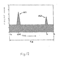
- a display data generating unit 20 generates display data of the waveform of the delayprofile generated by the delayprofile generating unit 19 in the orthogonal coordinate system in which the horizontal axis indicates time and the vertical axis indicates a level, and displays the generated data on a display unit 21 such that the waveform of an incoming wave having the highest level is displayed at a predetermined position.
- the composite wave B is converted into the intermediate frequency band signal B1 ( Fig. 10 ) by the frequency converting unit 11, and the intermediate frequency band signal B1 is converted into the digital signal B2 ( Fig. 10 ) by the A/D converter 12. Then, the digital signal B2 is converted into the baseband signals I and Q by the orthogonal demodulator 13, and the symbol timing detecting unit 14 detects a reference timing t(i) corresponding to a symbol head position, as shown in (a) and (c) of Fig. 11 .
- the detected reference timing is extracted data corresponding to the time width of the guard interval GI. When sliding correlation is performed on the original data, the extracted data used when the largest correlation value is obtained is detected so as to correspond to the head position of the symbol of the direct wave A1 having the highest signal level.
- the window position signal generating unit 17 When the window position designating unit 15 designates the extraction start timing Ta (window position) of the signal string in the reference timing t (i) , the window position signal generating unit 17 generates a window position signal W with a predetermined width Tw (for example, a width corresponding to the length of a valid symbol) after the time Ta has elapsed from the reference timing t(i) , as shown in (d) of Fig. 11 , and outputs the generated signal to the signal string extracting unit 18. Then, as shown in (e) of Fig. 11 , the signal string extracting unit 18 extracts the signal strings T' and Q' while the window position signal W is output, and outputs the signal strings to the delay profile generating unit 19.
- Tw for example, a width corresponding to the length of a valid symbol
- the above process is performed on four continuous symbols S(i) to S(i+3) to obtain signal strings required to accurately extract transmission path characteristics.
- the delay profile generating unit 19 receiving the signal strings generates a delay profile indicating a difference Tx between the levels and arrival timings of the direct wave A1 and the delay wave A2, respectively, as shown in (f) of Fig. 11 .
- the display data generating unit 20 averages data of the delay profile, and the display unit 21 displays the data such that the direct wave A1 having the highest level is displayed at a predetermined position on the time axis.
- the window position Ta is before the delay time Tx
- the head of the extracted signal string is included in the symbol interference portion Bb in which signal components of different symbols are synthesized with each other. Therefore, when the window overlaps with the symbol interference portion Bb, the generation accuracy of the delay profile is lowered, and the noise floor of the displayed delay profile increases.
- SFN single frequency network
- the window position is aligned with the head of the valid symbol of the incoming wave having the highest level in the area where the incoming wave having a low level is received earlier than the incoming wave having a high level
- the next symbol signal overlaps the end of the signal extracted therefrom and a symbol interference portion is generated. As a result, the accuracy of measurement is lowered.
- a measurer operates the operating unit 16 to change the extraction start timing Ta (windowposition) of the signal string to minimize the noise floor of the waveform of the displayed delay profile.
- Ta extraction start timing
- the invention has been made in order to solve the above problems, and an object of the invention is to provide a digital broadcast wave analyzing apparatus capable of rapidly correspond to a variation in multipath characteristics and preventing the measured result from varying depending on a measurer.
- the invention has been made paying attention to the fact that the quality of a broadcast wave including, for example, the noise floor of the waveform of a delay profile corresponds to the modulation accuracy of a received signal, and the above object is attained by setting a window position where the highest modulation error ratio is obtained as an optimum window position for extracting a signal string used for an analysis process.
- a digital broadcast wave analyzing apparatus that receives an OFDM digital broadcast wave, detects a symbol timing from the received signal, extracts signal strings from a signal string of the symbol at predetermined window positions, and performs a process required to analyze the digital broadcast wave on the extracted signal strings.
- the apparatus includes an optimum window position selecting unit 31 that extracts signal strings from a signal string of a symbol for the signal that is received at a specific timing at a plurality of different predetermined window positions, calculates the modulation error ratio of each of the extracted signal strings, and selects a window position where the highest modulation error ratio is obtained as an optimum window position.
- the process required to analyze the digital broadcast wave is performed on the signal string that is extracted from the signal string of the symbol for the signal received at the specific timing at the optimum window position selected by the optimum window position selecting unit.
- the process required to analyze the digital broadcast wave is performed on a signal string that is extracted from a signal string of a symbol for a signal received after the specific timing at the optimum window position selected by the optimum window position selecting unit.
- the optimum window position selecting unit performs the selecting process at the optimum window position, using the timing before the extraction of the signal strings used for the analysis process or the timing after a predetermined time has elapsed during a period for which the signal strings used for the analysis process are continuously extracted at the optimum window position as the specific timing.
- the optimum windowposition selecting unit continuously calculates the modulation error ratio of the signal string extracted at the optimum window position that is selected for the process required to analyze the digital broadcast wave, and selects the optimum window position using the timing when the calculated modulation error ratio is lower than a predetermined reference value as the specific timing.
- a process of calculating a delay profile indicating a difference between the levels and arrival timings of the incoming waves included in the received digital broadcast wave is performed on the signal string that is extracted at the optimum window position selected by the optimum window position selecting unit.
- the digital broadcast wave analyzing apparatus includes the optimum window position selecting unit 31 that extracts signal strings from a signal string of a symbol for the signal that is received at a specific timing at a plurality of different predetermined window positions, calculates the modulation error ratio of each of the extracted signal strings, and selects a window position where the highest modulation error ratio is obtained as an optimum window position.
- timings as the specific timing: the timing before the extraction of the signal strings used for the analysis process; the timing after a predetermined time has elapsed during a period for which the signal strings used for the analysis process are continuously extracted at the optimum window position; or when the modulation error ratio of the signal string extracted at the optimum window position that is selected for the process required to analyze the digital broadcast wave is continuously calculated, the timing when the calculated modulation error ratio is lower than a predetermined reference value.
- a process of calculating a delay profile indicating a difference between the levels and arrival timings of the incoming waves included in the digital broadcast wave is performed on the signal string that is extracted at the optimum window position selectedby the optimumwindowposition selecting unit. According to the above-mentioned structure, it is possible to accurately calculate a delay profile without depending on a measurer and being affected by a variation in multipath characteristics.
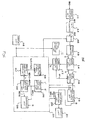
- Fig. 1 is a diagram illustrating the structure of main parts of a digital broadcast wave analyzing apparatus 30 according to an embodiment of the invention
- the digital broadcast wave analyzing apparatus 30 receives an OFDM digital broadcast wave of a desired channel, which is an analysis target, detects symbol timing from the received signal, extracts signal strings from a signal string of the symbol at a designated window position, and performs a calculation required to analyze the digital broadcast wave on the extracted signal strings.
- the digital broadcast wave analyzing apparatus calculates a delay profile indicating a difference between the levels and arrival times of incoming waves included in the digital broadcast wave to be analyzed.
- the digital broadcast wave analyzing apparatus 30 includes a frequency converting unit 11, an A/D converter 12, an orthogonal demodulator 13, a symbol timing detecting unit 14, an operating unit 16, a window position signal generating unit 17, a signal string extracting unit 18, a delay profile generating unit 19, a display data generating unit 20, and a display unit 21, similar to the apparatus 10 according to the related art.
- the frequency converting unit 11 receives a digital broadcast wave of a desired channel from a signal B0 that is input through, for example, an antenna (not shown), converts the signal into a predetermined intermediate frequency band signal B1. Then, the A/D converter 12 converts the intermediate frequency band signal B1 into a digital signal B2 , and the memory 25 temporarily stores the digital signals corresponding to several symbols.
- the orthogonal demodulator 13 performs orthogonal demodulation on the digital signal B2 stored in the memory 25, and outputs baseband signals I and Q.
- the memory 25 may store the signals I and Q output from the orthogonal modulator 13.
- the symbol timing detecting unit 14 receives the baseband signals I and Q and detects the input timing of the head of each symbol forming an OFDM signal, as described above.
- the window position signal generating unit 17 outputs a window position signal W(k) corresponding to a window position Ta (k) that is designated by an optimum window position selecting unit 31, which will be described below, to the signal string extracting unit 18, using the input timing of the head of the symbol detected by the symbol timing detecting unit 14 as a reference timing.
- the signal string extracting unit 18 outputs signal strings I' and Q' that are input while receiving the window position signal W (k) from the window position signal generating unit 18, among the signal strings of the input baseband signals I and Q.
- the delay profile generating unit 19 extracts transmission path characteristics from, for example, a pilot signal that is included in the symbol by Fourier transform corresponding to the signal strings I' and Q' extracted by the signal string extracting unit 18, and generates a delay profile indicating the difference between the levels and arrival timings of the signal components that are included in the input signal B0, which is a measurement target, and are transmitted from the same source through different paths at different timings, using inverse Fourier transform processing to the transmission path characteristics.
- the display data generating unit 20 generates display data of the waveform of the delay profile generated by the delay profile generating unit 19 in the orthogonal coordinate system in which the horizontal axis indicates time and the vertical axis indicates a level, and displays the generated data on the display unit 21 such that the waveform of an incoming wave having the highest level is displayed at a predetermined position.
- the display data generating unit 20 can display a modulation error ratio MER (k) corresponding to the optimum window position selected by the optimum window position selecting unit 31, which will be described below, or a modulation error ratio MER(j) that is obtained during measurement on the display unit 21.
- the digital broadcast wave analyzing apparatus 30 is provided with the optimum window position selecting unit 31 that automatically sets the optimum window position for extracting a signal string used for an analysis process.
- the optimum window position selecting unit 31 includes a windowposition information storage unit 33 , a modulation error ratio calculating unit 35, a modulation error ratio comparing unit 36, an optimum window position storage unit 37, and a determining unit 38.
- a plurality (n number of) of different window positions Ta (1) to Ta (n) are set in the window position information storage unit 33 beforehand.
- the window positions Ta(1) to Ta(n) can be set within the width range of a guard interval GI of a symbol, which is a measurement target, so as to correspond to the length thereof.
- a guard interval GI of a symbol which is a measurement target, so as to correspond to the length thereof.
- the width Tw of each window is equal to the length of a valid symbol.
- the window positions Ta are designated as the window positions Ta.
- the number of window positions and the intervals therebetween are not particularly limited to the above. For example, six or more window positions may be set.
- the previous symbol or the subsequent symbol may overlap the window due to timing deviation (for example, timing mismatch), which results in a significant reduction in measurement accuracy. Therefore, the window position that is aligned with the head of the symbol and the head of the valid symbol may be omitted.
- the optimum window position selecting unit 31 extracts signal strings from the signal string of the symbol detected from the signal B2 (or the signals I and Q) , which has been received at a specific timing and temporarily stored in the memory 25, at a plurality of different window positions Ta(1) to Ta (n) that are stored in the window position information storage unit 33. Then, the modulation error ratio calculating unit 35 calculates the modulation error ratio of each of the extracted signal strings D (1) to D (n) , and the modulation error ratio comparing unit 36 compares the calculated modulation error ratios MER (1) toMER (n). The window position Ta(k) where the highest modulation error ratio MER (k) is obtained is selectedas an optimum window position, and the optimum window position is stored in the optimum window position storage unit 37.
- the specific timingme ans the time when the windowposition is improper due to a variation in multi-paths or whenever a predetermined time has elapsed, in addition to the timing when measurement starts.
- the modulation error ratio MER is a value indicating the modulation quality of a digital modulation signal, and is a value indicating the relationship between a symbol position that is actually detected and a theoretical symbol position on a constellation determined by a modulation method.
- the modulation error ratio MER is calculated by the ratio of carrier power Pc to noise power Pn (Pc/Pn). As the error of the symbol position is reduced, the value of the modulation error ratio MER increases.
- the modulation error ratio is calculated by performing Fourier transform on demodulated data to extract a sub carrier and calculating the power ratio.
- this calculation process has been known (for example, Japanese Unexamined Patent Application Publication No. 2002-124931 ), a detailed description there of will be omitted.
- the modulation error ratio calculating unit 35 continuously calculates the modulation error ratio of a signal string that is extracted from the signal received after a specific timing at the optimum window position Ta(k), and outputs the extracted signal string to the determining unit 38.
- the determining unit 38 determines whether the modulation error ratio calculated by the modulation error ratio calculating unit 35 is lower than a predetermined reference value R.
- selecting unit 31 selects the optimum window position and updates the optimum window position.
- the reference value R be a value depending on the modulation error ratio MER(i) corresponding to the previously selected optimum window position, such as a fixed value determined according to reception environments, a value obtained by subtracting an allowable reduction amount ⁇ r from the modulation error ratio MER(i) corresponding to the previously selected optimum window position, or a value obtained by multiplying the modulation error ratio MER (i) by an allowable reduction rate ⁇ .
- Fig. 2 is a flowchart illustrating the processing sequence of the optimum window position selecting unit 31. The operation of the digital broadcast wave analyzing apparatus 30 will be described below with reference to the flowchart.
- parameters for an OFDM digital broadcast wave for example, a symbol length and a GI length
- the candidates of the optimum window positions, for example, Ta(1) to Ta(5) are determined by the setting (S2).
- signal strings D(1) to D(5) are extracted from the signal string D(0) shown in (a) of Fig. 4 , at the window positions Ta(1) to Ta(5) that are respectively shifted from the signal string D(0) by 0/4, 1/4, 2/4, 3/4, and 4/4 of the width Tg of the guard interval GI, and the modulation error ratio (MER) of each of the signal strings D(1) to D(5) is calculated (S6 to S10).
- MER modulation error ratio
- modulation quality is lowered due to the composition of data having phases and amplitudes that are not correlated with each other, and the value of the modulation error ratio MER decreases.
- the window overlaps with only a symbol non-interference portion Ba the highest modulation quality is obtained, and the highest modulation error ratio MER is obtained.
- the window position Ta(4) where the highest modulation error ratio MER (4) is obtained is stored as the optimum window position (S11) .
- the window position Ta(k) that is selected as the optimum window position is input to the window position signal generating unit 17,
- signal extraction is performed at the window position Ta(k), and a delay profile for the digital broadcast wave is generated.
- the generated delay profile is displayed on the display unit 21 (S12 to S14).
- the optimum window position selecting unit 31 automatically sets the optimum window position for a digital broadcast wave, which is an analysis target, only by setting measurement conditions (for example, a measurement channel and a modulation method) beforehand, and a delay profile for the signal string extracted at the set window position is generated. Then, the delay profile is displayed. Therefore, there is no variation in the result measured by a measurer, and thus it is possible to perform accurate measurement without depending on the measurer.
- measurement conditions for example, a measurement channel and a modulation method
- the digital broadcast wave analyzing apparatus 30 can select a s ingle-shot measurement mode or a continuous measurement mode.
- the digital broadcast wave analyzing apparatus 30 performs signal extraction on the signal string D (0) obtained from the signal B2 that is initially stored in the memory 25 (or the signal string D(0) obtained from the signal B2 that is stored in the memory 25 immediately after the optimum window position is selected) at the optimum window position Ta(k) obtained by the selection process, to calculate a delay profile, and displays the delay profile. Then, the digital broadcast wave analyzing apparatus 30 ends the measuring process.
- the signals B2 stored in the memory 25 are sequentially updated (S31) , and the orthogonal demodulating process and the symbol detecting process are performed on the updated signal (S32). Then, the signal extracting process is sequentially performed on the signal strings obtained by the symbol detecting process at the optimum window position (S12), and the delay profiles of the signal strings obtained by the signal extracting process are sequentially calculated (S13). Then, the display of the delay profile is sequentially updated (S14).
- the optimum window position selecting unit 31 returns to Step S6 whenever a predetermined time has elapsed (S33) to reselect the optimum window position, thereby updating the optimum window position.
- the optimum window position selecting unit 31 continuously calculates the modulation error ratio of the signal string extracted at the optimum window position during the continuous measurement using the modulation error ratio calculating unit 35 (S34) , and compares the calculated modulation error ratio MER(j) with the reference value R (S3S).
- the modulation error ratio MER(j) is less than the reference value R (when the modulation error ratio MER (j) is less than a fixed reference value, or it is more than the modulation error ratio MER (k) corresponding to the previously selected optimum window position)
- the optimum window position selectingunit returns to Step S6 to reselect the optimum window position, thereby updating the optimum window position.
- the process makes it possible to automatically set the optimum window position corresponding to the variation in multipath characteristics, and continuously measure an accurate delay profile without a special operation of the measurer.
- This embodiment performs both the process of updating the optimum window position at a predetermined time interval and the process of updating the optimum window position when the value of the modulation error ratio decreases, but the invention is not limited thereto. Only one of the two update processes may be performed to update the optimum window position.
- one modulation error ratio having the highest level is selected from among the modulation error ratios MER (1) to MER (n) obtained from the signal strings that are extracted at a plurality of window positions Ta (1) to Ta (n) .
- two or more modulation error ratios may have the highest level among the modulation error ratios MER(1) to MER(n).
- the window positions where the highest modulation error ratios MER are obtained may be selected according to a predetermined priority.
- the window position that is distant from the head of the symbol and the head of the valid symbol and is close to an overlap portion of a symbol for an incoming wave having the highest level and a symbol for an incoming wave having the second highest level may be set as the optimum window position such that the measured result does not greatly vary due to little timing deviation.
- a digital broadcast wave analyzing apparatus 30' may be provided with a window position designating unit 15 that provides information of the window position designated by the operation of the operating unit 16 to a window position signal generating unit 17, such that an automatic setting mode that automatically sets the optimum window position and a manual control mode that manually changes the window position can be switched, as described above.
- the modulation error ratio and the bit error ratio (BER) of a digital broadcast wave may be analyzed.
- BER bit error ratio
Landscapes
- Engineering & Computer Science (AREA)
- Computer Networks & Wireless Communication (AREA)
- Signal Processing (AREA)
- Monitoring And Testing Of Transmission In General (AREA)
Applications Claiming Priority (1)
| Application Number | Priority Date | Filing Date | Title |
|---|---|---|---|
| JP2007178959A JP2009017410A (ja) | 2007-07-06 | 2007-07-06 | デジタル放送波評価装置 |
Publications (1)
| Publication Number | Publication Date |
|---|---|
| EP2037648A2 true EP2037648A2 (de) | 2009-03-18 |
Family
ID=40297883
Family Applications (1)
| Application Number | Title | Priority Date | Filing Date |
|---|---|---|---|
| EP08159788A Withdrawn EP2037648A2 (de) | 2007-07-06 | 2008-07-07 | Vorrichtung zur Analyse von digitalen Rundfunkwellen |
Country Status (2)
| Country | Link |
|---|---|
| EP (1) | EP2037648A2 (de) |
| JP (1) | JP2009017410A (de) |
Cited By (1)
| Publication number | Priority date | Publication date | Assignee | Title |
|---|---|---|---|---|
| CN102740494A (zh) * | 2011-04-02 | 2012-10-17 | 上海贝尔股份有限公司 | 一种进行随机接入的方法 |
Citations (2)
| Publication number | Priority date | Publication date | Assignee | Title |
|---|---|---|---|---|
| JP2002124931A (ja) | 2000-10-13 | 2002-04-26 | Anritsu Corp | 変調誤差比測定装置 |
| JP2004236076A (ja) | 2003-01-31 | 2004-08-19 | Toshiba Corp | 受信装置及び受信方法 |
-
2007
- 2007-07-06 JP JP2007178959A patent/JP2009017410A/ja active Pending
-
2008
- 2008-07-07 EP EP08159788A patent/EP2037648A2/de not_active Withdrawn
Patent Citations (2)
| Publication number | Priority date | Publication date | Assignee | Title |
|---|---|---|---|---|
| JP2002124931A (ja) | 2000-10-13 | 2002-04-26 | Anritsu Corp | 変調誤差比測定装置 |
| JP2004236076A (ja) | 2003-01-31 | 2004-08-19 | Toshiba Corp | 受信装置及び受信方法 |
Cited By (2)
| Publication number | Priority date | Publication date | Assignee | Title |
|---|---|---|---|---|
| CN102740494A (zh) * | 2011-04-02 | 2012-10-17 | 上海贝尔股份有限公司 | 一种进行随机接入的方法 |
| US9775175B2 (en) | 2011-04-02 | 2017-09-26 | Alcatel Lucent | Method for random access |
Also Published As
| Publication number | Publication date |
|---|---|
| JP2009017410A (ja) | 2009-01-22 |
Similar Documents
| Publication | Publication Date | Title |
|---|---|---|
| US8576830B2 (en) | Method and system for tracking timing drift in multiple frequency hypothesis testing | |
| US20040141570A1 (en) | Symbol timing correction circuit, receiver, symbol timing correction, mothed, and demodulation processing method | |
| JP5233454B2 (ja) | 移動端末局および受信品質測定方法 | |
| EP2039097B1 (de) | Verfahren und vorrichtung zur schätzung eines trägerfrequenzoffsets | |
| JP5349485B2 (ja) | Cdmaシステムにおける周波数オフセットの推定 | |
| RU2499357C2 (ru) | Приемное устройство, способ приема и приемная система | |
| KR101092557B1 (ko) | 동기신호 검출장치 및 이를 이용한 vsb 수신기 그리고그 방법 | |
| JP3437445B2 (ja) | 線形信号予測を用いた受信装置及び方法 | |
| US6301317B1 (en) | Synchronization system and method for digital communication systems | |
| KR100370590B1 (ko) | 스펙트럼 확산 시스템용 수신장치 | |
| US20090003494A1 (en) | Radio communication system and apparatus | |
| CN101116270A (zh) | 带传送路径推断功能的数字广播接收装置 | |
| CN117060985B (zh) | 一种船载双天线pcma系统信号重捕方法及装置 | |
| EP2037648A2 (de) | Vorrichtung zur Analyse von digitalen Rundfunkwellen | |
| JP5239529B2 (ja) | 同期検出器及び通信機器 | |
| US20060104376A1 (en) | OFDM signal receiver and receiving method | |
| JP3996782B2 (ja) | ダイバーシティ・アダプタおよびダイバーシティ・アダプタからの信号を入力するofdm受信装置ならびにダイバーシティ受信装置 | |
| US8289834B2 (en) | OFDM signal receiving system | |
| JP2004241974A (ja) | シンボル同期回路 | |
| JP4374328B2 (ja) | 遅延測定装置 | |
| US6522686B1 (en) | Receiving apparatus of spectrum spread communication system | |
| JP2003143105A (ja) | Ofdm受信装置および同期獲得方法 | |
| JP3956813B2 (ja) | 無線送信タイミング測定方法およびその方法を実施する装置 | |
| JP3544644B2 (ja) | 無線受信装置及び無線受信装置におけるブランチ間遅延差検出方法 | |
| JP2003332952A (ja) | 線形信号予測を用いた受信装置及び方法 |
Legal Events
| Date | Code | Title | Description |
|---|---|---|---|
| PUAI | Public reference made under article 153(3) epc to a published international application that has entered the european phase |
Free format text: ORIGINAL CODE: 0009012 |
|
| AK | Designated contracting states |
Kind code of ref document: A2 Designated state(s): AT BE BG CH CY CZ DE DK EE ES FI FR GB GR HR HU IE IS IT LI LT LU LV MC MT NL NO PL PT RO SE SI SK TR |
|
| AX | Request for extension of the european patent |
Extension state: AL BA MK RS |
|
| STAA | Information on the status of an ep patent application or granted ep patent |
Free format text: STATUS: THE APPLICATION IS DEEMED TO BE WITHDRAWN |
|
| 18D | Application deemed to be withdrawn |
Effective date: 20150203 |