EP2037339B1 - Verfahren und System zur Steuerung eines Flugzeugs mit einer integrierten Simulation mit Zeitschaltoption - Google Patents
Verfahren und System zur Steuerung eines Flugzeugs mit einer integrierten Simulation mit Zeitschaltoption Download PDFInfo
- Publication number
- EP2037339B1 EP2037339B1 EP08252929.8A EP08252929A EP2037339B1 EP 2037339 B1 EP2037339 B1 EP 2037339B1 EP 08252929 A EP08252929 A EP 08252929A EP 2037339 B1 EP2037339 B1 EP 2037339B1
- Authority
- EP
- European Patent Office
- Prior art keywords
- aircraft
- simulation
- actual environment
- control
- simulation model
- Prior art date
- Legal status (The legal status is an assumption and is not a legal conclusion. Google has not performed a legal analysis and makes no representation as to the accuracy of the status listed.)
- Active
Links
- 238000004088 simulation Methods 0.000 title claims description 220
- 238000000034 method Methods 0.000 title claims description 32
- 230000006870 function Effects 0.000 claims description 24
- 239000000872 buffer Substances 0.000 claims description 18
- 230000033001 locomotion Effects 0.000 claims description 15
- 230000007613 environmental effect Effects 0.000 claims description 7
- 230000009466 transformation Effects 0.000 claims description 4
- 238000004364 calculation method Methods 0.000 description 15
- 238000010586 diagram Methods 0.000 description 12
- 238000004590 computer program Methods 0.000 description 10
- 238000013507 mapping Methods 0.000 description 10
- 238000012545 processing Methods 0.000 description 10
- 230000004044 response Effects 0.000 description 9
- RZVHIXYEVGDQDX-UHFFFAOYSA-N 9,10-anthraquinone Chemical compound C1=CC=C2C(=O)C3=CC=CC=C3C(=O)C2=C1 RZVHIXYEVGDQDX-UHFFFAOYSA-N 0.000 description 6
- 230000001133 acceleration Effects 0.000 description 5
- 230000008901 benefit Effects 0.000 description 5
- 230000008569 process Effects 0.000 description 5
- 241001061260 Emmelichthys struhsakeri Species 0.000 description 4
- 230000009471 action Effects 0.000 description 4
- 230000001934 delay Effects 0.000 description 4
- 230000000694 effects Effects 0.000 description 4
- 230000010355 oscillation Effects 0.000 description 4
- 238000011160 research Methods 0.000 description 4
- 230000008859 change Effects 0.000 description 3
- 238000005094 computer simulation Methods 0.000 description 3
- 230000010354 integration Effects 0.000 description 3
- 238000005259 measurement Methods 0.000 description 3
- 230000003287 optical effect Effects 0.000 description 3
- 230000002829 reductive effect Effects 0.000 description 3
- 230000005540 biological transmission Effects 0.000 description 2
- 238000012937 correction Methods 0.000 description 2
- 230000007423 decrease Effects 0.000 description 2
- 238000012986 modification Methods 0.000 description 2
- 230000004048 modification Effects 0.000 description 2
- 230000006978 adaptation Effects 0.000 description 1
- 230000006399 behavior Effects 0.000 description 1
- 230000009286 beneficial effect Effects 0.000 description 1
- 230000015572 biosynthetic process Effects 0.000 description 1
- 230000015556 catabolic process Effects 0.000 description 1
- 239000012141 concentrate Substances 0.000 description 1
- 230000003247 decreasing effect Effects 0.000 description 1
- 238000006731 degradation reaction Methods 0.000 description 1
- 230000003111 delayed effect Effects 0.000 description 1
- 230000001419 dependent effect Effects 0.000 description 1
- 230000004907 flux Effects 0.000 description 1
- 239000000446 fuel Substances 0.000 description 1
- 230000005484 gravity Effects 0.000 description 1
- 238000003384 imaging method Methods 0.000 description 1
- 238000010348 incorporation Methods 0.000 description 1
- 239000012464 large buffer Substances 0.000 description 1
- 230000000670 limiting effect Effects 0.000 description 1
- 238000004519 manufacturing process Methods 0.000 description 1
- 239000011159 matrix material Substances 0.000 description 1
- 230000001404 mediated effect Effects 0.000 description 1
- 239000013307 optical fiber Substances 0.000 description 1
- 230000009467 reduction Effects 0.000 description 1
- 230000003252 repetitive effect Effects 0.000 description 1
- 230000002441 reversible effect Effects 0.000 description 1
- 238000012552 review Methods 0.000 description 1
- 239000004065 semiconductor Substances 0.000 description 1
- 238000007493 shaping process Methods 0.000 description 1
- 230000003068 static effect Effects 0.000 description 1
- 230000001360 synchronised effect Effects 0.000 description 1
- 238000012360 testing method Methods 0.000 description 1
- 238000012549 training Methods 0.000 description 1
Images

Classifications
-
- G—PHYSICS
- G08—SIGNALLING
- G08G—TRAFFIC CONTROL SYSTEMS
- G08G5/00—Traffic control systems for aircraft, e.g. air-traffic control [ATC]
- G08G5/0047—Navigation or guidance aids for a single aircraft
-
- G—PHYSICS
- G09—EDUCATION; CRYPTOGRAPHY; DISPLAY; ADVERTISING; SEALS
- G09B—EDUCATIONAL OR DEMONSTRATION APPLIANCES; APPLIANCES FOR TEACHING, OR COMMUNICATING WITH, THE BLIND, DEAF OR MUTE; MODELS; PLANETARIA; GLOBES; MAPS; DIAGRAMS
- G09B9/00—Simulators for teaching or training purposes
- G09B9/02—Simulators for teaching or training purposes for teaching control of vehicles or other craft
- G09B9/08—Simulators for teaching or training purposes for teaching control of vehicles or other craft for teaching control of aircraft, e.g. Link trainer
- G09B9/50—Automatically directing the course of the aircraft
-
- G—PHYSICS
- G01—MEASURING; TESTING
- G01C—MEASURING DISTANCES, LEVELS OR BEARINGS; SURVEYING; NAVIGATION; GYROSCOPIC INSTRUMENTS; PHOTOGRAMMETRY OR VIDEOGRAMMETRY
- G01C21/00—Navigation; Navigational instruments not provided for in groups G01C1/00 - G01C19/00
- G01C21/20—Instruments for performing navigational calculations
-
- G—PHYSICS
- G05—CONTROLLING; REGULATING
- G05D—SYSTEMS FOR CONTROLLING OR REGULATING NON-ELECTRIC VARIABLES
- G05D1/00—Control of position, course or altitude of land, water, air, or space vehicles, e.g. automatic pilot
- G05D1/0011—Control of position, course or altitude of land, water, air, or space vehicles, e.g. automatic pilot associated with a remote control arrangement
- G05D1/0044—Control of position, course or altitude of land, water, air, or space vehicles, e.g. automatic pilot associated with a remote control arrangement by providing the operator with a computer generated representation of the environment of the vehicle, e.g. virtual reality, maps
-
- G—PHYSICS
- G08—SIGNALLING
- G08G—TRAFFIC CONTROL SYSTEMS
- G08G5/00—Traffic control systems for aircraft, e.g. air-traffic control [ATC]
- G08G5/0073—Surveillance aids
- G08G5/0078—Surveillance aids for monitoring traffic from the aircraft
-
- G—PHYSICS
- G08—SIGNALLING
- G08G—TRAFFIC CONTROL SYSTEMS
- G08G5/00—Traffic control systems for aircraft, e.g. air-traffic control [ATC]
- G08G5/0073—Surveillance aids
- G08G5/0082—Surveillance aids for monitoring traffic from a ground station
-
- G—PHYSICS
- G08—SIGNALLING
- G08G—TRAFFIC CONTROL SYSTEMS
- G08G5/00—Traffic control systems for aircraft, e.g. air-traffic control [ATC]
- G08G5/04—Anti-collision systems
-
- G—PHYSICS
- G09—EDUCATION; CRYPTOGRAPHY; DISPLAY; ADVERTISING; SEALS
- G09B—EDUCATIONAL OR DEMONSTRATION APPLIANCES; APPLIANCES FOR TEACHING, OR COMMUNICATING WITH, THE BLIND, DEAF OR MUTE; MODELS; PLANETARIA; GLOBES; MAPS; DIAGRAMS
- G09B9/00—Simulators for teaching or training purposes
- G09B9/02—Simulators for teaching or training purposes for teaching control of vehicles or other craft
- G09B9/08—Simulators for teaching or training purposes for teaching control of vehicles or other craft for teaching control of aircraft, e.g. Link trainer
- G09B9/48—Simulators for teaching or training purposes for teaching control of vehicles or other craft for teaching control of aircraft, e.g. Link trainer a model being viewed and manoeuvred from a remote point
-
- B—PERFORMING OPERATIONS; TRANSPORTING
- B64—AIRCRAFT; AVIATION; COSMONAUTICS
- B64U—UNMANNED AERIAL VEHICLES [UAV]; EQUIPMENT THEREFOR
- B64U2201/00—UAVs characterised by their flight controls
- B64U2201/20—Remote controls
Definitions
- the present disclosure relates to remote control of a device, such as an unmanned aerial system (UAS), unmanned aerial vehicle (UAV) or other vehicle or device, and more particularly to a method and system to control operation of a device using an integrated simulation with a time shift option.
- a device such as an unmanned aerial system (UAS), unmanned aerial vehicle (UAV) or other vehicle or device, and more particularly to a method and system to control operation of a device using an integrated simulation with a time shift option.
- Latency One issue with remotely controlling operation of a system or device is latency. This pertains most frequently to system or devices that are at least partly controlled by a remote person or computer. Latency may be defined generally as the period of time between an operator's control input and the operator sensing a system response to the input. Latency tends to limit the rapidity with which control inputs can be made in response to sensor measurements.
- Typical components of the latency may include processing the sensor signal; dwell time of the signal waiting for its spot in the data stream; signal time on route from the remote device or system's transmitter to a base station receiver; signal processing by the base station; possible display of the signal; calculation of the desired control response by the base station computer or operator; processing of this response; dwell time of the response waiting for a slot in the data stream; transmission time between base transmitter and the remote receiver; signal processing by the remote system; and control motion delay.
- latency can reach levels that seriously impede system capability. For instance, in the Mars Rover, latency is on the order of about 20 minutes due to the great distance between the Rover on Mars and the base station on Earth Control of the system by Earth-based operators must be extremely measured and slow in order to make control inputs based on accurate sensor data.
- Latency is to reduce latency in each part of the control system chain.
- reductions may be limited in some situations.
- the simple delay of signals due to the limited speed of light may be a constraint.
- Other latency components may also be difficult to eliminate or reduce.
- Another solution may be to move more of the control system processing tasks onboard the device or vehicle.
- the vehicle is autonomous in its short-term operation and receives controls from a base station less frequently and controls that are more general in nature.
- moving control system processing tasks onboard could mean placing a human operator onboard or within the system.
- One disadvantage to this arrangement is possible exposure of the operator to potential hazards.
- Another disadvantage is that provisions for an onboard human operator may increase the complexity, weight and cost of the system.
- moving increasing control authority from the base station to the remote system with a non-human operator reduces the extent to which the overall system is controllable by a human.
- One drawback to this is that the system may "decide" to take an action that a human operator might decline to make for one reason or another.
- Another possible solution for latency may be operating in a repetitive move-wait cycle.
- the means of controlling operation is used for some commands for unmanned space vehicles, such as the Mars Rover.
- Using a slow move-wait cycle may reduce the productivity of the system because the system cannot perform during the "wait" portion of the cycle.
- Such a method of control may also mean that the system must be designed in such a way that it is stable (if not stationary) during the wait portion of the cycle. This additional constraint on the system may impose penalties on weight, complexity or cost.
- an unmanned aerial vehicle may fly as close as possible to the ground at a high rate of speed.
- Such operation is sometimes referred to as "terrain following".
- Terrain following becomes difficult over variable or hilly terrain.
- the minimum altitude at which the vehicle can fly is limited in part by the vehicle's ability to accelerate vertically (up and down) via elevator control inputs. All air vehicles are limited in this regard.
- Another limitation on altitude is the ability of the remotely located operator or control system to judge the correct point to pull up to avoid a mountain or push down to dive into a valley.
- a small delay in pulling up may result in an inevitable collision with the mountain. Pushing into a valley slightly too soon may also result in a collision. Further, in ideal, calm or still conditions an optimal path may possibly be calculated in advance of an actual flight. In practice, however, there may be variations in conditions during the actual flight that cannot be foreseen or precisely predicted. These variations may include wind, differences in wind direction, turbulence, updrafts and downdrafts. Further unforeseen conditions may include new obstacles, such as towers, power lines or the other obstacles or hazards. The uncertainty in conditions may be dependent in part on the period of time between the latest measurements or observations and the actual operation or flight, the longer the period, the greater the uncertainty.
- margin of safety permits the continued safe operation of the system in the event of an operator error or an unforeseen condition.
- the margin of safety may be statistically determined to reduce errors to an acceptable level.
- a margin of safety generally imposes an operational penalty with respect to one or more measures of merit.
- Another method to reduce operator error may be to replace human operators with computers.
- this may not be without its drawbacks.
- the software to operate complex systems autonomously is complex and expensive, especially when the system must be very reliable.
- human operators are generally considered to be more flexible and resilient in the face of unforeseen circumstances and more competent to make extremely important decisions under complex circumstances.
- US 5,706,195 relates to an enhanced reality maintenance system operating one or more remotely operated vehicles (ROVs) in a hazardous or inaccessible environment.
- a computer model of the environment is created from spatial parameters provided to the system. Positions and orientations of moving objects are monitored. The projected course of the moving objects is extrapolated and constantly updated.
- An automated flight planner receives desired destinations from an operator, analyzes the environment, the projected courses of moving objects and planned trajectories of other ROVs, and selects a planned trajectory of a selected ROV through the environment without collision.
- Rudzinska K. et al. "An interactive system for mobile robot navigation" Robot Motion and Control, 2005 proceedings of the fifth international workshop on. Dymaczewo, Tru, June 23 - 25, 2005, Piscataway, NJ : IEEE, US, 23 June 2005 (2005-06-23), pages 343-348 relates to an interactive system for mobile robot navigation where a real robot in the actual world is controlled using a virtual robot in a 3D reconstruction of the same environment.
- the present disclosure may be embodied as a method, system, or computer program product. Accordingly, portions of the present disclosure may take the form of an entirely hardware embodiment, an entirely software embodiment (including firmware, resident software, microcode, etc.) or an embodiment combining software and hardware aspects that may all generally be referred to herein as a "circuit,” “module,” “unit,” or “system.” Furthermore, the present disclosure may take the form of a computer program product on a computer-usable storage medium having computer-usable program code embodied in the medium.
- the computer-usable or computer-readable medium may be, for example but not limited to, an electronic, magnetic, optical, electromagnetic, infrared, or semiconductor system, apparatus, device, or propagation medium. More specific examples (a non-exhaustive list) of the computer-readable medium would include the following: an electrical connection having one or more wires, a tangible medium such as a portable computer diskette, a hard disk, a random access memory (RAM), a read-only memory (ROM), an erasable programmable read-only memory (EPROM or Flash memory), an optical fiber, a portable compact disc read-only memory (CD-ROM), or other tangible optical or magnetic storage devices; or transmission media such as those supporting the Internet or an intranet.
- a tangible medium such as a portable computer diskette, a hard disk, a random access memory (RAM), a read-only memory (ROM), an erasable programmable read-only memory (EPROM or Flash memory
- an optical fiber such as those supporting the Internet or an intranet.
- CD-ROM compact disc read
- the computer-usable or computer-readable medium could even be paper or another suitable medium upon which the program is printed, as the program can be electronically captured, via, for instance, optical scanning of the paper or other medium, then compiled, interpreted, or otherwise processed in a suitable manner, if necessary, and then stored in a computer memory.
- a computer-usable or computer-readable medium may be any medium that can contain, store, communicate, propagate, or transport the program for use by or in connection with the instruction execution system, apparatus, or device.
- Computer program code for carrying out operations of the present disclosure may be written in an object oriented programming language such as Java, Smalltalk, C++ or the like. However, the computer program code for carrying out operations of the present disclosure may also be written in conventional procedural programming languages, such as the "C" programming language or similar programming languages.
- the program code may execute entirely on the user's computer, partly on the user's computer, as a stand-alone software package, partly on the user's computer and partly on a remote computer or entirely on the remote computer or server.
- the remote computer may be connected to the user's computer through a local area network (LAN) or a wide area network (WAN), or the connection may be made to an external computer (for example, through the Internet using an Internet Service Provider).
- LAN local area network
- WAN wide area network
- Internet Service Provider for example, AT&T, MCI, Sprint, EarthLink, MSN, GTE, etc.
- These computer program instructions may also be stored in a computer-readable memory that can direct a computer or other programmable data processing apparatus to function in a particular manner, such that the instructions stored in the computer-readable memory produce an article of manufacture including instruction means which implement the function/act specified in the flowchart and/or block diagram block or blocks.
- the computer program instructions may also be loaded onto a computer or other programmable data processing apparatus to cause a series of operational steps to be performed on the computer or other programmable apparatus to produce a computer implemented process such that the instructions which execute on the computer or other programmable apparatus provide steps for implementing the functions/acts specified in the flowchart and/or block diagram block or blocks.
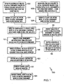
- Figure 1 is a flow chart of an exemplary method 100 to control operation of a device using an integrated simulation with a time delay option in accordance with an embodiment of the present disclosure.
- the device may be an unmanned aerial system (UAS) or vehicle (UAV) or other aerospace vehicle, a terrestrial vehicle, such as the Mars Rover, Lunar Rover, other vehicle useable on Earth, a watercraft, unmanned submersible vehicle, or any type of machine, factory, machine in a factory, or system.
- UAS unmanned aerial system
- UAV vehicle
- a terrestrial vehicle such as the Mars Rover, Lunar Rover, other vehicle useable on Earth
- a watercraft unmanned submersible vehicle, or any type of machine, factory, machine in a factory, or system.
- pre-existing data or information related to actual mission or operating environment or context in which the device is or may be operating may be obtained.
- Examples of the pre-existing data may include photographs or imagery of the actual environment or context; terrain contours; weather predictions; descriptions, locations and other information related to any targets or points of interest in the environment or context; descriptions, locations and other information related to any threats or hazards for the device in the environment; or any other data related to the environment or context of operation that may be of interest.
- the pre-existing data may be obtained by a satellite or a satellite system, aerial and/or ground reconnaissance, fixed locations, sensors associated with any of the preceding or other means.
- At least one virtual model of the actual operating environment may be generated or formed based on the pre-existing data.
- real-time data or information related to the actual operating or mission environment or context may be obtained.
- Examples of the real-time data or information may also include photographs or imagery of the actual environment or context; terrain contours; weather predictions; descriptions, locations and other information related to any targets or points of interest in the environment or context; descriptions, locations and other information related to any threats or hazards for the device in the environment; or any other data related to the environment or context of operation that may be of interest.
- the real-time data may also be obtained by a satellite or satellite system, aerial and/or ground reconnaissance, fixed locations, sensors associated with any of the preceding, or other means.
- At least one virtual model of the actual mission environment or context may be formed or generated based in the real-time data.
- the virtual models may be merged or combined to produce or form an integrated simulation model of the actual operational environment, mission environment or context in which the device is or will be operating.
- software or programs that may be used to model an operational environment may include Google Earth as provided by Google of Mountain View, California; Global-Scenery or X-Scenery, both provided by Laminar Research of Columbia, SC or similar software applications.
- Google Earth as provided by Google of Mountain View, California
- Global-Scenery or X-Scenery both provided by Laminar Research of Columbia, SC or similar software applications.
- Accurate three-dimensional computer models based on multiple photographs may be produced using software such as PhotoModeler available from EOS Systems, Inc. of Vancouver BC, Canada, or similar software or programs.
- Google is a trademark of Google, Inc. in the United States, other countries or both.
- Global-Scenery and X-Scenery are trademarks of Laminar Research in the United States, other countries or both, and PhotoModeler is a trademark of EOS System, Inc. in the United States, Canada and other countries.
- the integrated simulation model may be continually updated based on the real-time data or other data.
- Atmospheric and/or weather conditions can also be measured or determined using various instruments and incorporated into the integrated simulation model of the actual environment.
- motion of the atmosphere can be measured from a distance using laser-based sensors or similar sensors.
- Conditions in an operational environment or context may also be measured or determined using various types of electromagnetic sensors, such as radar, microwave, infrared and light sensors. Data from these sensors can be processed in numerous ways to concentrate on different kinds or types of information. For instance, a shift in frequency may be interpreted as motion by a target or other device according to the Doppler principle.
- a simulation may be generated or created including a representation of the actual device operable in the integrated simulation model of the actual environment.
- the simulation including the representation of the device operating in the simulation model of the actual environment may be presented to an operator to permit control of operation of the simulation and the representation of the actual device in the integrated simulation model of the actual environment.
- the simulation may be controlled along with operation of the simulated device in the integrated simulation model.
- various features of the simulation may be controlled by an operator, such as a flight path or route of travel of the device, a speed of the device or simulation, a time delay option, a re-do option, different viewpoints from which to observe operation of the device in the simulation.
- the time delay option provides a predetermined time period between performing operations in the simulation and having the device in the actual environment perform the same or related operations.
- the time delay may be adjusted to permit more time for critical maneuvers or important aspects of the mission and more time for decision making.
- the simulation may be sped up during lighter workloads and to increase the time delay.
- the time delay may also allow for correction of any mistakes or re-doing a selected operation or function in the simulation before the actual device does the operation.
- Flight simulators are now used to train pilots. Flight simulators generally use a replica airplane cockpit with video screen views through the cockpit transparencies and actual inputs. The flight characteristics of the airplane as well as the external environment may be modeled in a computer. Simulations of real missions can be "flown" for training purposes. Lesser flight simulators are also common now, such as X-Plane by Laminar Research and Microsoft Flight Simulator to name a few. The X-Plane simulator incorporates external views and the instrument panel on a single computer screen and can be operated with a single keyboard and joystick. Simulation of many other systems is also available.
- the control inputs by an operator in the simulation may be passed on to the actual device with a time delay.
- the time delay may be adjustable by the operator to provide an opportunity to "pause” or “rewind” the simulation.
- the operator may pause the simulation to consider options or to aid comprehension during a period that presents too much information.
- the operator may conclude that a mistake may have been made or that performance of a certain function may be improved.
- the operator may "rewind" the simulation by a certain time period in order to "re-do" the operation and correct the error or improve performance. It should be noted that the rewind period must not exceed the time delay between the simulation and performance of the simulated operation of the actual device.
- the adjustable time delay and re-do option may be managed to remain ahead or at least coincident with the actual device operation in the actual operational environment.
- a warning may be issued if the rewind option exceeds the time delay or the rewind will only be permitted to the extent of the time delay with some time margin to insure the control signals are sent before the actual device has to perform the maneuver.
- a pause or rewind will reduce the time delay. If the operator wishes to restore the prior time delay, he can run the simulation at increased speed ("fast forward") until the desired delay is reached. In this case, the delay between the operator's control input and transmitting the control signals to the device must be adjusted so that time runs at constant speed for the actual device.
- the optimum time delay may depend in part on how dynamic the operational environment may be. In a static environment, a long delay can be used. In an extremely dynamic environment, the time delay can be eliminated (or minimized if some latency is unavoidable). In some cases, the optimum delay will be some intermediate length of time.
- the simulated capabilities of the device may be set up to exceed the actual capabilities of the device.
- the simulated device may be operated with altered or enhanced performance characteristics compared to the actual device to more efficiently or effectively perform some operations or functions in the simulation.
- an airplane might have the capability to accelerate vertically at 10 times the force due to gravity or 10 g's. This limits, for instance, the degree to which airplane can follow the contour of hilly terrain.
- the simulation could, on the other hand, have the capability to pull, for example, 20 g's. In the simulated mission, the operator could fly a path attempting to limit acceleration to 10 g's.
- any necessary compensation may be performed based on the operating limitations of the actual device so that the actual device can more efficiently and effectively perform the simulated operations in actuality.
- a control script may be generated based on the simulation.
- the control script may be transmitted to the actual device to control operation of the device in the actual environment.
- the control script may be continuously generated while controlling operation of the simulation of the device in the integrated simulation model of the actual environment.
- the control script may then be streamed to the actual device.
- the data may be sent as a substantially continuous flow of data directly to the actual device.
- the control script may be streamed to the actual device after a predetermined time delay so that the actual device performs the function some predetermined time period after the function is performed in the simulation.
- the variability of the actual device performance compared to the precise and repeatable behavior of some simulations may also be managed by an embodiment of the present disclosure. For instance, a pre-scripted series of control surface deflections could result in a certain flight path for an aircraft on one flight, and quite a different flight path on a subsequent flight due to small variations in atmospheric conditions or other minor variables. These variation can be addressed by controlling the desired flight path (in space and time) and permitting the aircraft's flight control system to manipulate the control surfaces to maintain that path as directed by the simulation. Deviation between the aircraft's commanded and actual path can provide the control system with information about the aircraft's capability on a particular day in a particular set of conditions. This information can also be relayed to the operator who may adjust the mission to account for the aircraft's actual capability in the actual environment.
- real-time data may be integrated into an existing computer model of the environment and representation the device. This permits consideration of dynamic events and conditions in operating the actual device.
- An optimal time delay may balance the benefit of real-time environmental and operating information with the benefit of re-doing some operations and/or modifying flight paths or other operational modifications.
- the adjustable time delay allows for a dynamic response to variations in environmental uncertainty.
- An example of this integration capability may be the integration of radar data taken from the actual device or aircraft being processed to conform to the geometry used for the simulation. This data could be filtered to show new data that is not present on the baseline geometry. For instance, the deployment of obstacles, such as barrage balloons could be detected by radar and displayed in the simulation. In this example, the actual aircraft must not be so far behind the simulation (in space) that the radar (or other sensors) can't see areas of interest to the simulation.
- the simulation can be used to reduce operator time to execute a mission compared to the actual time of the mission.
- the simulation can be run at a higher speed so that the duration of the simulated mission is reduced.
- the playback of the simulation to control the actual device operation the playback is made at the correct or normal speed. Note that in this mode the actual mission may start at the same time as the simulated mission.
- the system can be used to increase operator precision by slowing down time in the simulation so that the operator has increased time to make adjustments to the operation, thereby increasing precision or enabling more thoroughly considered decisions.
- the simulation must start before the real mission at such a time that at the end of the mission the simulation is even with or ahead of the actual mission.
- Figure 2 is a block schematic diagram of an example of a system 200 to control operation of a device using an integrated simulation with a time delay option in accordance with an embodiment of the present disclosure.
- the method 100 may be embodied in or performed by the system 200.
- the device illustrated in Figure 2 that is being controlled is an aircraft 202, such as a UAS, UAV or the like, and the embodiment of the present disclosure illustrated in Figure 2 will be described with respect to controlling the operation of the airplane or aircraft 202; however, the present disclosure may be adapted to control any sort of vehicle, machine or system.
- the system 200 may include an image processor 204 to form an integrated simulation model 206 of an actual operational environment 208 or context in which the device or aircraft 202 is or will be operating. Similar to that previously discussed, the integrated simulation environment model 206 may be formed using pre-existing data or information related to the actual environment 208 and real-time data related to the actual environment 206.
- the image processor 204 may be coupled to a transceiver (Tx/Rx) 210.
- the transceiver 210 may receive pre-existing and/or real-time or current data related to the actual environment 208 from the actual aircraft 202 and from a satellite 21 2 or satellite system including multiple satellites.
- the transceiver 210 may also receive pre-existing and real-time data related to the environment 208 from other movable devices, such as other vehicles (airborne and terrestrial), or from fixed locations.
- the aircraft 202, other devices or vehicles, and fixed locations may include sensors to detect certain characteristics related to the environment as described in more detail herein, such as geographic data, threat and target information, and atmospheric and weather conditions and any other conditions or information that may be of interest or importance to the mission.
- the transceiver 210 may also receive data from the aircraft 202 related to operation of the aircraft 202, such as geographic location, speed, altitude, flight path, status of vehicle systems and any other data or information that may be of interest depending upon the mission.
- the aircraft 202 may include a global positioning system (GPS) receiver that can provide latitude, longitude and altitude information that may be transmitted by the aircraft 202 to the transceiver 210 of the system 200.
- GPS global positioning system
- Another accurate positioning system may be used may be an inertial guidance system based on three-axis acceleration plus angular information derived from gyroscopic sensors as is known and commonly used in navigation.
- the image processor 204 may include a geometric transformation module 214 and an overlay control module 216.
- the transformation module 214 may transform the data received by the transceiver 210 for use in forming the integrated simulation model 206 of the actual environment 208.
- the overlay control module 216 may properly align or overlay different virtual models or images of the actual operational environment 208 generated from the pre-existing and real-time data related to the actual environment 208 to form the integrated simulation model 206 of the actual environment for presentation on a display 225.
- the overlay control module 216 may perform a mapping function. Mapping of images pertains to transformation of two and three dimensional information from one shape to another.
- a camera is an example of one device that may be used to map images.
- a camera provides a viewpoint (the lens node) and an image plane (generally flat). Points in the external world are projected through the viewpoint onto the image plane. The exact results of the mapping depend on the orientation of the camera, the size of the image plane with respect to the distance from the image plane to the viewpoint (focal length) and a number of other factors.
- a camera can map any three dimensional array within its field of view onto its image plane.
- mapping pertains to the re-shaping of images to represent the same image as seen from a different viewpoint.
- An example of this is seen on some roadways in which words (such as "stop") are painted in text that appears to be very elongated when seen from above but appear normal from the viewpoint of a driver.
- Another example is a satellite photograph of a portion of the earth's surface. This image is taken from such a high viewpoint that it is nearly a vertical projection. This image can be mapped (or distorted) to appear geometrically correct from another viewpoint. If the surface of the earth is represented non-planar and its geometry is known, the satellite image can be mapped to appear geometrically correct from any viewpoint.
- Google Earth program Google Earth program, previously discussed, that provides a three-dimensional view of the surface of the earth from any arbitrary location and angle with satellite imagery mapped to the contoured geometry of the earth.
- Examples of other devices that may be used for mapping in addition to cameras may include radar, lidar, sonar, and microwave radar.
- Other devices, such as parabolic microphones may be capable of determining the relative angle of point sources of energy or reflection of energy.
- Three dimensional (3-D) mapping is a more complex form of mapping that is also possible.
- Three dimensional mapping can be done in several ways.
- One method may use a scanning laser rangefinder. This laser rangefinder scans a field of view over a range of lateral and vertical angles with a pulsed laser. By measuring the time between the output of the pulse and its return, the device computes the distance to any external objects. The device compiles this information for a matrix of points and from this "point cloud" a three dimensional surface geometry may be computed.
- Another method of three dimensional mapping uses multiple images from one or more cameras. These images may be used as an enhanced version of stereoscopic imaging to calculate an accurate geometry of an object.
- the geometry of common points in multiple images (from multiple viewpoints) of an object may be analyzed to determine the 3-D geometry of the object. If the viewpoint location, angle and field of view of at least one of the images are known, the location and scale of the 3-D geometry can be calculated. It is advantageous to have the multiple images taken from viewpoints that are not collinear with respect to the object or subject. It is also desirable to have the viewpoints not be coplanar where the plane intersects the object or subject. Additionally, having widely different viewpoints provides differences in views that are substantial and increases the accuracy of any computations.
- Photosynth provided by Microsoft Live Labs.
- Microsoft and Photosynth are trademarks of the Microsoft Corporation of Redmond, Washington.
- Photosynth can take a large collection of photos of a place or object and analyze them for similarities. The photos may then be displayed in a re-constructed three-dimensional space.
- Photosynth a user can virtually walk or fly through a scene to view the place or object from any angle using the photos.
- a photo can be seamlessly zoomed in or out.
- the image processor 204 may also include a symbology module 218 and a tracking control module 220.
- the symbology module 218 may assign or associate predetermined symbols to represent or identify different landmarks or features in the actual environment 208 in the integrated simulation module 206.
- the tracking control module 220 may track any movement of the aircraft 202 in the actual environment 208 to track movement of a representation 221 of the actual aircraft 202 in the simulation 222.
- An environment simulation module 224 may be associated with the image processor 204 to aid in forming the integrated simulation model 206 of the actual environment for presentation on a display 225.
- the environment simulation module 224 may include a geographic database 226, a threat and target database 228, an imagery database 230, and a weather database 231 or module to more accurately simulate weather conditions in the simulation 222 based on real-time data from the actual environment 208.
- the geographic database 226 may store any pre-existing geographic data related to the actual environment 208.
- the geographic data may be obtained from surveys, photographs, terrain contour maps, or other sources similar to those previously described.
- the threat and target database 228 may store any pre-existing data related to potential threats or hazards to the actual aircraft 202 within the actual environment 208 for representation in the integrated simulation model 206.
- the threat and target database 228 may also store any pre-existing data related to targets or points of interest within the actual environment 208 for representation within the integrated simulation model 206.
- the imagery database 230 may store any pre-existing data corresponding to any images related to the actual environment 208. As previously discussed, images may be collected by the satellite 212, the actual aircraft 202, or other devices.
- Threats and targets may be dynamic. That is, they may tend to change character and location over time. Depending on their nature, the characteristic time period may be days, hours, minutes or seconds. Additionally, the terrain or geographic database 226 and imagery database 230 on which the simulation is based may be weeks, months or years old. Accordingly, updating the simulation 222 with real-time data or at least more current data may be beneficial. Updating the data may permit avoidance of new obstacles or possible threats. In the operation of unmanned vehicles, there may be a great distance between the operator and the vehicle or device being controlled resulting in an inherent control loop lag. Updating the environmental data may enhance an operator's ability to respond to dynamic changes, such as movement of threats or targets, within the actual environment 208.
- the real-time or current data may come from numerous sources and may be presented to the operator 234 in numerous ways but needs to be presented in an integrated, easily understandable way with other data, such as pre-existing data.
- the real-time images may be overlaid on the 3-D terrain or geographic data in the geographic database 226. This function may be performed in or controlled by the overlay control module 216. Similar to that previously described, the real-time images could come from one or more overhead satellites, reconnaissance airplanes, or ground-based cameras or sensors. Alternatively or in addition, the images could come from the actual airplane 202. These images can be mapped onto the terrain simulation as described above and then presented in the simulation from a desired viewpoint, such as viewpoint 236.
- a 3-D terrain model can be created with the images wrapping the terrain in the simulation on the fly.
- the terrain model can be created using a 3-D terrain modeling software application, such as Photosynth, as described above, or another terrain modeling software package.
- the terrain can be wrapped using a process similar to Google Earth described above.
- the cameras to create the 3-D terrain model can be located on one or more satellites, reconnaissance airplanes or ground locations. Alternatively or additionally, a camera may be mounted to the actual airplane 202 using its motion to provide the multiple viewpoints needed to calculate the 3-D simulation model. Formation of a real-time 3-D terrain model has the advantage of identifying any new man-made structures.
- Another advantage of creating real-time 3-D terrain models is that in some situations the geometry of the terrain may be completely unknown in advance.
- An example of this is the operation from Earth of an unmanned rover on a rocky and complex surface of a planet, such as Mars.
- the methods described above for the creation of 3-D models can be used to model the region around the rover.
- These models can then be used in the simulated operation, as described herein, and the script from the simulation can be used to operate the actual rover.
- An advantage of this arrangement is to avoid the exceptionally long control loop time created by the limited speed of light over the great distance between the Earth and Mars or another celestial body.
- threats, targets and other features may be enhanced or otherwise highlighted or identified for easy recognition by the operator 234. These may be highlighted with the use of color, brightness, or graphic symbols. These may be presented to the operator 234 or perhaps to a support operator (block 246) as described herein on a display. Some of these features may be identified by a support operator who may control or modify the main operator's display 225.
- the environmental simulation module 224 may include a weather database 231 or module to more accurately simulate the current actual weather or atmospheric conditions in the actual environment 208.
- wind speed and direction can be estimated by comparing measured airspeed and airplane heading with the airplane's ground speed and track. Airspeed and heading can be determined from the airplane's airspeeds sensor and its compass, respectively. Ground speed and track can be measured by GPS or inertial systems, similar to that previously described. This information can then be sent from the airplane 202 to the transceiver 210 for integration into the simulation 206 by the system 200.
- Current or real-time turbulence levels may be measured with accelerometers or other sensors that measure linear and angular accelerations on all three axes. These values can be used to drive simulation turbulence model parameters so that the simulated airplane experiences accelerations of the same magnitude and character as the actual airplane 202.
- the weather module 231 may process the real-time turbulence levels to substantially simulate the effects of the turbulence in the simulation 222.
- the accelerometers or other sensors may be associated with the actual airplane 202, or other air or ground reconnaissance vehicles or fixed position locations.
- the system 200 may also include a control interface 232 including control devices to allow an operator 234 to control operation of the simulation 222 including the representation 221 of the actual aircraft 202 in the integrated simulation model 206 of the actual environment 208.
- the control interface 232 may include control devices or means to control a flight path of the representation of the aircraft 202 in the integrated simulation model 206; a speed of the simulation and/or a speed of the representation 221 of the aircraft; time delay of the simulation 222; device systems or flight vehicle systems; and characteristics of the simulation of the aircraft 202.
- the simulation 222 may be operated a predetermined time period before the aircraft 202 in the actual environment 208.
- the actual operation of the aircraft 202 may be time delayed by a predetermined time period to permit critical portions of the flight to be simulated at a slower speed for more precise maneuvering or decision making, or to permit selected operations or functions to be re-done.
- the simulation 222 may actually be operating in advance of the aircraft 202 in the actual operating environment 208 as illustrated by the phantom aircraft 235 in Figure 2 .
- Phantom aircraft 235 illustrates the time frame of the representation 221 of the device in the simulation 222 compared to the actual aircraft 202 in the actual environment 208.
- the operator control interface 232 may also control the viewpoint 236 from which the simulation 222 is observed.
- viewpoints 236 may include a viewpoint from within the representation 221 of the aircraft in the simulation 222; a viewpoint outside of the representation 221 of the aircraft, similar to viewpoint 236 in Figure 2 ; and a viewpoint including the aircraft representation 221 and instrumentation associated with the aircraft 202.
- An example of the later viewpoint may be a simulation of a cockpit of the aircraft 202 including instrumentation that would be seen by a pilot in the aircraft 202.
- the system 200 may also include a device or flight vehicle simulation module 238 to control operational characteristics of the representation 221 of the aircraft in the simulation 222 and to compensate for any operating limitations of the aircraft 202 in the actual environment 208.
- the simulation can be substantially improved by incorporating real-time or updated data into the simulation.
- the flight vehicle simulation module 238 may receive real-time or updated data via the transceiver 210 related to operation of the actual aircraft 202 for incorporation into the simulation 222.
- Actual performance of the aircraft 202 may be determined in flight and relayed to the simulation 222 so key parameters of the simulation 222 can be adjusted on the fly. Using techniques, such as parameter identification as is known and used in the flight testing community, the thrust and drag characteristics of the aircraft 202 can be estimated while it is flying.
- the representation 221 of the aircraft in the simulation 222 may be operated with enhanced or altered characteristics compared to the actual aircraft 202 to more efficiently or effectively perform certain operations.
- the enhanced or altered operation may then be compensated based of any flight or operational limitations of the actual aircraft 202.
- the system 200 may further include a device or flight control and systems processor 240.
- a control script generator 242 may be embodied in the flight control and systems processor 240 to generate a control script based on the simulation for controlling the aircraft 202 in the actual environment 208 similar to that previously described.
- a buffer 244 may be provided to buffer the control script before being transmitted to the aircraft 202. Because the simulation 222 may be performed in advance of the actual mission or operation of the aircraft 202 and the control script may be buffered to transmit the control script from the transceiver 210 to the aircraft 202 within the appropriate time frame, latency in the system 200 may be substantially reduced or eliminated, as well as operator error.
- the system 200 may also include an auxiliary operations module 246.
- the auxiliary operations module 246 or feature may involve support operations to assist in decision making and controlling operation of the simulation 222 similar to that previously described.
- a control script may be generated from the simulation 222 and the control script may be used to operate or fly the aircraft 202.
- the control script may define spatial coordinates and angular values as a function of time to define a location and flight path of the aircraft 202. Time may be broken into small increments, for example 1 /10 second and for each increment the spatial coordinates and angular values may be specified. (Note that it could be that some values are provided (or updated) more frequently than others.)
- the data stream could follow a sequence, such as Time 1, X, Y, Z, Angle 1, Angle 2, Angle 3; Time 2, X, Y, Z, Angle 1, Angle 2, Angle 3; Time 3 and so on.
- time may be specified in different ways.
- the unit of time may be seconds (with minutes, hours, days and so on being variations on seconds).
- Time may be specified as the period after an arbitrary instant. For instance, one may say that the time is 32.5 seconds after the start (at which time was arbitrarily set to zero).
- UT Universal Time
- Universal Time is an international convention and is the same throughout the world.
- 32.5 seconds after the start of an event may also be, for example, March 14 at 16:08:45.312 (hours, minutes, and seconds).
- simulations may be performed in arbitrary time with no anchor in Universal Time.
- simulations could take place in UT, so that the simulation records the actual UT in the control script.
- simulations could take place in simulated UT so that the simulation takes place in the future (with a simulated UT after the simulation takes place) or in the past (with a simulated UT from before the simulation).
- control script records the simulation in actual UT, it is impossible to replay this simulation accurately with respect to time because the true UT time has passed before the script can be replayed. The same problem occurs for simulations that take place in the past.
- the delay between the simulation and actual flight can be any positive value (positive having a real flight occurring after the simulation).
- the minimum value is limited by technical considerations that determine how long it takes to prepare, relay and process the script.
- the maximum value may be unlimited. It may be that the time delay between simulation and the actual flight is less than the duration of the flight. This implies that the replay of the simulation by the real flight begins before the simulation is complete.
- the simulation script flies the airplane immediately after the simulation. This may be referred to as almost "real time" and could be perceived by the pilot or operator as direct operation of the airplane if the total delay is substantially short. In such an operation, the simulation quickly creates the control script as described above.
- the script is immediately relayed to the aircraft 202.
- the aircraft 202 processes the script, compares the specified coordinates and angles with its measured coordinates and angles, and makes control inputs to minimize any difference.
- the simulation creates a script as described above, just the same as before when the delay is minimized.
- the script is stored in order in a buffer of some sort, such as buffer 244.
- the buffer 244 may be for instance a memory chip, disk drive or magnetic tape. This stream of data could then be played back in order and relayed to the aircraft 202 after the desired delay period.
- the buffer 244 permits a portion of the script to be re-done provided the simulation is being performed sufficiently in advance of the actual flight or operation.
- the simulation 222 may be controlling operation of the aircraft 202 with a certain time delay.
- the delay is 100 seconds.
- the buffer 244 is being "read” 100 seconds after the "write” occurs via the simulation script input.
- the simulator pilot or operator 234 makes and quickly recognizes an error that he wishes to "undo”. He may execute a "re-do" option by pushing a button or by other means. This action will instantly jump the simulation 222 back in time to a predetermined or selected time increment, for example, 20 seconds.
- the action will also instantly begin to overwrite the prior 20 seconds of data in the buffer 244 and will change the buffer delay to 80 seconds.
- the effect of this is to eliminate the 20 seconds of erroneous input; replace the erroneous input with a "re-do" input; and reduce the delay to 80 seconds.
- the system 200 may perform calculations associated with the simulation 222 according.to an increment of time.
- An initial condition may be specified including coordinates, angles, thrust, control surface positions, airspeed and direction. From these conditions the simulator or system 200 may calculate the device's or airplane's linear and angular accelerations. These values may be used to calculate a new set of conditions based on the time increment and display the position of the representation 221 of the airplane in the simulation 222.
- the system 200 typically performs the calculations and displays the aircraft 202 in its new position such that the time increment used in the calculation is the same length as the actual time taken to perform the calculation. In this way, the simulation 222 may proceed at substantially the true speed - not slow motion or fast motion.
- the computer or processor may be able to perform the calculations in much less time than the specified time increment. In this case at least two methods can be used to maintain true speed. A "pause" can be inserted in the routine between each cycle of calculations so that the simulation remains synchronized with true time. Alternatively, the time increment used in the calculations can be decreased so that the computer's calculation time is equal to the time increment. Generally, it is desirable to have more computation steps because this provides a slightly more accurate calculation of the simulation's physics (ideally the time increment would be vanishingly small). Also, if the time increment is too long the simulation display can become "notchy" because the frame rate is too low - instead of the smooth motion picture effect the individual frames become noticeable and distracting. The presentation of the simulation 222 in true time is generally desirable but there may be instances in which it may be desirable to speed up or slow down the simulation with respect to true time.
- the simulation 222 may be slowed down by at least two means, similar to that described briefly above.
- a variable length pause can be inserted between each calculation cycle. The length of this pause can be used to control the speed of the simulation 222 where a longer pause provides a slower simulation with respect to true time. This method, when carried too far, may result in a simulation that is no longer smooth - the actual frames may be visible and move without smoothness as noted above.
- a second method is to reduce the time increment on which the simulation calculations are done. This will also reduce the speed of the simulation 222. These two methods can also be combined.
- the simulation 222 may also be sped up. If a pause is used between calculation cycles, this pause can be reduced. Alternatively, the time increment used in the calculation cycle can be increased. This method has the effect of magnifying generally small errors in the calculation that arise from the finite length of the time increment. When carried to extremes, this method may provide inaccurate simulations.
- the script from the simulation 222 can still output coordinates, angles, etc. on the basis of true time. This will have an influence on the buffer status however. If the simulation 222 is run at faster than true speed, more data will be written to the buffer 244 than is being read since the buffer 244 is being read at true speed. This means that the time delay increases. If the simulation 222 is run at slower than true speed, less data will be written to the buffer 244 than is being read. This means that the time delay decreases.
- the ability to speed up the simulation 222 may be desirable for many reasons.
- One exemplary reason may be to enable rapid flight programming in a context for which relatively few control inputs are required and for which these inputs need not be particularly precise.
- the simulation pilot or operator 234 can quickly perform a flight that in real time (and in execution) would take much longer. Note that even if the real flight starts shortly after the simulation 222, there will be a long time delay at the end of the flight since the operator 234 will have finished the simulation 222 well before the airplane 202 finishes the flight. This implies a large buffer capacity.
- Another reason to speed up a simulation 222 may be to reestablish the desired buffer delay or time delay following a re-do as previously described.
- the ability to slow down the simulation 222 may also be desirable.
- One exemplary reason to provide a slow-motion simulation may be to allow the operator 234 to make very carefully measured control inputs for challenging maneuvers. Or, the simulation 222 may be slowed to allow the operator 234 to consider many options or mission features in a less hurried way. Slow motion reduces the buffer delay so the duration of slow motion simulation is limited by the initial delay. If the delay is already minimized, slow motion is not possible. The script must always be ahead of the actual flight.
- a continuous data stream script should be provided to the aircraft 202. Long periods of time should not be skipped because the airplane's control system depends on frequent position specification updates. For this reason, simulation re-do's in which the simulation jumps back in time must synchronize the re-do script with the prior script so that there is no discontinuity in the time sequence or in the position specification. Notably, this means that the simulation 222 cannot be jumped forward in time. This would leave a gap in the time and position increment that would essentially leave the airplane 202 without instructions. Further, this means that catching up the buffer delay from a do-over must be done by an increase in the simulation speed and not by a simple jump forward. Note that the change in simulation speed may vary sharply, i.e., the simulation speed does not necessary need to be varied smoothly.
- Some unmanned systems may be flown from distant locations with numerous mediating computer systems in the loop. This can result in unacceptably long control delays. This effectively limits pilot or operator input of unmanned systems to general guidance. That is, the airplane flies itself with a large degree of autonomy.
- the embodiment of the present disclosure described with respect to the feature of recording a script created from a simulation reduces the latency perceived by the simulation pilot or operator.
- the system 200 also enables the operator to fly an unmanned system much more directly so that the airplane itself does not need such a high degree of autonomy. This can facilitate much more complex and dynamic missions.
- "Dynamic" in this context means a mission in which many factors are uncertain or in which many factors are in flux with respect to time or space.
- the operator and control system could be located within the system as a whole. There may be some systems, factories, vehicles or the like were this may be advantageous.
- One example may be a very large vehicle system, such as a ship or other system. Ships typically have very slow response times and it is possible to make an irrevocable error minutes before the consequences are recognized and minutes more before the actual undesirable or unwanted event may occur. Operating such a ship in the simulation mode with a long lead time could allow the consequences to be recognized before an action is actually performed or performance is started. Under such a scenario, the re-do feature of the present disclosure may be executed.
- each block in the flowchart or block diagrams may represent a module, segment, or portion of code, which comprises one or more executable instructions for implementing the specified logical function(s).
- the functions noted in the block may occur out of the order noted in the figures. For example, two blocks shown in succession may, in fact, be executed substantially concurrently, or the blocks may sometimes be executed in the reverse order, depending upon the functionality involved.
Claims (12)
- Verfahren zur Steuerung eines Luftfahrzeugs (202), das umfasst:Aufstellen eines Simulationsmodells (206) einer realen Umgebung (208), in der sich das Luftfahrzeug (202) befindet oder agieren wird, wobei das Simulationsmodell unter Verwendung von sich auf die reale Umgebung beziehenden Echtzeitdaten aufgestellt wird;Darstellen einer Simulation (222) einschließlich einer Simulation einer Darstellung (221) des Luftfahrzeugs, die in dem Simulationsmodell (206) der realen Umgebung (208) verwendbar ist;Ermöglichen einer Steuerung der Simulation (222) der Darstellung (221) des Luftfahrzeugs in dem Simulationsmodell (206) der realen Umgebung (208);Steuern des Betriebs des Luftfahrzeugs (202) in der realen Umgebung (208) unter Verwendung der Simulation der Darstellung (221) des Luftfahrzeugs in dem Simulationsmodell (206) der realen Umgebung;kontinuierliches Erzeugen eines Steuerungsskripts während der Steuerung des Betriebs der Simulation der Darstellung des Luftfahrzeugs in dem Simulationsmodell (206) der realen Umgebung (208); undÜbertragen des Steuerungsskripts auf das Luftfahrzeug (202) in der realen Umgebung (208) zum Steuern des Betriebs des Luftfahrzeugs; undwobei das Simulationsmodell (206) ein integriertes Simulationsmodell ist, das unter Verwendung von bereits vorhandenen Daten und von sich auf die reale Umgebung beziehenden Echtzeitdaten aufgestellt wird, wobei die bereits vorhandenen Daten eine bildliche Darstellung der realen Umgebung und/oder Geländekonturen und/oder Wettervorhersagen und/oder Beschreibungen und Lage von interessierenden Punkten und/oder Lage und Beschreibung von etwaigen Bedrohungen und Risiken für das Luftfahrzeug in der realen Umgebung umfassen, und wobei die bereits vorhandenen Daten von einem Satelliten (212) und/oder einer Luftaufklärung und/oder einer Bodenaufklärung und/oder einem Sensor erhalten werden,gekennzeichnet durch weitere Schritte zum Ermöglichen einer Steuerung des Betriebs der Darstellung (221) des Luftfahrzeugs, um in dem integrierten Simulationsmodell (206) der realen Umgebung (208) für einen vorgegebenen Zeitraum eine simulierte Funktion durchzuführen, bevor das Luftfahrzeug (202) in der realen Umgebung eine wirkliche Funktion ausführt, die der zuvor in dem integrierten Simulationsmodell durchgeführten simulierten Funktion entspricht, und Zulassen, dass ein ausgewählter Abschnitt der Simulation unter der Voraussetzung wiederholt wird, dass der vorgegebene Zeitraum ausreichend lang ist, damit der ausgewählte Abschnitt wiederholt und zu dem Luftfahrzeug (202) in der realen Umgebung (208) übertragen werden kann, bevor eine Funktion, die dem zu wiederholenden ausgewählten Abschnitt der Simulation (222) entspricht, ausgeführt wird.
- Verfahren nach Anspruch 1, das ferner umfasst, eine Einstellung des vorgegebenen Zeitraums zu ermöglichen, indem zugelassen wird, dass die Simulation (222) der Darstellung des Luftfahrzeugs in dem integrierten Simulationsmodell (206) der realen Umgebung (208) beschleunigt oder verlangsamt wird.
- Verfahren nach Anspruch 1, das ferner umfasst:Ermöglichen eines Verlangsamens der Simulation (222), um zusätzliche Zeit zur Einstellung und Steuerung der Darstellung (221) des Luftfahrzeugs innerhalb der Simulation und zur Entscheidungsfindung zur Verfügung zu stellen; undErmöglichen einer Beschleunigung der Simulation (222), um den vorgegebenen Zeitraum zu vergrößern.
- Verfahren nach Anspruch 1, das ferner umfasst:Zulassen eines Betriebs der Simulation der Darstellung des Luftfahrzeugs (202) in dem integrierten Simulationsmodell (206) der realen Umgebung (208) mit im Vergleich zu dem Luftfahrzeug (202) in der realen Umgebung veränderten Ausführungseigenschaften; undKompensieren aller Betriebsbeschränkungen des Luftfahrzeugs (202) in der realen Umgebung (208).
- Verfahren nach Anspruch 1, das ferner eine Wahl eines Betrachtungspunktes ermöglicht, von dem aus die Simulation der Darstellung des Luftfahrzeugs in dem integrierten Simulationsmodell (206) der realen Umgebung (208) betrachtet und gesteuert werden kann.
- System (200) zur Steuerung eines Luftfahrzeugs (202), das aufweist:einen Prozessor (204) zum Aufstellen eines Simulationsmodells (206) einer realen Umgebung (208), in der sich das Luftfahrzeug (202) befindet oder agieren wird, wobei das Simulationsmodell unter Verwendung von sich auf die reale Umgebung beziehenden Echtzeitdaten aufgestellt wird;eine Anzeige (225) zum Darstellen einer Simulation (222) einschließlich einer Simulation einer Darstellung (221) des Luftfahrzeugs, die in dem Simulationsmodell (206) der realen Umgebung (208) verwendbar ist;eine Steuerschnittstelle (232) zum Ermöglichen einer Steuerung des Betriebs der Simulation der Darstellung (221) des Luftfahrzeugs in dem Simulationsmodell (206) der realen Umgebung (208); undeinen Transceiver (210) zum Übertragen eines Steuerungsskripts an das Luftfahrzeug (202) in der realen Umgebung (208) zum Steuern des Betriebs des Luftfahrzeugs in der realen Umgebung unter Verwendung der Simulation der Darstellung (221) des Luftfahrzeugs in dem Simulationsmodell (206);einen Luftfahrzeugsteuerungs- und Systemprozessor (240), der zum kontinuierlichen Erzeugen des Steuerungsskripts während der Steuerung des Betriebs der Simulation der Darstellung des Luftfahrzeugs in dem Simulationsmodell (206) der realen Umgebung ausgebildet ist; undeinen Puffer (244), um das Steuerungsskript zu puffern, bevor dieses an das Luftfahrzeug (202) in der realen Umgebung (208) übertragen wird;wobei der Prozessor (204) ausgebildet ist, das Simulationsmodell (206) als integriertes Simulationsmodell unter Verwendung bereits vorhandener Daten und von sich auf die reale Umgebung beziehenden Echtzeitdaten aufzustellen, wobei die bereits vorhandenen Daten eine bildliche Darstellung der realen Umgebung und/oder Geländekonturen und/oder Wettervorhersagen und/oder Beschreibungen und Lage von interessierenden Punkten und/oder Lage und Beschreibung von etwaigen Bedrohungen und Risiken für das Luftfahrzeug in der realen Umgebung umfassen, und wobei die bereits vorhandenen Daten von einem Satelliten (212) und/oder einer Luftaufklärung und/oder einer Bodenaufklärung und/oder einem Sensor erhalten werden,dadurch gekennzeichnet, dass das System ferner eine Steuerung des Betriebs der Darstellung (221) des Luftfahrzeugs ermöglicht, um in dem integrierten Simulationsmodell (206) der realen Umgebung (208) für einen vorgegebenen Zeitraum eine simulierte Funktion durchzuführen, bevor das Luftfahrzeug (202) in der realen Umgebung eine wirkliche Funktion ausführt, die der zuvor in dem integrierten Simulationsmodell durchgeführten simulierten Funktion entspricht, und zulässt, dass ein ausgewählter Abschnitt der Simulation unter der Voraussetzung wiederholt wird, dass der vorgegebene Zeitraum ausreichend lang ist, damit der ausgewählte Abschnitt wiederholt und zu dem Luftfahrzeug (202) in der realen Umgebung (208) übertragen werden kann, bevor eine Funktion, die dem zu wiederholenden ausgewählten Abschnitt der Simulation (222) entspricht, ausgeführt wird.
- System nach Anspruch 6, das ferner einen Bildprozessor (204) zum Erzeugen eines Bildes der realen Umgebung (208) unter Verwendung der bereits vorhandenen Daten und Echtzeitdaten, die mit der realen Umgebung verknüpft sind, aufweist.
- System nach Anspruch 7, wobei der Bildprozessor (204) aufweist:ein geometrisches Transformationsmodul (214) zum Umwandeln von auf die reale Umgebung (208) bezogenen Daten, die von dem zu steuernden Luftfahrzeug (202) und/oder dem Satelliten (212) und/oder einer stationären Position innerhalb der realen Umgebung und/oder anderen Einrichtungen erhalten werden, um diese bei der Aufstellung des integrierten Simulationsmodells (206) der realen Umgebung (208) zu verwenden;ein Überlagerungssteuerungsmodul (216), um zur Aufstellung des integrierten Simulationsmodells (206) der realen Umgebung verschiedene, aus den bereits vorhandenen Daten und den sich auf die reale Umgebung beziehenden Echtzeitdaten erzeugten virtuelle Modelle der realen Umgebung (208) passend auszurichten;ein Symbolmodul (218), um zur Darstellung verschiedener Orientierungspunkte oder Eigenschaften in der realen Umgebung (208) in dem integrierten Simulationsmodell (206) Symbole zuzuordnen; undein Nachverfolgungssteuerungsmodul (220) zum Nachverfolgen der Bewegungen des Luftfahrzeugs (202) in der realen Umgebung (208).
- System nach Anspruch 7, das ferner ein Umgebungssimulationsmodul (224) aufweist, das mit dem Bildprozessor (204) verknüpft ist, um das integrierte Simulationsmodell (206) der realen Umgebung (208) zur Darstellung auf der Anzeige (225) auszubilden.
- System nach Anspruch 9, wobei das Umgebungssimulationsmodul (224) aufweist:eine geographische Datenbank (226) zum Speichern von allen bereits vorhandenen geographischen Daten, die mit der realen Umgebung (208) verknüpft sind;eine Gefahren- und Zieldatenbank (228) zum Speichern von allen bereits vorhandenen Daten, die sich auf mögliche Gefahren für das Luftfahrzeug innerhalb der realen Umgebung (208) beziehen, und zum Speichern von allen bereits vorhandenen Daten, die sich auf beliebige Ziele innerhalb der realen Umgebung beziehen; undeine Bilddatenbank (230) zum Speichern von allen bereits vorhandenen Daten, die sich auf beliebige Bilder der realen Umgebung (208) beziehen.
- System nach Anspruch 6, wobei die Steuerschnittstelle (232) aufweist:eine Steuerung zum Steuern der Bewegung des Luftfahrzeugs (202);eine Steuerung zum Steuern der Geschwindigkeit der Simulation; undeine Steuerung zum Steuern einer vorgegebenen Zeitverzögerung zwischen der Simulation und dem Betrieb des Luftfahrzeugs (202) in der realen Umgebung (208).
- System nach Anspruch 6, das ferner ein Luftfahrzeugsimulationsmodul (238) zur Steuerung von Betriebseigenschaften der Darstellung (221) des Luftfahrzeugs in der Simulation und zum Kompensieren jeglicher Betriebsbeschränkungen des Luftfahrzeugs (202) in der realen Umgebung (208) aufweist.
Applications Claiming Priority (1)
| Application Number | Priority Date | Filing Date | Title |
|---|---|---|---|
| US11/855,717 US8019447B2 (en) | 2007-09-14 | 2007-09-14 | Method and system to control operation of a device using an integrated simulation with a time shift option |
Publications (3)
| Publication Number | Publication Date |
|---|---|
| EP2037339A2 EP2037339A2 (de) | 2009-03-18 |
| EP2037339A3 EP2037339A3 (de) | 2010-08-04 |
| EP2037339B1 true EP2037339B1 (de) | 2014-11-12 |
Family
ID=40130550
Family Applications (1)
| Application Number | Title | Priority Date | Filing Date |
|---|---|---|---|
| EP08252929.8A Active EP2037339B1 (de) | 2007-09-14 | 2008-09-03 | Verfahren und System zur Steuerung eines Flugzeugs mit einer integrierten Simulation mit Zeitschaltoption |
Country Status (7)
| Country | Link |
|---|---|
| US (1) | US8019447B2 (de) |
| EP (1) | EP2037339B1 (de) |
| JP (1) | JP5455339B2 (de) |
| KR (1) | KR101492271B1 (de) |
| AU (1) | AU2008203135B2 (de) |
| CA (1) | CA2637106C (de) |
| RU (1) | RU2481612C2 (de) |
Cited By (1)
| Publication number | Priority date | Publication date | Assignee | Title |
|---|---|---|---|---|
| US11854417B2 (en) | 2015-06-02 | 2023-12-26 | Elbit Systems Ltd. | Method and system for calculating and presenting terrain-clearance reachable regions |
Families Citing this family (103)
| Publication number | Priority date | Publication date | Assignee | Title |
|---|---|---|---|---|
| DE102007026275A1 (de) * | 2007-06-05 | 2008-12-18 | General Dynamics Santa Bárbara Sistemas GmbH | Verfahren zum Verlegen einer militärischen Brücke |
| US8190295B1 (en) * | 2008-05-14 | 2012-05-29 | Sandia Corporation | Apparatus and method for modifying the operation of a robotic vehicle in a real environment, to emulate the operation of the robotic vehicle operating in a mixed reality environment |
| US9285504B2 (en) | 2008-11-13 | 2016-03-15 | Saint Louis University | Apparatus and method for providing environmental predictive indicators to emergency response managers |
| US9274250B2 (en) | 2008-11-13 | 2016-03-01 | Saint Louis University | Apparatus and method for providing environmental predictive indicators to emergency response managers |
| CA2761070A1 (en) * | 2009-04-05 | 2010-10-14 | Baron Services, Inc. | System for draping meteorological data on a three dimensional terrain image |
| US9025810B1 (en) * | 2010-04-05 | 2015-05-05 | Google Inc. | Interactive geo-referenced source imagery viewing system and method |
| US9064222B2 (en) * | 2010-05-14 | 2015-06-23 | The Boeing Company | Real time mission planning |
| KR101083128B1 (ko) | 2010-05-28 | 2011-11-11 | 한국항공우주산업 주식회사 | 영상기반 무인항공기 비행시험 시스템 및 방법 |
| TW201235264A (en) * | 2011-02-24 | 2012-09-01 | Hon Hai Prec Ind Co Ltd | Unmanned aerial vehicle and method for controlling the unmanned aerial vehicle |
| TW201235949A (en) * | 2011-02-24 | 2012-09-01 | Hon Hai Prec Ind Co Ltd | Unmanned aerial vehicle and method for adjusting control command of the unmanned aerial vehicle |
| TW201235263A (en) * | 2011-02-24 | 2012-09-01 | Hon Hai Prec Ind Co Ltd | Control device and method for adjusting control command using the control device |
| CN102650887A (zh) * | 2011-02-25 | 2012-08-29 | 鸿富锦精密工业(深圳)有限公司 | 无人飞行载具及调整其控制信号的方法 |
| CN102650888B (zh) * | 2011-02-25 | 2016-02-10 | 鸿富锦精密工业(深圳)有限公司 | 无人飞行载具及其控制方法 |
| CN102650884A (zh) * | 2011-02-25 | 2012-08-29 | 鸿富锦精密工业(深圳)有限公司 | 控制器及利用其进行控制信号调整的方法 |
| US8615263B2 (en) * | 2011-05-02 | 2013-12-24 | Telcordia Technologies, Inc. | Systems and methods for efficient radio frequency spectrum management in a scenario involving multiple mobile vehicles |
| US9534902B2 (en) | 2011-05-11 | 2017-01-03 | The Boeing Company | Time phased imagery for an artificial point of view |
| US8862381B1 (en) * | 2011-09-08 | 2014-10-14 | Kent S. Ridl | Air navigation obstacle reporting and notification system |
| US9573276B2 (en) * | 2012-02-15 | 2017-02-21 | Kenneth Dean Stephens, Jr. | Space exploration with human proxy robots |
| ES2589581T3 (es) * | 2012-02-17 | 2016-11-15 | The Boeing Company | Vehículo aéreo no tripulado que recupera energía de corrientes ascendentes de aire |
| US9347793B2 (en) * | 2012-04-02 | 2016-05-24 | Honeywell International Inc. | Synthetic vision systems and methods for displaying detached objects |
| EP2669173A1 (de) * | 2012-06-01 | 2013-12-04 | ABB Technology AG | Verfahren und System zur Beurteilung der Leistung eines Schiffs |
| EP2669172A1 (de) * | 2012-06-01 | 2013-12-04 | ABB Technology AG | Verfahren und System zur Vorhersage der Leistung eines Schiffs |
| US9441985B2 (en) * | 2012-07-25 | 2016-09-13 | Rockwell Collins, Inc. | Future scene generating system, device, and method for a remotely-operated vehicle |
| US9720393B2 (en) | 2012-08-31 | 2017-08-01 | P.C. Automax Inc. | Automation system and method of manufacturing product using automated equipment |
| US9234618B1 (en) | 2012-09-27 | 2016-01-12 | Google Inc. | Characterizing optically reflective features via hyper-spectral sensor |
| US9004973B2 (en) | 2012-10-05 | 2015-04-14 | Qfo Labs, Inc. | Remote-control flying copter and method |
| US9002719B2 (en) | 2012-10-08 | 2015-04-07 | State Farm Mutual Automobile Insurance Company | Device and method for building claim assessment |
| US8872818B2 (en) | 2013-03-15 | 2014-10-28 | State Farm Mutual Automobile Insurance Company | Methods and systems for capturing the condition of a physical structure |
| US8818572B1 (en) | 2013-03-15 | 2014-08-26 | State Farm Mutual Automobile Insurance Company | System and method for controlling a remote aerial device for up-close inspection |
| US9082015B2 (en) | 2013-03-15 | 2015-07-14 | State Farm Mutual Automobile Insurance Company | Automatic building assessment |
| RU2554544C2 (ru) * | 2013-09-26 | 2015-06-27 | Федеральное государственное унитарное предприятие "Центральный институт авиационного моторостроения имени П.И. Баранова" | Цифровая электронная система управления с встроенной полной термогазодинамической математической моделью газотурбинного двигателя и авиационный газотурбинный двигатель |
| CN103856483A (zh) * | 2013-12-31 | 2014-06-11 | 中国人民解放军空军航空大学军事仿真技术研究所 | 一种飞行模拟器通讯方法 |
| US9621258B2 (en) * | 2014-02-26 | 2017-04-11 | Kutta Technologies, Inc. | Bi-directional communication for control of unmanned systems |
| CN103941593B (zh) * | 2014-04-04 | 2018-02-02 | 国家测绘地理信息局卫星测绘应用中心 | 低轨卫星姿态仿真方法 |
| RU2556462C1 (ru) * | 2014-04-07 | 2015-07-10 | Федеральное государственное бюджетное учреждение науки Институт прикладной физики Российской академии наук (ИПФ РАН) | Способ поиска и восстановления информации о событии по известному временному периоду и имеющимся базам данных |
| CN104007661B (zh) * | 2014-04-29 | 2016-12-07 | 中国人民解放军空军航空大学军事仿真技术研究所 | 一种单台模拟器实现多机编队的仿真方法 |
| FR3023636B1 (fr) * | 2014-07-08 | 2017-11-10 | Sagem Defense Securite | Architecture pour systemes tele-operes |
| JP6038094B2 (ja) * | 2014-10-17 | 2016-12-07 | 三菱重工業株式会社 | 船舶の推進性能予測装置及びその方法並びに船舶の運航支援システム |
| CN104615010B (zh) * | 2014-12-26 | 2018-04-13 | 成都飞机工业(集团)有限责任公司 | 基于网络通信的FlightGear和VC混合系统开发方法 |
| CN104598295A (zh) * | 2015-01-12 | 2015-05-06 | 北京中交兴路车联网科技有限公司 | 一种车辆行驶仿真脚本的生成系统和方法 |
| EP3265885A4 (de) | 2015-03-03 | 2018-08-29 | Prenav Inc. | Abtastung von umgebungen und verfolgung von unbemannten luftfahrzeugen |
| EP3268278A4 (de) * | 2015-03-12 | 2019-07-31 | Nightingale Intelligent Systems | Automatisierte drohnensysteme |
| CN105068444B (zh) * | 2015-07-28 | 2017-08-25 | 北京航空航天大学 | 一种通用型无人机数据链仿真系统 |
| US10069918B2 (en) * | 2015-11-11 | 2018-09-04 | Ut-Battelle, Llc | Global communication and control |
| US10258888B2 (en) | 2015-11-23 | 2019-04-16 | Qfo Labs, Inc. | Method and system for integrated real and virtual game play for multiple remotely-controlled aircraft |
| CN105427704B (zh) * | 2015-12-15 | 2018-07-20 | 中国人民解放军海军航空工程学院 | 一种面向无人机飞控与任务系统的使用维护模拟器 |
| EP3546954B1 (de) * | 2016-01-07 | 2022-12-14 | Analog Devices, Inc. | 3-achsen-winkelbeschleunigungsmesser |
| US10565783B2 (en) * | 2016-01-11 | 2020-02-18 | Northrop Grumman Systems Corporation | Federated system mission management |
| US10706821B2 (en) | 2016-02-18 | 2020-07-07 | Northrop Grumman Systems Corporation | Mission monitoring system |
| CN105788394A (zh) * | 2016-04-16 | 2016-07-20 | 吉林医药学院 | 无人机维修检测模拟训练系统 |
| US10176527B1 (en) | 2016-04-27 | 2019-01-08 | State Farm Mutual Automobile Insurance Company | Providing shade for optical detection of structural features |
| CN106202606A (zh) * | 2016-06-22 | 2016-12-07 | 百度在线网络技术(北京)有限公司 | 一种模拟智能体的特征信息获取方法和装置 |
| US10261652B1 (en) | 2016-07-07 | 2019-04-16 | Northrop Grumman Systems Corporation | 4D interactive mission analytics for visualization of unmanned vehicle performance indicators |
| CN106019987A (zh) * | 2016-07-19 | 2016-10-12 | 四川九洲空管科技有限责任公司 | 一种三维交互式模拟航迹生成方法及系统 |
| CN111207736B (zh) * | 2016-07-26 | 2021-11-30 | 广州亿航智能技术有限公司 | 无人机偏航角度的校准方法、系统、设备和可读存储介质 |
| US10410320B2 (en) | 2016-09-30 | 2019-09-10 | Sony Interactive Entertainment Inc. | Course profiling and sharing |
| US10357709B2 (en) | 2016-09-30 | 2019-07-23 | Sony Interactive Entertainment Inc. | Unmanned aerial vehicle movement via environmental airflow |
| US10377484B2 (en) | 2016-09-30 | 2019-08-13 | Sony Interactive Entertainment Inc. | UAV positional anchors |
| US10850838B2 (en) | 2016-09-30 | 2020-12-01 | Sony Interactive Entertainment Inc. | UAV battery form factor and insertion/ejection methodologies |
| US10210905B2 (en) | 2016-09-30 | 2019-02-19 | Sony Interactive Entertainment Inc. | Remote controlled object macro and autopilot system |
| US10679511B2 (en) | 2016-09-30 | 2020-06-09 | Sony Interactive Entertainment Inc. | Collision detection and avoidance |
| US11125561B2 (en) | 2016-09-30 | 2021-09-21 | Sony Interactive Entertainment Inc. | Steering assist |
| US10336469B2 (en) | 2016-09-30 | 2019-07-02 | Sony Interactive Entertainment Inc. | Unmanned aerial vehicle movement via environmental interactions |
| CN106446466B (zh) * | 2016-11-09 | 2019-07-16 | 沈阳航空航天大学 | 基于可编辑配置参数接口的四旋翼快速建模设计方法 |
| US11074828B2 (en) * | 2016-12-13 | 2021-07-27 | The Boeing Company | Sonar target simulator |
| US10926875B2 (en) * | 2016-12-14 | 2021-02-23 | Sanmina Corporation | Devices and methods for facilitating capture of unmanned aerial vehicles |
| CN106773784B (zh) * | 2016-12-26 | 2019-11-15 | 中国航空工业集团公司西安飞机设计研究所 | 一种可配置余度等级的控制律验证平台及方法 |
| CA3051425A1 (en) | 2017-02-02 | 2018-08-09 | PreNav, Inc. | Tracking image collection for digital capture of environments, and associated systems and methods |
| JP6555648B2 (ja) * | 2017-03-30 | 2019-08-07 | マツダ株式会社 | 車両運転支援システム |
| US10401866B2 (en) * | 2017-05-03 | 2019-09-03 | GM Global Technology Operations LLC | Methods and systems for lidar point cloud anomalies |
| WO2019037102A1 (zh) * | 2017-08-25 | 2019-02-28 | 深圳市大疆创新科技有限公司 | 获得飞行模拟数据的方法、装置、存储介质及设备 |
| CN107769871A (zh) * | 2017-09-27 | 2018-03-06 | 北京华力创通科技股份有限公司 | 卫星通信链路延时模拟方法、装置及系统 |
| CN107942720B (zh) * | 2017-09-30 | 2021-04-27 | 成都飞机工业(集团)有限责任公司 | 一种便携式地面在线飞行仿真系统 |
| US10741084B2 (en) | 2017-11-02 | 2020-08-11 | Honeywell International Inc. | System and method for enhancing the interactive transmission and visualization of flight data in real-time |
| US11127202B2 (en) * | 2017-12-18 | 2021-09-21 | Parthiv Krishna | Search and rescue unmanned aerial system |
| US10923930B2 (en) * | 2017-12-21 | 2021-02-16 | Loon Llc | Forecasting power usage of aerial vehicles |
| RO133453A2 (ro) * | 2017-12-28 | 2019-06-28 | Siemens Aktiengesellschaft | Motor de procesare a semnalelor şi evenimentelor |
| US11487350B2 (en) * | 2018-01-02 | 2022-11-01 | General Electric Company | Dynamically representing a changing environment over a communications channel |
| US10607407B2 (en) * | 2018-03-30 | 2020-03-31 | Cae Inc. | Dynamically modifying visual rendering of a visual element comprising a visual contouring associated therewith |
| US11380054B2 (en) * | 2018-03-30 | 2022-07-05 | Cae Inc. | Dynamically affecting tailored visual rendering of a visual element |
| RU2682031C1 (ru) * | 2018-04-10 | 2019-03-14 | Общество с ограниченной ответственностью "АВИАРЕАЛ" | Система формирования координат воздушного судна в условиях неполной и неточной навигационной информации |
| CN108919831A (zh) * | 2018-07-23 | 2018-11-30 | 南京奇蛙智能科技有限公司 | 一种能够实现在浏览器中实时模拟无人机飞行场景的方法 |
| US11126763B1 (en) | 2018-08-22 | 2021-09-21 | Waymo Llc | Realism metric for testing software for controlling autonomous vehicles |
| CN109188933A (zh) * | 2018-09-21 | 2019-01-11 | 北京大翔航空科技有限公司 | 一种集群无人机分布式硬件在回路仿真系统 |
| CN109238240B (zh) * | 2018-10-22 | 2021-01-08 | 武汉大势智慧科技有限公司 | 一种顾及地形的无人机倾斜摄影方法及其摄影系统 |
| CN109283854A (zh) * | 2018-10-29 | 2019-01-29 | 成都飞机工业(集团)有限责任公司 | 一种无人机便携式仿真系统 |
| KR101976542B1 (ko) * | 2018-12-11 | 2019-05-09 | 국방과학연구소 | 항공용 시뮬레이션 모델을 통한 시뮬레이션 제어 방법 및 시스템 |
| CN110096064A (zh) * | 2019-01-25 | 2019-08-06 | 中国航空无线电电子研究所 | 一种基于预测控制的无人机操控时延补偿方法 |
| KR102416136B1 (ko) * | 2019-03-21 | 2022-07-04 | 삼성중공업 주식회사 | 선박 연료 공급 제어 시스템 및 방법 |
| CN112016182B (zh) * | 2019-05-30 | 2023-03-24 | 四川大学 | 一种面向空基平台的目标追踪三维数字仿真系统 |
| RU2716477C1 (ru) * | 2019-05-30 | 2020-03-11 | Дмитрий Михайлович Михайлов | Система мониторинга лесопользования и лесопатологических изменений |
| WO2021035757A1 (zh) * | 2019-08-31 | 2021-03-04 | 深圳大学 | 月基环境模拟装置 |
| JP7342250B2 (ja) * | 2019-10-09 | 2023-09-11 | キティー・ホーク・コーポレーション | 異なる飛行モードのためのハイブリット電力システム |
| JPWO2021149484A1 (de) * | 2020-01-20 | 2021-07-29 | ||
| CN111459047B (zh) * | 2020-03-04 | 2021-04-06 | 北京空间飞行器总体设计部 | 一种月面巡视器运动控制决策支持系统 |
| CN111402661A (zh) * | 2020-03-10 | 2020-07-10 | 武汉傲睿尔科技有限公司 | 一种输配电线路无人机巡检仿真培训系统 |
| CN113761701A (zh) * | 2020-09-11 | 2021-12-07 | 北京京东乾石科技有限公司 | 目标仿真控制的方法和装置 |
| CN112286075B (zh) * | 2020-10-28 | 2021-06-15 | 北京和德宇航技术有限公司 | 模飞场景的切换方法、装置、设备及存储介质 |
| CN112230568A (zh) * | 2020-11-06 | 2021-01-15 | 北京航空航天大学 | 一种无人机仿真系统、仿真方法及无人机 |
| FR3120266B1 (fr) * | 2021-02-26 | 2023-07-14 | Thales Sa | Système électronique d’aide au pilotage d’un drone, procédé et programme d’ordinateur associés |
| US11694568B2 (en) | 2021-11-10 | 2023-07-04 | Beta Air, Llc | System and method for an electric aircraft simulation network |
| CN113835361A (zh) * | 2021-11-29 | 2021-12-24 | 西安羚控电子科技有限公司 | 一种无人机半物理仿真系统 |
| CN114326437B (zh) * | 2021-12-29 | 2024-01-16 | 北京微纳星空科技有限公司 | 一种卫星飞控仿真方法、装置、电子设备及存储介质 |
Family Cites Families (17)
| Publication number | Priority date | Publication date | Assignee | Title |
|---|---|---|---|---|
| JPH03292504A (ja) * | 1990-04-11 | 1991-12-24 | Nippon Steel Corp | 会話型時間領域汎用シミュレーション装置 |
| RU2042583C1 (ru) * | 1991-12-24 | 1995-08-27 | Летно-исследовательский институт им.М.М.Громова | Летно-моделирующий комплекс исследования посадочных систем летательных аппаратов корабельного базирования |
| JPH06282224A (ja) * | 1993-03-30 | 1994-10-07 | Toshiba Corp | 飛翔体のシミュレーションシステム |
| WO1996028773A1 (de) * | 1995-03-10 | 1996-09-19 | Siemens Aktiengesellschaft | Verfahren zur steuerung eines produktionssystems |
| US5706195A (en) | 1995-09-05 | 1998-01-06 | General Electric Company | Augmented reality maintenance system for multiple rovs |
| RU2134911C1 (ru) * | 1996-09-13 | 1999-08-20 | Летно-исследовательский институт им.М.М.Громова | Система предупреждения столкновения летательных аппаратов при летных испытаниях |
| JP2001023100A (ja) * | 1999-07-08 | 2001-01-26 | Matsushita Electric Ind Co Ltd | 自動航行システム |
| US7206805B1 (en) * | 1999-09-09 | 2007-04-17 | Oracle International Corporation | Asynchronous transcription object management system |
| JP2001100628A (ja) * | 1999-09-28 | 2001-04-13 | Toshiba Corp | 飛行訓練装置 |
| JP2001110000A (ja) | 1999-10-13 | 2001-04-20 | Nec Corp | 3次元情報処理方法と3次元情報処理システム |
| RU23696U1 (ru) * | 2001-12-19 | 2002-06-27 | Закрытое научно-производственное акционерное общество "Отделение проблем военной экономики и финансов" | Автоматизированная двухуровневая система программно-ситуационного управления |
| US7624383B2 (en) * | 2004-04-30 | 2009-11-24 | Cornell University | System for and method of improving discrete event simulation using virtual machines |
| US7640154B1 (en) * | 2004-09-20 | 2009-12-29 | The Math Works, Inc. | Modeling feedback loops using a discrete event execution modeling environment |
| RU2273590C1 (ru) * | 2004-11-16 | 2006-04-10 | Зао Вниира-Овд | Комплексная система посадки летательных аппаратов и способ захода на посадку |
| US8395626B2 (en) * | 2006-04-08 | 2013-03-12 | Alan Millman | Method and system for interactive simulation of materials |
| US7885732B2 (en) * | 2006-10-25 | 2011-02-08 | The Boeing Company | Systems and methods for haptics-enabled teleoperation of vehicles and other devices |
| US8301318B2 (en) * | 2008-03-05 | 2012-10-30 | Robotic Research Llc | Robotic vehicle remote control system having a virtual operator environment |
-
2007
- 2007-09-14 US US11/855,717 patent/US8019447B2/en active Active
-
2008
- 2008-07-09 CA CA2637106A patent/CA2637106C/en active Active
- 2008-07-15 AU AU2008203135A patent/AU2008203135B2/en active Active
- 2008-08-14 KR KR20080080078A patent/KR101492271B1/ko active IP Right Grant
- 2008-09-03 EP EP08252929.8A patent/EP2037339B1/de active Active
- 2008-09-05 JP JP2008228256A patent/JP5455339B2/ja active Active
- 2008-09-12 RU RU2008136697/11A patent/RU2481612C2/ru active
Cited By (1)
| Publication number | Priority date | Publication date | Assignee | Title |
|---|---|---|---|---|
| US11854417B2 (en) | 2015-06-02 | 2023-12-26 | Elbit Systems Ltd. | Method and system for calculating and presenting terrain-clearance reachable regions |
Also Published As
| Publication number | Publication date |
|---|---|
| AU2008203135A1 (en) | 2009-04-02 |
| AU2008203135B2 (en) | 2012-05-24 |
| CA2637106C (en) | 2015-11-24 |
| JP5455339B2 (ja) | 2014-03-26 |
| KR101492271B1 (ko) | 2015-02-11 |
| RU2008136697A (ru) | 2010-03-20 |
| RU2481612C2 (ru) | 2013-05-10 |
| EP2037339A2 (de) | 2009-03-18 |
| US20090076665A1 (en) | 2009-03-19 |
| JP2009069824A (ja) | 2009-04-02 |
| CA2637106A1 (en) | 2009-03-14 |
| KR20090028405A (ko) | 2009-03-18 |
| EP2037339A3 (de) | 2010-08-04 |
| US8019447B2 (en) | 2011-09-13 |
Similar Documents
| Publication | Publication Date | Title |
|---|---|---|
| EP2037339B1 (de) | Verfahren und System zur Steuerung eines Flugzeugs mit einer integrierten Simulation mit Zeitschaltoption | |
| US5904724A (en) | Method and apparatus for remotely piloting an aircraft | |
| US9441985B2 (en) | Future scene generating system, device, and method for a remotely-operated vehicle | |
| Brady et al. | The challenge of safe lunar landing | |
| Ahmad et al. | Digital aerial imagery of unmanned aerial vehicle for various applications | |
| Steiner et al. | A vision-aided inertial navigation system for agile high-speed flight in unmapped environments: Distribution statement a: Approved for public release, distribution unlimited | |
| Theil et al. | ATON (Autonomous Terrain-based Optical Navigation) for exploration missions: recent flight test results | |
| Papa | Embedded platforms for UAS landing path and obstacle detection | |
| EP2523062A2 (de) | Zeitversetzte Bilddaten für einen künstlichen Ansichtspunkt | |
| Miller et al. | UAV navigation based on videosequences captured by the onboard video camera | |
| KR20190016841A (ko) | 10축 센서를 이용한 멀티콥터 무인비행장치 시뮬레이터 시스템 | |
| KR102182128B1 (ko) | 위치 추적 기반의 항공 영상 합성 방법 및 장치 | |
| KR102181809B1 (ko) | 시설물 점검 장치 및 방법 | |
| Dever et al. | Guided-Airdrop Vision-Based Navigation | |
| Lüken et al. | PAVE: A prototype of a helicopter pilot assistant system | |
| Clark | Collision avoidance and navigation of UAS using vision-based proportional navigation | |
| Zelenka et al. | Results from the NASA Automated Nap‐of‐the‐Earth Program | |
| Collins et al. | Implementation of a sensor guided flight algorithm for target tracking by small UAS | |
| Werner et al. | Real-time simulation of visual machine perception for helicopter flight assistance | |
| Grimes | Visual anchoring: Fixed-wing uas orbit stabilization about a visual anchor point without gps dependence | |
| Mooney | Bird's-eye View | |
| Womack et al. | Review of Past and Current Trials and Uses of Unmanned Vehicles | |
| Stevenson et al. | Cooperative tracking flight test | |
| Williams et al. | Synthetic vision for lunar and planetary landing vehicles | |
| Carson III et al. | PL&HA and SPLICE Overview |
Legal Events
| Date | Code | Title | Description |
|---|---|---|---|
| PUAI | Public reference made under article 153(3) epc to a published international application that has entered the european phase |
Free format text: ORIGINAL CODE: 0009012 |
|
| 17P | Request for examination filed |
Effective date: 20080903 |
|
| AK | Designated contracting states |
Kind code of ref document: A2 Designated state(s): AT BE BG CH CY CZ DE DK EE ES FI FR GB GR HR HU IE IS IT LI LT LU LV MC MT NL NO PL PT RO SE SI SK TR |
|
| AX | Request for extension of the european patent |
Extension state: AL BA MK RS |
|
| PUAL | Search report despatched |
Free format text: ORIGINAL CODE: 0009013 |
|
| AK | Designated contracting states |
Kind code of ref document: A3 Designated state(s): AT BE BG CH CY CZ DE DK EE ES FI FR GB GR HR HU IE IS IT LI LT LU LV MC MT NL NO PL PT RO SE SI SK TR |
|
| AX | Request for extension of the european patent |
Extension state: AL BA MK RS |
|
| AKX | Designation fees paid |
Designated state(s): AT BE BG CH CY CZ DE DK EE ES FI FR GB GR HR HU IE IS IT LI LT LU LV MC MT NL NO PL PT RO SE SI SK TR |
|
| 17Q | First examination report despatched |
Effective date: 20110614 |
|
| RIC1 | Information provided on ipc code assigned before grant |
Ipc: G09B 9/48 20060101AFI20140116BHEP Ipc: G05B 17/02 20060101ALI20140116BHEP Ipc: G05D 1/00 20060101ALI20140116BHEP |
|
| GRAP | Despatch of communication of intention to grant a patent |
Free format text: ORIGINAL CODE: EPIDOSNIGR1 |
|
| INTG | Intention to grant announced |
Effective date: 20140225 |
|
| GRAP | Despatch of communication of intention to grant a patent |
Free format text: ORIGINAL CODE: EPIDOSNIGR1 |
|
| RIC1 | Information provided on ipc code assigned before grant |
Ipc: G05D 1/00 20060101ALI20140708BHEP Ipc: G09B 9/08 20060101ALI20140708BHEP Ipc: G09B 9/48 20060101ALI20140708BHEP Ipc: G05B 17/02 20060101AFI20140708BHEP Ipc: G09B 9/50 20060101ALI20140708BHEP |
|
| INTG | Intention to grant announced |
Effective date: 20140728 |
|
| GRAS | Grant fee paid |
Free format text: ORIGINAL CODE: EPIDOSNIGR3 |
|
| GRAA | (expected) grant |
Free format text: ORIGINAL CODE: 0009210 |
|
| AK | Designated contracting states |
Kind code of ref document: B1 Designated state(s): AT BE BG CH CY CZ DE DK EE ES FI FR GB GR HR HU IE IS IT LI LT LU LV MC MT NL NO PL PT RO SE SI SK TR |
|
| REG | Reference to a national code |
Ref country code: GB Ref legal event code: FG4D |
|
| REG | Reference to a national code |
Ref country code: CH Ref legal event code: EP |
|
| REG | Reference to a national code |
Ref country code: AT Ref legal event code: REF Ref document number: 696107 Country of ref document: AT Kind code of ref document: T Effective date: 20141115 |
|
| REG | Reference to a national code |
Ref country code: IE Ref legal event code: FG4D |
|
| REG | Reference to a national code |
Ref country code: DE Ref legal event code: R096 Ref document number: 602008035283 Country of ref document: DE Effective date: 20141231 |
|
| REG | Reference to a national code |
Ref country code: NL Ref legal event code: VDEP Effective date: 20141112 |
|
| REG | Reference to a national code |
Ref country code: AT Ref legal event code: MK05 Ref document number: 696107 Country of ref document: AT Kind code of ref document: T Effective date: 20141112 |
|
| PG25 | Lapsed in a contracting state [announced via postgrant information from national office to epo] |
Ref country code: NL Free format text: LAPSE BECAUSE OF FAILURE TO SUBMIT A TRANSLATION OF THE DESCRIPTION OR TO PAY THE FEE WITHIN THE PRESCRIBED TIME-LIMIT Effective date: 20141112 Ref country code: ES Free format text: LAPSE BECAUSE OF FAILURE TO SUBMIT A TRANSLATION OF THE DESCRIPTION OR TO PAY THE FEE WITHIN THE PRESCRIBED TIME-LIMIT Effective date: 20141112 Ref country code: NO Free format text: LAPSE BECAUSE OF FAILURE TO SUBMIT A TRANSLATION OF THE DESCRIPTION OR TO PAY THE FEE WITHIN THE PRESCRIBED TIME-LIMIT Effective date: 20150212 Ref country code: PT Free format text: LAPSE BECAUSE OF FAILURE TO SUBMIT A TRANSLATION OF THE DESCRIPTION OR TO PAY THE FEE WITHIN THE PRESCRIBED TIME-LIMIT Effective date: 20150312 Ref country code: FI Free format text: LAPSE BECAUSE OF FAILURE TO SUBMIT A TRANSLATION OF THE DESCRIPTION OR TO PAY THE FEE WITHIN THE PRESCRIBED TIME-LIMIT Effective date: 20141112 Ref country code: LT Free format text: LAPSE BECAUSE OF FAILURE TO SUBMIT A TRANSLATION OF THE DESCRIPTION OR TO PAY THE FEE WITHIN THE PRESCRIBED TIME-LIMIT Effective date: 20141112 Ref country code: IS Free format text: LAPSE BECAUSE OF FAILURE TO SUBMIT A TRANSLATION OF THE DESCRIPTION OR TO PAY THE FEE WITHIN THE PRESCRIBED TIME-LIMIT Effective date: 20150312 |
|
| PG25 | Lapsed in a contracting state [announced via postgrant information from national office to epo] |
Ref country code: PL Free format text: LAPSE BECAUSE OF FAILURE TO SUBMIT A TRANSLATION OF THE DESCRIPTION OR TO PAY THE FEE WITHIN THE PRESCRIBED TIME-LIMIT Effective date: 20141112 Ref country code: LV Free format text: LAPSE BECAUSE OF FAILURE TO SUBMIT A TRANSLATION OF THE DESCRIPTION OR TO PAY THE FEE WITHIN THE PRESCRIBED TIME-LIMIT Effective date: 20141112 Ref country code: SE Free format text: LAPSE BECAUSE OF FAILURE TO SUBMIT A TRANSLATION OF THE DESCRIPTION OR TO PAY THE FEE WITHIN THE PRESCRIBED TIME-LIMIT Effective date: 20141112 Ref country code: HR Free format text: LAPSE BECAUSE OF FAILURE TO SUBMIT A TRANSLATION OF THE DESCRIPTION OR TO PAY THE FEE WITHIN THE PRESCRIBED TIME-LIMIT Effective date: 20141112 Ref country code: AT Free format text: LAPSE BECAUSE OF FAILURE TO SUBMIT A TRANSLATION OF THE DESCRIPTION OR TO PAY THE FEE WITHIN THE PRESCRIBED TIME-LIMIT Effective date: 20141112 Ref country code: GR Free format text: LAPSE BECAUSE OF FAILURE TO SUBMIT A TRANSLATION OF THE DESCRIPTION OR TO PAY THE FEE WITHIN THE PRESCRIBED TIME-LIMIT Effective date: 20150213 Ref country code: CY Free format text: LAPSE BECAUSE OF FAILURE TO SUBMIT A TRANSLATION OF THE DESCRIPTION OR TO PAY THE FEE WITHIN THE PRESCRIBED TIME-LIMIT Effective date: 20141112 |
|
| PG25 | Lapsed in a contracting state [announced via postgrant information from national office to epo] |
Ref country code: SK Free format text: LAPSE BECAUSE OF FAILURE TO SUBMIT A TRANSLATION OF THE DESCRIPTION OR TO PAY THE FEE WITHIN THE PRESCRIBED TIME-LIMIT Effective date: 20141112 Ref country code: EE Free format text: LAPSE BECAUSE OF FAILURE TO SUBMIT A TRANSLATION OF THE DESCRIPTION OR TO PAY THE FEE WITHIN THE PRESCRIBED TIME-LIMIT Effective date: 20141112 Ref country code: CZ Free format text: LAPSE BECAUSE OF FAILURE TO SUBMIT A TRANSLATION OF THE DESCRIPTION OR TO PAY THE FEE WITHIN THE PRESCRIBED TIME-LIMIT Effective date: 20141112 Ref country code: DK Free format text: LAPSE BECAUSE OF FAILURE TO SUBMIT A TRANSLATION OF THE DESCRIPTION OR TO PAY THE FEE WITHIN THE PRESCRIBED TIME-LIMIT Effective date: 20141112 Ref country code: RO Free format text: LAPSE BECAUSE OF FAILURE TO SUBMIT A TRANSLATION OF THE DESCRIPTION OR TO PAY THE FEE WITHIN THE PRESCRIBED TIME-LIMIT Effective date: 20141112 |
|
| REG | Reference to a national code |
Ref country code: DE Ref legal event code: R097 Ref document number: 602008035283 Country of ref document: DE |
|
| PLBE | No opposition filed within time limit |
Free format text: ORIGINAL CODE: 0009261 |
|
| STAA | Information on the status of an ep patent application or granted ep patent |
Free format text: STATUS: NO OPPOSITION FILED WITHIN TIME LIMIT |
|
| 26N | No opposition filed |
Effective date: 20150813 |
|
| PG25 | Lapsed in a contracting state [announced via postgrant information from national office to epo] |
Ref country code: IT Free format text: LAPSE BECAUSE OF FAILURE TO SUBMIT A TRANSLATION OF THE DESCRIPTION OR TO PAY THE FEE WITHIN THE PRESCRIBED TIME-LIMIT Effective date: 20141112 |
|
| PG25 | Lapsed in a contracting state [announced via postgrant information from national office to epo] |
Ref country code: SI Free format text: LAPSE BECAUSE OF FAILURE TO SUBMIT A TRANSLATION OF THE DESCRIPTION OR TO PAY THE FEE WITHIN THE PRESCRIBED TIME-LIMIT Effective date: 20141112 |
|
| PG25 | Lapsed in a contracting state [announced via postgrant information from national office to epo] |
Ref country code: MC Free format text: LAPSE BECAUSE OF FAILURE TO SUBMIT A TRANSLATION OF THE DESCRIPTION OR TO PAY THE FEE WITHIN THE PRESCRIBED TIME-LIMIT Effective date: 20141112 Ref country code: LU Free format text: LAPSE BECAUSE OF FAILURE TO SUBMIT A TRANSLATION OF THE DESCRIPTION OR TO PAY THE FEE WITHIN THE PRESCRIBED TIME-LIMIT Effective date: 20150903 |
|
| REG | Reference to a national code |
Ref country code: CH Ref legal event code: PL |
|
| REG | Reference to a national code |
Ref country code: IE Ref legal event code: MM4A |
|
| PG25 | Lapsed in a contracting state [announced via postgrant information from national office to epo] |
Ref country code: LI Free format text: LAPSE BECAUSE OF NON-PAYMENT OF DUE FEES Effective date: 20150930 Ref country code: IE Free format text: LAPSE BECAUSE OF NON-PAYMENT OF DUE FEES Effective date: 20150903 Ref country code: CH Free format text: LAPSE BECAUSE OF NON-PAYMENT OF DUE FEES Effective date: 20150930 |
|
| REG | Reference to a national code |
Ref country code: FR Ref legal event code: PLFP Year of fee payment: 9 |
|
| PG25 | Lapsed in a contracting state [announced via postgrant information from national office to epo] |
Ref country code: MT Free format text: LAPSE BECAUSE OF FAILURE TO SUBMIT A TRANSLATION OF THE DESCRIPTION OR TO PAY THE FEE WITHIN THE PRESCRIBED TIME-LIMIT Effective date: 20141112 |
|
| PG25 | Lapsed in a contracting state [announced via postgrant information from national office to epo] |
Ref country code: HU Free format text: LAPSE BECAUSE OF FAILURE TO SUBMIT A TRANSLATION OF THE DESCRIPTION OR TO PAY THE FEE WITHIN THE PRESCRIBED TIME-LIMIT; INVALID AB INITIO Effective date: 20080903 Ref country code: BG Free format text: LAPSE BECAUSE OF FAILURE TO SUBMIT A TRANSLATION OF THE DESCRIPTION OR TO PAY THE FEE WITHIN THE PRESCRIBED TIME-LIMIT Effective date: 20141112 |
|
| PG25 | Lapsed in a contracting state [announced via postgrant information from national office to epo] |
Ref country code: TR Free format text: LAPSE BECAUSE OF FAILURE TO SUBMIT A TRANSLATION OF THE DESCRIPTION OR TO PAY THE FEE WITHIN THE PRESCRIBED TIME-LIMIT Effective date: 20141112 |
|
| REG | Reference to a national code |
Ref country code: FR Ref legal event code: PLFP Year of fee payment: 10 |
|
| PG25 | Lapsed in a contracting state [announced via postgrant information from national office to epo] |
Ref country code: BE Free format text: LAPSE BECAUSE OF FAILURE TO SUBMIT A TRANSLATION OF THE DESCRIPTION OR TO PAY THE FEE WITHIN THE PRESCRIBED TIME-LIMIT Effective date: 20141112 |
|
| REG | Reference to a national code |
Ref country code: FR Ref legal event code: PLFP Year of fee payment: 11 |
|
| P01 | Opt-out of the competence of the unified patent court (upc) registered |
Effective date: 20230516 |
|
| PGFP | Annual fee paid to national office [announced via postgrant information from national office to epo] |
Ref country code: GB Payment date: 20230927 Year of fee payment: 16 |
|
| PGFP | Annual fee paid to national office [announced via postgrant information from national office to epo] |
Ref country code: FR Payment date: 20230925 Year of fee payment: 16 Ref country code: DE Payment date: 20230927 Year of fee payment: 16 |