EP2037264A1 - Détecteur à ionisation de flammes - Google Patents
Détecteur à ionisation de flammes Download PDFInfo
- Publication number
- EP2037264A1 EP2037264A1 EP07018014A EP07018014A EP2037264A1 EP 2037264 A1 EP2037264 A1 EP 2037264A1 EP 07018014 A EP07018014 A EP 07018014A EP 07018014 A EP07018014 A EP 07018014A EP 2037264 A1 EP2037264 A1 EP 2037264A1
- Authority
- EP
- European Patent Office
- Prior art keywords
- flame ionization
- ionization detector
- detector according
- substrates
- substrate
- Prior art date
- Legal status (The legal status is an assumption and is not a legal conclusion. Google has not performed a legal analysis and makes no representation as to the accuracy of the status listed.)
- Withdrawn
Links
- 239000000758 substrate Substances 0.000 claims abstract description 72
- 239000007789 gas Substances 0.000 claims abstract description 31
- 238000002485 combustion reaction Methods 0.000 claims abstract description 28
- 239000011521 glass Substances 0.000 claims abstract description 7
- 229910052710 silicon Inorganic materials 0.000 claims abstract description 6
- 239000010703 silicon Substances 0.000 claims abstract description 6
- 239000005388 borosilicate glass Substances 0.000 claims abstract description 3
- 239000002737 fuel gas Substances 0.000 claims description 11
- 238000005516 engineering process Methods 0.000 claims description 9
- 230000001681 protective effect Effects 0.000 claims description 5
- 230000006698 induction Effects 0.000 claims description 2
- 238000005259 measurement Methods 0.000 abstract description 6
- 238000004519 manufacturing process Methods 0.000 abstract description 3
- 239000000567 combustion gas Substances 0.000 abstract 1
- 238000001465 metallisation Methods 0.000 description 6
- 238000000034 method Methods 0.000 description 6
- XLYOFNOQVPJJNP-UHFFFAOYSA-N water Substances O XLYOFNOQVPJJNP-UHFFFAOYSA-N 0.000 description 6
- XUIMIQQOPSSXEZ-UHFFFAOYSA-N Silicon Chemical compound [Si] XUIMIQQOPSSXEZ-UHFFFAOYSA-N 0.000 description 4
- 238000001816 cooling Methods 0.000 description 2
- 238000004880 explosion Methods 0.000 description 2
- 239000000203 mixture Substances 0.000 description 2
- 239000000126 substance Substances 0.000 description 2
- RZVAJINKPMORJF-UHFFFAOYSA-N Acetaminophen Chemical compound CC(=O)NC1=CC=C(O)C=C1 RZVAJINKPMORJF-UHFFFAOYSA-N 0.000 description 1
- UFHFLCQGNIYNRP-UHFFFAOYSA-N Hydrogen Chemical compound [H][H] UFHFLCQGNIYNRP-UHFFFAOYSA-N 0.000 description 1
- QVGXLLKOCUKJST-UHFFFAOYSA-N atomic oxygen Chemical compound [O] QVGXLLKOCUKJST-UHFFFAOYSA-N 0.000 description 1
- 230000009286 beneficial effect Effects 0.000 description 1
- 125000004432 carbon atom Chemical group C* 0.000 description 1
- 238000000451 chemical ionisation Methods 0.000 description 1
- 238000006243 chemical reaction Methods 0.000 description 1
- 238000004891 communication Methods 0.000 description 1
- 150000001875 compounds Chemical class 0.000 description 1
- 238000010276 construction Methods 0.000 description 1
- 239000000356 contaminant Substances 0.000 description 1
- 239000013078 crystal Substances 0.000 description 1
- 238000009792 diffusion process Methods 0.000 description 1
- 238000005868 electrolysis reaction Methods 0.000 description 1
- 239000002360 explosive Substances 0.000 description 1
- 238000004817 gas chromatography Methods 0.000 description 1
- 239000001257 hydrogen Substances 0.000 description 1
- 229910052739 hydrogen Inorganic materials 0.000 description 1
- 239000012535 impurity Substances 0.000 description 1
- 150000002894 organic compounds Chemical class 0.000 description 1
- 239000001301 oxygen Substances 0.000 description 1
- 229910052760 oxygen Inorganic materials 0.000 description 1
- 238000001259 photo etching Methods 0.000 description 1
- 238000000206 photolithography Methods 0.000 description 1
- 239000005297 pyrex Substances 0.000 description 1
- 239000012855 volatile organic compound Substances 0.000 description 1
Images

Classifications
-
- G—PHYSICS
- G01—MEASURING; TESTING
- G01N—INVESTIGATING OR ANALYSING MATERIALS BY DETERMINING THEIR CHEMICAL OR PHYSICAL PROPERTIES
- G01N30/00—Investigating or analysing materials by separation into components using adsorption, absorption or similar phenomena or using ion-exchange, e.g. chromatography or field flow fractionation
- G01N30/02—Column chromatography
- G01N30/62—Detectors specially adapted therefor
- G01N30/64—Electrical detectors
- G01N30/68—Flame ionisation detectors
-
- G—PHYSICS
- G01—MEASURING; TESTING
- G01N—INVESTIGATING OR ANALYSING MATERIALS BY DETERMINING THEIR CHEMICAL OR PHYSICAL PROPERTIES
- G01N27/00—Investigating or analysing materials by the use of electric, electrochemical, or magnetic means
- G01N27/62—Investigating or analysing materials by the use of electric, electrochemical, or magnetic means by investigating the ionisation of gases, e.g. aerosols; by investigating electric discharges, e.g. emission of cathode
- G01N27/626—Investigating or analysing materials by the use of electric, electrochemical, or magnetic means by investigating the ionisation of gases, e.g. aerosols; by investigating electric discharges, e.g. emission of cathode using heat to ionise a gas
-
- G—PHYSICS
- G01—MEASURING; TESTING
- G01N—INVESTIGATING OR ANALYSING MATERIALS BY DETERMINING THEIR CHEMICAL OR PHYSICAL PROPERTIES
- G01N30/00—Investigating or analysing materials by separation into components using adsorption, absorption or similar phenomena or using ion-exchange, e.g. chromatography or field flow fractionation
- G01N30/02—Column chromatography
- G01N30/60—Construction of the column
- G01N30/6095—Micromachined or nanomachined, e.g. micro- or nanosize
Definitions
- the invention relates to a flame ionization detector (FID) comprising a fuel gas supply and igniter, a sample gas supply, a combustion chamber in which the sample gas is ionized by the flame, and electrodes to generate and measure the ionic current a voltage is applied.
- FID flame ionization detector
- Flame ionization detectors serve to detect and measure volatile organic compounds in gaseous samples. The measurement is based on the chemical ionization of organic substances, which are pyrolyzed in a blast gas flame. An ionization reaction of the carbon atoms contained in the substance takes place: CH + O ⁇ CHO + + e -
- a voltage is applied to a pair of electrodes arranged at the edge of the flame, an ion current flows which can be measured and used to detect the organic compounds. If the gas first passes through a gas chromatograph, for example a capillary gas chromatograph, then the various chemical compounds of the sample gas, sorted by molecular weight, enter the flame ionization detector one after the other, so that the concentration the various components can be determined.
- a gas chromatograph for example a capillary gas chromatograph
- oxyhydrogen gas must be supplied to a high explosive mixture of oxygen and hydrogen. It is therefore desirable to make the flame ionization detectors as small as possible so that only small amounts of oxyhydrogen are needed and the risk of explosion is thereby reduced. In addition, such small flame ionization detectors are of course beneficial because they are easier to transport and require less space. Further, because of the lower consumption of oxyhydrogen gas, it is not possible to use it in stored form but to produce it locally by electrolysis, further reducing the risk of explosion.
- Such a flame ionization detector making use of this advantage consists of components manufactured according to the methods of microsystem technology ( Zimmermann et al., Micro flame ionization detector and microflame spectrometer, Sensors and Actuators B63 (2000), pp. 159-166 ; Zimmermann et al., Miniaturized Flame Ionization Detector for Gas Chromatography, Sensors and Actuators B83 (2002), pp. 285-289 ).
- the oxyhydrogen flame burns in the open space and is surrounded only by a metallized glass tube, which forms an electrode pair together with the silicon substrate. As the flame burns in open space, the result can be affected by turbulence and impurities.
- the object of the invention is to provide a flame ionization detector which is small in size and can be manufactured entirely by the methods of microsystem technology.
- the flame ionization detector is characterized in that it is constructed as an integrated planar system of at least three parallel interconnected platelet-shaped substrates, which are processed by microsystem technology, wherein a central substrate nozzles for the gases and the ignition device and a recess having a Part of the combustion chamber is formed, which is completed by recesses in the adjacent substrates and is closed by these substrates substantially together with the nozzle region, and the adjacent substrates have feed channels for the gases.
- the flame ionization detector according to the invention thus essentially consists of three platelet-shaped substrates, although further substrates could be provided. These substrates are produced exclusively by the means of microsystem technology by photoetching and the like.
- the middle substrate has nozzles for the gases and the igniter and a recess forming part of the combustion chamber.
- the combustion chamber is completed by recesses in the adjacent substrates. While the central substrate may be completely broken in the region of the combustion chamber, the adjacent substrates have troughs, which close the combustion chamber after assembly, so that the combustion chamber is substantially closed.
- “Essentially closed” means that the combustion chamber must have only a small opening through which the gases can escape to the outside. One might even consider closing the combustion chamber completely by providing a cooling device to which the exclusive combustion product, namely water, condenses. One would then only have to take appropriate measures that the water is removed.
- the two adjacent or outer substrates not only surround the combustion chamber, but also the nozzle area. While the nozzles for the fuel gas and the sample gas are provided in the central substrate, the supply of these gases takes place by supply channels in the adjacent or outer substrates.
- the middle substrate is conductive and the adjacent substrates are substantially non-conductive.
- Essentially non-conductive means that the conductivity is low even at elevated temperatures, but nevertheless so high that anodic bonding of the substrates is possible, which presupposes a certain conductivity of the components. However, this conductivity should not be too high, since not only ion currents that are to be measured, but also leakage currents take place through the substrate, which can falsify the measurement result.
- one electrode is arranged in each case in the region of the combustion chamber in the adjacent substrates. So there are electrodes on both sides of the combustion chamber.
- the disadvantage is that when a voltage is applied to the two electrodes, not only the ion current is measured, but also the current that flows from one electrode to another due to the non-zero conductivity of the outer substrates and water, that has settled.
- a protective electrode according to the invention through which these currents are absorbed.
- an electrode is formed by the middle substrate and, on the other hand, the protective electrode is located next to the second electrode on one of the two adjacent substrates, between the two electrodes. Currents flowing from one adjacent substrate to the other adjacent substrate are in this case picked up by the guard electrode and not measured.
- the flame ionization detector Due to the high temperature of the flame (up to 2700 ° C) the flame ionization detector is strongly heated. To stress cracks To avoid all parts have expediently rounded outlines.
- the nozzles for the gases are formed as a buried structure and covered by at least one further substrate. In this way one can achieve symmetrical arrangement of the nozzles.
- the middle substrate has an electrode tip immediately behind the nozzles. About this electrode tip and an electrode on one of the two adjacent substrates, a high voltage pulse for igniting the flame can be applied. Such a high voltage pulse could be generated for example by a piezo crystal.
- the flame ionization detector can also be used to generate electrical energy by providing it with two high induction magnets, thereby forming a magnetohydrodynamic generator.
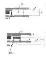
- Fig. 1 an exploded view of an embodiment of the flame ionization detector according to the invention is shown. It comprises three substrates, a middle substrate 1 made of silicon and a lower substrate 2 and an upper substrate 3 made of pyrex glass.
- the middle silicon substrate 1 a part of the combustion chamber 4, the sample gas nozzle 5 and the fuel gas nozzle 6 are worked out by known methods of microsystems technology. Tip-shaped projections 7, which protrude into the combustion chamber 4 in the vicinity of the nozzles 5, 6, can be acted upon by a high-voltage pulse for ignition.
- the lower substrate 2 and the upper substrate 3 are provided in the region of the combustion chamber 4 with trough-shaped recesses, which are provided with a reflective metallization 8.
- the metallization 8 is in this case with bonding islands 9 connected, can take place via the electrical connection.
- the lower substrate 2 in the figures also has a fuel gas inlet 10, while the upper substrate 3 has a sample gas inlet 11. These inlets, after the three substrates are connected by anodic bonding, are in communication with the nozzles 5, 6.
- Fig. 2 is a sectional view along the angled line A-A'-A "of Fig. 1 shown.
- the fuel gas and the sample gas enter through suitable channels in the combustion chamber 4, which is provided with the metallizations 8.
- These metallizations can be used as the electrodes to which a voltage is applied and the current is measured as shown in FIG Fig. 3 is shown schematically.
- a disadvantage is that not only an ion current between the two electrodes 8 is generated by the voltage source U, which is measured at I, but on the one hand, a current due to the limited conductivity of the substrates 1, 2 and 3 and a current passing through precipitated moisture is effected.
- a protective electrode 12 Only one of the metallizations 8, namely the lower one in FIG. 12, is electrically connected. The other metallization has the sole purpose of reflecting heat back into the combustion chamber 4, so that less fuel gas is needed.
- the substrate 1 serves as a second electrode for the measurement.
- the protective electrode 12 is connected to the substrate 1 via the voltage source U. Currents that flow outside the combustion chamber (before the gases reach the combustion chamber), namely because of the conductivity of the substrates and deposited water, although due to the voltage source U, but by the Ammeter I not measured. Rather, only the currents between substrate 1 and lower electrode 8 are measured, that is to say only the currents which actually result from the flame ionization.
- the flame ionization detector according to the invention can be made very small. Typically, it occupies a footprint of 10 x 10 mm.
- the substrates need only have a thickness of a few 100 microns.
- the nozzle openings for the fuel gas and the measurement gas can be reduced to a few 10 to 100 microns 2 , so as to minimize the fuel gas consumption or to optimize the gas mixture.
- the combustion chamber 4 is shown open to the right in the figures, it is normally closed except for a small opening to avoid turbulence due to external air currents and contaminants.
- the back diffusion from the environment can be prevented, for example, by the combustion chamber 4 communicating with the environment only through a narrow gap, for instance between the middle and one or both adjacent cover substrates or through a small gap in the middle substrate.
- the combustion chamber could be completely closed with water in which the combustion product, namely water, condenses on an additional cooling device.
- the production of the flame ionization detector can, as mentioned, be carried out with the customary techniques of microsystem technology and photolithography.
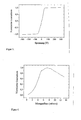
- a typical flame ionization detector of the invention operates at relatively low voltages, as shown in FIG Fig. 6 is shown. Already at a voltage of plus or minus 50 V, saturation occurs. The measurement result is then constant at higher voltage levels. The corresponding curve was recorded with a sample gas flow of 7 ml / min. The dependence of the ion current on the flow rate of the sample gas at a voltage of 100 V is shown in FIG.
Landscapes
- Chemical & Material Sciences (AREA)
- Analytical Chemistry (AREA)
- Physics & Mathematics (AREA)
- Health & Medical Sciences (AREA)
- Life Sciences & Earth Sciences (AREA)
- Biochemistry (AREA)
- General Health & Medical Sciences (AREA)
- General Physics & Mathematics (AREA)
- Immunology (AREA)
- Pathology (AREA)
- Electrochemistry (AREA)
- Chemical Kinetics & Catalysis (AREA)
- Other Investigation Or Analysis Of Materials By Electrical Means (AREA)
Priority Applications (7)
| Application Number | Priority Date | Filing Date | Title |
|---|---|---|---|
| EP07018014A EP2037264A1 (fr) | 2007-09-13 | 2007-09-13 | Détecteur à ionisation de flammes |
| CN200880108178.0A CN101836111B (zh) | 2007-09-13 | 2008-08-18 | 火焰电离检测器 |
| JP2010524370A JP5427178B2 (ja) | 2007-09-13 | 2008-08-18 | 水素炎イオン化検出器 |
| CA2699230A CA2699230C (fr) | 2007-09-13 | 2008-08-18 | Detecteur a ionisation de flamme |
| US12/675,470 US8305086B2 (en) | 2007-09-13 | 2008-08-18 | Flame ionization detector |
| EP08785606A EP2191263B1 (fr) | 2007-09-13 | 2008-08-18 | Détecteur à ionisation de flamme |
| PCT/EP2008/006781 WO2009036854A1 (fr) | 2007-09-13 | 2008-08-18 | Détecteur à ionisation de flamme |
Applications Claiming Priority (1)
| Application Number | Priority Date | Filing Date | Title |
|---|---|---|---|
| EP07018014A EP2037264A1 (fr) | 2007-09-13 | 2007-09-13 | Détecteur à ionisation de flammes |
Publications (1)
| Publication Number | Publication Date |
|---|---|
| EP2037264A1 true EP2037264A1 (fr) | 2009-03-18 |
Family
ID=39090683
Family Applications (2)
| Application Number | Title | Priority Date | Filing Date |
|---|---|---|---|
| EP07018014A Withdrawn EP2037264A1 (fr) | 2007-09-13 | 2007-09-13 | Détecteur à ionisation de flammes |
| EP08785606A Not-in-force EP2191263B1 (fr) | 2007-09-13 | 2008-08-18 | Détecteur à ionisation de flamme |
Family Applications After (1)
| Application Number | Title | Priority Date | Filing Date |
|---|---|---|---|
| EP08785606A Not-in-force EP2191263B1 (fr) | 2007-09-13 | 2008-08-18 | Détecteur à ionisation de flamme |
Country Status (6)
| Country | Link |
|---|---|
| US (1) | US8305086B2 (fr) |
| EP (2) | EP2037264A1 (fr) |
| JP (1) | JP5427178B2 (fr) |
| CN (1) | CN101836111B (fr) |
| CA (1) | CA2699230C (fr) |
| WO (1) | WO2009036854A1 (fr) |
Cited By (4)
| Publication number | Priority date | Publication date | Assignee | Title |
|---|---|---|---|---|
| DE102009035762A1 (de) * | 2009-08-03 | 2011-02-10 | Bayer Technology Services Gmbh | Gegenstrombrenner |
| EP2447716A1 (fr) * | 2010-10-27 | 2012-05-02 | Bayer Technology Services GmbH | Brûleur à contre-courant pour un détecteur à ionisation de flamme |
| EP2693211A1 (fr) * | 2012-08-03 | 2014-02-05 | Krohne Messtechnik GmbH | Procédé de fabrication dýun détecteur d'ionisation de flamme et détecteur d'ionisation de flamme correspondant |
| EP3299807A1 (fr) * | 2016-09-23 | 2018-03-28 | Krohne Messtechnik GmbH | Dispositif de détection de composés organiques |
Families Citing this family (5)
| Publication number | Priority date | Publication date | Assignee | Title |
|---|---|---|---|---|
| US8773137B2 (en) * | 2008-03-07 | 2014-07-08 | Bertelli & Partners, S.R.L. | Method and device to detect the flame in a burner operating on a solid, liquid or gaseous combustible |
| US9389207B2 (en) * | 2012-04-20 | 2016-07-12 | The Board Of Trustees Of The University Of Illinois | Portable gas analyzer |
| DE102013012731A1 (de) | 2013-08-01 | 2015-02-05 | Krohne Messtechnik Gmbh | Verfahren zur Herstellung eines Gaskonverters und entsprechender Gaskonverter |
| DE102014218057B4 (de) * | 2013-09-13 | 2018-04-12 | Waters Technologies Corp. | Mikrofluidischer Flammenionisationsdetektor |
| DE102019126513B4 (de) | 2019-10-01 | 2021-08-26 | Horiba Europe Gmbh | Flammenionisationsdetektor |
Citations (1)
| Publication number | Priority date | Publication date | Assignee | Title |
|---|---|---|---|---|
| US6193501B1 (en) * | 1999-07-06 | 2001-02-27 | The Board Of Trustees Of The University Of Illinois | Microcombustor having submillimeter critical dimensions |
Family Cites Families (12)
| Publication number | Priority date | Publication date | Assignee | Title |
|---|---|---|---|---|
| US5576626A (en) * | 1995-01-17 | 1996-11-19 | Microsensor Technology, Inc. | Compact and low fuel consumption flame ionization detector with flame tip on diffuser |
| DE19755555A1 (de) * | 1997-12-13 | 1999-06-17 | Pierburg Ag | Flammenionisationsdetektor |
| US6701774B2 (en) * | 2000-08-02 | 2004-03-09 | Symyx Technologies, Inc. | Parallel gas chromatograph with microdetector array |
| JP3525384B2 (ja) * | 2001-06-29 | 2004-05-10 | アンデス電気株式会社 | イオン測定器 |
| US7077643B2 (en) * | 2001-11-07 | 2006-07-18 | Battelle Memorial Institute | Microcombustors, microreformers, and methods for combusting and for reforming fluids |
| DE60222304T2 (de) * | 2001-11-20 | 2008-06-05 | Ion Science Ltd., Cambridge | Gasphotoionisationsdetektor |
| US6786716B1 (en) * | 2002-02-19 | 2004-09-07 | Sandia Corporation | Microcombustor |
| DE10310953B4 (de) * | 2003-03-13 | 2006-03-09 | Robert Bosch Gmbh | Unbeheiztes, planares Sensorelement zur Bestimmung der Konzentration einer Gaskomponente in einem Gasgemisch |
| WO2006000099A1 (fr) | 2004-06-25 | 2006-01-05 | Uti Limited Partnership | Detecteur a flamme et procede de chromatographie gazeuse |
| US20060060769A1 (en) * | 2004-09-21 | 2006-03-23 | Predicant Biosciences, Inc. | Electrospray apparatus with an integrated electrode |
| US7273517B1 (en) * | 2005-02-25 | 2007-09-25 | Sandia Corporation | Non-planar microfabricated gas chromatography column |
| CN1945314A (zh) * | 2006-10-20 | 2007-04-11 | 上海精密科学仪器有限公司 | 火焰离子化检测器 |
-
2007
- 2007-09-13 EP EP07018014A patent/EP2037264A1/fr not_active Withdrawn
-
2008
- 2008-08-18 JP JP2010524370A patent/JP5427178B2/ja not_active Expired - Fee Related
- 2008-08-18 US US12/675,470 patent/US8305086B2/en not_active Expired - Fee Related
- 2008-08-18 CA CA2699230A patent/CA2699230C/fr not_active Expired - Fee Related
- 2008-08-18 CN CN200880108178.0A patent/CN101836111B/zh not_active Expired - Fee Related
- 2008-08-18 WO PCT/EP2008/006781 patent/WO2009036854A1/fr active Application Filing
- 2008-08-18 EP EP08785606A patent/EP2191263B1/fr not_active Not-in-force
Patent Citations (1)
| Publication number | Priority date | Publication date | Assignee | Title |
|---|---|---|---|---|
| US6193501B1 (en) * | 1999-07-06 | 2001-02-27 | The Board Of Trustees Of The University Of Illinois | Microcombustor having submillimeter critical dimensions |
Non-Patent Citations (2)
| Title |
|---|
| R. MANGINELL ET AL.: "Micro Flame-Based Detector Suite for Universal Gas Sensing", SANDIA REPORT, no. SAND2005-6236, 2005, SANDIA NATIONAL LABORATORIES,ALBUQUERQUE,NEW MEXICO, US, pages 1 - 36, XP002471362 * |
| ZIMMERMANN S ET AL: "Micro flame ionization detector and micro flame spectrometer", SENSORS AND ACTUATORS B, ELSEVIER SEQUOIA S.A., LAUSANNE, CH, vol. 63, no. 3, May 2000 (2000-05-01), pages 159 - 166, XP004198335, ISSN: 0925-4005 * |
Cited By (9)
| Publication number | Priority date | Publication date | Assignee | Title |
|---|---|---|---|---|
| DE102009035762A1 (de) * | 2009-08-03 | 2011-02-10 | Bayer Technology Services Gmbh | Gegenstrombrenner |
| CN102741613A (zh) * | 2009-08-03 | 2012-10-17 | 拜尔技术服务有限责任公司 | 对流燃烧器 |
| WO2011015285A3 (fr) * | 2009-08-03 | 2012-12-06 | Bayer Technology Services Gmbh | Brûleur à contre-flux |
| CN102741613B (zh) * | 2009-08-03 | 2015-08-12 | 拜耳知识产权有限责任公司 | 对流燃烧器 |
| US9470420B2 (en) | 2009-08-03 | 2016-10-18 | Bayer Intellectual Property Gmbh | Counter-flow combustor |
| EP2447716A1 (fr) * | 2010-10-27 | 2012-05-02 | Bayer Technology Services GmbH | Brûleur à contre-courant pour un détecteur à ionisation de flamme |
| WO2012055835A1 (fr) * | 2010-10-27 | 2012-05-03 | Bayer Technology Services Gmbh | Brûleur à contre-courant pour détecteur à ionisation de flamme |
| EP2693211A1 (fr) * | 2012-08-03 | 2014-02-05 | Krohne Messtechnik GmbH | Procédé de fabrication dýun détecteur d'ionisation de flamme et détecteur d'ionisation de flamme correspondant |
| EP3299807A1 (fr) * | 2016-09-23 | 2018-03-28 | Krohne Messtechnik GmbH | Dispositif de détection de composés organiques |
Also Published As
| Publication number | Publication date |
|---|---|
| CA2699230A1 (fr) | 2009-03-26 |
| JP5427178B2 (ja) | 2014-02-26 |
| JP2010539457A (ja) | 2010-12-16 |
| US20100301870A1 (en) | 2010-12-02 |
| CN101836111B (zh) | 2013-03-20 |
| CA2699230C (fr) | 2016-05-24 |
| US8305086B2 (en) | 2012-11-06 |
| EP2191263A1 (fr) | 2010-06-02 |
| EP2191263B1 (fr) | 2012-06-06 |
| CN101836111A (zh) | 2010-09-15 |
| WO2009036854A1 (fr) | 2009-03-26 |
Similar Documents
| Publication | Publication Date | Title |
|---|---|---|
| EP2191263B1 (fr) | Détecteur à ionisation de flamme | |
| DE68926451T2 (de) | Ionenbeweglichkeitsdetektor | |
| DE2913866C2 (de) | Meßfühler für die Bestimmung von Bestandteilen in strömenden Gasen | |
| EP0020938B1 (fr) | Sonde de mesure polarographique pour déterminer la teneur en oxygène de gaz, notamment de gaz d'échappement de moteurs à combustion interne | |
| DE19513459A1 (de) | Ionenmobilitätsspektrometer mit flexiblen gedruckten Leiterplatten und Verfahren zu dessen Herstellung | |
| DE102009052957A1 (de) | Gassensor mit Prüfgasgenerator | |
| DE3120159C2 (fr) | ||
| EP3299807B1 (fr) | Dispositif de détection de composés organiques | |
| EP2447716A1 (fr) | Brûleur à contre-courant pour un détecteur à ionisation de flamme | |
| DE19924906A1 (de) | Halbleiter-Gassensor, Gassensorsystem und Verfahren zur Gasanalyse | |
| DE102012015204B4 (de) | Verfahren zur Herstellung eines Flammenionisationsdetektors | |
| DE2950105C2 (de) | Atomabsorptionsspektrometer mit verschiedenen, wahlweise einsetzbaren Atomisierungsvorrichtungen | |
| DE3519028C2 (de) | Einrichtung zum Erfassen von klopfenden Verbrennungsvorgängen bei einer Brennkraftmaschine | |
| EP2462381B1 (fr) | Brûleur à contre-flux | |
| DE112016004588T5 (de) | Gassensor | |
| DE3035608A1 (de) | Elektrochemischer messfuehler zur bestimmung des sauerstoffgehaltes in gasen | |
| DE3005928C2 (fr) | ||
| DE102016108545B4 (de) | NDIR-Gassensor und Verfahren zu dessen Kalibrierung | |
| DE102015212086A1 (de) | Sensorelement zur Erfassung mindestens einer Eigenschaft eines Messgases in einem Messgasraum | |
| DE1598914A1 (de) | Flammenionisationskammer | |
| EP1273910B1 (fr) | Elément d'un capteur avec blindage conducteur | |
| DE102019126513B4 (de) | Flammenionisationsdetektor | |
| DE10038095C2 (de) | Anordnung zur Flammenüberwachung von Poren- und Gestrickbrennern | |
| DE102004042483B4 (de) | Vorrichtung und Verfahren zur Bestimmung des Sauerstoffpartialdrucks in Brennstofftanks, insbesondere von Luft- und Raumfahrzeugen, sowie Verwendung der Vorrichtung | |
| DE10051833A1 (de) | Planares Gassensorelement |
Legal Events
| Date | Code | Title | Description |
|---|---|---|---|
| PUAI | Public reference made under article 153(3) epc to a published international application that has entered the european phase |
Free format text: ORIGINAL CODE: 0009012 |
|
| AK | Designated contracting states |
Kind code of ref document: A1 Designated state(s): AT BE BG CH CY CZ DE DK EE ES FI FR GB GR HU IE IS IT LI LT LU LV MC MT NL PL PT RO SE SI SK TR |
|
| AX | Request for extension of the european patent |
Extension state: AL BA HR MK RS |
|
| RAP1 | Party data changed (applicant data changed or rights of an application transferred) |
Owner name: BAYER TECHNOLOGY SERVICES GMBH |
|
| 17P | Request for examination filed |
Effective date: 20090918 |
|
| 17Q | First examination report despatched |
Effective date: 20091013 |
|
| AKX | Designation fees paid |
Designated state(s): AT BE BG CH CY CZ DE DK EE ES FI FR GB GR HU IE IS IT LI LT LU LV MC MT NL PL PT RO SE SI SK TR |
|
| GRAP | Despatch of communication of intention to grant a patent |
Free format text: ORIGINAL CODE: EPIDOSNIGR1 |
|
| GRAS | Grant fee paid |
Free format text: ORIGINAL CODE: EPIDOSNIGR3 |
|
| STAA | Information on the status of an ep patent application or granted ep patent |
Free format text: STATUS: THE APPLICATION IS DEEMED TO BE WITHDRAWN |
|
| 18D | Application deemed to be withdrawn |
Effective date: 20100915 |