EP2037264A1 - Flame ionisation detector - Google Patents
Flame ionisation detector Download PDFInfo
- Publication number
- EP2037264A1 EP2037264A1 EP07018014A EP07018014A EP2037264A1 EP 2037264 A1 EP2037264 A1 EP 2037264A1 EP 07018014 A EP07018014 A EP 07018014A EP 07018014 A EP07018014 A EP 07018014A EP 2037264 A1 EP2037264 A1 EP 2037264A1
- Authority
- EP
- European Patent Office
- Prior art keywords
- flame ionization
- ionization detector
- detector according
- substrates
- substrate
- Prior art date
- Legal status (The legal status is an assumption and is not a legal conclusion. Google has not performed a legal analysis and makes no representation as to the accuracy of the status listed.)
- Withdrawn
Links
- 239000000758 substrate Substances 0.000 claims abstract description 72
- 239000007789 gas Substances 0.000 claims abstract description 31
- 238000002485 combustion reaction Methods 0.000 claims abstract description 28
- 239000011521 glass Substances 0.000 claims abstract description 7
- 229910052710 silicon Inorganic materials 0.000 claims abstract description 6
- 239000010703 silicon Substances 0.000 claims abstract description 6
- 239000005388 borosilicate glass Substances 0.000 claims abstract description 3
- 239000002737 fuel gas Substances 0.000 claims description 11
- 238000005516 engineering process Methods 0.000 claims description 9
- 230000001681 protective effect Effects 0.000 claims description 5
- 230000006698 induction Effects 0.000 claims description 2
- 238000005259 measurement Methods 0.000 abstract description 6
- 238000004519 manufacturing process Methods 0.000 abstract description 3
- 239000000567 combustion gas Substances 0.000 abstract 1
- 238000001465 metallisation Methods 0.000 description 6
- 238000000034 method Methods 0.000 description 6
- XLYOFNOQVPJJNP-UHFFFAOYSA-N water Substances O XLYOFNOQVPJJNP-UHFFFAOYSA-N 0.000 description 6
- XUIMIQQOPSSXEZ-UHFFFAOYSA-N Silicon Chemical compound [Si] XUIMIQQOPSSXEZ-UHFFFAOYSA-N 0.000 description 4
- 238000001816 cooling Methods 0.000 description 2
- 238000004880 explosion Methods 0.000 description 2
- 239000000203 mixture Substances 0.000 description 2
- 239000000126 substance Substances 0.000 description 2
- RZVAJINKPMORJF-UHFFFAOYSA-N Acetaminophen Chemical compound CC(=O)NC1=CC=C(O)C=C1 RZVAJINKPMORJF-UHFFFAOYSA-N 0.000 description 1
- UFHFLCQGNIYNRP-UHFFFAOYSA-N Hydrogen Chemical compound [H][H] UFHFLCQGNIYNRP-UHFFFAOYSA-N 0.000 description 1
- QVGXLLKOCUKJST-UHFFFAOYSA-N atomic oxygen Chemical compound [O] QVGXLLKOCUKJST-UHFFFAOYSA-N 0.000 description 1
- 230000009286 beneficial effect Effects 0.000 description 1
- 125000004432 carbon atom Chemical group C* 0.000 description 1
- 238000000451 chemical ionisation Methods 0.000 description 1
- 238000006243 chemical reaction Methods 0.000 description 1
- 238000004891 communication Methods 0.000 description 1
- 150000001875 compounds Chemical class 0.000 description 1
- 238000010276 construction Methods 0.000 description 1
- 239000000356 contaminant Substances 0.000 description 1
- 239000013078 crystal Substances 0.000 description 1
- 238000009792 diffusion process Methods 0.000 description 1
- 238000005868 electrolysis reaction Methods 0.000 description 1
- 239000002360 explosive Substances 0.000 description 1
- 238000004817 gas chromatography Methods 0.000 description 1
- 239000001257 hydrogen Substances 0.000 description 1
- 229910052739 hydrogen Inorganic materials 0.000 description 1
- 239000012535 impurity Substances 0.000 description 1
- 150000002894 organic compounds Chemical class 0.000 description 1
- 239000001301 oxygen Substances 0.000 description 1
- 229910052760 oxygen Inorganic materials 0.000 description 1
- 238000001259 photo etching Methods 0.000 description 1
- 238000000206 photolithography Methods 0.000 description 1
- 239000005297 pyrex Substances 0.000 description 1
- 239000012855 volatile organic compound Substances 0.000 description 1
Images

Classifications
-
- G—PHYSICS
- G01—MEASURING; TESTING
- G01N—INVESTIGATING OR ANALYSING MATERIALS BY DETERMINING THEIR CHEMICAL OR PHYSICAL PROPERTIES
- G01N30/00—Investigating or analysing materials by separation into components using adsorption, absorption or similar phenomena or using ion-exchange, e.g. chromatography or field flow fractionation
- G01N30/02—Column chromatography
- G01N30/62—Detectors specially adapted therefor
- G01N30/64—Electrical detectors
- G01N30/68—Flame ionisation detectors
-
- G—PHYSICS
- G01—MEASURING; TESTING
- G01N—INVESTIGATING OR ANALYSING MATERIALS BY DETERMINING THEIR CHEMICAL OR PHYSICAL PROPERTIES
- G01N27/00—Investigating or analysing materials by the use of electric, electrochemical, or magnetic means
- G01N27/62—Investigating or analysing materials by the use of electric, electrochemical, or magnetic means by investigating the ionisation of gases, e.g. aerosols; by investigating electric discharges, e.g. emission of cathode
- G01N27/626—Investigating or analysing materials by the use of electric, electrochemical, or magnetic means by investigating the ionisation of gases, e.g. aerosols; by investigating electric discharges, e.g. emission of cathode using heat to ionise a gas
-
- G—PHYSICS
- G01—MEASURING; TESTING
- G01N—INVESTIGATING OR ANALYSING MATERIALS BY DETERMINING THEIR CHEMICAL OR PHYSICAL PROPERTIES
- G01N30/00—Investigating or analysing materials by separation into components using adsorption, absorption or similar phenomena or using ion-exchange, e.g. chromatography or field flow fractionation
- G01N30/02—Column chromatography
- G01N30/60—Construction of the column
- G01N30/6095—Micromachined or nanomachined, e.g. micro- or nanosize
Definitions
- the invention relates to a flame ionization detector (FID) comprising a fuel gas supply and igniter, a sample gas supply, a combustion chamber in which the sample gas is ionized by the flame, and electrodes to generate and measure the ionic current a voltage is applied.
- FID flame ionization detector
- Flame ionization detectors serve to detect and measure volatile organic compounds in gaseous samples. The measurement is based on the chemical ionization of organic substances, which are pyrolyzed in a blast gas flame. An ionization reaction of the carbon atoms contained in the substance takes place: CH + O ⁇ CHO + + e -
- a voltage is applied to a pair of electrodes arranged at the edge of the flame, an ion current flows which can be measured and used to detect the organic compounds. If the gas first passes through a gas chromatograph, for example a capillary gas chromatograph, then the various chemical compounds of the sample gas, sorted by molecular weight, enter the flame ionization detector one after the other, so that the concentration the various components can be determined.
- a gas chromatograph for example a capillary gas chromatograph
- oxyhydrogen gas must be supplied to a high explosive mixture of oxygen and hydrogen. It is therefore desirable to make the flame ionization detectors as small as possible so that only small amounts of oxyhydrogen are needed and the risk of explosion is thereby reduced. In addition, such small flame ionization detectors are of course beneficial because they are easier to transport and require less space. Further, because of the lower consumption of oxyhydrogen gas, it is not possible to use it in stored form but to produce it locally by electrolysis, further reducing the risk of explosion.
- Such a flame ionization detector making use of this advantage consists of components manufactured according to the methods of microsystem technology ( Zimmermann et al., Micro flame ionization detector and microflame spectrometer, Sensors and Actuators B63 (2000), pp. 159-166 ; Zimmermann et al., Miniaturized Flame Ionization Detector for Gas Chromatography, Sensors and Actuators B83 (2002), pp. 285-289 ).
- the oxyhydrogen flame burns in the open space and is surrounded only by a metallized glass tube, which forms an electrode pair together with the silicon substrate. As the flame burns in open space, the result can be affected by turbulence and impurities.
- the object of the invention is to provide a flame ionization detector which is small in size and can be manufactured entirely by the methods of microsystem technology.
- the flame ionization detector is characterized in that it is constructed as an integrated planar system of at least three parallel interconnected platelet-shaped substrates, which are processed by microsystem technology, wherein a central substrate nozzles for the gases and the ignition device and a recess having a Part of the combustion chamber is formed, which is completed by recesses in the adjacent substrates and is closed by these substrates substantially together with the nozzle region, and the adjacent substrates have feed channels for the gases.
- the flame ionization detector according to the invention thus essentially consists of three platelet-shaped substrates, although further substrates could be provided. These substrates are produced exclusively by the means of microsystem technology by photoetching and the like.
- the middle substrate has nozzles for the gases and the igniter and a recess forming part of the combustion chamber.
- the combustion chamber is completed by recesses in the adjacent substrates. While the central substrate may be completely broken in the region of the combustion chamber, the adjacent substrates have troughs, which close the combustion chamber after assembly, so that the combustion chamber is substantially closed.
- “Essentially closed” means that the combustion chamber must have only a small opening through which the gases can escape to the outside. One might even consider closing the combustion chamber completely by providing a cooling device to which the exclusive combustion product, namely water, condenses. One would then only have to take appropriate measures that the water is removed.
- the two adjacent or outer substrates not only surround the combustion chamber, but also the nozzle area. While the nozzles for the fuel gas and the sample gas are provided in the central substrate, the supply of these gases takes place by supply channels in the adjacent or outer substrates.
- the middle substrate is conductive and the adjacent substrates are substantially non-conductive.
- Essentially non-conductive means that the conductivity is low even at elevated temperatures, but nevertheless so high that anodic bonding of the substrates is possible, which presupposes a certain conductivity of the components. However, this conductivity should not be too high, since not only ion currents that are to be measured, but also leakage currents take place through the substrate, which can falsify the measurement result.
- one electrode is arranged in each case in the region of the combustion chamber in the adjacent substrates. So there are electrodes on both sides of the combustion chamber.
- the disadvantage is that when a voltage is applied to the two electrodes, not only the ion current is measured, but also the current that flows from one electrode to another due to the non-zero conductivity of the outer substrates and water, that has settled.
- a protective electrode according to the invention through which these currents are absorbed.
- an electrode is formed by the middle substrate and, on the other hand, the protective electrode is located next to the second electrode on one of the two adjacent substrates, between the two electrodes. Currents flowing from one adjacent substrate to the other adjacent substrate are in this case picked up by the guard electrode and not measured.
- the flame ionization detector Due to the high temperature of the flame (up to 2700 ° C) the flame ionization detector is strongly heated. To stress cracks To avoid all parts have expediently rounded outlines.
- the nozzles for the gases are formed as a buried structure and covered by at least one further substrate. In this way one can achieve symmetrical arrangement of the nozzles.
- the middle substrate has an electrode tip immediately behind the nozzles. About this electrode tip and an electrode on one of the two adjacent substrates, a high voltage pulse for igniting the flame can be applied. Such a high voltage pulse could be generated for example by a piezo crystal.
- the flame ionization detector can also be used to generate electrical energy by providing it with two high induction magnets, thereby forming a magnetohydrodynamic generator.
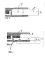
- Fig. 1 an exploded view of an embodiment of the flame ionization detector according to the invention is shown. It comprises three substrates, a middle substrate 1 made of silicon and a lower substrate 2 and an upper substrate 3 made of pyrex glass.
- the middle silicon substrate 1 a part of the combustion chamber 4, the sample gas nozzle 5 and the fuel gas nozzle 6 are worked out by known methods of microsystems technology. Tip-shaped projections 7, which protrude into the combustion chamber 4 in the vicinity of the nozzles 5, 6, can be acted upon by a high-voltage pulse for ignition.
- the lower substrate 2 and the upper substrate 3 are provided in the region of the combustion chamber 4 with trough-shaped recesses, which are provided with a reflective metallization 8.
- the metallization 8 is in this case with bonding islands 9 connected, can take place via the electrical connection.
- the lower substrate 2 in the figures also has a fuel gas inlet 10, while the upper substrate 3 has a sample gas inlet 11. These inlets, after the three substrates are connected by anodic bonding, are in communication with the nozzles 5, 6.
- Fig. 2 is a sectional view along the angled line A-A'-A "of Fig. 1 shown.
- the fuel gas and the sample gas enter through suitable channels in the combustion chamber 4, which is provided with the metallizations 8.
- These metallizations can be used as the electrodes to which a voltage is applied and the current is measured as shown in FIG Fig. 3 is shown schematically.
- a disadvantage is that not only an ion current between the two electrodes 8 is generated by the voltage source U, which is measured at I, but on the one hand, a current due to the limited conductivity of the substrates 1, 2 and 3 and a current passing through precipitated moisture is effected.
- a protective electrode 12 Only one of the metallizations 8, namely the lower one in FIG. 12, is electrically connected. The other metallization has the sole purpose of reflecting heat back into the combustion chamber 4, so that less fuel gas is needed.
- the substrate 1 serves as a second electrode for the measurement.
- the protective electrode 12 is connected to the substrate 1 via the voltage source U. Currents that flow outside the combustion chamber (before the gases reach the combustion chamber), namely because of the conductivity of the substrates and deposited water, although due to the voltage source U, but by the Ammeter I not measured. Rather, only the currents between substrate 1 and lower electrode 8 are measured, that is to say only the currents which actually result from the flame ionization.
- the flame ionization detector according to the invention can be made very small. Typically, it occupies a footprint of 10 x 10 mm.
- the substrates need only have a thickness of a few 100 microns.
- the nozzle openings for the fuel gas and the measurement gas can be reduced to a few 10 to 100 microns 2 , so as to minimize the fuel gas consumption or to optimize the gas mixture.
- the combustion chamber 4 is shown open to the right in the figures, it is normally closed except for a small opening to avoid turbulence due to external air currents and contaminants.
- the back diffusion from the environment can be prevented, for example, by the combustion chamber 4 communicating with the environment only through a narrow gap, for instance between the middle and one or both adjacent cover substrates or through a small gap in the middle substrate.
- the combustion chamber could be completely closed with water in which the combustion product, namely water, condenses on an additional cooling device.
- the production of the flame ionization detector can, as mentioned, be carried out with the customary techniques of microsystem technology and photolithography.
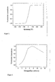
- a typical flame ionization detector of the invention operates at relatively low voltages, as shown in FIG Fig. 6 is shown. Already at a voltage of plus or minus 50 V, saturation occurs. The measurement result is then constant at higher voltage levels. The corresponding curve was recorded with a sample gas flow of 7 ml / min. The dependence of the ion current on the flow rate of the sample gas at a voltage of 100 V is shown in FIG.
Abstract
Description
Die Erfindung betrifft einen Flammenionisationsdetektor (FID), der eine Zuführung und eine Zündeinrichtung für das Brenngas, eine Zuführung für das Probengas, eine Brennkammer, in der das Probengas durch die Flamme ionisiert wird, und Elektroden aufweist, an die zur Erzeugung und Messung des Ionenstroms eine Spannung angelegt wird.The invention relates to a flame ionization detector (FID) comprising a fuel gas supply and igniter, a sample gas supply, a combustion chamber in which the sample gas is ionized by the flame, and electrodes to generate and measure the ionic current a voltage is applied.
Flammenionisationsdetektoren dienen dazu, flüchtige organische Verbindungen in gasförmigen Proben festzustellen und zu messen. Die Messung beruht auf der chemischen Ionisation von organischen Substanzen, die in einer Knallgasflamme pyrolysiert werden. Es findet dabei eine Ionisationsreaktion der in der Substanz enthaltenen Kohlenstoffatome statt:
CH + O → CHO+ + e-
Flame ionization detectors serve to detect and measure volatile organic compounds in gaseous samples. The measurement is based on the chemical ionization of organic substances, which are pyrolyzed in a blast gas flame. An ionization reaction of the carbon atoms contained in the substance takes place:
CH + O → CHO + + e -
Legt man an ein am Rand der Flamme angeordnetes Elektrodenpaar eine Spannung an, so fließt ein Ionenstrom, der gemessen werden kann und zum Nachweis der organischen Verbindungen dienen kann. Durchläuft das Gas zunächst einen Gaschromatographen, zum Beispiel einen Kapillargaschromatographen, so treten die verschiedenen chemischen Verbindungen des Probengases, sortiert nach Molekulargewicht, nacheinander in den Flammenionisationsdetektor ein, so dass die Konzentration der verschiedenen Komponenten festgestellt werden kann.If a voltage is applied to a pair of electrodes arranged at the edge of the flame, an ion current flows which can be measured and used to detect the organic compounds. If the gas first passes through a gas chromatograph, for example a capillary gas chromatograph, then the various chemical compounds of the sample gas, sorted by molecular weight, enter the flame ionization detector one after the other, so that the concentration the various components can be determined.
Ein Problem bei Flammenionisationsdetektoren besteht darin, dass Knallgas, eine hochexplosive Mischung von Sauerstoff und Wasserstoff zugeführt werden muss. Man ist daher bestrebt, die Flammenionisationsdetektoren möglichst klein zu machen, damit man nur geringe Mengen von Knallgas benötigt und die Explosionsgefahr dadurch vermindert wird. Außerdem sind solche kleinen Flammenionisationsdetektoren natürlich von Vorteil, da sie leichter transportierbar sind und weniger Platz benötigen. Weiter ist es wegen des geringeren Verbrauchs an Knallgas möglich, dieses nicht in gespeicherter Form zu verwenden, sondern vor Ort durch Elektrolyse herzustellen, was die Explosionsgefahr weiter verringert. Ein solcher Flammenionisationsdetektor, der von diesem Vorteil Gebrauch macht, besteht aus Komponenten, die nach den Verfahren der Mikrosystemtechnik hergestellt sind (
Auch weitere vorbekannte Flammenionisationsdetektoren kleiner Bauart weisen den Nachteil auf, dass sie nicht oder nicht vollständig mit den Verfahren der Mikrosystemtechnik hergestellt werden können (
Die Aufgabe der Erfindung besteht in der Schaffung eines Flammenionisationsdetektors, der geringe Größe hat und vollständig mit den Verfahren der Mikrosystemtechnik hergestellt werden kann.The object of the invention is to provide a flame ionization detector which is small in size and can be manufactured entirely by the methods of microsystem technology.
Erfindungsgemäß ist der Flammenionisationsdetektor dadurch gekennzeichnet, dass er als integriertes planares System aus mindestens drei parallelen miteinander verbundenen plättchenförmigen Substraten aufgebaut ist, die mit Verfahren der Mikrosystemtechnik bearbeitet sind, wobei ein mittleres Substrat Düsen für die Gase und die Zündeinrichtung und eine Ausnehmung aufweist, die einen Teil der Brennkammer bildet, die durch Ausnehmungen in den benachbarten Substraten vervollständigt wird und durch diese Substrate im Wesentlichen zusammen mit dem Düsenbereich verschlossen ist, und die benachbarten Substrate Zuführkanäle für die Gase aufweisen.According to the invention, the flame ionization detector is characterized in that it is constructed as an integrated planar system of at least three parallel interconnected platelet-shaped substrates, which are processed by microsystem technology, wherein a central substrate nozzles for the gases and the ignition device and a recess having a Part of the combustion chamber is formed, which is completed by recesses in the adjacent substrates and is closed by these substrates substantially together with the nozzle region, and the adjacent substrates have feed channels for the gases.
Der erfindungsgemäße Flammenionisationsdetektor besteht also im Wesentlichen aus drei plättchenförmigen Substraten, wobei allerdings weitere Substrate vorgesehen sein könnten. Diese Substrate sind ausschließlich mit den Mitteln der Mikrosystemtechnik durch Fotoätzen und dergleichen hergestellt. Das mittlere Substrat weist dabei Düsen für die Gase und die Zündeinrichtung und eine Ausnehmung auf, die einen Teil der Brennkammer bildet. Die Brennkammer wird durch Ausnehmungen in den benachbarten Substraten vervollständigt. Während das mittlere Substrat im Bereich der Brennkammer vollständig durchbrochen sein kann, weisen die benachbarten Substrate Mulden auf, die nach dem Zusammenbau die Brennkammer abschließen, so dass die Brennkammer im Wesentlichen geschlossen ist. "Im Wesentlichen geschlossen" bedeutet dabei, dass die Brennkammer nur eine kleine Öffnung aufweisen muss, durch die die Gase nach außen entweichen können. Man könnte sogar daran denken, die Brennkammer vollständig zu schließen, wenn man eine Kühleinrichtung vorsieht, an der das ausschließliche Verbrennungsprodukt, nämlich Wasser, kondensiert. Man müsste dann nur für geeignete Maßnahmen sorgen, dass das Wasser abgeführt wird.The flame ionization detector according to the invention thus essentially consists of three platelet-shaped substrates, although further substrates could be provided. These substrates are produced exclusively by the means of microsystem technology by photoetching and the like. The middle substrate has nozzles for the gases and the igniter and a recess forming part of the combustion chamber. The combustion chamber is completed by recesses in the adjacent substrates. While the central substrate may be completely broken in the region of the combustion chamber, the adjacent substrates have troughs, which close the combustion chamber after assembly, so that the combustion chamber is substantially closed. "Essentially closed" means that the combustion chamber must have only a small opening through which the gases can escape to the outside. One might even consider closing the combustion chamber completely by providing a cooling device to which the exclusive combustion product, namely water, condenses. One would then only have to take appropriate measures that the water is removed.
Die beiden benachbarten oder äußeren Substrate umschließen aber nicht nur die Brennkammer, sondern auch den Düsenbereich. Während die Düsen für das Brenngas und das Probengas im mittleren Substrat vorgesehen sind, erfolgt die Zuleitung dieser Gase durch Zuführkanäle in den benachbarten oder äußeren Substraten.However, the two adjacent or outer substrates not only surround the combustion chamber, but also the nozzle area. While the nozzles for the fuel gas and the sample gas are provided in the central substrate, the supply of these gases takes place by supply channels in the adjacent or outer substrates.
Bei einer vorteilhaften Ausführungsform ist das mittlere Substrat leitfähig und die benachbarten Substrate im Wesentlichen nicht leitend. "Im Wesentlichen nicht leitend" bedeutet dabei, dass die Leitfähigkeit auch bei erhöhter Temperatur gering ist, aber doch so groß, dass anodisches Bonden der Substrate möglich ist, was ja eine gewisse Leitfähigkeit der Komponenten voraussetzt. Diese Leitfähigkeit sollte aber nicht zu hoch sein, da dadurch nicht nur Ionenströme, die gemessen werden sollen, sondern auch Leckströme durch das Substrat stattfinden, die das Messergebnis verfälschen können.In an advantageous embodiment, the middle substrate is conductive and the adjacent substrates are substantially non-conductive. "Essentially non-conductive" means that the conductivity is low even at elevated temperatures, but nevertheless so high that anodic bonding of the substrates is possible, which presupposes a certain conductivity of the components. However, this conductivity should not be too high, since not only ion currents that are to be measured, but also leakage currents take place through the substrate, which can falsify the measurement result.
Vorteilhafterweise bestehen das mittlere Substrat aus Silizium und die benachbarten Substrate aus Glas, wobei als Glas insbesondere Borosilikatglas sich als besonders vorteilhaft erwiesen hat.Advantageously, the middle substrate of silicon and the adjacent substrates made of glass, wherein as glass in particular borosilicate glass has been found to be particularly advantageous.
Bei einer vorteilhaften Ausführungsform ist je eine Elektrode im Bereich der Brennkammer in den benachbarten Substraten angeordnet. Es befinden sich also Elektroden auf beiden Seiten der Brennkammer. Der Nachteil besteht dabei, dass dann, wenn eine Spannung an die beiden Elektroden angelegt wird, nicht nur der Ionenstrom gemessen wird, sondern auch der Strom, der von einer Elektrode zur anderen aufgrund der von Null verschiedenen Leitfähigkeit der äußeren Substrate und von Wasser fließt, das sich abgesetzt hat.In an advantageous embodiment, one electrode is arranged in each case in the region of the combustion chamber in the adjacent substrates. So there are electrodes on both sides of the combustion chamber. The disadvantage is that when a voltage is applied to the two electrodes, not only the ion current is measured, but also the current that flows from one electrode to another due to the non-zero conductivity of the outer substrates and water, that has settled.
Dieser Nachteil kann durch eine erfindungsgemäße Schutzelektrode vermieden werden, durch die diese Ströme aufgenommen werden. Bei einer vorteilhaften Ausführungsform wird dabei zum einen eine Elektrode durch das mittlere Substrat gebildet und zum anderen befindet die Schutzelektrode sich neben der zweiten Elektrode auf einem der beiden benachbarten Substrate, zwischen den beiden Elektroden. Ströme, die vom einen benachbarten Substrat zum anderen benachbarten Substrat fließen, werden in diesem Fall von der Schutzelektrode aufgenommen und nicht mitgemessen.This disadvantage can be avoided by a protective electrode according to the invention, through which these currents are absorbed. In an advantageous embodiment, on the one hand, an electrode is formed by the middle substrate and, on the other hand, the protective electrode is located next to the second electrode on one of the two adjacent substrates, between the two electrodes. Currents flowing from one adjacent substrate to the other adjacent substrate are in this case picked up by the guard electrode and not measured.
Aufgrund der hohen Temperatur der Flamme (bis 2700°C) wird der Flammenionisationsdetektor stark erwärmt. Um Spannungsrisse zu vermeiden, haben zweckmäßigerweise alle Teile abgerundete Konturen.Due to the high temperature of the flame (up to 2700 ° C) the flame ionization detector is strongly heated. To stress cracks To avoid all parts have expediently rounded outlines.
Wenn die Elektroden an den benachbarten Substraten verspiegelt sind, wird Wärme von der Flamme in die Brennkammer zurückreflektiert. Es wird einerseits weniger Brenngas benötigt. Andererseits wird der Detektor weniger erwärmt.When the electrodes on the adjacent substrates are mirrored, heat from the flame is reflected back into the combustion chamber. On the one hand less fuel gas is needed. On the other hand, the detector is heated less.
Bei einer vorteilhaften Ausführungsform sind die Düsen für die Gase als vergrabene Struktur ausgebildet und durch mindestens ein weiteres Substrat abgedeckt. Auf diese Weise kann man symmetrische Anordnung der Düsen erreichen.In an advantageous embodiment, the nozzles for the gases are formed as a buried structure and covered by at least one further substrate. In this way one can achieve symmetrical arrangement of the nozzles.
Vorteilhafterweise weist das mittlere Substrat eine Elektrodenspitze unmittelbar hinter den Düsen auf. Über diese Elektrodenspitze und eine Elektrode auf einer der beiden benachbarten Substrate ist ein Hochspannungspuls zum Zünden der Flamme anlegbar. Ein solcher Hochspannungsimpuls könnte zum Beispiel durch einen Piezo-Kristall erzeugt werden. Der Flammenionisationsdetektor kann auch zur Erzeugung elektrischer Energie verwendet werden, indem er mit zwei Magneten hoher Induktion versehen ist und dadurch einen magnetohydrodynamischen Generator bildet.Advantageously, the middle substrate has an electrode tip immediately behind the nozzles. About this electrode tip and an electrode on one of the two adjacent substrates, a high voltage pulse for igniting the flame can be applied. Such a high voltage pulse could be generated for example by a piezo crystal. The flame ionization detector can also be used to generate electrical energy by providing it with two high induction magnets, thereby forming a magnetohydrodynamic generator.
Die Erfindung wird im Folgenden anhand von vorteilhaften Ausführungsformen unter Bezugnahme auf die beigefügten Zeichnungen beschrieben. Es zeigen:
- Fig. 1
- in Explosionsansicht eine Ausführungsform des erfindungsgemäßen Flammenionisations- detektors;
- Fig. 2
- eine Schnittansicht entlang der gewinkel- ten Linie A-A'-A" von
Fig. 1 ; - Fig. 3
- im Schnitt in entsprechender Darstellung wie
Fig. 2 eine Messanordnung; - Fig. 4
- im Schnitt in entsprechender Darstellung wie
Fig. 2 eine zweite besonders vorteil- hafte Ausführungsform der Messanordnung; - Fig. 5
- die Abhängigkeit des Ionenstroms von der angelegten Spannung bei einer vorteilhaf- ten Ausführungsform; und
- Fig. 6
- die Abhängigkeit des Ionenstroms von der Strömungsgeschwindigkeit des Probengases.
- Fig. 1
- an exploded view of an embodiment of the flame ionization detector according to the invention;
- Fig. 2
- a sectional view along the angled line A-A'-A "of
Fig. 1 ; - Fig. 3
- on average in the corresponding representation as
Fig. 2 a measuring arrangement; - Fig. 4
- on average in the corresponding representation as
Fig. 2 a second particularly advantageous embodiment of the measuring arrangement; - Fig. 5
- the dependence of the ion current on the applied voltage in an advantageous embodiment; and
- Fig. 6
- the dependence of the ion current on the flow rate of the sample gas.
In
Das untere Substrat 2 und das obere Substrat 3 sind im Bereich der Brennkammer 4 mit muldenförmigen Ausnehmungen versehen, die mit einer spiegelnden Metallisierung 8 versehen sind. Die Metallisierung 8 ist dabei mit Bondinseln 9 verbunden, über die elektrischer Anschluss stattfinden kann. Das in den Figuren untere Substrat 2 weist noch einen Brenngaseinlass 10 auf, während das obere Substrat 3 einen Probengaseinlass 11 aufweist. Diese Einlässe sind, nachdem die drei Substrate durch anodisches Bonden verbunden sind, in Verbindung mit den Düsen 5, 6.The
In
Dieser Nachteil wird bei der Ausführungsform der
Der erfindungsgemäße Flammenionisationsdetektor kann sehr klein gemacht werden. Typischerweise nimmt er eine Grundfläche von 10 x 10 mm ein. Die Substrate brauchen nur eine Dicke von wenigen 100 µm aufzuweisen. Die Düsenöffnungen für das Brenngas und das Messgas können auf wenige 10 bis 100 µm2 verringert werden, um damit den Brenngasverbrauch zu minimieren beziehungsweise die Gasvermischung zu optimieren. Obwohl in den Figuren die Brennkammer 4 nach rechts hin offen gezeigt ist, wird sie normalerweise bis auf eine kleine Öffnung verschlossen, um Turbulenzen aufgrund äußerer Luftströmungen und Verunreinigungen zu vermeiden. Die Rückdiffusion aus der Umgebung kann zum Beispiel dadurch verhindert werden, dass der Brennraum 4 nur durch einen schmalen Spalt mit der Umgebung in Verbindung steht, etwa zwischen dem mittleren und einem oder beiden benachbarten Decksubstrate oder durch einen kleinen Spalt im mittleren Substrat. Die Brennkammer könnte vollständig mit Wasser verschlossen werden in dem das Verbrennungsprodukt, nämlich Wasser, an einer zusätzlichen Kühleinrichtung kondensiert.The flame ionization detector according to the invention can be made very small. Typically, it occupies a footprint of 10 x 10 mm. The substrates need only have a thickness of a few 100 microns. The nozzle openings for the fuel gas and the measurement gas can be reduced to a few 10 to 100 microns 2 , so as to minimize the fuel gas consumption or to optimize the gas mixture. Although the
Die Herstellung des Flammenionisationsdetektors kann wie erwähnt mit den üblichen Techniken der Mikrosystemtechnik und Fotolithographie erfolgen.The production of the flame ionization detector can, as mentioned, be carried out with the customary techniques of microsystem technology and photolithography.
Ein typischer erfindungsgemäßer Flammenionisationsdetektor arbeitet mit verhältnismäßig niedrigen Spannungen, wie dies in
Claims (12)
Priority Applications (7)
| Application Number | Priority Date | Filing Date | Title |
|---|---|---|---|
| EP07018014A EP2037264A1 (en) | 2007-09-13 | 2007-09-13 | Flame ionisation detector |
| CN200880108178.0A CN101836111B (en) | 2007-09-13 | 2008-08-18 | Flame ionization detector |
| JP2010524370A JP5427178B2 (en) | 2007-09-13 | 2008-08-18 | Hydrogen flame ionization detector |
| EP08785606A EP2191263B1 (en) | 2007-09-13 | 2008-08-18 | Flame ionization detector |
| US12/675,470 US8305086B2 (en) | 2007-09-13 | 2008-08-18 | Flame ionization detector |
| CA2699230A CA2699230C (en) | 2007-09-13 | 2008-08-18 | Flame ionization detector |
| PCT/EP2008/006781 WO2009036854A1 (en) | 2007-09-13 | 2008-08-18 | Flame ionization detector |
Applications Claiming Priority (1)
| Application Number | Priority Date | Filing Date | Title |
|---|---|---|---|
| EP07018014A EP2037264A1 (en) | 2007-09-13 | 2007-09-13 | Flame ionisation detector |
Publications (1)
| Publication Number | Publication Date |
|---|---|
| EP2037264A1 true EP2037264A1 (en) | 2009-03-18 |
Family
ID=39090683
Family Applications (2)
| Application Number | Title | Priority Date | Filing Date |
|---|---|---|---|
| EP07018014A Withdrawn EP2037264A1 (en) | 2007-09-13 | 2007-09-13 | Flame ionisation detector |
| EP08785606A Not-in-force EP2191263B1 (en) | 2007-09-13 | 2008-08-18 | Flame ionization detector |
Family Applications After (1)
| Application Number | Title | Priority Date | Filing Date |
|---|---|---|---|
| EP08785606A Not-in-force EP2191263B1 (en) | 2007-09-13 | 2008-08-18 | Flame ionization detector |
Country Status (6)
| Country | Link |
|---|---|
| US (1) | US8305086B2 (en) |
| EP (2) | EP2037264A1 (en) |
| JP (1) | JP5427178B2 (en) |
| CN (1) | CN101836111B (en) |
| CA (1) | CA2699230C (en) |
| WO (1) | WO2009036854A1 (en) |
Cited By (4)
| Publication number | Priority date | Publication date | Assignee | Title |
|---|---|---|---|---|
| DE102009035762A1 (en) * | 2009-08-03 | 2011-02-10 | Bayer Technology Services Gmbh | Counterflow burner |
| EP2447716A1 (en) * | 2010-10-27 | 2012-05-02 | Bayer Technology Services GmbH | Counterflow burner for a flame ionisation detector |
| EP2693211A1 (en) * | 2012-08-03 | 2014-02-05 | Krohne Messtechnik GmbH | Method for producing a flame ionisation detector and corresponding flame ionisation detector |
| EP3299807A1 (en) * | 2016-09-23 | 2018-03-28 | Krohne Messtechnik GmbH | Device for detecting organic compounds |
Families Citing this family (5)
| Publication number | Priority date | Publication date | Assignee | Title |
|---|---|---|---|---|
| EP2265867B1 (en) * | 2008-03-07 | 2018-11-14 | Bertelli & Partners S.R.L. | Improved method and device to detect the flame in a burner operating on a solid, liquid or gaseous combustible |
| US9389207B2 (en) * | 2012-04-20 | 2016-07-12 | The Board Of Trustees Of The University Of Illinois | Portable gas analyzer |
| DE102013012731A1 (en) | 2013-08-01 | 2015-02-05 | Krohne Messtechnik Gmbh | Process for the preparation of a gas converter and corresponding gas converter |
| DE102014218057B4 (en) * | 2013-09-13 | 2018-04-12 | Waters Technologies Corp. | Microfluidic flame ionization detector |
| DE102019126513B4 (en) | 2019-10-01 | 2021-08-26 | Horiba Europe Gmbh | Flame ionization detector |
Citations (1)
| Publication number | Priority date | Publication date | Assignee | Title |
|---|---|---|---|---|
| US6193501B1 (en) * | 1999-07-06 | 2001-02-27 | The Board Of Trustees Of The University Of Illinois | Microcombustor having submillimeter critical dimensions |
Family Cites Families (12)
| Publication number | Priority date | Publication date | Assignee | Title |
|---|---|---|---|---|
| US5576626A (en) * | 1995-01-17 | 1996-11-19 | Microsensor Technology, Inc. | Compact and low fuel consumption flame ionization detector with flame tip on diffuser |
| DE19755555A1 (en) * | 1997-12-13 | 1999-06-17 | Pierburg Ag | Flame ionization detector |
| US6701774B2 (en) * | 2000-08-02 | 2004-03-09 | Symyx Technologies, Inc. | Parallel gas chromatograph with microdetector array |
| JP3525384B2 (en) * | 2001-06-29 | 2004-05-10 | アンデス電気株式会社 | Ion measuring instrument |
| US7077643B2 (en) * | 2001-11-07 | 2006-07-18 | Battelle Memorial Institute | Microcombustors, microreformers, and methods for combusting and for reforming fluids |
| DE60222304T2 (en) * | 2001-11-20 | 2008-06-05 | Ion Science Ltd., Cambridge | GASPHOTOIONISATIONSDETEKTOR |
| US6786716B1 (en) * | 2002-02-19 | 2004-09-07 | Sandia Corporation | Microcombustor |
| DE10310953B4 (en) * | 2003-03-13 | 2006-03-09 | Robert Bosch Gmbh | Unheated, planar sensor element for determining the concentration of a gas component in a gas mixture |
| WO2006000099A1 (en) | 2004-06-25 | 2006-01-05 | Uti Limited Partnership | Flame detector and method for gas chromatography |
| US20060060769A1 (en) * | 2004-09-21 | 2006-03-23 | Predicant Biosciences, Inc. | Electrospray apparatus with an integrated electrode |
| US7273517B1 (en) * | 2005-02-25 | 2007-09-25 | Sandia Corporation | Non-planar microfabricated gas chromatography column |
| CN1945314A (en) * | 2006-10-20 | 2007-04-11 | 上海精密科学仪器有限公司 | Flame ionization detector |
-
2007
- 2007-09-13 EP EP07018014A patent/EP2037264A1/en not_active Withdrawn
-
2008
- 2008-08-18 CA CA2699230A patent/CA2699230C/en not_active Expired - Fee Related
- 2008-08-18 EP EP08785606A patent/EP2191263B1/en not_active Not-in-force
- 2008-08-18 JP JP2010524370A patent/JP5427178B2/en not_active Expired - Fee Related
- 2008-08-18 WO PCT/EP2008/006781 patent/WO2009036854A1/en active Application Filing
- 2008-08-18 CN CN200880108178.0A patent/CN101836111B/en not_active Expired - Fee Related
- 2008-08-18 US US12/675,470 patent/US8305086B2/en not_active Expired - Fee Related
Patent Citations (1)
| Publication number | Priority date | Publication date | Assignee | Title |
|---|---|---|---|---|
| US6193501B1 (en) * | 1999-07-06 | 2001-02-27 | The Board Of Trustees Of The University Of Illinois | Microcombustor having submillimeter critical dimensions |
Non-Patent Citations (2)
| Title |
|---|
| R. MANGINELL ET AL.: "Micro Flame-Based Detector Suite for Universal Gas Sensing", SANDIA REPORT, no. SAND2005-6236, 2005, SANDIA NATIONAL LABORATORIES,ALBUQUERQUE,NEW MEXICO, US, pages 1 - 36, XP002471362 * |
| ZIMMERMANN S ET AL: "Micro flame ionization detector and micro flame spectrometer", SENSORS AND ACTUATORS B, ELSEVIER SEQUOIA S.A., LAUSANNE, CH, vol. 63, no. 3, May 2000 (2000-05-01), pages 159 - 166, XP004198335, ISSN: 0925-4005 * |
Cited By (9)
| Publication number | Priority date | Publication date | Assignee | Title |
|---|---|---|---|---|
| DE102009035762A1 (en) * | 2009-08-03 | 2011-02-10 | Bayer Technology Services Gmbh | Counterflow burner |
| CN102741613A (en) * | 2009-08-03 | 2012-10-17 | 拜尔技术服务有限责任公司 | Counter-flow combustor |
| WO2011015285A3 (en) * | 2009-08-03 | 2012-12-06 | Bayer Technology Services Gmbh | Counter-flow combustor |
| CN102741613B (en) * | 2009-08-03 | 2015-08-12 | 拜耳知识产权有限责任公司 | Convection burner |
| US9470420B2 (en) | 2009-08-03 | 2016-10-18 | Bayer Intellectual Property Gmbh | Counter-flow combustor |
| EP2447716A1 (en) * | 2010-10-27 | 2012-05-02 | Bayer Technology Services GmbH | Counterflow burner for a flame ionisation detector |
| WO2012055835A1 (en) * | 2010-10-27 | 2012-05-03 | Bayer Technology Services Gmbh | Counterflow burner for a flame ionization detector |
| EP2693211A1 (en) * | 2012-08-03 | 2014-02-05 | Krohne Messtechnik GmbH | Method for producing a flame ionisation detector and corresponding flame ionisation detector |
| EP3299807A1 (en) * | 2016-09-23 | 2018-03-28 | Krohne Messtechnik GmbH | Device for detecting organic compounds |
Also Published As
| Publication number | Publication date |
|---|---|
| CA2699230A1 (en) | 2009-03-26 |
| WO2009036854A1 (en) | 2009-03-26 |
| EP2191263B1 (en) | 2012-06-06 |
| EP2191263A1 (en) | 2010-06-02 |
| CA2699230C (en) | 2016-05-24 |
| CN101836111B (en) | 2013-03-20 |
| US8305086B2 (en) | 2012-11-06 |
| US20100301870A1 (en) | 2010-12-02 |
| CN101836111A (en) | 2010-09-15 |
| JP5427178B2 (en) | 2014-02-26 |
| JP2010539457A (en) | 2010-12-16 |
Similar Documents
| Publication | Publication Date | Title |
|---|---|---|
| EP2191263B1 (en) | Flame ionization detector | |
| EP0020938B1 (en) | Polarographic sensor for determining the oxygen content in gases, especially in exhaust gases of internal-combustion engines | |
| DE19513459A1 (en) | Ion mobility spectrometer with flexible printed circuit boards and method for its production | |
| DE102009052957A1 (en) | Gas sensor with test gas generator | |
| EP2447716A1 (en) | Counterflow burner for a flame ionisation detector | |
| DE3120159C2 (en) | ||
| DE102012015204B4 (en) | Method for producing a flame ionization detector | |
| DE102014218057B4 (en) | Microfluidic flame ionization detector | |
| DE19924906A1 (en) | Semiconductor gas sensor, gas sensor system and method for gas analysis | |
| EP3299807B1 (en) | Device for detecting organic compounds | |
| DE2950105C2 (en) | Atomic absorption spectrometer with various optional atomization devices | |
| EP2462381B1 (en) | Counter-flow combustor | |
| DE112016004588T5 (en) | gas sensor | |
| EP1046319B1 (en) | Ceramic layer system and method for producing a ceramic heating device | |
| DE10019853A1 (en) | Gas sensor arrangement | |
| DE3005928C2 (en) | ||
| DE3035608A1 (en) | Electrochemical measurement sensor for exhaust gas oxygen content - contains solid electrolyte tube with inner and outer electrodes | |
| DE102015212086A1 (en) | Sensor element for detecting at least one property of a sample gas in a sample gas space | |
| DE102016108545B4 (en) | NDIR gas sensor and its calibration procedure | |
| DE1598914A1 (en) | Flame ionization chamber | |
| DE4038640A1 (en) | Combustion processes monitoring system - uses relationship between soot particle density and ion concn. in exhaust gases to control air-fuel ratio | |
| EP1273910B1 (en) | Sensor element with conductive shielding | |
| DE102019126513B4 (en) | Flame ionization detector | |
| DE102004042483B4 (en) | Apparatus and method for determining the oxygen partial pressure in fuel tanks, in particular of aircraft and spacecraft, and use of the device | |
| DE102020132852A1 (en) | ION MOBILITY SPECTROMETER AND METHOD OF OPERATING AN ION MOBILITY SPECTROMETER |
Legal Events
| Date | Code | Title | Description |
|---|---|---|---|
| PUAI | Public reference made under article 153(3) epc to a published international application that has entered the european phase |
Free format text: ORIGINAL CODE: 0009012 |
|
| AK | Designated contracting states |
Kind code of ref document: A1 Designated state(s): AT BE BG CH CY CZ DE DK EE ES FI FR GB GR HU IE IS IT LI LT LU LV MC MT NL PL PT RO SE SI SK TR |
|
| AX | Request for extension of the european patent |
Extension state: AL BA HR MK RS |
|
| RAP1 | Party data changed (applicant data changed or rights of an application transferred) |
Owner name: BAYER TECHNOLOGY SERVICES GMBH |
|
| 17P | Request for examination filed |
Effective date: 20090918 |
|
| 17Q | First examination report despatched |
Effective date: 20091013 |
|
| AKX | Designation fees paid |
Designated state(s): AT BE BG CH CY CZ DE DK EE ES FI FR GB GR HU IE IS IT LI LT LU LV MC MT NL PL PT RO SE SI SK TR |
|
| GRAP | Despatch of communication of intention to grant a patent |
Free format text: ORIGINAL CODE: EPIDOSNIGR1 |
|
| GRAS | Grant fee paid |
Free format text: ORIGINAL CODE: EPIDOSNIGR3 |
|
| STAA | Information on the status of an ep patent application or granted ep patent |
Free format text: STATUS: THE APPLICATION IS DEEMED TO BE WITHDRAWN |
|
| 18D | Application deemed to be withdrawn |
Effective date: 20100915 |