EP2037030A1 - Transport cart for needle boards - Google Patents
Transport cart for needle boards Download PDFInfo
- Publication number
- EP2037030A1 EP2037030A1 EP07017873A EP07017873A EP2037030A1 EP 2037030 A1 EP2037030 A1 EP 2037030A1 EP 07017873 A EP07017873 A EP 07017873A EP 07017873 A EP07017873 A EP 07017873A EP 2037030 A1 EP2037030 A1 EP 2037030A1
- Authority
- EP
- European Patent Office
- Prior art keywords
- needle board
- receiving device
- trolley according
- needle
- locking
- Prior art date
- Legal status (The legal status is an assumption and is not a legal conclusion. Google has not performed a legal analysis and makes no representation as to the accuracy of the status listed.)
- Granted
Links
Images


Classifications
-
- B—PERFORMING OPERATIONS; TRANSPORTING
- B62—LAND VEHICLES FOR TRAVELLING OTHERWISE THAN ON RAILS
- B62B—HAND-PROPELLED VEHICLES, e.g. HAND CARTS OR PERAMBULATORS; SLEDGES
- B62B3/00—Hand carts having more than one axis carrying transport wheels; Steering devices therefor; Equipment therefor
- B62B3/02—Hand carts having more than one axis carrying transport wheels; Steering devices therefor; Equipment therefor involving parts being adjustable, collapsible, attachable, detachable or convertible
-
- D—TEXTILES; PAPER
- D04—BRAIDING; LACE-MAKING; KNITTING; TRIMMINGS; NON-WOVEN FABRICS
- D04H—MAKING TEXTILE FABRICS, e.g. FROM FIBRES OR FILAMENTARY MATERIAL; FABRICS MADE BY SUCH PROCESSES OR APPARATUS, e.g. FELTS, NON-WOVEN FABRICS; COTTON-WOOL; WADDING ; NON-WOVEN FABRICS FROM STAPLE FIBRES, FILAMENTS OR YARNS, BONDED WITH AT LEAST ONE WEB-LIKE MATERIAL DURING THEIR CONSOLIDATION
- D04H18/00—Needling machines
-
- B—PERFORMING OPERATIONS; TRANSPORTING
- B62—LAND VEHICLES FOR TRAVELLING OTHERWISE THAN ON RAILS
- B62B—HAND-PROPELLED VEHICLES, e.g. HAND CARTS OR PERAMBULATORS; SLEDGES
- B62B3/00—Hand carts having more than one axis carrying transport wheels; Steering devices therefor; Equipment therefor
- B62B3/04—Hand carts having more than one axis carrying transport wheels; Steering devices therefor; Equipment therefor involving means for grappling or securing in place objects to be carried; Loading or unloading equipment
- B62B3/06—Hand carts having more than one axis carrying transport wheels; Steering devices therefor; Equipment therefor involving means for grappling or securing in place objects to be carried; Loading or unloading equipment for simply clearing the load from the ground
-
- D—TEXTILES; PAPER
- D04—BRAIDING; LACE-MAKING; KNITTING; TRIMMINGS; NON-WOVEN FABRICS
- D04H—MAKING TEXTILE FABRICS, e.g. FROM FIBRES OR FILAMENTARY MATERIAL; FABRICS MADE BY SUCH PROCESSES OR APPARATUS, e.g. FELTS, NON-WOVEN FABRICS; COTTON-WOOL; WADDING ; NON-WOVEN FABRICS FROM STAPLE FIBRES, FILAMENTS OR YARNS, BONDED WITH AT LEAST ONE WEB-LIKE MATERIAL DURING THEIR CONSOLIDATION
- D04H18/00—Needling machines
- D04H18/02—Needling machines with needles
Definitions
- the invention relates to a trolley for the transport and handling of needle boards, as they are in felting machines in use.
- Such a needle board is a large plate-shaped member which is equipped with a plurality of felting needles, which stand away from a surface of this plate. While one or more such needle boards are used in a felting machine, needle boards are usually kept in greater numbers at a storage location in order to be inserted into and removed from the felting machine as needed. Felting needles are wearing parts. Therefore, the felt needles of the needle boards must be changed occasionally. Serve with appropriate pick and place machines, in which the needle boards need to be transferred and from which the needle boards are to be removed.
- the needle boards can have a considerable weight of several kilograms, e.g. 50 kg and above and have large dimensions.
- the felting needles are on the one hand relatively sensitive.
- the felting needles are often very pointed, sharp-edged and / or barbed, so that they pose a significant risk of injury.
- the base frame of the trolley carries a receiving device for a needle board.
- This receiving device has at least one adapted to the edge of the needle board receiving element and at least one locking means to secure the needle board in the receiving device. This allows the needle board to be grasped only at its edges and not to touch the area from which the many felting needles protrude.
- the receiving device is thus configured to grasp and grasp the needle board at its edge.
- the receiving device has a locking means which is adapted to secure the needle board in a receiving position. This allows a needle board, for example, taken at a storage location and driven from there to a placement machine or a felting machine, without causing the risk that the needle board is damaged or injured people.
- the needle board can be added to a placement machine or a felting machine to be moved to another location.
- the receiving device is mounted on the base frame in at least one direction adjustable. These Direction is, for example, the vertical direction. This facilitates the transfer of the needle board to a felting machine or a pick and place machine. The receiving device is then simply moved to that height in which the needle board is to be used in the placement machine or the felting machine and transferred horizontally from the receiving device in the felting machine or the placement machine. This facilitates the work of the operator, especially when the needle board has a high weight.
- For vertical adjustment can serve a hydraulic lifting device, a screw jack or the like with manual or motor drive.
- the receiving device is mounted pivotably relative to the base frame about at least one axis.
- This axis is preferably a horizontal axis oriented transverse to the long edges of the needle board and preferably approximately parallel to the short edges of the needle board.
- a recorded by the receiving device needle board for example, has a length of two meters, are pivoted to a vertical position to easily transport it. So the transport is possible even in confined space conditions at the place of use.
- the receiving device is preferably pivotally mounted relative to the base frame about at least a second axis, which may also be referred to as a tilting axis.
- This tilting axis is preferably oriented parallel to a long edge of the needle board and thus transversely, preferably at right angles to the first axis.
- the second pivot axis extends in the vicinity of the receiving element, ie in the vicinity of a long edge of the needle board.
- the needle board can be converted into a vertical position or in a slanted position, in which it, for example, in a placement machine to convict.
- At least one actuating device is provided, with which the receiving device can be selectively pivoted about the first and / or the second axis.
- the actuator is preferably a manual actuator - but it can also be provided a motor drive.
- the actuator is self-locking, i. it holds the receiving device largely independent of forces acting on the receiving device forces in a once set position.
- the actuator includes a worm gear or other self-locking gear, with which the force is transmitted from an actuator, such as a handwheel, on the receiving device.
- an actuating device which causes a pivoting movement of the receiving device both on the first axis as well as about the second axis when actuated.
- the needle board can be pivoted by operation of a single actuator from a receiving position to a transport position.
- the needle board is for example kept horizontal while it is held vertically in the transport position.
- the transport carriage has an adjusting device with which the receiving device can be adjusted between a preferably selectable receiving position for the needle board and a transport position for the needle board.
- the receiving position preferably differs from the transport position by a rotation through 90 ° about at least one of the two axes. While the needle board can be picked up and delivered lying flat, it is transported in an upright position.
- the receiving element is, for example, by a first Profile rail formed, for example, attaches to one of the long edges of the needle board preferably only in a central portion thereof.
- the locking means which may also be formed as a profile rail.
- This second profile rail also holds the needle board preferably at its long edge.
- the second rail is formed adjustable in its distance from the first rail to allow adaptation to different Nadelbrettbreiten.
- the second rail is preferably pivotally mounted to be able to be adjusted between a holding position and a release position can. Preferably, it is lockable in both positions.
- the pivoting of the second rail between the holding position and release position is preferably carried out about a parallel to the long edge of the needle board pivot axis.
- the needle board can be guided both parallel to its long edges and optionally transversely to these in the receiving device and out of this.
- the locking means are preferably arranged on a short edge and / or on a corner of the needle board.
- the locking means are formed by movably mounted, for example in the manner of locking means formed locking members which are supported by telescopic arms which extend away from the receiving device.
- the locking members can be mounted to be movable perpendicular to the flat side of the needle board and resiliently biased in its blocking position. If they have on their side facing the needle board a transverse to the direction of the needle board locking surface and on the side facing away from the needle board an inclined surface, they can, if the needle board is to be inserted into the receiving device parallel to the longitudinal edge of the needle board by side , in which Then they lock behind the needle board and lock it.
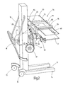
- a trolley 1 is illustrated for at least one needle board 2.
- the needle board 2 is a plate-shaped body having a plurality of felting needles 3 extending substantially at right angles from a flat side of the needle board 2 and held on the needle board 2.
- the needle board 2 has a rectangular outline with two short edges 4, 5 and two long edges 6, 7. It is held in a receiving device 8, which in turn is held by a base frame 9 of the trolley 1.
- This has a foot 10, from which a column 11 rises vertically.
- the foot 10 has, for example, two spars 12, 13 arranged at a distance from one another, which at their free ends carry rollers 14, 15 or, in place of them, also leveling feet. At its other end, the spars 12, 13 are interconnected and in turn provided with rollers 16, 17.
- For moving the trolley 1 serve one or more handles 18, 19, 20, as they are made FIG. 2 can be seen.
- the receiving device 8 is on the column 11 at a fixed height or, as is preferred, vertically (arrow V, in FIG. 1 ) arranged adjustable. The associated adjusting device is not further illustrated. Between the column 11 and the actual receiving device 8, an adjusting device 21 is arranged in the FIG. 1 closed and in FIG. 2 is shown with removed hood.
- the adjustment apparatus 21 permits an adjustment of the receiving device 8 by at least one, preferably by two axes 22, 23 (FIG. FIG. 1 ).
- the axis 22 is preferably approximately parallel to the short edges 4, 5 and is oriented horizontally. It is also referred to as a pivot axis.
- the axis 23 is preferably arranged horizontally and parallel to the long edges 6, 7 of the needle board 2. It is also called a tilt axis.
- the associated adjusting device 21 is schematically FIG. 8 out.
- a carrier 24 which is connected to a hollow shaft 25th is held. This is rotatably mounted in a bearing part 26.
- the bearing part 26 is connected directly or indirectly to the column 11.
- a shaft 27 which carries a bevel gear 28 at one end in a gap of the forked carrier 24 extends. This meshes with another bevel gear 29 which is rotatably connected to a shaft 30.
- the shaft 30 is arranged concentrically with the axis 23 and rotatably supported in the carrier 24 at both ends.
- the shaft 27 is arranged concentrically to the axis 22 and rotatably supported in the hollow shaft 25.
- the shaft 30 is rotatably connected to arms 31, 32 which carry the holding device 8.
- the bevel gear 28 remote end of the shaft 27 is connected by suitable transmission means, such as sprockets 33, 34 and a chain 35 with a gear 36 whose input shaft carries a handwheel 37.
- the transmission 36 is preferably a self-locking transmission, such as a worm gear.
- the sprocket 34 adjacent end of the hollow shaft 25 is also connected via a gear means, such as two sprockets 38, 39 and a chain 40 with a gear 41, whose input shaft carries a handwheel 42.
- the gear 41 is preferably a self-locking gear, such as a worm gear.
- the gear reduction of the respective actuator the handwheel 37, 42 to the respective output in the form of the carrier 24 and the arms 31, 32 is preferably twenty.
- the illustrated transmission means with worm gear, bevel gear and roller chain and other means, such as gear transmission, timing belt, drive shafts, lever mechanism or a combination of these transmission means may be used.
- the receiving device 8 has a frame 43 which has two mutually parallel, transversely to the second axis 23 extending support arms 44, 45. These are provided on their side facing the needle board 2 side, for example, with friction-reducing plastic pads.
- the frame 43 carries a receiving element 46, which according to FIGS. 2 to 6
- a receiving element 46 which according to FIGS. 2 to 6
- the rail 47 is adapted to the edge or the shape of the edge 6 of the needle board 2. It overlaps the edge of the needle board 2, wherein this in the rail 47 has so much game that it is parallel to her displaced.
- the rail 47 is opposite a receiving element in the form of a rail 48, which can serve as a locking means 49 to hold the needle board 2 in the receiving device 8 and secure.
- the rail 48 is preferably pivotally mounted about an axis 50 which is oriented parallel to the edge 7 of the needle board and thus parallel to the rails 47, 48.
- the rail 48 can thus between a holding position according to FIG. 3 and a release position according to FIG. 4 be panned.
- it can be locked in both pivot positions respectively.
- In two legs 52, 53 of the rail 48 each have a locking pin 54, 55 is mounted, which is movable in its longitudinal direction.
- the legs 52, 53 are mounted on receiving devices 56, 57 which are provided with holes into which the locking pins 54, 55 engage. As a result, the serving as a front terminal block rail 48 is fixed. Due to the arrangement of the holes, the two positions “holding position” or “closed position” and “release position” or “open position” are specified.
- the two locking pins 54, 55 are connected via two rods with a central knob 58. Depending on a knob 58 is arranged at each end of a shaft. This makes it accessible from two sides, which makes operation easier.
- the knob 58 is held by spring force in an angular position in which the locking pins 54, 55 engage in their holes. By turning the knob 90 °, the two rods pull the two locking pins 54, 55 out of the holes and the profile rail 48 can be pivoted. The angle of rotation of the knob 58 is limited by suitable stops.
- the receiving elements 46, 47 are held adjustably on the arms 44, 45 with respect to their longitudinal direction (see arrow in FIG. 6 ). By this linear adjustment of the distance between the rails 47, 48 can be adjusted as desired and thus adapted to different width needle boards 2.
- From the frame 43 extend preferably parallel to the long edge 6 of the needle board 2 telescopic arms 59, 60 in the opposite direction away from each other ( FIG. 1 ).
- the arms 60 are fixed by manually operable clamping lever 61, 62 in their respective setting positions.
- the mirror images of each other on the top of the arms 59, 60 arranged scales 63, 64 ( FIG. 2 ) indicate the set length of the arms 59, 60, which corresponds to a certain length of the needle board 2.
- the reading edge is formed by the boundary of the opening of the frame 43, in which the respective arm 59, 60 is to be inserted.
- the scaling is preferably dimensioned such that when the same values of the two arms 59, 60 are set, the needle board 2 is seated centrally in the receiving device 8.
- the arms 59, 60 carry at their ends stop units 65, 66, each representing a locking means 67, 68. This starts at the corners or, the short edges 4, 5 of the needle board 2 and serves as a longitudinal stop for the needle board 2.
- the stop unit 65 is in FIGS. 7a to 7d exemplified. It contains a guide body 69 in which a locking member in the form of a locking bolt 70 is mounted transversely to the direction indicated by an arrow 71 insertion direction of the needle board 2 movable.
- the locking pin 70 is biased by a spring means 72 in its locking position.
- the locking bolt 70 is preferably substantially cylindrical, wherein it may be provided on its side facing outwardly against the insertion direction side with an inclined surface 73.
- the frame 43 is associated with a protective cover 74 which is arranged and held parallel to the needle board 2. She is how FIG. 2 shows, held by two angled tubes 75, 76, whose ends are fixed to the frame 43.
- the protective cover 74 protects the needle board 2 from damage. In particular, the tips of the felting needles are protected from damage. In addition, the protective cover 74 offers personal protection. It prevents someone from accidentally reaching into the tips of the felting needles.
- the protective cover 74 is made according to FIG. 2 and 5 of three parts 77, 78, 79, wherein the parts 77 and 79 are identical.
- the protective cover 74 has transparent protective windows that are held in frames.
- the central part 78 is held in a frame 80.
- This has guide grooves, in which the parts 77, 79 are held displaceably.
- clamping means serve to secure the parts 77, 79 in their respective pull-out position.
- the length of the protective cover 74 of the length of the needle board 2 can be adjusted.
- the distance between the protective cover 74 and the needle board 2 can be made adjustable.
- the tubes 75, 76 sit on appropriate holders and be fixed by means of clamping screws 81.
- 81 corresponding locking means may be provided instead of the clamping screws.
- a needle board 2 are to be received in a horizontal position, with the needles point with the tips up, the frame 43 is rotated by actuation of the handwheels 37, 42, as in FIG. 2 is shown, ie the protective cover 74 is located above the frame 43.
- the front rail 48 is in its release position FIG. 4 pivoted.
- the trolley 1 is now moved so that the receiving device 8 is positioned below the male needle board 2.
- the receiving device 8 is raised by means of the lifting function, so that the needle board 2 is taken from its bearing. It now rests on all contact surfaces of the receiving device 8.
- the needle board 2 is then manually positioned between the two stop units 65, 66. If necessary, the Arms 59, 60 set to the needle board length.
- the needle board 2 is fixed in its longitudinal direction.
- the needle board 2 is pushed into the recess of the rear rail 47.
- the front rail 48 is after in its closed position FIG. 3 pivoted. Now the needle board 2 is fixed in all directions.
- the handwheel 42 is actuated. Because the gear 36 is self-locking, the shaft 27 does not rotate while the hollow shaft 25 is rotated. With the pivoting of the needle board 2 from its horizontal to the vertical position about the axis 22 is simultaneously a tilting movement about the axis 23, because the gear 29 rolls while on the fixed gear 28 from.
- the needle board 2 If the needle board 2 to be stored, it is pivoted by reverse operation of the hand wheel 42 back to horizontal position. The locking of the front profile rail 48 is opened. Thereafter, the needle board 2 located in the receiving device 8 is positioned above the desired bearing point. Subsequently, the needle board 2 is slightly pushed out of the U-shaped receptacle of the rear rail 47. It is now lowered with the trolley, the needle board 2, where it is then stored on its storage.
- the insertion movement of the needle board 2 is not carried out as previously described in the direction of the axis 22 but preferably in the direction of the axis 23.
- the frame 43 is brought into horizontal position.
- the rail 48 is in the closed position.
- the trolley 1 is positioned in such a position next to the placement machine, that the height and alignment of the needle board 2 in the placement machine coincides with the receiving device 8.
- the needle board 2 is horizontal in the placement machine.
- the needle points point down.
- the protective cover 74 is located below the frame 43, such as FIG. 1 suggests. Now the needle board 2 is manually pushed into the receiving device 8 of the trolley 1.
- the needle board 2 is in accordance with FIGS. 7a and 7b initially pushed to the stop unit 65 zoom.
- the front side of the needle board 2 at the edge 5 abuts against the inclined surface 73 and pushes the locking pin 70 aside, as it FIG. 7c shows. If the needle board 2 pushed further, it finds in the guide grooves of the rails 47, 48 and is pushed further until it abuts on the stop unit 66. The locking pin 70 of the stop unit 65 now jumps back into blocking position, as it FIG. 7d shows. The cylindrical surfaces of the two locking pins 70 of the two stop units 65, 66 hold the needle board 2 interlocked. The needle board 2 is now held securely and can be moved away in this position or after pivoting in the vertical position in its vertical position.
- the receiving device 8 in the horizontal position according to FIG. 1 brought.
- the trolley 1 is thereby positioned in such a way next to the placement machine, that the height and alignment of the receiving device of the trolley 1 and the receiving unit of the placement machine match.
- the locking pin 70 of that stop unit 65 or 66 is raised by hand, which is adjacent to the placement machine.
- the needle board 2 pushed into the placement machine, wherein the lifting of the locking bolt 70 is only necessary until its end face can rest on the edge of the needle board 2.
- Needle boards can also be performed in deviating from the horizontal position positions or tilting plies in the trolley 1 and out of this. Such tilting positions can be selectively adjusted by operating the handwheel 37.
- An inventive trolley 1 for needle boards 2 is provided with a receiving device 8 which is both adjustable in height and pivotable about at least one axis and which is associated with a protective cover, which is movable together with the receiving device. Numerous adjustment options, guiding and anchor devices are provided to handle large and heavy needle boards safely and gently.
Landscapes
- Engineering & Computer Science (AREA)
- Textile Engineering (AREA)
- Chemical & Material Sciences (AREA)
- Combustion & Propulsion (AREA)
- Transportation (AREA)
- Mechanical Engineering (AREA)
- Handcart (AREA)
- Treatment Of Fiber Materials (AREA)
- Portable Nailing Machines And Staplers (AREA)
- Infusion, Injection, And Reservoir Apparatuses (AREA)
- Vehicle Step Arrangements And Article Storage (AREA)
- Nonwoven Fabrics (AREA)
Abstract
Description
Die Erfindung betrifft einen Transportwagen zum Transport und für das Handling von Nadelbrettern, wie sie in Filzmaschinen in Gebrauch sind.The invention relates to a trolley for the transport and handling of needle boards, as they are in felting machines in use.
Zur Filzherstellung werden Filzmaschinen genutzt, die Nadelbretter aufweisen. Ein solches Nadelbrett ist ein großes plattenförmiges Bauteil, das mit einer Vielzahl von Filznadeln bestückt ist, die von einer Fläche dieser Platte weg stehen. Während in einer Filzmaschine ein oder mehrere solcher Nadelbretter zur Anwendung kommen, werden Nadelbretter meist in größerer Zahl an einem Lagerort bereitgehalten, um bei Bedarf in die Filzmaschine eingesetzt und aus dieser herausgeführt zu werden. Filznadeln sind Verschleißteile. Deshalb müssen die Filznadeln der Nadelbretter gelegentlich gewechselt werden. Dazu dienen entsprechende Bestückungsautomaten, in die die Nadelbretter bedarfsweise zu überführen und aus denen die Nadelbretter abzutransportieren sind. Die Nadelbretter können ein erhebliches Gewicht von mehreren Kilogramm z.B. 50 kg und darüber und große Abmessungen aufweisen. Die Filznadeln sind einerseits relativ empfindlich. Sie dürfen weder während des Transports noch während der Lagerung beschädigt werden. Schon eine leichte Verbiegung einer oder mehrerer Filznadeln kann nicht hingenommen werden. Andererseits sind die Filznadeln häufig sehr spitz, scharfkantig und/oder mit Widerhaken versehen, so dass von ihnen eine erhebliche Verletzungsgefahr ausgeht.For felting felt machines are used, which have needle boards. Such a needle board is a large plate-shaped member which is equipped with a plurality of felting needles, which stand away from a surface of this plate. While one or more such needle boards are used in a felting machine, needle boards are usually kept in greater numbers at a storage location in order to be inserted into and removed from the felting machine as needed. Felting needles are wearing parts. Therefore, the felt needles of the needle boards must be changed occasionally. Serve with appropriate pick and place machines, in which the needle boards need to be transferred and from which the needle boards are to be removed. The needle boards can have a considerable weight of several kilograms, e.g. 50 kg and above and have large dimensions. The felting needles are on the one hand relatively sensitive. They must not be damaged during transport or during storage. Even a slight bending of one or more felting needles can not be accepted. On the other hand, the felting needles are often very pointed, sharp-edged and / or barbed, so that they pose a significant risk of injury.
Es ist Aufgabe der Erfindung, eine Möglichkeit für den schonenden und gefahrlosen Transport der Nadelbretter anzugeben.It is an object of the invention to provide a way for the gentle and safe transport of needle boards.
Diese Aufgabe wird mit dem Transportwagen nach Anspruch 1 gelöst:
- Der erfindungsgemäße Transportwagen weist ein Grundgestell mit Laufrädern auf, so dass er auf einem Hallenboden von Hand oder gegebenenfalls auch mittels einer angebauten oder zugehörigen Antriebseinrichtung verfahren werden kann. Die Laufräder sind vorzugsweise freilaufend. Einem oder mehreren von ihnen können auch Antriebseinrichtungen, Bremseinrichtungen und dergleichen zugeordnet sein.
- The trolley according to the invention has a base frame with wheels, so that it can be moved on an indoor floor by hand or possibly also by means of a mounted or associated drive device. The wheels are preferably free-running. One or more of them may also be associated with drive devices, brake devices and the like.
Das Grundgestell des Transportwagens trägt eine Aufnahmeeinrichtung für ein Nadelbrett. Diese Aufnahmeeinrichtung weist mindestens ein an den Rand des Nadelbretts angepasstes Aufnahmeelement und mindestens ein Arretierungsmittel auf, um das Nadelbrett in der Aufnahmeeinrichtung zu sichern. Dadurch wird ermöglicht, dass das Nadelbrett nur an seinen Rändern gefasst und die Fläche, von der die vielen Filznadeln weg ragen, nicht berührt wird. Die Aufnahmeeinrichtung ist somit dazu eingerichtet, das Nadelbrett an seinem Rand zu ergreifen und zu erfassen. Außerdem weist die Aufnahmeeinrichtung ein Arretierungsmittel auf, das dazu eingerichtet ist, das Nadelbrett in einer Aufnahmeposition zu sichern. Damit kann ein Nadelbrett beispielsweise an einem Lagerort aufgenommen und von dort zu einem Bestückungsautomaten oder einer Filzmaschine gefahren werden, ohne dass dabei die Gefahr besteht, dass das Nadelbrett beschädigt wird oder Menschen verletzt. Ebenso kann das Nadelbrett an einem Bestückungsautomaten oder einer Filzmaschine aufgenommen werden, um an einen anderen Ort verfahren zu werden.The base frame of the trolley carries a receiving device for a needle board. This receiving device has at least one adapted to the edge of the needle board receiving element and at least one locking means to secure the needle board in the receiving device. This allows the needle board to be grasped only at its edges and not to touch the area from which the many felting needles protrude. The receiving device is thus configured to grasp and grasp the needle board at its edge. In addition, the receiving device has a locking means which is adapted to secure the needle board in a receiving position. This allows a needle board, for example, taken at a storage location and driven from there to a placement machine or a felting machine, without causing the risk that the needle board is damaged or injured people. Likewise, the needle board can be added to a placement machine or a felting machine to be moved to another location.
Vorzugsweise ist die Aufnahmeeinrichtung an dem Grundgestell in zumindest einer Richtung verstellbar gelagert. Diese Richtung ist beispielsweise die Vertikalrichtung. Dies erleichtert die Übergabe des Nadelbretts an eine Filzmaschine oder einen Bestückungsautomaten. Die Aufnahmeeinrichtung wird dann einfach in diejenige Höhe verfahren, in der das Nadelbrett in den Bestückungsautomaten oder die Filzmaschine eingesetzt werden soll und auf horizontalem Weg aus der Aufnahmeeinrichtung in die Filzmaschine oder den Bestückungsautomaten übergeben. Dies erleichtert die Arbeit des Bedieners, insbesondere wenn das Nadelbrett ein hohes Gewicht aufweist. Zur Vertikalverstellung kann eine hydraulische Hebeeinrichtung, ein Spindelhubgetriebe oder dergleichen mit Handantrieb oder Motorantrieb dienen.Preferably, the receiving device is mounted on the base frame in at least one direction adjustable. These Direction is, for example, the vertical direction. This facilitates the transfer of the needle board to a felting machine or a pick and place machine. The receiving device is then simply moved to that height in which the needle board is to be used in the placement machine or the felting machine and transferred horizontally from the receiving device in the felting machine or the placement machine. This facilitates the work of the operator, especially when the needle board has a high weight. For vertical adjustment can serve a hydraulic lifting device, a screw jack or the like with manual or motor drive.
Vorzugsweise ist die Aufnahmeeinrichtung bezüglich des Grundgestells um zumindest eine Achse schwenkbar gelagert. Bei dieser Achse handelt es sich vorzugsweise um eine Horizontalachse, die quer zu den langen Kanten des Nadelbretts und vorzugsweise etwa parallel zu den kurzen Kanten des Nadelbretts orientiert ist. Auf diese Weise kann ein von der Aufnahmeeinrichtung aufgenommenes Nadelbrett, das beispielsweise eine Länge von zwei Metern hat, in eine Vertikalposition geschwenkt werden, um es leicht transportieren zu können. So ist der Transport auch bei beengten räumlichen Verhältnissen am Einsatzort möglich.Preferably, the receiving device is mounted pivotably relative to the base frame about at least one axis. This axis is preferably a horizontal axis oriented transverse to the long edges of the needle board and preferably approximately parallel to the short edges of the needle board. In this way, a recorded by the receiving device needle board, for example, has a length of two meters, are pivoted to a vertical position to easily transport it. So the transport is possible even in confined space conditions at the place of use.
Die Aufnahmeeinrichtung ist vorzugsweise bezüglich des Grundgestells um zumindest eine zweite Achse schwenkbar gelagert, die auch als Kippachse bezeichnet werden kann. Diese Kippachse ist vorzugsweise parallel zu einer langen Kante des Nadelbretts und somit quer, vorzugsweise rechtwinklig zu der ersten Achse orientiert. Vorzugsweise verläuft die zweite Schwenkachse in der Nähe des Aufnahmeelements, d.h. in der Nähe einer langen Kante des Nadelbretts. Damit lässt sich das Nadelbrett in eine Vertikalposition oder auch in eine Schrägposition überführen, in der es beispielsweise in einen Bestückungsautomaten zu überführen ist.The receiving device is preferably pivotally mounted relative to the base frame about at least a second axis, which may also be referred to as a tilting axis. This tilting axis is preferably oriented parallel to a long edge of the needle board and thus transversely, preferably at right angles to the first axis. Preferably, the second pivot axis extends in the vicinity of the receiving element, ie in the vicinity of a long edge of the needle board. Thus, the needle board can be converted into a vertical position or in a slanted position, in which it, for example, in a placement machine to convict.
Vorzugsweise ist zumindest eine Betätigungseinrichtung vorgesehen, mit der die Aufnahmeeinrichtung gezielt um die erste und/oder die zweite Achse verschwenkt werden kann. Die Betätigungseinrichtung ist vorzugsweise eine Handbetätigungseinrichtung - es kann aber auch ein Motorantrieb vorgesehen werden. Vorzugsweise ist die Betätigungseinrichtung selbstsperrend, d.h. sie hält die Aufnahmeeinrichtung weitgehend unabhängig von auf die Aufnahmeeinrichtung einwirkenden Kräften in einer einmal eingestellten Position. Beispielsweise enthält die Betätigungseinrichtung ein Schneckengetriebe oder ein anderes selbstsperrendes Getriebe, mit dem die Kraft von einem Betätigungsorgan, beispielsweise einem Handrad, auf die Aufnahmeeinrichtung übertragen wird.Preferably, at least one actuating device is provided, with which the receiving device can be selectively pivoted about the first and / or the second axis. The actuator is preferably a manual actuator - but it can also be provided a motor drive. Preferably, the actuator is self-locking, i. it holds the receiving device largely independent of forces acting on the receiving device forces in a once set position. For example, the actuator includes a worm gear or other self-locking gear, with which the force is transmitted from an actuator, such as a handwheel, on the receiving device.
Vorzugsweise ist eine Betätigungseinrichtung vorgesehen, die bei Betätigung eine Schwenkbewegung der Aufnahmeeinrichtung sowohl um die erste Achse wie auch um die zweite Achse bewirkt. Dadurch kann das Nadelbrett durch Bedienung einer einzigen Betätigungseinrichtung aus einer Aufnahmeposition in eine Transportposition geschwenkt werden. In der Aufnahmepositioh ist das Nadelbrett beispielsweise horizontal gehalten während es in der Transportposition vertikal gehalten ist. Mit anderen Worten, der Transportwagen weist eine Verstelleinrichtung auf, mit der die Aufnahmeeinrichtung zwischen einer vorzugsweise wählbaren Aufnahmeposition für das Nadelbrett und einer Transportposition für das Nadelbrett verstellt werden kann. Die Aufnahmeposition unterscheidet sich von der Transportposition vorzugsweise um eine Drehung um 90° um zumindest eine der beiden Achsen. Während das Nadelbrett flach liegend aufgenommen und abgegeben werden kann, wird es in aufrecht stehender Position transportiert.Preferably, an actuating device is provided which causes a pivoting movement of the receiving device both on the first axis as well as about the second axis when actuated. Thereby, the needle board can be pivoted by operation of a single actuator from a receiving position to a transport position. In the Aufnahmeepositioh the needle board is for example kept horizontal while it is held vertically in the transport position. In other words, the transport carriage has an adjusting device with which the receiving device can be adjusted between a preferably selectable receiving position for the needle board and a transport position for the needle board. The receiving position preferably differs from the transport position by a rotation through 90 ° about at least one of the two axes. While the needle board can be picked up and delivered lying flat, it is transported in an upright position.
Das Aufnahmeelement wird beispielsweise durch eine erste Profilschiene gebildet, die z.B. an einer der langen Kanten des Nadelbretts vorzugsweise lediglich in einem mittleren Abschnitt derselben ansetzt. Zu dem Aufnahmemittel gehört außer dem Aufnahmeelement, d.h. beispielsweise der Profilschiene, das Arretierungsmittel, das ebenfalls als Profilschiene ausgebildet sein kann. Auch diese zweite Profilschiene fasst das Nadelbrett vorzugsweise an seiner langen Kante. Vorzugsweise ist die zweite Profilschiene in ihrem Abstand zu der ersten Profilschiene einstellbar ausgebildet, um eine Anpassung an verschiedene Nadelbrettbreiten zu gestatten. Außerdem ist die zweite Profilschiene vorzugsweise schwenkbar gelagert, um zwischen einer Halteposition und einer Freigabeposition verstellt werden zu können. Vorzugsweise ist sie in beiden Positionen arretierbar. Das Verschwenken der zweiten Profilschiene zwischen Halteposition und Freigabeposition erfolgt vorzugsweise um eine zu der langen Kante des Nadelbretts parallelen Schwenkachse. Dadurch kann das Nadelbrett sowohl parallel zu seinen langen Kanten als auch wahlweise quer zu diesen in die Aufnahmeeinrichtung hinein und aus dieser heraus geführt werden.The receiving element is, for example, by a first Profile rail formed, for example, attaches to one of the long edges of the needle board preferably only in a central portion thereof. To the receiving means belongs except the receiving element, ie, for example, the rail, the locking means, which may also be formed as a profile rail. This second profile rail also holds the needle board preferably at its long edge. Preferably, the second rail is formed adjustable in its distance from the first rail to allow adaptation to different Nadelbrettbreiten. In addition, the second rail is preferably pivotally mounted to be able to be adjusted between a holding position and a release position can. Preferably, it is lockable in both positions. The pivoting of the second rail between the holding position and release position is preferably carried out about a parallel to the long edge of the needle board pivot axis. As a result, the needle board can be guided both parallel to its long edges and optionally transversely to these in the receiving device and out of this.
Die Arretierungsmittel sind vorzugsweise an einer kurzen Kante und/oder an einer Ecke des Nadelbretts angeordnet. Z.B. werden die Arretierungsmittel durch beweglich gelagerte, beispielsweise nach Art von Rastmitteln ausgebildete Sperrglieder gebildet, die von teleskopierbaren Armen getragen werden, die sich von der Aufnahmeeinrichtung weg erstrecken. Die Sperrglieder können senkrecht zur Flachseite des Nadelbretts beweglich gelagert und auf ihrer Sperrstellung federnd vorgespannt sein. Weisen sie an ihrer dem Nadelbrett zugewandten Seite eine quer zur Verschieberichtung des Nadelbretts stehende Sperrfläche und an der dem Nadelbrett abgewandten Seite eine Schrägfläche auf, können sie, wenn das Nadelbrett in die Aufnahmeeinrichtung parallel zur Längskante eingeschoben werden soll, von dem Nadelbrett bei Seite geschoben werden, wobei sie dann hinter dem Nadelbrett einrasten und dieses arretieren.The locking means are preferably arranged on a short edge and / or on a corner of the needle board. For example, the locking means are formed by movably mounted, for example in the manner of locking means formed locking members which are supported by telescopic arms which extend away from the receiving device. The locking members can be mounted to be movable perpendicular to the flat side of the needle board and resiliently biased in its blocking position. If they have on their side facing the needle board a transverse to the direction of the needle board locking surface and on the side facing away from the needle board an inclined surface, they can, if the needle board is to be inserted into the receiving device parallel to the longitudinal edge of the needle board by side , in which Then they lock behind the needle board and lock it.
Weitere Einzelheiten vorteilhafter Ausführungsformen ergeben sich aus Ansprüchen, der Zeichnung oder der Beschreibung. Die Beschreibung beschränkt sich auf wesentliche Aspekte der Erfindung und sonstiger Gegebenheiten. Die Zeichnung offenbart weitere Details und ergänzt die Beschreibung. Es zeigen:
-
Figur 1 -
Figur 2Transportwagen nach Figur 1 in perspektivischer Gesamtansicht mit seiner Aufnahmeeinrichtung in einer zweiten Horizontalposition, -
Figur 3 die Aufnahmeeinrichtung des Transportwagens nachFigur 1 in Halteposition in perspektivischer Darstellung, -
Figur 4 die Aufnahmeeinrichtung mit Nadelbrett in Freigabeposition in perspektivischer Darstellung, -
Figur 5 -
Figur 6 -
Figur 7a bis 7d eine Rasteinrichtung als Arretierungsmittel für das Nadelbrett in gesonderter schematischer Darstellung und verschiedenen Rastpositionen und -
Figur 8
-
FIG. 1 the trolley according to the invention with needle board in a perspective overall view with its receiving device in a first horizontal position, -
FIG. 2 the trolley afterFIG. 1 in a perspective overall view with its receiving device in a second horizontal position, -
FIG. 3 the receiving device of the trolley afterFIG. 1 in holding position in perspective, -
FIG. 4 the receiving device with needle board in the release position in perspective view, -
FIG. 5 the receiving device with protective cover and needle board in a separate perspective view, -
FIG. 6 the recording device in fragmentary sketchy side view, -
FIGS. 7a to 7d a locking device as a locking means for the needle board in a separate schematic representation and various locking positions and -
FIG. 8 the actuating device for pivoting the receiving device in a schematic diagram.
In
Die Aufnahmeeinrichtung 8 ist an der Säule 11 in fester Höhe oder, wie es bevorzugt wird, vertikal (Pfeil V, in
Das dem Kegelrad 28 entfernt liegende Ende der Welle 27 ist durch geeignete Getriebemittel, beispielsweise Kettenräder 33, 34 und eine Kette 35 mit einem Getriebe 36 verbunden, dessen Eingangswelle ein Handrad 37 trägt. Das Getriebe 36 ist vorzugsweise ein selbstsperrendes Getriebe, beispielsweise ein Schneckengetriebe.The
Das dem Kettenrad 34 benachbarte Ende der Hohlwelle 25 ist ebenfalls über ein Getriebemittel, beispielsweise zwei Kettenräder 38, 39 und eine Kette 40 mit einem Getriebe 41 verbunden, dessen Eingangswelle ein Handrad 42 trägt. Das Getriebe 41 ist vorzugsweise ein selbsthemmendes Getriebe, beispielsweise ein Schneckengetriebe. Insgesamt ist die Getriebeuntersetzung von der jeweiligen Betätigungseinrichtung dem Handrad 37, 42 bis zu dem jeweiligen Abtrieb in Gestalt des Trägers 24 bzw. der Arme 31, 32 vorzugsweise gleich zwanzig. An Stelle der dargestellten Getriebemittel mit Schneckengetriebe, Kegelradgetriebe und Rollenkette können auch andere Mittel, wie Zahnradgetriebe, Zahnriemen, Gelenkwellen, Hebelgetriebe oder eine Kombination dieser Übertragungsmittel zur Anwendung kommen.The
Die Aufnahmeeinrichtung 8 weist einen Rahmen 43 auf, der zwei zueinander parallele, sich quer zu der zweiten Achse 23 erstreckende Auflagearme 44, 45 aufweist. Diese sind an ihrer dem Nadelbrett 2 zugewandten Seite beispielsweise mit reibungsmindernden Kunststoffauflagen versehen. Der Rahmen 43 trägt ein Aufnahmeelement 46, das gemäß
Der Profilschiene 47 liegt ein Aufnahmeelement in Form einer Profilschiene 48 gegenüber, die als Arretierungsmittel 49 dienen kann, um das Nadelbrett 2 in der Aufnahmeeinrichtung 8 zu halten und zu sichern. Die Profilschiene 48 ist vorzugsweise um eine Achse 50 schwenkbar gelagert, die parallel zu dem Rand 7 des Nadelbretts und somit parallel zu den Profilschienen 47, 48 orientiert ist. Wie in
Die Aufnahmeelemente 46, 47 sind an den Armen 44, 45 bezüglich deren Längsrichtung verstellbar gehalten (siehe Pfeil in
Von dem Rahmen 43 erstrecken sich vorzugsweise parallel zu der langen Kante 6 des Nadelbretts 2 teleskopierbare Arme 59, 60 in Gegenrichtung voneinander weg (
Die Arme 59, 60 tragen an ihren Enden Anschlageinheiten 65, 66, die jeweils ein Arretiermittel 67, 68 darstellen. Dieses setzt an den Ecken bzw, den kurzen Kanten 4, 5 des Nadelbretts 2 an und dient als Längsanschlag für das Nadelbrett 2. Die Anschlageinheit 65 ist in
Dem Rahmen 43 ist eine Schutzabdeckung 74 zugeordnet, die parallel zu dem Nadelbrett 2 angeordnet und gehalten ist. Sie ist, wie
Die Schutzabdeckung 74 besteht gemäß
Der insoweit beschriebene Transportwagen 1 arbeitet wie folgt:
Der Transportwagen 1 wird bei Bedarf zunächst in seiner Höhe eingestellt.Die Aufnahmeeinrichtung 8 kann dabei beispielsweise hydraulisch oder auch durch eine Schraubspindel oder dergleichen Mittel verstellt werden. Beispielsweise kann der Handgriff 18 als Pumpenhebel dienen, mit dem man die Hubfunktion in Kraft setzt. Zum Absenken kann ein Ablassventil mittels eines Drehknopfs geöffnet werden. Dieser kann federnd gelagert sein, so dass beim Loslassen des Drehknopfs dieser automatisch in Sperrstellung übergeht und das Ablassventil geschlossen wird.
- The
trolley 1 is initially adjusted in height if necessary. The receivingdevice 8 can be adjusted for example hydraulically or by a screw or the like means. For example, thehandle 18 serve as a pump lever, with which one puts the lifting function in place. To lower a drain valve can be opened by means of a knob. This can be resiliently mounted so that when you release the knob this automatically goes into blocking position and the drain valve is closed.
Soll ein Nadelbrett 2 in horizontaler Lage aufgenommen werden, wobei die Nadeln mit den Spitzen nach oben zeigen, wird der Rahmen 43 durch Betätigung der Handräder 37, 42 so gedreht, wie er in
Soll es transportiert werden, wird es aus seiner Horizontallage in die Vertikallage geschwenkt. Dazu wird das Handrad 42 betätigt. Weil das Getriebe 36 selbstsperrend ist, dreht die Welle 27 dabei nicht während die Hohlwelle 25 gedreht wird. Mit dem Schwenken des Nadelbretts 2 aus seiner Horizontal- in die Vertikalposition um die Achse 22 erfolgt gleichzeitig eine Kippbewegung um die Achse 23, denn das Zahnrad 29 rollt dabei an dem feststehenden Zahnrad 28 ab.If it is to be transported, it is pivoted from its horizontal position to the vertical position. For this purpose, the
Dadurch wird der Schwerpunkt des Nadelbretts nahe an die Säule 11 heran gebracht, wodurch die erforderliche und gewünschte Standfestigkeit des Transportwagens 1 erreicht oder unterstützt wird.As a result, the center of gravity of the needle board is brought close to the
Soll das Nadelbrett 2 abgelegt werden, wird es durch umgekehrte Betätigung des Handrads 42 wieder in Horizontallage geschwenkt. Es wird die Verriegelung der vorderen Profilschiene 48 geöffnet. Danach wird das in der Aufnahmeeinrichtung 8 befindliche Nadelbrett 2 über der gewünschten Lagerstelle positioniert. Anschließend wird das Nadelbrett 2 aus der u-förmigen Aufnahme der hinteren Profilschiene 47 etwas herausgeschoben. Es wird nun mit dem Transportwagen das Nadelbrett 2 abgesenkt, wobei es dann auf seiner Lagerstelle abgelegt wird.If the
Soll das Nadelbrett 2 aus einem Bestückungsautomaten übernommen werden, erfolgt die Einschubbewegung des Nadelbretts 2 nicht wie bislang beschrieben in Richtung der Achse 22 sondern vorzugsweise in Richtung der Achse 23. Dazu wird der Rahmen 43 in Horizontallage gebracht. Die Profilschiene 48 befindet sich in Schließstellung. Der Transportwagen 1 wird derart neben dem Bestückungsautomaten positioniert, dass die Höhe und Flucht des Nadelbretts 2 in dem Bestückungsautomaten mit der Aufnahmeeinrichtung 8 übereinstimmt. Das Nadelbrett 2 liegt waagerecht in dem Bestückungsautomaten. Die Nadelspitzen weisen nach unten. Die Schutzabdeckung 74 befindet sich unterhalb des Rahmens 43, wie
Soll das Nadelbrett 2 in dem Bestückungsautomaten abgelegt werden, wird die Aufnahmeeinrichtung 8 in die Horizontalposition gemäß
Nadelbretter können auch in von der Horizontalposition abweichenden Positionen bzw. Kipplagen in den Transportwagen 1 und aus diesem heraus geführt werden. Solche Kipplagen können durch Betätigung des Handrads 37 wahlweise eingestellt werden.Needle boards can also be performed in deviating from the horizontal position positions or tilting plies in the
Ein erfindungsgemäßer Transportwagen 1 für Nadelbretter 2 ist mit einer Aufnahmeeinrichtung 8 versehen, die sowohl höhenverstellbar als auch um zumindest eine Achse schwenkbar ausgebildet ist und der eine Schutzabdeckung zugeordnet ist, die gemeinsam mit der Aufnahmeeinrichtung beweglich ist. Zahlreiche Einstellmöglichkeiten, Führungs- und Anschlageinrichtungen sind vorgesehen, um auch große und schwere Nadelbretter sicher und schonend handhaben zu können.An
- 11
- TransportwagenDolly
- 22
- Nadelbrettneedle board
- 33
- Filznadelnfelting needles
- 4, 54, 5
- kurze Kanten des Nadelbrettsshort edges of the needle board
- 6, 76, 7
- lange Kanten des Nadelbrettslong edges of the needle board
- 88th
- Aufnahmeeinrichtungrecording device
- 99
- Grundgestellbase frame
- 1010
- Fußfoot
- 1111
- Säulepillar
- 12, 1312, 13
- HolmeHolme
- 14, 15, 16, 1714, 15, 16, 17
- Rollen, LaufräderRollers, wheels
- 18, 19, 2018, 19, 20
- Handgriffhandle
- 2121
- Verstellapparatadjustment device
- 2222
- erste Achsefirst axis
- 2323
- zweite Achsesecond axis
- 2424
- Trägercarrier
- 2525
- Hohlwellehollow shaft
- 2626
- Lagerteilbearing part
- 2727
- Wellewave
- 28, 2928, 29
- Kegelradbevel gear
- 3030
- Wellewave
- 31, 3231, 32
- Armepoor
- 33, 3433, 34
- Kettenrädersprockets
- 3535
- KetteChain
- 3636
- Getriebetransmission
- 3737
- Betätigungseinrichtung, HandradActuating device, handwheel
- 38, 3938, 39
- Kettenrädersprockets
- 4040
- KetteChain
- 4141
- Getriebetransmission
- 4242
- Betätigungseinrichtung, HandradActuating device, handwheel
- 4343
- Rahmenframe
- 44, 4544, 45
- Auflagearmesupport arms
- 4646
- Aufnahmeelementreceiving element
- 47, 4847, 48
- Profilschienerail
- 4949
- Arretierungsmittellocking
- 5050
- Achseaxis
- 5151
- Arretierungseinrichtunglocking device
- 52, 5352, 53
- Schenkelleg
- 54, 5554, 55
- Schließbolzenlocking pin
- 56, 5756, 57
- Aufnahmevorrichtungencradles
- 5858
- Drehknopfknob
- 59, 6059, 60
- Armepoor
- 61, 6261, 62
- Klemmhebelclamping lever
- 63, 6463, 64
- Skalierungenscaling
- 65, 6665, 66
- Anschlageinheitenstop units
- 67, 6867, 68
- Arretiermittellocking
- 6969
- Führungskörperguide body
- 7070
- Verriegelungsbolzenlocking bolt
- 7171
- Einschieberichtunginsertion
- 7272
- Federmittelspring means
- 7373
- Schrägflächesloping surface
- 7474
- Schutzabdeckungprotective cover
- 75, 7675, 76
- RohreTube
- 77, 78, 7977, 78, 79
- Teile der SchutzabdeckungParts of the protective cover
- 8080
- Rahmenframe
- 8181
- Klemmschraubenclamping screws
Claims (11)
mit einem Grundgestell (9), das Laufräder (14, 15, 16, 17) aufweist,
mit einer Aufnahmeeinrichtung (8) für das Nadelbrett (2), die mindestens ein an den Rand (6) des Nadelbretts (2) angepasstes Aufnahmeelement (46) und mindestens ein Arretierungsmittel (49, 67) aufweist, um das Nadelbrett (2) in der Aufnahmeeinrichtung (43) zu sichern.Transport trolley (1) for a needle board (2)
with a base frame (9) having running wheels (14, 15, 16, 17),
with a receiving device (8) for the needle board (2), which has at least one receiving element (46) adapted to the edge (6) of the needle board (2) and at least one locking means (49, 67) for moving the needle board (2) into to secure the receiving device (43).
Priority Applications (12)
| Application Number | Priority Date | Filing Date | Title |
|---|---|---|---|
| PL07017873T PL2037030T3 (en) | 2007-09-12 | 2007-09-12 | Transport cart for needle boards |
| EP07017873A EP2037030B1 (en) | 2007-09-12 | 2007-09-12 | Transport cart for needle boards |
| DE502007004733T DE502007004733D1 (en) | 2007-09-12 | 2007-09-12 | Transport trolley for needle boards |
| AT07017873T ATE477362T1 (en) | 2007-09-12 | 2007-09-12 | TRANSPORT TROLLEY FOR NEEDLE BOARDS |
| ES07017873T ES2349440T3 (en) | 2007-09-12 | 2007-09-12 | TRANSPORT CART FOR NEEDLE TABLES. |
| BRPI0802668-8A BRPI0802668A2 (en) | 2007-09-12 | 2008-08-26 | transport cart for a needle plate |
| JP2008233774A JP4772093B2 (en) | 2007-09-12 | 2008-09-11 | Transport cart for needle board |
| KR1020080089627A KR101135376B1 (en) | 2007-09-12 | 2008-09-11 | Transport cart for needle boards |
| CN2008102138468A CN101387055B (en) | 2007-09-12 | 2008-09-11 | Transport cart for needle boards |
| TW097134785A TWI363113B (en) | 2007-09-12 | 2008-09-11 | Transport cart for needle boards |
| US12/232,127 US7954214B2 (en) | 2007-09-12 | 2008-09-11 | Transport cart for needle boards |
| RU2008144436/12A RU2401334C2 (en) | 2007-09-12 | 2008-11-10 | Transport trolley for needle boards |
Applications Claiming Priority (1)
| Application Number | Priority Date | Filing Date | Title |
|---|---|---|---|
| EP07017873A EP2037030B1 (en) | 2007-09-12 | 2007-09-12 | Transport cart for needle boards |
Publications (2)
| Publication Number | Publication Date |
|---|---|
| EP2037030A1 true EP2037030A1 (en) | 2009-03-18 |
| EP2037030B1 EP2037030B1 (en) | 2010-08-11 |
Family
ID=38984288
Family Applications (1)
| Application Number | Title | Priority Date | Filing Date |
|---|---|---|---|
| EP07017873A Not-in-force EP2037030B1 (en) | 2007-09-12 | 2007-09-12 | Transport cart for needle boards |
Country Status (12)
| Country | Link |
|---|---|
| US (1) | US7954214B2 (en) |
| EP (1) | EP2037030B1 (en) |
| JP (1) | JP4772093B2 (en) |
| KR (1) | KR101135376B1 (en) |
| CN (1) | CN101387055B (en) |
| AT (1) | ATE477362T1 (en) |
| BR (1) | BRPI0802668A2 (en) |
| DE (1) | DE502007004733D1 (en) |
| ES (1) | ES2349440T3 (en) |
| PL (1) | PL2037030T3 (en) |
| RU (1) | RU2401334C2 (en) |
| TW (1) | TWI363113B (en) |
Cited By (2)
| Publication number | Priority date | Publication date | Assignee | Title |
|---|---|---|---|---|
| EP2223884A1 (en) * | 2009-02-27 | 2010-09-01 | Groz-Beckert KG | Transport cart for needle boards |
| WO2015063328A1 (en) * | 2013-11-04 | 2015-05-07 | Autefa Solutions Germany Gmbh | Automatic needle placement machine and automatic placement method |
Families Citing this family (8)
| Publication number | Priority date | Publication date | Assignee | Title |
|---|---|---|---|---|
| AU2010225977B2 (en) | 2009-03-19 | 2013-01-24 | Ishigaki Company Limited | Concentrator-integrated screw press |
| JP5802430B2 (en) * | 2011-05-13 | 2015-10-28 | 株式会社岡村製作所 | Cart equipment |
| US20150251883A1 (en) * | 2014-03-10 | 2015-09-10 | Arnaldo Miranda | Automotive Hydraulic Tilt Lift Assembly and Related Methods |
| CN106143559B (en) * | 2016-08-15 | 2018-08-24 | 唐山文丰山川轮毂有限公司 | A kind of packaged type maintenance trolley with lifting foot support |
| CN108754900A (en) * | 2018-07-26 | 2018-11-06 | 吴江市震宇缝制设备有限公司 | A kind of use in sewing machine needle protection |
| KR102442105B1 (en) * | 2020-11-27 | 2022-09-07 | 문철규 | carrying device for drum |
| CN113104079B (en) * | 2021-05-13 | 2023-01-31 | 安徽省巢湖市锐镱内燃机配件有限公司 | Service trolley with adjustable model |
| CN114348612B (en) * | 2021-12-31 | 2023-07-04 | 苏州富强科技有限公司 | Alternate lifting type stock bin assembly |
Citations (4)
| Publication number | Priority date | Publication date | Assignee | Title |
|---|---|---|---|---|
| DE3941159A1 (en) * | 1988-12-14 | 1990-06-28 | Offermann Zeiler Schmid Bwf | Procedure and appts. to fit or remove needles from needle board - with devices to automatically ensure correct alignment of needle |
| DE4224038A1 (en) * | 1991-07-31 | 1993-02-04 | Fehrer Textilmasch | DEVICE FOR CHANGING THE NEEDLE BOARDS OF A NEEDLE DEVICE FOR FLEECE |
| DE19640751A1 (en) * | 1995-10-18 | 1997-04-24 | Fehrer Textilmasch | Device for needling a fleece |
| DE10021547A1 (en) * | 1999-05-31 | 2000-12-07 | Fehrer Textilmasch | Appts to change needle boards at a needle bonding machine for nonwovens has centering pins at the step conveyor which engage centering bushes at the needle board for accurate positioning and alignment |
Family Cites Families (13)
| Publication number | Priority date | Publication date | Assignee | Title |
|---|---|---|---|---|
| US2706056A (en) * | 1952-01-23 | 1955-04-12 | United Merchants & Mfg | Warp beam truck |
| US3486650A (en) * | 1968-04-08 | 1969-12-30 | Byron F Boone | Heavy mover apparatus |
| US3574907A (en) * | 1969-02-26 | 1971-04-13 | Anvar | Device for supporting and handling warp beams in cloth mills |
| US4512473A (en) * | 1982-12-02 | 1985-04-23 | Ppg Industries, Inc. | Adjustable shipping container for frangible sheet-like units |
| CA2028669C (en) * | 1990-10-26 | 1995-09-26 | Gary L. Ingram | Tufting apparatus |
| US5018930A (en) * | 1990-03-12 | 1991-05-28 | Sid Corp., Inc. | Lifting and transporting device |
| GB9701446D0 (en) * | 1997-01-24 | 1997-03-12 | Scapa Group Plc | Warp changing apparatus |
| JP2000110061A (en) * | 1998-10-05 | 2000-04-18 | Toray Ind Inc | Needle board maintenance dolly |
| US6003215A (en) * | 1998-12-01 | 1999-12-21 | Morrison Berkshire, Inc. | Apparatus for replacement of needle boards in a needle loom |
| US6145176A (en) * | 1999-05-28 | 2000-11-14 | Morrison Berkshire, Inc. | Apparatus for replacement and alignment of needle boards in a needle loom |
| US6186728B1 (en) * | 1999-10-06 | 2001-02-13 | Rino Michaud | Lift truck |
| FR2824084B1 (en) * | 2001-04-30 | 2003-08-01 | Messier Bugatti | NEEDLE FEEDER BY CONTINUOUS SPIRAL BAND |
| JP2003020556A (en) * | 2001-07-05 | 2003-01-24 | Toray Ind Inc | Safety truck for needle board |
-
2007
- 2007-09-12 ES ES07017873T patent/ES2349440T3/en active Active
- 2007-09-12 AT AT07017873T patent/ATE477362T1/en active
- 2007-09-12 DE DE502007004733T patent/DE502007004733D1/en active Active
- 2007-09-12 PL PL07017873T patent/PL2037030T3/en unknown
- 2007-09-12 EP EP07017873A patent/EP2037030B1/en not_active Not-in-force
-
2008
- 2008-08-26 BR BRPI0802668-8A patent/BRPI0802668A2/en not_active IP Right Cessation
- 2008-09-11 US US12/232,127 patent/US7954214B2/en not_active Expired - Fee Related
- 2008-09-11 TW TW097134785A patent/TWI363113B/en not_active IP Right Cessation
- 2008-09-11 JP JP2008233774A patent/JP4772093B2/en not_active Expired - Fee Related
- 2008-09-11 KR KR1020080089627A patent/KR101135376B1/en not_active IP Right Cessation
- 2008-09-11 CN CN2008102138468A patent/CN101387055B/en not_active Expired - Fee Related
- 2008-11-10 RU RU2008144436/12A patent/RU2401334C2/en not_active IP Right Cessation
Patent Citations (4)
| Publication number | Priority date | Publication date | Assignee | Title |
|---|---|---|---|---|
| DE3941159A1 (en) * | 1988-12-14 | 1990-06-28 | Offermann Zeiler Schmid Bwf | Procedure and appts. to fit or remove needles from needle board - with devices to automatically ensure correct alignment of needle |
| DE4224038A1 (en) * | 1991-07-31 | 1993-02-04 | Fehrer Textilmasch | DEVICE FOR CHANGING THE NEEDLE BOARDS OF A NEEDLE DEVICE FOR FLEECE |
| DE19640751A1 (en) * | 1995-10-18 | 1997-04-24 | Fehrer Textilmasch | Device for needling a fleece |
| DE10021547A1 (en) * | 1999-05-31 | 2000-12-07 | Fehrer Textilmasch | Appts to change needle boards at a needle bonding machine for nonwovens has centering pins at the step conveyor which engage centering bushes at the needle board for accurate positioning and alignment |
Cited By (3)
| Publication number | Priority date | Publication date | Assignee | Title |
|---|---|---|---|---|
| EP2223884A1 (en) * | 2009-02-27 | 2010-09-01 | Groz-Beckert KG | Transport cart for needle boards |
| WO2015063328A1 (en) * | 2013-11-04 | 2015-05-07 | Autefa Solutions Germany Gmbh | Automatic needle placement machine and automatic placement method |
| US9909242B2 (en) | 2013-11-04 | 2018-03-06 | Autefa Solutions Germany Gmbh | Automatic needle placement machine and automatic placement method |
Also Published As
| Publication number | Publication date |
|---|---|
| ATE477362T1 (en) | 2010-08-15 |
| PL2037030T3 (en) | 2011-01-31 |
| JP4772093B2 (en) | 2011-09-14 |
| KR20090027588A (en) | 2009-03-17 |
| TW200930856A (en) | 2009-07-16 |
| ES2349440T3 (en) | 2011-01-03 |
| US7954214B2 (en) | 2011-06-07 |
| JP2009067380A (en) | 2009-04-02 |
| EP2037030B1 (en) | 2010-08-11 |
| BRPI0802668A2 (en) | 2009-05-05 |
| DE502007004733D1 (en) | 2010-09-23 |
| CN101387055A (en) | 2009-03-18 |
| TWI363113B (en) | 2012-05-01 |
| RU2008144436A (en) | 2010-05-20 |
| CN101387055B (en) | 2012-05-30 |
| US20090064475A1 (en) | 2009-03-12 |
| KR101135376B1 (en) | 2012-04-17 |
| RU2401334C2 (en) | 2010-10-10 |
Similar Documents
| Publication | Publication Date | Title |
|---|---|---|
| EP2037030B1 (en) | Transport cart for needle boards | |
| EP2161110B1 (en) | Machine stand | |
| EP2260229B1 (en) | Height-adjustable equipment stand | |
| DE3719730C2 (en) | ||
| EP2644303B1 (en) | Machine subframe | |
| DE2165244C2 (en) | Device for lifting and tipping motor vehicles | |
| EP3800143A1 (en) | Device for accurately positioning a transport pallet | |
| DE202008005094U1 (en) | Standing device for the rehabilitation of physically disabled persons | |
| EP0457247B1 (en) | Transport trolley for operating tables | |
| AT398456B (en) | SKI HOLDER | |
| DE102011050823B4 (en) | tool container | |
| DE102006051289B4 (en) | seating | |
| DE9000856U1 (en) | Motor vehicle, especially funeral vehicle | |
| EP2640557B1 (en) | Workbench, in particular for the workshop sector | |
| EP2208675A1 (en) | Strapping machine | |
| DE8400384U1 (en) | Device for moving and locking floor stands | |
| DE2352159B2 (en) | Lifting device for automobiles | |
| DE19639834C1 (en) | Support stand for inclined positioning of transportable container | |
| DE102006019624B4 (en) | Height-adjustable table | |
| DE3934260A1 (en) | Device for handling motor vehicle door - comprises mobile baseplate to which is attached vertical swinging bearer and horizontal bearer | |
| DE19616600A1 (en) | Table saw, especially table circular saw | |
| DE2447207A1 (en) | Work bench for household garages etc - has drop-down front flap forming bench supported on swivel-out frame | |
| EP0032226A2 (en) | Stretcher carrier for ambulance vehicle | |
| EP0767097A1 (en) | Trolley, especially for panels | |
| DE19925140A1 (en) | Entry and exit aid for a bathtub |
Legal Events
| Date | Code | Title | Description |
|---|---|---|---|
| PUAI | Public reference made under article 153(3) epc to a published international application that has entered the european phase |
Free format text: ORIGINAL CODE: 0009012 |
|
| AK | Designated contracting states |
Kind code of ref document: A1 Designated state(s): AT BE BG CH CY CZ DE DK EE ES FI FR GB GR HU IE IS IT LI LT LU LV MC MT NL PL PT RO SE SI SK TR |
|
| AX | Request for extension of the european patent |
Extension state: AL BA HR MK RS |
|
| 17P | Request for examination filed |
Effective date: 20090330 |
|
| AKX | Designation fees paid |
Designated state(s): AT BE BG CH CY CZ DE DK EE ES FI FR GB GR HU IE IS IT LI LT LU LV MC MT NL PL PT RO SE SI SK TR |
|
| GRAP | Despatch of communication of intention to grant a patent |
Free format text: ORIGINAL CODE: EPIDOSNIGR1 |
|
| RIN1 | Information on inventor provided before grant (corrected) |
Inventor name: MEDUGORAC, ZLATAN Inventor name: JERGER, FRANZ Inventor name: MAIER, THOMAS Inventor name: MUENSTER, BERNHARD |
|
| GRAS | Grant fee paid |
Free format text: ORIGINAL CODE: EPIDOSNIGR3 |
|
| GRAA | (expected) grant |
Free format text: ORIGINAL CODE: 0009210 |
|
| AK | Designated contracting states |
Kind code of ref document: B1 Designated state(s): AT BE BG CH CY CZ DE DK EE ES FI FR GB GR HU IE IS IT LI LT LU LV MC MT NL PL PT RO SE SI SK TR |
|
| REG | Reference to a national code |
Ref country code: GB Ref legal event code: FG4D Free format text: NOT ENGLISH |
|
| REG | Reference to a national code |
Ref country code: CH Ref legal event code: EP |
|
| REG | Reference to a national code |
Ref country code: IE Ref legal event code: FG4D Free format text: LANGUAGE OF EP DOCUMENT: GERMAN |
|
| REF | Corresponds to: |
Ref document number: 502007004733 Country of ref document: DE Date of ref document: 20100923 Kind code of ref document: P |
|
| REG | Reference to a national code |
Ref country code: NL Ref legal event code: VDEP Effective date: 20100811 |
|
| REG | Reference to a national code |
Ref country code: ES Ref legal event code: FG2A Effective date: 20101220 |
|
| LTIE | Lt: invalidation of european patent or patent extension |
Effective date: 20100811 |
|
| PG25 | Lapsed in a contracting state [announced via postgrant information from national office to epo] |
Ref country code: FI Free format text: LAPSE BECAUSE OF FAILURE TO SUBMIT A TRANSLATION OF THE DESCRIPTION OR TO PAY THE FEE WITHIN THE PRESCRIBED TIME-LIMIT Effective date: 20100811 Ref country code: LT Free format text: LAPSE BECAUSE OF FAILURE TO SUBMIT A TRANSLATION OF THE DESCRIPTION OR TO PAY THE FEE WITHIN THE PRESCRIBED TIME-LIMIT Effective date: 20100811 Ref country code: NL Free format text: LAPSE BECAUSE OF FAILURE TO SUBMIT A TRANSLATION OF THE DESCRIPTION OR TO PAY THE FEE WITHIN THE PRESCRIBED TIME-LIMIT Effective date: 20100811 |
|
| REG | Reference to a national code |
Ref country code: PL Ref legal event code: T3 |
|
| PG25 | Lapsed in a contracting state [announced via postgrant information from national office to epo] |
Ref country code: SI Free format text: LAPSE BECAUSE OF FAILURE TO SUBMIT A TRANSLATION OF THE DESCRIPTION OR TO PAY THE FEE WITHIN THE PRESCRIBED TIME-LIMIT Effective date: 20100811 Ref country code: PT Free format text: LAPSE BECAUSE OF FAILURE TO SUBMIT A TRANSLATION OF THE DESCRIPTION OR TO PAY THE FEE WITHIN THE PRESCRIBED TIME-LIMIT Effective date: 20101213 Ref country code: IS Free format text: LAPSE BECAUSE OF FAILURE TO SUBMIT A TRANSLATION OF THE DESCRIPTION OR TO PAY THE FEE WITHIN THE PRESCRIBED TIME-LIMIT Effective date: 20101211 Ref country code: CY Free format text: LAPSE BECAUSE OF FAILURE TO SUBMIT A TRANSLATION OF THE DESCRIPTION OR TO PAY THE FEE WITHIN THE PRESCRIBED TIME-LIMIT Effective date: 20100811 Ref country code: BG Free format text: LAPSE BECAUSE OF FAILURE TO SUBMIT A TRANSLATION OF THE DESCRIPTION OR TO PAY THE FEE WITHIN THE PRESCRIBED TIME-LIMIT Effective date: 20101111 |
|
| REG | Reference to a national code |
Ref country code: IE Ref legal event code: FD4D |
|
| PG25 | Lapsed in a contracting state [announced via postgrant information from national office to epo] |
Ref country code: GR Free format text: LAPSE BECAUSE OF FAILURE TO SUBMIT A TRANSLATION OF THE DESCRIPTION OR TO PAY THE FEE WITHIN THE PRESCRIBED TIME-LIMIT Effective date: 20101112 Ref country code: LV Free format text: LAPSE BECAUSE OF FAILURE TO SUBMIT A TRANSLATION OF THE DESCRIPTION OR TO PAY THE FEE WITHIN THE PRESCRIBED TIME-LIMIT Effective date: 20100811 Ref country code: SE Free format text: LAPSE BECAUSE OF FAILURE TO SUBMIT A TRANSLATION OF THE DESCRIPTION OR TO PAY THE FEE WITHIN THE PRESCRIBED TIME-LIMIT Effective date: 20100811 |
|
| PG25 | Lapsed in a contracting state [announced via postgrant information from national office to epo] |
Ref country code: DK Free format text: LAPSE BECAUSE OF FAILURE TO SUBMIT A TRANSLATION OF THE DESCRIPTION OR TO PAY THE FEE WITHIN THE PRESCRIBED TIME-LIMIT Effective date: 20100811 Ref country code: MC Free format text: LAPSE BECAUSE OF NON-PAYMENT OF DUE FEES Effective date: 20100930 Ref country code: IE Free format text: LAPSE BECAUSE OF FAILURE TO SUBMIT A TRANSLATION OF THE DESCRIPTION OR TO PAY THE FEE WITHIN THE PRESCRIBED TIME-LIMIT Effective date: 20100811 |
|
| PG25 | Lapsed in a contracting state [announced via postgrant information from national office to epo] |
Ref country code: EE Free format text: LAPSE BECAUSE OF FAILURE TO SUBMIT A TRANSLATION OF THE DESCRIPTION OR TO PAY THE FEE WITHIN THE PRESCRIBED TIME-LIMIT Effective date: 20100811 Ref country code: RO Free format text: LAPSE BECAUSE OF FAILURE TO SUBMIT A TRANSLATION OF THE DESCRIPTION OR TO PAY THE FEE WITHIN THE PRESCRIBED TIME-LIMIT Effective date: 20100811 Ref country code: SK Free format text: LAPSE BECAUSE OF FAILURE TO SUBMIT A TRANSLATION OF THE DESCRIPTION OR TO PAY THE FEE WITHIN THE PRESCRIBED TIME-LIMIT Effective date: 20100811 |
|
| PLBE | No opposition filed within time limit |
Free format text: ORIGINAL CODE: 0009261 |
|
| STAA | Information on the status of an ep patent application or granted ep patent |
Free format text: STATUS: NO OPPOSITION FILED WITHIN TIME LIMIT |
|
| 26N | No opposition filed |
Effective date: 20110512 |
|
| REG | Reference to a national code |
Ref country code: DE Ref legal event code: R097 Ref document number: 502007004733 Country of ref document: DE Effective date: 20110512 |
|
| PG25 | Lapsed in a contracting state [announced via postgrant information from national office to epo] |
Ref country code: MT Free format text: LAPSE BECAUSE OF FAILURE TO SUBMIT A TRANSLATION OF THE DESCRIPTION OR TO PAY THE FEE WITHIN THE PRESCRIBED TIME-LIMIT Effective date: 20100811 |
|
| REG | Reference to a national code |
Ref country code: CH Ref legal event code: PL |
|
| PG25 | Lapsed in a contracting state [announced via postgrant information from national office to epo] |
Ref country code: CH Free format text: LAPSE BECAUSE OF NON-PAYMENT OF DUE FEES Effective date: 20110930 Ref country code: LI Free format text: LAPSE BECAUSE OF NON-PAYMENT OF DUE FEES Effective date: 20110930 |
|
| PG25 | Lapsed in a contracting state [announced via postgrant information from national office to epo] |
Ref country code: HU Free format text: LAPSE BECAUSE OF FAILURE TO SUBMIT A TRANSLATION OF THE DESCRIPTION OR TO PAY THE FEE WITHIN THE PRESCRIBED TIME-LIMIT Effective date: 20110212 Ref country code: LU Free format text: LAPSE BECAUSE OF NON-PAYMENT OF DUE FEES Effective date: 20100912 |
|
| PG25 | Lapsed in a contracting state [announced via postgrant information from national office to epo] |
Ref country code: TR Free format text: LAPSE BECAUSE OF FAILURE TO SUBMIT A TRANSLATION OF THE DESCRIPTION OR TO PAY THE FEE WITHIN THE PRESCRIBED TIME-LIMIT Effective date: 20100811 |
|
| REG | Reference to a national code |
Ref country code: AT Ref legal event code: MM01 Ref document number: 477362 Country of ref document: AT Kind code of ref document: T Effective date: 20120912 |
|
| PG25 | Lapsed in a contracting state [announced via postgrant information from national office to epo] |
Ref country code: AT Free format text: LAPSE BECAUSE OF NON-PAYMENT OF DUE FEES Effective date: 20120912 |
|
| REG | Reference to a national code |
Ref country code: FR Ref legal event code: PLFP Year of fee payment: 10 |
|
| PGFP | Annual fee paid to national office [announced via postgrant information from national office to epo] |
Ref country code: DE Payment date: 20160930 Year of fee payment: 10 Ref country code: IT Payment date: 20160921 Year of fee payment: 10 Ref country code: GB Payment date: 20160907 Year of fee payment: 10 |
|
| PGFP | Annual fee paid to national office [announced via postgrant information from national office to epo] |
Ref country code: FR Payment date: 20160816 Year of fee payment: 10 Ref country code: PL Payment date: 20160704 Year of fee payment: 10 Ref country code: CZ Payment date: 20160811 Year of fee payment: 10 |
|
| PGFP | Annual fee paid to national office [announced via postgrant information from national office to epo] |
Ref country code: BE Payment date: 20160725 Year of fee payment: 10 Ref country code: ES Payment date: 20160811 Year of fee payment: 10 |
|
| REG | Reference to a national code |
Ref country code: DE Ref legal event code: R119 Ref document number: 502007004733 Country of ref document: DE |
|
| PG25 | Lapsed in a contracting state [announced via postgrant information from national office to epo] |
Ref country code: CZ Free format text: LAPSE BECAUSE OF NON-PAYMENT OF DUE FEES Effective date: 20170912 |
|
| GBPC | Gb: european patent ceased through non-payment of renewal fee |
Effective date: 20170912 |
|
| REG | Reference to a national code |
Ref country code: BE Ref legal event code: MM Effective date: 20170930 |
|
| REG | Reference to a national code |
Ref country code: FR Ref legal event code: ST Effective date: 20180531 |
|
| PG25 | Lapsed in a contracting state [announced via postgrant information from national office to epo] |
Ref country code: GB Free format text: LAPSE BECAUSE OF NON-PAYMENT OF DUE FEES Effective date: 20170912 Ref country code: DE Free format text: LAPSE BECAUSE OF NON-PAYMENT OF DUE FEES Effective date: 20180404 |
|
| PG25 | Lapsed in a contracting state [announced via postgrant information from national office to epo] |
Ref country code: FR Free format text: LAPSE BECAUSE OF NON-PAYMENT OF DUE FEES Effective date: 20171002 Ref country code: IT Free format text: LAPSE BECAUSE OF NON-PAYMENT OF DUE FEES Effective date: 20170912 Ref country code: BE Free format text: LAPSE BECAUSE OF NON-PAYMENT OF DUE FEES Effective date: 20170930 |
|
| REG | Reference to a national code |
Ref country code: ES Ref legal event code: FD2A Effective date: 20181024 |
|
| PG25 | Lapsed in a contracting state [announced via postgrant information from national office to epo] |
Ref country code: ES Free format text: LAPSE BECAUSE OF NON-PAYMENT OF DUE FEES Effective date: 20170913 |
|
| PG25 | Lapsed in a contracting state [announced via postgrant information from national office to epo] |
Ref country code: PL Free format text: LAPSE BECAUSE OF NON-PAYMENT OF DUE FEES Effective date: 20170912 |